IS 3665 (1966): Dimensions for involute sided splines · I.1 This standard covers the dimensions,...
32
Disclosure to Promote the Right To Information Whereas the Parliament of India has set out to provide a practical regime of right to information for citizens to secure access to information under the control of public authorities, in order to promote transparency and accountability in the working of every public authority, and whereas the attached publication of the Bureau of Indian Standards is of particular interest to the public, particularly disadvantaged communities and those engaged in the pursuit of education and knowledge, the attached public safety standard is made available to promote the timely dissemination of this information in an accurate manner to the public. इंटरनेट मानक “!ान $ एक न’ भारत का +नम-ण” Satyanarayan Gangaram Pitroda “Invent a New India Using Knowledge” “प0रा1 को छोड न’ 5 तरफ” Jawaharlal Nehru “Step Out From the Old to the New” “जान1 का अ+धकार, जी1 का अ+धकार” Mazdoor Kisan Shakti Sangathan “The Right to Information, The Right to Live” “!ान एक ऐसा खजाना > जो कभी च0राया नहB जा सकता ह ै” Bhartṛhari—Nītiśatakam “Knowledge is such a treasure which cannot be stolen” IS 3665 (1966): Dimensions for involute sided splines [PGD 31: Bolts, Nuts and Fasteners Accessories]
Transcript of IS 3665 (1966): Dimensions for involute sided splines · I.1 This standard covers the dimensions,...

Disclosure to Promote the Right To Information
Whereas the Parliament of India has set out to provide a practical regime of right to information for citizens to secure access to information under the control of public authorities, in order to promote transparency and accountability in the working of every public authority, and whereas the attached publication of the Bureau of Indian Standards is of particular interest to the public, particularly disadvantaged communities and those engaged in the pursuit of education and knowledge, the attached public safety standard is made available to promote the timely dissemination of this information in an accurate manner to the public.
इंटरनेट मानक
“!ान $ एक न' भारत का +नम-ण”Satyanarayan Gangaram Pitroda
“Invent a New India Using Knowledge”
“प0रा1 को छोड न' 5 तरफ”Jawaharlal Nehru
“Step Out From the Old to the New”
“जान1 का अ+धकार, जी1 का अ+धकार”Mazdoor Kisan Shakti Sangathan
“The Right to Information, The Right to Live”
“!ान एक ऐसा खजाना > जो कभी च0राया नहB जा सकता है”Bhartṛhari—Nītiśatakam
“Knowledge is such a treasure which cannot be stolen”
“Invent a New India Using Knowledge”
है”ह”ह
IS 3665 (1966): Dimensions for involute sided splines [PGD31: Bolts, Nuts and Fasteners Accessories]


Indian Standard
IS :3665-1966 ( Reaffirmed 1995 )
DIMENSIONS FOR INVOLUTE SIDED SPLINES
( Fourth Reprint AUGUST 1997 )
UDC 62 I .X21.44
0 Copyright 1967
BUREAU OF 1NDIAN STANDARDS MANAK BHAVAN. 9 BAHADlJR SHAH ZAFAR MARG
NEW DEI,HI 110002
Gr7 h&ch 1967
Is1366591966
Indian Standard DIMENSIONS FOR
INVOLUTE SIDED SPLINES
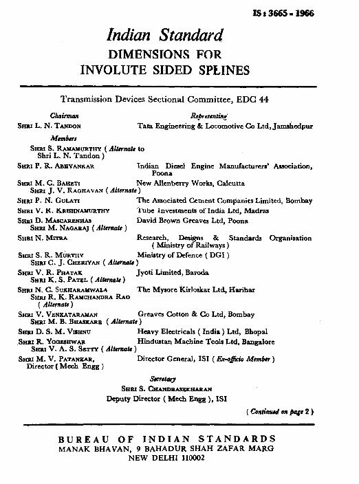
Transmission Devices Sectional Committee, EDC 44
Chairman Smu L. N. TANDON
Members
Representing’ Tata Engineering & Locomotive Co Ltd, Jamshedpur
Smu S. RAMAMIJRTHY ( AI&m& to Shri L. N. Tandon )
Snar P. R. A~EYANKAR Indian Diesel Engine Manufacturers’ Association, Poona
&rat M. C. B~tiart New Allenberry Works, Calcutta SHRI J. V. RAQHAVAN (Alternate)
SHRI P. N. Guun The Associated Cement Companies Limited, Bombay
SHRI V. R. KR~~HNWURTHY Tube Investments of India Ltd, Madras
Smu D. -m Srnu M. NAQARAJ ( Al&ma& )
David Brown Greavcs Ltd, Poona
SHRI N. Mrrru. Research, Designs & Standards Organlsation ( Ministry of Railways )
Sriar S. R. MURTHY Ministry of Defence ( DGI ) Srinr C. J. C~~RTYAN ( Almnate )
Smu V. R. PHATAK SHRI K. S. PATEL ( Altern& )
Jyoti Limited, Baroda
SHRI N. C. SIJXHARAI4wALA The Mysore Kirloskar Ltd, Harihar Smu R. K. RAM~HANDRA Rno
( Altcmare ) SHRI V. VENKATARAMAN Greaves Cotton & Co Ltd, Bombay
Ssim M. B. BIIASXARB ( Akaate )
Srmr D. S. M. Vrs~~u Heavy Elcctricals ( India) Ltd, Bhopal
.SHoI R. YOOSSHWAR Smu V. A. S. Sarry ( Alkrnalr )
Hindustan Machine Tools Ltd, Bangalore
SHRI M. V. PATANXAR, Director ( Mcch Engg )
Director General, IS1 ( E.r-q$i% Member )
titory Smu S. cgAllD~~~~4
Deputy Director ( Mcch Engg ), ISI
( coaliawd bn pags 2 )
BUREAU OF I.NDIAN STANDARDS hlANAK BHAVAN, 9 BAHADUR SHAH ZAFAR MARC3
NEW DELHI 110002

IS:3665-1966
( Confinuedfrom pugs 1 )
Splines and Serrations Subcommittee, EDC 44 : 4
Gmvencr
SHRI R. YOOEBKWAR
Members
Rspnscnting
Hmdustan Machine Tools Ltd, Bangalore
SHRI V. A. S. SRTrY ( &tmrcrh t0 Shri R. Yogeshwar )
SHRl M, C. BAHETI New Allenberry Works, Calcutta SRRI J. V. RAGHAVAN ( Alkmuk )
CHEEP ENOINRRR Heavy Electricals ( India ) Ltd, Bhopal SHIU K. RAMANATHAN ( Alkrnuk )
SHRI D. C. KOXLZ Hindustan Motors Ltd, Uttarpara
REPRESENTATIVE Automobile Products of India Ltd, Bombay
SHRI G. K. RUIKAR The Mysore Kirloskar Ltd, Harihar SI-IIU R. K. RAMCHANDRA RAO
( A&ma& )
SHRI K. SURYANNUYANA RAO Ashok Leyland Ltd, Madras
2
-_

IS:3665.1966
Indian Standard DIMENSIONS FOR
INVOLUTE SIDED SPLINES
0. FOREWORD
0.1 This Indian Standard was adopted by the Indian Standards Institu- tion on 2 July 1966, after the draft finalized by the Transmission Devices Sectional Committee had been approved by the Mechanical Engineering Division Council.
05 Splined shafts generally have the following three types of applications: _~ a) Coupling shafts when relatively heavy torques are to be transmitt-
ed without slippage,
b) Transmitting power to floating or permanently fixed gears, pulleys and other rotating members, and
c) Coupling parts that may require frequent removal for indexing or change of angular position.
0.3 External and internal splines are very extensively used in the automo- bile, machine tools and other industries. This standard has been prepared to rationalize the production and to facilitate interchangeability of exter- nal and internal splines.
0.4 This standard deals with involute sided splines of 30’ pressure angle for general engineeering ‘purposes. Separate standards on straight sided splines have already been prepared (see IS : 2327-1963* and IS : 2610-
I96W )* 05 The dimensions and fits given in the tables are based on the basic hole system. In this system the dimensions of the internal splines are the basis and variations in fit are obtained by varying the allowance on the external splines.
0.6 The tolerances for the spline tooth thickness and space width are given in Table 12. The instructions for the use of table is explained in Appen- dk A. The tolerance on major and minor diameters shall be according to the system of limits and fits specified in IS : 919-1963$.
0.7 Separate standards on gauging practice and the relevant manufacturing tools for splines are under preparation.
*Dimensions for straight sided splines for general engineering use.
tDimcnsions for straight sided splines for machine tools. ~Rccommendations for limits and fits for enginccriog ( rwised ).
3
IS : 3665 - 1966
0.8 As far as possible, the major diameters of external splines are given so as to end in numbers 0, 2, 5 and 8 which are standard diameters for ball bearings.
0.9 This standard is based on the following principles:
a) To cover the standard modules conforming to IS : 2535-1963*;
b) The same reference profile is used for all pitches and consequently, used for all profiles;
c) Centring by side fit or diameter fit; and
d) Use of profile displacement for the purpose of obtaining optimum utilization of materials.
0.10 This standard is based on draft standard DIN 5480-1964 Blatt 1 to 14 ’ Zahnwellen Verbindungen mit Evolventenflanken (Involute sided splines) ’ issued by the Deutscher, Nonnenausschuss.
0.11 For the purpose of deciding whether a particular requirement of this standard is complied with, the final value, observed or calculated, expressing the result of a test, shall be rounded off in accordance with IS : Z-1960?. The number of significant places retained in the rounded off vaIue should be the same as that of the specified value in this standard.
1. SCOPE
I.1 This standard covers the dimensions, for straight involute splina of
30” pressure angle, with three different types of fits, namely, major &a_
meter fit, minor diameter fit and side fit.
1.2 Involute splines of modules (l), 1.25, (l-5), 2, (Z-5), 3, (4), 5, (6), 8 and (10) are covered in this standard. The values given within brackets are non-preferred.
2. DEFINITIONS
2.0 For the purpose of this standard, the following definitions shall apply.
2.1 A&ual Space Width - The circular width on the pitch circle of any single space ( see Fig. 1 ).
2.2 AdaI Tooth Thickness - The circular thickness on the pitch circle of any single tooth ( 58~ Fig. 2 ).
*&sic rack, modules and diametral pitches of cylindrical gears for general e&re&ng_ ( Since revised ) .
tR&s for rounding off numerical values ( revised).
4

r-PITCH ERROR
PROFILE ERROR
a) Each Space is Basic Width b) Perfect External Spline with Basic Tooth Thickness Interferes at X
&FFECTlVE SPACE WIDTH EQUALS TOOTH THlCKNESS OF PERFECT EXTERNAL SPLINE
c) The perfect External Spline fits in any POSitiOn, if all Spaces of the Internal Spline are Widened ly the Amount of‘lnterference
FIG, 1 EFFF,CT OF INTERNAL SPL~NB ERRORS
5

ACTUAL TOOTH THICKNESS
TIVE TOOTH THICKNESS EQUALS SPACE WDTH OF
PERFECT INTERNAL SPLINE
FIG. 2 EFFECT OF EXTERNAL SPLINE ERRORS
2.3 Base Circle Diameter - The diameter of the circle from which involute spline tooh profiles are constructed.
2.4 Effective Clearance - The difference between the effective space width of the internal spline and the effective tooth thickness of the mating external spline ( see Fig. 3 ).
2.5 Effective Error - The accumulated effect of the spline errors on the fit with the mating parts.
2.6 Effective Space Width of an Internal Spline - The circular tooth thickness on the pitch circle of an imaginary perfect external spline which would fit the internal spline without looseness or interference ( see Fig. 1).
2.7 Effective Tooth Thickness of an External Spline - The circular space width on the pitch circle of an imaginary perfect internal spline which would fit the external spline without looseness or interference ( see Fig. 2 ).
2.8 Error Allowance - The permissible effective error.
2.9 Involute Spline - The spline having teeth with involute profiles.
2.10 Machining Tolerance - The permissible variation in actual space width or actual tooth thickness ( see Fig. 3 ).
2.11 Main Pressure Angle ( a0 : - The pressure angle at the pitch point.
2.12 Major Diameter - The diameter of the outermost surface of the spline. It is the root diameter of the internal spline or the tip diameter of the external spline.

is:36651 1966
BASIC SIZE
I EFFECTIVE DIMENSIONS I ACTUAL DIMENSIONS
-
FIG. 3 FIT DIAGRAM OF SPLINB ASSEMBLY 120 x 114 x 38x 8HE/8eb IS : 3665
2.13 Minor Diameter-- The diameter of the innermost surface of the spline. It is the tip diameter of the internal spline or the root diameter of the external spline.
2.14 Module (m) - The ratio of the pitch circle diameter to the number of spline teeth.
2.15 Nominal Clearance - The difference between the actual space width of an internal spline and the actual tooth thickness of the mating external spline. This does not define the fit between the mating members, because of the effect of errors.
2.16 Pitch Circle Diameter - The diameter of an imaginary reference circle ( pitch circle ) from which all transverse dimensions are derived.
2.17 Pitch Point - The point of intersection of the spline tooth profile with the pitch circle.
2.18 Pressure Angle -The acute angle between a line tangent to a pro file of the spline and a radial line through the point of tangency. Unless otherwise specified the pressure angle shall mean the main. pressure angle,
7

1st 3665-1966
2.19 Profile Displacement ( xm ) - The displacement of the basic rack either away or towards the reference cylinder and is denoted by xm. The former is taken as positive and latter as negative profile displacement.
2.20 Spline - A machine element consisting of integral keys ( spline teeth ) or keyways ( spaces ) equally spaced around a circle or a portion thereof.
2.21 Total Tolerance - The sum of the machining tolerance and the error allowance ( see Fig. 3 ).
3. TYPES
3.1 External Spline - An involute spline whose tip surface is external to the root surface.
3.2 Internal Spline - An involute spline whose tip surface is internal to the root surface.
4. EFFECTIVE AND ACTUAL DIMENSIONS
4.1 The effective dimensions and actual dimensions together determine the fit of a spline assembly.
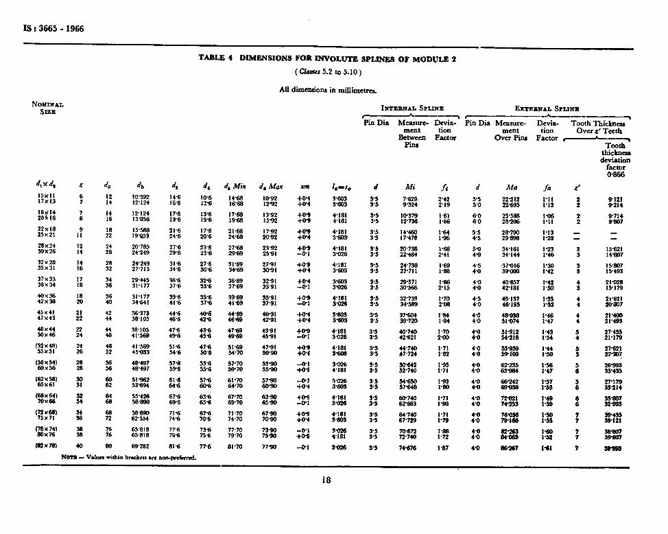
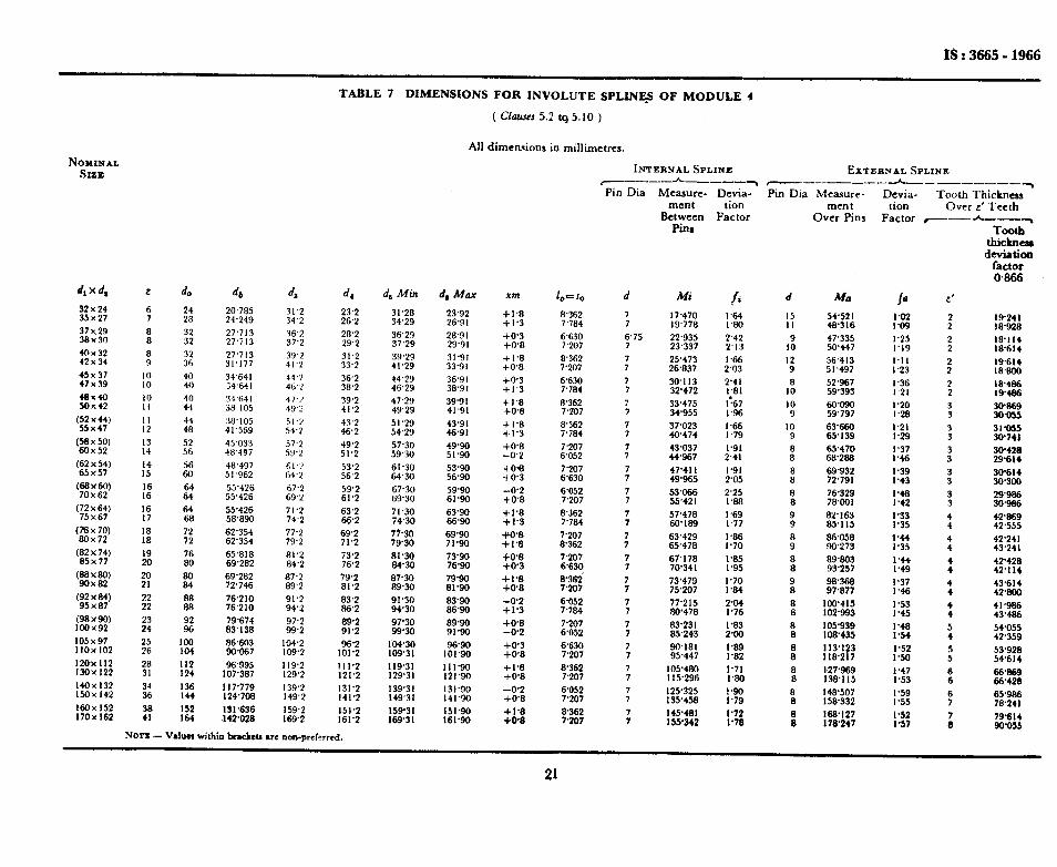
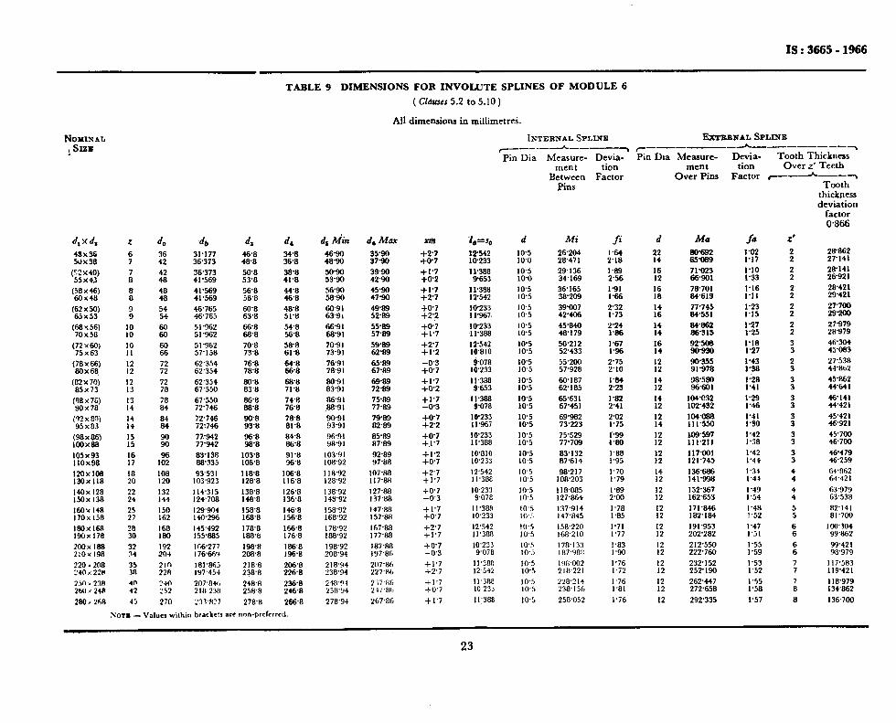
5. DIMENSIONS, TOLERANCES AND FITS
5.1 Reference profile for the different pitches shall be as given in Fig. 4.
5.2 Major Diameter of Internal Spline ( d, ) -This is the reference diameter of the profile, and the value shall be according to Tables 1 to 11.
5.3 Profile Displacement ( rm ) - The value of the profile displacement shall be calculated from the following formula ( see Tables 1 to 11 ):
xm= l/2 (d,-m.t-l-1 m)
The value shall be from - 0.05 m to + 0.45 m.
5.4 Number of Teeth ( z) -The number of teeth shall be calculated from the following formula ( see Tables 1 to 11 ):
z =k(d,--2xm- I.1 m)
where dI is the major diameter of the internal spline.
5.5 Minor Diameter of the Internal Spline ( d, ) - The value of the minor diameter of the internal spline shall be calculated from the follow_ ing formula ( see Tables 1 to 11 ):
d, = m.z + 2 xm- 0*9m= da - 2 m
8

Fro. 4 REWRBNCE PROFILB
5.6 Major Diameter of the External Spline ( da ) - The value of the major diameter of the external spline shall be calculated from the following formula ( see Tables 1 to 11 ):
iis = m.2 + 2xm + 0.9 m = dl - O-2 m
5.7 Minor Diameter of the External Splines ( d4 ) - Minor diameter of the external splines shall be calculated from the following formula (see Tables 1 to 11 ):
Id,= m.z + 2 xm - 1.1 m = dl - 2.2 m
5.8 Space Width and Tooth Thickness ( lo and S, ) - The value of the tooth thickness and space width shall be calculated from the following formula ( see Tables 1 to 11 ):
1, and s.=mf $- 2.xm. tanu,
5.9 The measuring pin diameter, the measurement over pins for the exter- nal splines and the measurement between pins for the internal splines shall be as given in Tables 1 to 11 ( scc Fig. 5 ).
5.9.1 Tolerance on Measurement 0~ Pins - The tolerance values on eEec_ tive and actual measurement over. pins shall be obtained by multiplying the tolerance values on the effectrve and actual tooth thickness by the deviation factor f. ( Tables 1 to 11 ).
5.9.2 Tolerance on Measurement Between Pins - The tolerance on effective and actual measurement between pins shall be obtained by multiplying the tolerance values on the effective and actual space width by the deviation factorfd ( Tables 1 to 11 ).
9

I Mi (FOR EVEN
Mi NUMBER (FOR 000 OF TEETH) NUMBER
OF ?EElH)
t I
Internal Spllnr External Spline
FIG. 5 MEASUREMENT BETWEEN PINS AND MEASUREMENT OVER PINS
Is:3665-1966
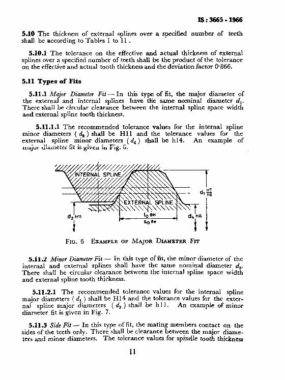
5.10 The thickness of external splines over a specified number of teeth shall be according to Tables 1 to 11 .
5.10.1 The tolerance on the effective and actual thickness of external splines over a specified number of teeth shall be the product of the tolerance on the effective and actual tooth thickness and the deviation factor 0.866.
5.11 Types of Fits
5.11.1 Major Diameter Fit - In this type of fit, the major diameter of the external and internal splines have the same nominal diameter dl. There shall be circular clearance between the internal spline space width and external spline tooth thickness.
5.11.1.1 The recommended tolerance values for the internal spline minor diameters ( ds ) shall be Hl 1 and the tolerance values for the external spline minor diameters ( d4 ) shall be h14. major diameter fit is given in Fig. 6.
An example of
FIG. 6 EXAMPLE OF MAJOR DIAMETER FIT
5.11.2 Minor Diameter Fit - In this type of fit, the minor diameter of the internal and external splines shall have the same nominal diameter d,. There shall be circular clearance between the internal spline space width and external spline tooth thickness.
5.11.2.1 The recommended tolerance values for the internal spline major diameters ( dl ) shall be H14 and the tolerance values for the exter- nal spline major diameters ( d3 ) shall be hl 1. An example of minor diameter fit is given in Fig. 7.
5.11.3 Side Fit - In this type of fit, the mating members contact on the sides of the teeth only. There shall be clearance between the major diame- ters and minor diameters. The tolerance values for spindle tooth thickness
11

Is:366511966
and space width for the spline qualities 7,8, 9 and 10 shall be as given in Table 12.
NOTE - Instructions for the use of Table 12 is given in Appendix A.
FIG. 7 EXAHPLE OF MINOR DIAMETER FIT
5.11.3.1 The recommended tolerance values for the major diameters of internal spline ( dl ) shall be H14, the minor diameters of internal spline ( d, ) shall be HI I, the major diameters of external spline ( d, ) shall be hll and the minor diameters of external spline ( d, ) shall be h14. An example of side fit is shown in Fig. 8.
FIG. 8 EXAMPLE OF SIDE Fm
5.11.4 A typical example of effective tooth thickness, effective space width, actual tooth thickness and the actual space width for three types of fits, namely, press fit, lrcating fit and sliding fit, is shown in Table 13,
12

6. DESIGNATION
6.1 Side Fit
6.1.1 An involute
IS:3665-1966
sided spline of a spline assembly of side fit shall be designated by the type of spline, nominal size ( dl x ds ), number of- teeth of the spline, the tolerance on the effective and actual dimensions; of space width for internal splines, and of tooth thickness for external spline, followed by the number of this standard.
Example:
An external involute spline of nominal size 120 x 114 mm with 38 spline teeth, and with the tolerance symbols 8e and 8b on the effective and actual tooth thickness shall be designated as:
External Involute Spline 120 x 114 x 38 X 8eb IS : 3665
6.1.2 A side fitted spline assembly shall be designated by the nominal size, number of teeth d the spline, the effective and actual fit of the spline teeth and the number of this standard.
A spline assembly of nominal size 120 x 114, with 38 spline teeth and the fit 8 HE/8eb on the effective and actual spline teeth shall be designated as:
Spline Assembly 120 x 114 x 38 x 8 HE/8eb IS : 3665
6.2 meter Fit - Spline assembly of major and minor diameter fit shall be designated as in 6.1.2 along with the value of fit on their respective diameters.
Examples:
4
b)
A spline assembly of major diameter fit of H7/h6 of external involute spline, 120 x 114 x 38 X 8eb and internal involute spline 120 x 114 x 38 x 8 HE shall be designated as:
Spline Assembly 120 H7/h6 x 114 X 38 x 8 HE/8eb IS : 3665
A spline assembly of minor diameter fit of H7/h6 of external involute spline, 120 x 114 x 38 x 8eb and internal involute spline 120 x 114 x 38 x 8 HE shall be designated as:
Spline Assembly 120 x 114 H7/h6 X 38 x 8 HE/8eb IS : 3665
13

As in the Original Standard, this Page is Intentionally Left Blank


IS : 3665 - 1966
TABLE 13 EXAMPLES OF EFFECTIVE AND ACTUAL DIMENSIONS, TOLERANCES FOR DIFFERENT FITS
(Claws 5.11.4)
SPLINE TYPE
TOLERANCE ZONE ~--___c,
Effective Actual
FIT
Internal @line E
hl
;J Press fits
Extemal Spline jh e Locating fit
Sliding fits
APPENDIX A ( Clause 0.6 )
INSTRUCTIONS FOR USING TABLE 12
A-l. GENERAL
A-l.1 This appendix covers the method for reading the tolerance values on @ace width and tooth thickness of four qualities of involute splines, represented by the quality lines qlq2, q3qa, etc. The modules up to 10 have been divided into three ranges, represented by module lines mp,, %m4 and me. The pitch circle diameters up to 800 mm have been divided into 6 ranges, represented by the lines pIp2, p3p4, etc.
A-2. PROCEDURE FOR USING THE TABLE
A-2.1 The procedure has been explained with a particular example of external spline of module 2, pitch circle diameter 120 mm, quality 8 and tolerance tn.
A-2.2 The module line for the spline of module 2 is m3m4. circle diameter line for 120 mm is P&.
The pitch The module line m3m4 and pitch
circle diameter line P,Ps meet at a point ‘a’, and from the point ‘a’, a spline line leads down to the quality line q3qa, corresponding to quality 8, meeting at point ‘b’. The tolerance value is read under the tolerance symbol m against the point ‘6’. The tolerance value for the tooth thickness of the spline is + 60 and + 20 micrometres.
27

BUREAU DF INDIAN STANDARDS
Manak Bhavan, 9 Bahadur Shah Zatar Marg, NEW DELHI 110002 Telephones: 323 0131,323 3375,323 9402 Fax : 91 11 3234062,91 11 3239399, 91 11 3239382
Central Laboratory:
plot No. 20/9, Sita IV, Sahihahad lndustriat Area, Sahihahad 201010
RegIonal OMces:
Tebgrams : Manaksanstha (Common to all Officas)
TObphollO
0-77 00 32
Central : Manak Bhavan, 9 Bahadur Shah Zatar Mug, NEW DELHI 110002 323 76 17
*Eastam : l/14 CIT schema VII M, V.I.P. Road, Maniktola, CALCUTTA 700054 33706 62
Northam : SC0 335-336, Sector 34-A, CHANDIGARH 160022 60 30 43
Southern : C.I.T. Campus, IV Cross Road, CHENNAI 600113 235 23 15
tWruz&zaya, E9, Bahind Marol Tabphona Exohange, Andhsri (East), 832 92 95
Branch Offlcr::
Pushpak’, Nurmohamad Shaikh Marg, Khanpur, AHMEDABAD 380001
$Peanyaindustrial Area, 1st Stage, Bangcrlors-Tumkur Road,
5501348
8394955 - BANGALORE 560058
Gangotd Compbx, 5th Floor, Bhadhhada R&d, T.T. Nagar. BHOPAL 462003_
Plot No. 62-63. Unit VI, Ganga Nagar, BHUBANESHWAR 751001
Kabikathir Buildings, 670 Avinashi Road, COIMBATORE 641037
Plot No. 43, S&or 16 A. Mathun Road, FAAIDABAD 121001
Savitri Complex. 116 G.T. Road, GHAZtABAD 201001 I 5315 Ward No.29, R.G. Barua Road, 5th Byqana, GUWAHATI 781003
5-E-56C, L.N. Gupta Marg,.Nampally Station Road, HYDERABAD 506001
E-52, Chitaranjan Marg, C-Scheme, JAIWR 302001
117/418 B, Sarvodaya Na9ar, KANPUR 206005
Seth Bhawan, 2nd Floor, Bahind Laak Ctnama, Naval Kbhore Road,
55 40 21
40 36 27
21 01 41
8-28 86 01
0-71 1996
541137
201083
37 29 25
21 60 76
23 09 23 LUCKNOW 226001
NIT Building. Second Floor, Gokulpat Market;NAGPUR 440010 52 51 71
Patiiputra Industrial Estate, PATNA 800013 26 23 05
Institution of Engineers (India) Building 1332 Shiii Nagar, PUNE 411005 32 36 35
T.C. No. 14/1421, Univarsity P. 0. Pabyam, THIRUVANANMAPVRAM 695034 621 17
*Sales Cttiie is at 5 Chowringhea Approach, P.O. Prino~p Street, CALCUTTA 700072
271085
tSabs Ctfroe is at Novelty Chambers, Grant Road, MUMBAI 400007
$Sabs CHice is at ‘F’ Block. Unity Building; Narashrmaraja Square, BANGALORE 560002
309 65 26
222 39 71
Primed al Slmco Printing Press, Delhi. India