IS 3455 (1971): Gauging practice for plain work pieces · UDC 621’753’2 : 531’718’1 Fifth...
20
Disclosure to Promote the Right To Information Whereas the Parliament of India has set out to provide a practical regime of right to information for citizens to secure access to information under the control of public authorities, in order to promote transparency and accountability in the working of every public authority, and whereas the attached publication of the Bureau of Indian Standards is of particular interest to the public, particularly disadvantaged communities and those engaged in the pursuit of education and knowledge, the attached public safety standard is made available to promote the timely dissemination of this information in an accurate manner to the public. इंटरनेट मानक “!ान $ एक न’ भारत का +नम-ण” Satyanarayan Gangaram Pitroda “Invent a New India Using Knowledge” “प0रा1 को छोड न’ 5 तरफ” Jawaharlal Nehru “Step Out From the Old to the New” “जान1 का अ+धकार, जी1 का अ+धकार” Mazdoor Kisan Shakti Sangathan “The Right to Information, The Right to Live” “!ान एक ऐसा खजाना > जो कभी च0राया नहB जा सकता ह ै” Bhartṛhari—Nītiśatakam “Knowledge is such a treasure which cannot be stolen” IS 3455 (1971): Gauging practice for plain work pieces [PGD 25: Engineering Metrology]
Transcript of IS 3455 (1971): Gauging practice for plain work pieces · UDC 621’753’2 : 531’718’1 Fifth...

Disclosure to Promote the Right To Information
Whereas the Parliament of India has set out to provide a practical regime of right to information for citizens to secure access to information under the control of public authorities, in order to promote transparency and accountability in the working of every public authority, and whereas the attached publication of the Bureau of Indian Standards is of particular interest to the public, particularly disadvantaged communities and those engaged in the pursuit of education and knowledge, the attached public safety standard is made available to promote the timely dissemination of this information in an accurate manner to the public.
इंटरनेट मानक
“!ान $ एक न' भारत का +नम-ण”Satyanarayan Gangaram Pitroda
“Invent a New India Using Knowledge”
“प0रा1 को छोड न' 5 तरफ”Jawaharlal Nehru
“Step Out From the Old to the New”
“जान1 का अ+धकार, जी1 का अ+धकार”Mazdoor Kisan Shakti Sangathan
“The Right to Information, The Right to Live”
“!ान एक ऐसा खजाना > जो कभी च0राया नहB जा सकता है”Bhartṛhari—Nītiśatakam
“Knowledge is such a treasure which cannot be stolen”
“Invent a New India Using Knowledge”
है”ह”ह
IS 3455 (1971): Gauging practice for plain work pieces [PGD25: Engineering Metrology]


UDC 621’753’2 : 531’718’1 Fifth Rqrint NOVEMBER 1996 ( Incorporating Amendments No. 1 to 4 1 IS : 3455 - 1971
.
4
Indian Standard
GAUGING PRACTICE FOR PLAIN WORKPIECES ( Firsf Revision )
1. Scope-Lays down the gauging practice for inspection of plain workpieces with dimensions fess than 500 mm. This standard also gives the manufacturing tolerances and the permissible wear limit of the gauges.
2. Inspection Gauging of Plain Workpieces
2.1 Unless specified to the contrary, inspection by limit gauges is recognized as the acceptable method for dimensional conformity to the specification of plain workpieces. To avoid any dispute requiring checking of the conformity of the gauges of the manufacturer, the following procedure is recommended in the use of gauges of the manufacturer and of the purchaser.
2.2 lnspecfion by fhe Manufactorer - Generally the inspection department that checks the workpieces made in the workshop may use the same types of gauges as those used in the workshop. In order to avoid differences between the results obtained by the workshop and inspection department it is recom- mended that the workshop uses new or only slightly worn gauges whilst the inspection department uses gauges having sizes nearer the permissible wear limit.
2.3 lnspecfion by the Purchaser- There are three possible procedures for inspection on behalf of the purchaser by an inspector who does not belong to the manufacturing plant concerned:
a) the inspector may gauge the workpieces with the manufacturer’s own gauges, providing he first checks the accuracy of these gauges;’
b) the inspector may use his own gauges, made in accordance with this standard, for inspecting workpieces. It is recommended that these gauges should have sizes near the wear limit in order to avoid differences between the results obtained by the manufacturer and the inspector;
c) the inspector may use his own inspection gauges for checking the workpieces. The diS- position of the tolerance zones for these gauges should besuch as to ensure that the inspector does not reject workpieces the sizes of which are within the Specified limits.
3. Reference Temperature
3.1 The standard reference temperature for all industrial length measurements shall be 20°C. This is also the temperature at which dimensions specified for workpieces and the inspection instruments are defined and at which the inspection should normally be carried out.
3.2 If the workpieces and the gauges have the same coefficient of linear expansion ( for example, steel workpieces and steel gauges ), the checking temperature may deviate from 20°C without detriment to the result, provided that the temperatures of both gauges and workpieces are the same.
3.3 If the workpieces and gauges have different coefficients of linear expansion (for example, steel workpieces and carbide gauges or brass workpieces and gauges of steel or carbide ), the temperatures of both &hould be close to 20°C at the time of gauging.
4. Limits of Size for Gauging (Taylor Principle )
4.1 In order to ensure, as far as is practicable, that the functional requirements of the limits of sizes as given in IS : 919-I 963 ’ Recommendations for limits and fits for engineering ( revised ) ’ are attained, the limits of size should be interpreted in the following way within the basic dimensions:
a) For holes, the diameter of the largest perfect imaginary cylinder which can be inscribed within the hole so that it just contacts the highest points of the surface, should not be a diameter smaller than the GO limit of size. In addition, the maximum diameter at any position in the
hole shall not exceed the NO GO limit of size.
b) For Shafts, the diameter of the smallest perfect imaginary cylinder which can be circumscribed about the shaft so that it just contacts the highest points of the surface, should not be a diameter larger than the GO limit of size. In addition, the minimum diameter at any position on the Shaft shall not be less than the NO GO limit of size.
Adopted 20 September 1971 I
@ April 1993, BIS I_
BUREAU OF I.NDIAN STANDARDS
MANAK BHAVAN, 9 BAHADUR SHAH WAR MAFtG
NEW DEU-II 110002 .:., ,4

<
IS:3455- 1971
4.1.1 The above interpretation means that if the size of the hole or shaft is everyzdhere at its GO limit then the hole of shaft shall be perfectly round and straight.
4.2 Subject to the above requirements, departures from true roundness and straightness may reach the full value of the diametral tolerance specified. tation are illustrated in Fig. 1 and 2.
Typical extreme errors of form permitted by this interpre- Such extreme errors are unlikely to arise in practice.
Note-The above interpretation of the size limits results from the so-called Taylor principle, called after the name of the late W. Taylor who first laid it down in 1905. It is based on the use of a correct system of limit gauges to inspect shafts and holes. According t-o this principle a hole should completely assemble with a GO cylindrical plug gauge,made to the specified GO limit of the hole, having a length at least equal to the length of engagement of the hole and shaft. In addition, the hole is measured or gauged to check that its maximum diameter is not larger than the NO GO limit.
4.2.1 The shaft should assemble completely with a ring gauge made to the specified GO limit of the shaft and of a length at least equal to that of the length of engagement of the shaft and hole. Finally the shaft is measured or gauged to check that its minimum diameter is not smaller than the NO GO limit.
4.2.2 In special cases the maximum errors of form permitted by the above interpretation may be too large to allow satisfactory functioning of the assembled parts; in such cases separate tolerances should be given for the form, for example, separate tolerances on circularity or straightness.
INSCRIBED CYLINDER
FIG. 1 EXTREME ERRORS OF FORM OF HOLE ALLOWED BY THE RECOMMENDED
INTERPRETATION OF THE LIMITS OF SIZE
5. Application of the Taylor Principle - Except for allowable deviations (see 6 ) strict application of the Taylor principle leads to using:
a) a plug gauge or a ring gauge having exactly the GO limit diameter and a length equal to the workpiece length ( or the engagement length of the fit to be made) for checking the GO limit of the workpiece; and
b) a gauge contacting the workpiece surface only in two diametrically opposite points and having exactly the NO GO limit diameter for checking the NO GO limit.
5.1 The GO gauge should perfectly assemble with the workpiece to be inspected and the NO GO gauge should not be able to pass over or in the workpiece in any consecutive position in the various diametrical directions on the workpiece length. ( In order that the GO and NO GQ limits should not be trespassed, manufacturing and wear tolerances should be taken within these limits. )
6. Allowable Deviation from the Taylor Principle - As the application of the Taylor principle is not always strictly compulsory or comes up against difficulties in conveniently using gauges, certain deviations may be allowed ( see 7.9 ).
2

IS: 3455- 1971
6.1 At the
a)
b)
c)
-GO LIMIT G-1 GO LIMIT
NOT GO LIMIT I-- NOT GO LIMITS CIRCUMSCRIBED
k-GO LIMIT -----i L GO LIMIT 2
FIG. 2 EXTREME ERRORS QF FORM OF SHAFT ALLOWED BY THE RECOMMENDED
INTERPRETATION OF TH,E LIMITS OF SIZE
GO limit a full form gauge is not always necessary or used. For instance:
The length of a GO cylindrical plug or ring gauge may be less than the length of engagement of the mating workpieces if it is known or assumed that with the manufacturing process used the error of straightness of the hole or shaft is so small that it does not affect the character of fit of the assembled workpieces. This deviation from the ideal facilitates the use of standard gauge blanks.
For gauging a large hole a, GO cylindrical plug gauge may be too heavy for convenient use, and it is permissible to use a segmental cylindrical bar or spherical gauge if it is known or assumed that with the manufacturing process used the error of roundness of the hole is so small that it does not affect the character of fit of the assembled workpieces.
A GO cylindrical ring gauge is often inconvenient for gauging shafts and may be replaced by a gap gauge if it is known or assumed that with the manufacturing process used the errors of roundness ( especially lobing ) and straightness of the shaft are so small that they do not affect the character of fit of the assembled workpieces. which have a small diameter, should be checked separately.
The straightness of long shafts,
6.2 At the NO GO limit a two-point checking device is not always necessary or used. For instance:
a)
b)
Point contacts are subject to rapid wear, and in most casis may be replaced where appro- priate by small plane, cylindrical or spherical surfaces.
For gauging very small holes a two-point checking device is difficult to design and manu- facture. NO GO plug gauges of full cylindrical form have to be used but the user must be aware that there is a possibility of accepting workpieces having diameters outside the NO GO Limit.
c) Non-rigid workpieces may be deformed to an Oval by a two-point mechanical contact device operating under a finite contact force. If it is not possible to reduce the contact force to almost zero, for example, by using a direct jet pneumatic device, then it is necessary to.use NO GO ring or plug gauges of full cylindrical form.
6.3 Some thin-wa!led_workpieces Fay be out of round ( $ue t? internal stresses or heat treatment ). ln these cases the N3 GO limit has the meaning that the ClrCUmterenCe of the cylinder corresponding t6 that limit shall not be transgressed. Therefore NO GO gauges of full cylindrical form have to be applied with a force that just suffices to convert the elastic deformation into circularity but does not expand or compress the wall of the workpiece.
3

IS:3455-1971
6.4 Lastly, it is not possible to make the gauges exactly to the appropriate workpiece limit; they require to be made to specified tolerances.
7. Limit Gauges
7.0 Limit gauges are used to inspect the workpieces. For gauging internal diameters, they are of the following types:
a) Full form cylindrical plug gauge,
b) Full form spherical plug or disk gauge,
cl Segmental cylindrical bar gauge,
d) Segmental spherical plug gauge,
e) Segmental cylindrical bar gauge with reduced measuring faces, and
f) Rod gauge with spherical ends.
7.0.1 For gauging external diameters, they are of the following types:
a) Full form cylindrical ring gauge, and
b) Gap gauge.
7.0.2 To inspect or adjust limit gauges, the following gauges may be’used:
a) Referencegauges are either reference disks intended for setting gap gauges, or cyfindri- cal ring or plug gauges used for calibrating gauges or indicating measuring instruments.
b) Block gauges are standards of length having parallel plane end surfaces which are used for calibrating gauges of indicating measuring instruments.
7.1 A fu// form cylindrical plug gauge ( Fig. 3A ) has a gauging surface in the form of an external cylinder. The method of attaching the gauge to the handle should not affect the size and form of the gauge by producing an undesirable stress.
7.1.1 A small circumferential groove near the leading end of the gauge and a slight reduction in dia_ meter of the remaining short cylindrical surface at the end are recommended to serve as a pilot to facilitate the insertion of the gauge into the workpiece hole.
7.2 A full form spherical plug or disk gauge ( Fig. 3B ) has a gauging surface in the form of a sphere from which two equal segments are cut off by planes normal to the axis of the handle.
7.3 A segmental cylindrical bar gauge ( Fig. 3C 1 has a gauging surface in the form of an external cylinder from which two axial segments are either received [ Fig. 3C (i) ] or removed [Fig. 3C (ii) 1. This gauge may have reduced measuring faces ( Fig. 3E ).
7.4 A segmentalspherical plug gauge ( Fig. 3D ) is similar to Fig. 3B but has two equal segments cutoff by planes parallel to the axis of the handle in addition to the segments cut off by planes normal to the axis of the handle.
7.5 A segmental cylindrical bar gauge with reduced measuring faces ( Fig. 3E ) is similar to Fig. 3~ but has reduced measuring faces in a plane parallel to the axis of the handle.
7.6 A r& gauge with spherical ends ( Fig. 3F ) has spherical end surfaces which form part of one single sphere.
7.7 A full form cylindrical ring gauge ( Fig. 4A) has a gauging surface in the form of an internal cylinder. The wall of the ring pauge shall be thick enough to avoid deformation under normal condi- tions of use.
4

IS: 3455 - 1971
7.8 A gap gauge ( Fig. 48) has for its working size flat and parallel gauging surfaces, or alternatively and preferably has one flat and one cylindrical surface, or two cylindrical surfaces, the axes of these cylindrical surfaces being parallel to the axis of the shaft being checked. The GO and NO GO gaps may lie on the same side of the gap gauge. Tha gap gauge may be fixed or adjustable.
A D Fui_l FORM CYLINDRICAL PLUG GAUGE B o- FULL FORM SPHERICAL PLUG OR DISC GAUGE
a- SEGMENTAL CYLINDRICAL BAR GAIJGE
a- ~EG~ENl.&SPHERICAL E o- SEGMENTAL CVLINORICAL BAR GAUGE WITH REWCEO MEASURIN@FACES
F a_0 ~00 GAUGE WITH SPHERICAL ENDS
FIG. 3 RECOMMENDED TYPES OF GAUGES FOR HOLES AND THEIR
CORRESPONDING SYMBOLS FOR FIG. 5
A@ FULL FORM CYLINDRICAL Bk9 GAP GAUGE
RING GAUGE
FIG. 4 RECOMMENDED TYPES OF GAUGES FOR S’HAkTS AND THEIR
CORRESPONDING SYMBOLS FOR FIG. 6

IORKPIECE GAUGES p;yFE;RfCE ,, DIAMETER IN mm
I I I
1 t--=D
- 120 315 500 I
TAYLOR +m- q - -+- ++-
GO
2 -o-o-
1
r +----x3
TAYLOR ____ct)__ o- -+- (j+)-
[r GO a4
2 0 l-----c------i
P
:.
s NOT GO I
IS : 3455 - 1971
7.9 The various types of gauges explained above are illustrated in Fig. 3 and 4. The recommended types of gauges for the different ranges of nominal size of the workpieces are shown in Fig. 5 and 6. The keys to the symbols used in Fig. 5 and 6 are given in Fig. 3 and 4.
FIG. 5 TYPES OF GAUGES USED TO CHECK HOLES, IN ORDER OF PREFERENCE
ORDER OF DIAMETER IN mm WORKPIECE GAUGES PREFERENCE o
I- 0 TAYLOR s-1
FIG. 6 TYPES OF GAUGES USED TO CHECK SHAFTS, IN ORDER OF PREFERENCE
8. Inspection of Gauge Sizes
8.1 Reference Gauges- The gauge diameter should be measured between a plane and a spheri- cally-ended anvil having a minimum radius of IO mm. The value obtained should be corrected for deformation of the surfaces in contact caused by the measuring force, that is, the diameter of the gauge is the diameter when the measurjng force is zero. The diameter should be measured in at least four positions selected to reveal form errors.
8.1.1 All the measured diameters of the gauge should be on or between the specified limits of size, and the range, that is, the difference between the maximum and minimum values, should not exceed the form tolerance of the gauge ( see 10.2.3 ), If the presence of lobing is suspected then it may be checked by a three-point measurement or by a roundness measurement.
6

IS : 34559 1971
8.2 Spherical Plug, Disk and Red Gauges -The diameter of the spherical part of the gauge should be measured between two parallel planes; these planes need only have a small area, for example, the diameter of the plane-ended surface of the anvil of a measuring instrument may only be 5 mm.
8.2.1 The value obtained should be corrected for deformation of the surfaces in contact caused by the measuring force, that is, diameter of the gauge is the diameter when the measuring force is zero.,
8.2.2 The diameter should be measured in. at least four positions, selected to reveal form errors. All ihe measured diameters of the gauge should be on or between the specified limits of size, and the range, that is, the difference between the maximum and minimum values, should not exceed the form tolerance of the gauge (see 10.2.3). If the presence of lobing is suspected then it may be checked by a three- point measurement or by a roundness measurement.
8.3 Cylindrical Ring Gauges- The -diameter is measured by means of t,wo spherically-ended anvils . positioned in a plane normal to the axis of the ring gauge. When moving the measuring instrument in
this plane the greatest distance apart of’the two anvils determines the diameter. The value obtained should be corrected for deformation of the surfaces in contact caused by the measuring force, that is, the diameter of the gauge is the diameter when the measuring force is zero.
8.3.1 The diameter should be measured in at least four positions, selected to reveal form errors. All the measured diameters of the gauge should be on or between the specified limits of size, and the range, that is, the difference between the maximum and minimum values, should not exceed the form tolerance of the gauge (see 10.2.3 ‘). If the presence of lobing is suspected then it may be checked by a three-point measurement or by a roundness measurement.
8.4 Gap Gauges
8.4.1 The actual size of a gap is defined as the perpendicular distance between the gauging surfaces, when no force is exerted on the gauge.
8.4.2 The working size of a gap gauge is defined as the diameter of a reference disk over which the gap gauge just passes in a vertical direction under the working load marked on it, ar, if this is not indicated, under its own weight. Beforehand, the disk should be greased with a thin film of petroleum jelly and then carefully wiped but not rubbed. cleaned. The gap gauge should slide over
The gauging surfaces of the gap gauge should be the disk after having been brought carefully to rest in
contact with the disk and then released: inertia forces are so avoided.
8.4.3 For heavier gap gauges it is recommended that the working load should be less than the weight of the gauge, so that the working size may be determined more accurately. The positions of the places where the forces counterbalancing part of the weight of the gauge are to be applied ( see Fig. 7 ) should be marked on gauges of nominal sizes above 100 mm.
FIG. 7 LOCATION OF POINTS WHERE FORCES COUNTERBALANCING PART OF WEIGHT OF GAUGE SHOULD BE APPLIED
8.4.4 The working size of a gap gauge is not defined with a zero measuring force, as for the other definitions, because the size of a reference disk is defined with a zero measuring force and the gap gauge may be regarded as a comparator which is intended to transfer ( on the particular limit ) the size of the reference disk to the workpiece.
8.4.5 In practice a reference disk may be used directly to accept a gap gauge in the case where the disk and the gap gauge are supplied together and the gap gauge has been adjusted to the disk. 10 other cases the following two alternative procedures are recommended:
a) The successive loads under which the gap gauge will pass over twq reference disks of different diameter are determined under the conditions specified in the definition of the working size. The difference in these two loads is taken as a basis for calculating the working size of the gap gauge at its working load.
7

IS:3455- 1971
b) A reference disk is taken with a diameter smaller * than the smallest permissible size of the
gap gauge. Gauge blocks are wrung successively on the gauging surfaces of the gap gauge, if possible equally distributed so that in one case the sum of the diameter of the reference disk and the gauge blocks is equal to the lowest permissible working size and in the other case to the highest permissible working size of the gap gauget.
In the first case the gap gauge should pass over the reference disk, and in the second case it should not pass over the reference disk, under the conditions specified in the definition of the working size.
Doubtful cases are decided according to method ( b) above.
8.4.8’When the gap gauge is used in a horizontal position, with the axis of the workpiece vertical, its working size is defined as the largest size of a reference disk or gauge block combination over which it can just be moved by band without excessive force.
8.4.7 The difference between the working size and the actual size of a gap gauge is equal to the amount by which the gauge is deformed by the force applied when determining the working size. The design of the gap gauge should be as rigid as possible in relation to the weight of the gauge so as to keep this difference in size to a minimum.
9. Method of Use of Gauges -The following recommendations relate to the general use of the gauges in the workshop as well as in inspection.
9.1 Gauges for Holes
GO Gauge -A GO gauge should assemble completely with the hole when applied by hand without using excessive force, and the total length of the hole should be checked. When gauging non-rigid workpieces, such as thin-walled parts, the application of too great a force will enlarge the diameter of the hole. A GO segmental gauge should be applied to the hole in at least two axial planes uniformly placed around the circumference.
NO GO Gauge - A cylindrical NO GO plug gauge should not enter the hole when applied by hand without using excessive force. The hole should be checked from both ends, if possible.
A NO GO gauge with spherical measuring surfaces is entered into the hole by tilting it. When it is erected in the hole, contacting the hole on a diameter, it should not be possible to pass it through the hole by hand without using excessive force. This test should be performed at not less than four positions around and along the cylindrical surface of the hole.
9.2 Gauges for Shafts
GO Gauge - The GO gap gauge should pasa over a shaft, the axis of which is horizontal, under its own weight or the force marked on the gauge, under the conditions specified in 8.4.
The GO gap gauge should pass over a shaft, the axis of which is vertical, when applied by hand without using excessive force. It is recommended that the corresponding reference disk should be used to assess the measuring force.
The above test should be applied at not less than four positions around and long the shaft.
A cylindrical GO ring gauge should pass over the complete length of the shaft when applied by hand without using excessive force.
NO GO Gauge-The NO GO gauge should not pass over a shaft, the axis of which is horizontal, under its own weight or the force marked on the gauge, under the conditions specified in 8.4.
The NO GO gap gauge should not pass over a shaft the axis of which is vertical, when applied by hand without using excessive force.
The above test should be applied -at nor less than four positions around and atong the shaft.
*For gap gauges up to 100 mm it is advisable to make the diameter of the disk 5 mm smaller than the nominal size, and for gap gauges over 100 mm, 10 mm smaller than the nominal size.
iReference disks made to the lowest and highest permissible sizes may also be used.
8

IS: 345511971
10. Manufacturing Tolerances and Permissible Wear of Gauges
10.1 Symbols --- The following symbols are used in this standard:
D = nominal diameter of workpiece in millimetres;
H = tolerance on cylindrical plug or cylindrical bar gauges;
H, = tolerance on spherical gauges;
HI = tolerance on gauges for shafts;
H P = tolerance on reference disks for gap gauges;
Y = margin, outside the GO workpiece limit, of the wear limit of gauges for holes;
Yl = margin, outside the GO workpiece limit, of the wear limit of gauges for shafts;
z = distance between centre of tolerance zone of new GO gauges for holes and GO workpiece i imit;
z, - distance between centre of tolerance zone of new GO gauges for shafts and GO work- piece limit;
2 = safety zone provided for compensating measuring uncertainties of gauges for holes of nominal diameter over 180 mm;
a1 = safety zone provided for compensating measuring uncertainties of gauges for shafts of nominal diameter over 180 mm; and
y’ and Y’~ =.. difference in absolute value between y and a or y1 and al.
10.2 Limit Gauges
10.2.1 Positions of tolerance zones and wear limits in relation to workpiece limits ( shown diagram- matically in Fig. 9 ).
NO GO limit of workpieces -- The tolerance zone of new NO GO gauges for nominal sizes up to and including 160 mm is symmetrical to the NO GO limit. For sizes above 180 mm the tolerance zone is symmetrical to a line lying inside the workpiece tolerance zone at a distance CC or a1 from the NO GO limit.
GO limit of workpieces --- A reasonable life for GO gauges is provided in two ways:
a) the tolerance zone of a new GO gauge is moved inside the workpiece tolerance by an amount 2 or z,;
b) the GO gauge is allowed to wear outside the GO limit of the workpiece by an amount y or y1 when this value is not zero.
In the range of sizes above 180 mm nominal diameter the values of y and y1 are reduced by the amount of the safety zones a and a1 respectively so that in these cases, the actual wear of the GO gauges is limited toy’ and yfl respectively outside the GO limit of the workpiece (or to a and a1 within this limit if y and y’ are equal to zero).
The values of they or y1 margin have been taken as small as possible in order to reduce to a minimum the risk that workpieces with sizes outside the prescribed GO limit be accepted. This margin is therefore provided only in the case of smaller tolerances on workpieces, from IT6 to IT8, the deletion of this margin being possibly contemplated in the future ( in connection with the development of low cost low wear gauges ).
In the range of sizes above 180 mm nominal diameter the workpiece tolerance has been reduced, at the GO ( with y or yr margin ) and NO GO limits, by the amount of the safety zones a and a,. Manu- facturers and purchasers should not forget that due to errors of measurement the sizes of work- pieces may fall outside the limits of the gauges by the amount of the safety zones u and a1 and that the extreme workpiece limits, given by y and y,, may be reached.
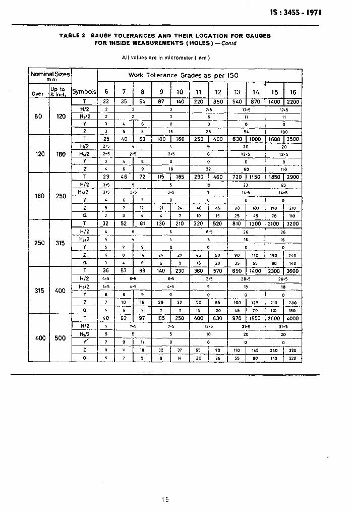
10.2.2 Tolerances on size of working gauges -The tolerances on size of working gauges are based on the fundamental tolerances of grades IT1 to IT7 and are shown in Table 1.
Values of a, y, z. etc, for the gauges are shown in Table 2.
Gauge size for component tolerance ’ T ‘, not included in Table 2 shall be calculated by using the data for the next higher values of ‘ T ’ in the same range.
9

lS:3455- 1971
10.2.3 Tolerances on form of working gauges - The tolerances on form of on the fundamental tolerances of grades IT0 to ITB.and are shown in Table 1,
working gauges are based
10.3 Reference Disks for Gap Gauges
10.3.1 Positions of tolerance zones with respect to the workpiece limits ( shown diagrammatically in Fig. 9).
NO GO limit of workpiece - For nominal sizes up to and including 180 mm the tolerance zone of ihe reference disk is symmetrical to the NO GO limit. For sizes above 180 mm the tolerance zone is symmetrical to a line lying inside the workpiece tolerance zone at a distance a from the NO GO limit.
GO limit of workpiece symmetrical to the z, value.
-The tolerance zone of the reference disk for a new gap gauge is
The tolerance zone of the reference disk for checking wear is located in the following manner:
a) Workpieces of nominal sizes up to and itxluding 180 mm - For tolerance grades IT6 to IT8 the tolerence zone of the reference disk is symmetrical to they, value. For tolerence grades IT9 to IT1 6, y1 is zero and hence the tolerance zone of the reference disk is symmetrical to the GO limit of the workpiece.
b) Workpieces of nominal sizes above 180 mm - For tolerance grades IT6 to IT8 the tolerance zone of the reference disk is symmetrical to the y’, value (u’~ =yl - LYE ). For tolerance grades IT9 to IT1 6 y1 is zero and hence the tolerance zone of the reference disk is symmetrical to the value inside the GO limit of the workpiece.
10.3.2 Tolerances on size of reference disks - The tolerances on size of the reference disks are based on the fundamental tolerances of grades IT1 to IT3 and are shown in Table 1.
Values of a1 y1 2,. etc, for the reference disks are given in Table 3.
Gauge size for component tolerance ‘ T ‘, not included in Table 3 shall be calculated by using the data for the next higher values of ‘ T ’ in the same range.
10.3.3 Tolerances on form of reference disks- The tolerances on form of the reference disks are based on the fundamental tolerences of grades IT1 to IT2 and are shown in Table 1.
10.3.4 Relation between tolerances of gap gauges and their reference disks - The relation between the tolerances HI of the gap gauge and the tolerance of its reference disk H, is as follows:
H1 determines the limits of size of the working size ( see clause 8.4 ) of a gap gauge. The difference between the limits of size given by HI for the gap gauge and by H, for the reference disk represents a safety zone on both sides of Hp to compensate for errors of measurement, in the same way as ct and o(, do for workpieces of diameters over 180 mm, cal ( see Fig. 8 ).
HI and H, are, therefore, symmetri- Therefore, if according to the definition of working size, gap gauges lie outside
the zone HP but within the zone HI, they are still to be regarded as correct.
/+I = manufacturing tolerance of the gap-gauge
Hy = manufacturing tolerame of the reference disk
A = safety zone
FIG. 8 RELATION BETWEEN MANUFACTURING TOLERANCES OF
GAP GAUGES AND OF REFERENCE GAUGES
10

IS : 3455 - 1971
‘IQ.4 Reference Ring and Plug Gauges for Setting Measuring Instruments- The gauges should ba made to tolerances on size and form equal to those for reference disks. The tolerance on size is disposed bilaterally with respect to the appropriate test limit of the workpiece. The size of each gauge should be measured across a diameter halfway through the gauge, and the axial plane in which this diameter occurs and the measured size of the gauge should be marked on the end face of t;le gauge.
11. Formulae for Calculation of Gauge Dimensions
11.1 From the position of the tolerance zones and wear limits in relation to workpiece limits illustrated in Fig. 9, the formulae for calculation of gauge limits can be computed and these are given below. In these formulae, in addition to the symbols given in 10.1, the following are used:
G = higher limit for workpiece, and
K = lower limit for workpiece.
FORMULAE FOR GAUGE DIMENSIONS
T Gauge Nominal Size Size
Up to 180 mm
Gauges Reference Gauge
Above 180 mm ,
Gauges 1 Reference Gauge
Z:F / Basic
$7 ~ Mfg
Size Tol
G-a &Hs i 1
or *H*
2
Basic Size %
Basic M’g Size Tol
~- ---___
*H ?
or *Hs
2
*H Not 2 Provided
_-
-_
-
Inside mea- surements
No Go G
GO (New) K+z Not Provided
K-y+a - - Wear Limit
K-Y
Outside mea- surements
- / G+YI “HP
2- G+yl-=I - Wear
Limit G+YI
-’
Go (New) G-q
_-
*HI 1 G-q 2 1
G-q *HP -5
I--
No Go K K+~I * Hp
I 2 ‘H 2 should only be used when spherical gauges are not used
-
11.2 Sample Calculation - Illustrative examples for the calculation of gauge limits are given below:
Required Gauge Size for 25C9 Plug Gauge
The component tolerances will be + 0.162 + 0.110 >
According to IS : 919-l 963
Corresponding work limits will be G = 25’000 + 0.162 = 25.162 mm K = 25’000 + O-1 10 = 25-l 10 mm
11

IS:3455- 1971
MwlWL SIZE UPTO OOmm
SOMINAL SIZE 4BOVE 160mm
GAUGES FOR INSlOE MEASUREMENTS~M~E! ILLUSTRATIONS FOR GRADES 6 TO 6, ABOVE GRADE 9.Y IS ZERO
ra
ANUFACTURING TOLERANCES PERMlSSl91 y
GAUGES FOR OUTS406 MEASU+?EMENTS ( SHAFTS ). ILLUSTRATITIONS Fop GRADES 5 70 6, ABOVE GRADE 9,Y, IS ZERO
HP r-i- ,
si? FoR TOLERANCE ON WORK- PIECES ( T ) INSIDE OUTSIDE
MEASUREMENTS MEASUREMENTS I
m m nunll FIG. 9 TOLERANCE ZONES OF LIMIT GAUGES AND REFERENCE DISKS
For plug gauges size can be calculated as under:
*NO GO size = G f H/2 = 25.162 f OS002 mm
*GO size new = (K+2)*H/2=(25’110+0’009)*0*002 = 25.119 f 0’002 mm
*GO size wear limit = K - y = 25’110 - 0 = 25*110mm
Required Gauge Size for Snap Gauge 270 + d - 0.05
The component tolerance will be:
.G = 270,000 mm K = 270 - 0’05 = 269.950 mm
Snap gauge size can be calculated as under:
tGO size wear limit = G + yl - a1 = 270*000 + 0*007 - 0*0004 - 270003 mm
’ tG0 size new = (G-q)f~~ - ( 270*000 - 0.008 ) f 0wO06 = 269,992 f 0.006 mm
TN0 GO size = (K -t- a1 ) rt I-$ = ( 269,950 + 0.004 ) f 0.006 269.954 f 0*006 mm
*For actual sizes of plug gauges for standard fits for 1 to 500 mm nomlnal sizes, refer IS :?959-1975 ‘Gauge allowances and manufacturing tolerance for plaln gauges for Inside measurements for IS0 fit sizes (nominal size up to 500 mm) 8.
*For actual sizes of snap gauges and ring gauqes for standard fits from l,to 500 mm nominal sizes, refer IS : 7875-1975 1 Gauge allowances and manufacturing tolerance or plain gauges for outrlde measurements for IS0 fit sizes ( nominal rlze up to M)O mm ) ‘. 12

IS : 3455 - 1971
12. General Requirements
12.1 No recommendations are given in this standard for details of the design of gauges. The technical supply conditions shall conform to IS : 7018-1973 ‘ Technical supply conditions for gauges
The marking and designation of the gauges shall also c&form to the above Indian Standard.
TABLE 1 MANUFACTURING TOLERANCES FOR GAUGES
i -
I ~.. . ..-- IT11 to
IT12
-_._-L-
IT8 to IT10 Tolerance Grade for
Workpiece IT8 IT7 IT4 ITS
I
Forn (ITI
1*
- :orrr UT)
2
2
1
/ I-
Size (ITI
Tolerance Grade for Cy- lindrical Plug Gauges
Tolerance Grade for Cy- lindrical Bar Gauges
Tolerance Grade for Spherical Plug or Disk Gauges
Tolerance Grade for Spherically Ended Rod Gauges
Tolerance Grade for Cy- lindrical Ring Gauges
Tc$;;ze Grade for Gap
Tolerance Grade for Re- ference Disks for Gap bauges
0+
-
-
-
-
-
-
Tolerance Grade for Re- - ference Cylindrical Set- ting Plug Gauges
Tolerance Grade for Refe- ; - rence Cylindrical Setting Ring Gauges
*‘Up to 6 mm diameter only.
-/_- Form Srze (ITI j (ITI -,_
1; 3
! 1 3
1 2
-_ Size
(ITI -
5
-1
Form Size (ITI UT)
o* 1’
- l-
/ - ! -
I
_- Size / Form (ITI (IT) I _I_
Size (IT)
- I -7
-- Size (ITI
2
2
2
Form (ITI
:orm (IT)
5
-
-
-
-
-
-
-
-
I - I -
- -
;_
-- A- -
13

IS:3455-1971
TABLE 2 GAUGE TOLERANCES AND THEIR LOCATION FOR GAUGES
FOR INSIDE MEASUREMENTS ( HOLES )
( Clause 10.2.2 )
All values are in micrometer ( Cm)
Nominal Siid I Work Tolerance Grades as per I SO I
6
18
( Continued)
14
IS : 3455 - 1971
TABLE 2 GAUGE TOLERANCES AND THEIR LOCATION FOR GAUGES FOR INSIDE MEASUREMENTS ( HOLES) - Contd
All values are in micrometer ( pm )
Nomir I
120
180
250
315
400
Grades as per IS0
1 Hs.12 1 ,305 t 3.5 t 3-5 t t 14.5 I 14-s I
I z 151711: I 21 I 24 I 40 I 45 I 80 I loo I 170 I 210 t
al 2 3 4 4 7 10 16 25 45 70 110
T 32 52 1 81 130 1 210 320 1 520 810 1300 2100 3200
HI2 4 6 6 11.5 26 26 I
315 W2 4 4 4 8 16 I6 . Y 5 7 9 0 0 0 0
Z 6 6 14 24 27 45 50 90 110 190 240
a 3 4 6 6 19 15 I 20 35 I 55 90 I 140 .
1 T 1 36 t 57 1 89 i 140 1 230 i 360 1 570 1 890 1 1400 2300 3600 H/2 I 4.5 1 6*5 I 6.5 I 12.5 I 26.5 1 I 23.5 1
4.5 9 18 16
0 0 0 0
Z 7 10 16 26 32 50 6c; 100 125 210 280
a 14 6 1 7 7 1 11 I5 1 30 45 70 110 180
T I 40 63 1 97 155 1 250 400 1 630 970 [ 1550 I2500 1 4000
H/2 1 j 7-5 7.5 13.5 31.5 31.5
500 ““: ; 5 5 10 20 20
9 11 0 0 0 0
2 6 11 ie 32 37 55 70 110 145 240 320
a 5 7 9 9 14 20 35 55 90 140 220 ,

IS : 3455 - 1971
TABLE 3 GAUGE TOLERANCES AND THEIR LOCATIONB FOR GAUGES FOR
OUTSIDE MEASUREMENTS (SHAFTS )
( Clause fO.3.2 )
All values are in micrometer ( pm)
Somir r
her
6
10
18
30
50
Yl 1 1.5 3 0 0 0 0
21 1 2 3 7. 11 28 56
T 8 l! 1 18 27 43 1 70 110 1 180 270 1 430 700 1 1100 HI/~ 1 1*5 2.5 24 I 9 9
18 Hp/2 1 0.6 1 Q6 1 t I 1 I 1.5 I 15 VI Il.51 2 IL I 0 0 0 0 I I I I I I I I
I 21 I 1.5 I 2.5 I 4 I 8 t 16 1 32 i 64 I
T 9 13 I 21 33 52 I 84 130 1 210 330 1 520 840 1 1300 Y/2 l-25 2 3 3 h.5 105 10.5
30 HP/~ 0.75 0.75 1.25 1.25 145 2 2
YI 2 3 L 0 0 0 0 -
I 21 1 l.5 I 3 I 5 1 9 r 19 t 36 I 72 I I
T 11 16 1 25 39 62 1 100 160 1 250 390 1 620 1000 1 1600 Y/2 I.2 5 2 3.5 3.5 5.5 12.5 12.5 _
50 HP/~ 0.75 0.75 1.25 I.25 1.25 2 2 _
Yl 2 3 5 0 0 0 0
1 .Ll 1 L
I T 117
_. . 3.5 6 11 22 12 80
." 19 1 30 46 74 1 120 190 I 300 460 1 740 1200 I 1900 HI/~ 1 1.5 2.5 L L 6.5 15 15
1 1.5 .I.5 1.5 2.5 2.5 80 ,- Hd2 1
Yl 2 3 5 0 0 " 0 0
Zl 2 L * 7 13 25 48 \ 90
( Conm/ed)
16

IS:3455- 1971
TABLE 3 GAUGE TOLERANCES AND THEIR LOCATIONS FOR GAUGES FOR OUTSIDE MEASUREMENTS ( SHAFTS ) - Contd
All values are in micrometer ( pm )
lomrr r
Over
80
‘120
180
250
400
Sizes I I Work Tolerance Grades as per IS0 I
UP to Symbols 5 6 7 8 9 10 11 12 13 14 15 16 8 Incl.
T 15 22 35 54 87 140 510 a70 uoo 2200 b-l.12 2 3 5 5
120
180
T 25 1 40 1 63 1 100 1 160 I 250 I 400 I l
EXPLANATORY NOTE
This standard was originally issued in 1966 with a view to introducing a uniform gauging practice in the country. The method of specifying the tolerance for gauges and also the calculation of gauge limits was based on the proposals then under consideration at the level of Technical Committee lSO/TC 3 Limits and Fits.
In this revision, the gauging practice for inspection of plain workpieces has been elaborated in detail and it is based on Draft IS0 Recommendation No: 1938 IS0 system of limits and fits: Part II Inspection of plain workpieces. In the present version, not only have the tolerances for the gauges been indicated but also the gauging principles have been enumerated and recommendations on the use of gauges for various size ranges have been elaborated, The numerical values given in this standard are expressed in terms of the various grades of tolerances provided for in IS : 919-I 963. These are, therefore, valid for the ISI system of tolerances only. However, all other requirements of a more general nature given in this standard may still be applied as a rule to any system of limits for plain workpieces.
In the earlier version, not only the tolerances for the limit gauges were covered but also certain requirements on the surface finish hardness, etc, of the gauges were incorporated. Since these requirements are now being covered separately in Indian Standard Technical supply conditions for gauges and measuring devices ( under preparafion ), these have been deleted in the present revision.
17
Printed at Dee Kay Printers, New Delhi, India