2949, - Method Statement for Concrete Repair works - Rev B1.pdf

Disclosure to Promote the Right To Information
Whereas the Parliament of India has set out to provide a practical regime of right to information for citizens to secure access to information under the control of public authorities, in order to promote transparency and accountability in the working of every public authority, and whereas the attached publication of the Bureau of Indian Standards is of particular interest to the public, particularly disadvantaged communities and those engaged in the pursuit of education and knowledge, the attached public safety standard is made available to promote the timely dissemination of this information in an accurate manner to the public.
इंटरनेट मानक
“!ान $ एक न' भारत का +नम-ण”Satyanarayan Gangaram Pitroda
“Invent a New India Using Knowledge”
“प0रा1 को छोड न' 5 तरफ”Jawaharlal Nehru
“Step Out From the Old to the New”
“जान1 का अ+धकार, जी1 का अ+धकार”Mazdoor Kisan Shakti Sangathan
“The Right to Information, The Right to Live”
“!ान एक ऐसा खजाना > जो कभी च0राया नहB जा सकता है”Bhartṛhari—Nītiśatakam
“Knowledge is such a treasure which cannot be stolen”
“Invent a New India Using Knowledge”
है”ह”ह
IS 2949 (1992): Engineering metrology - Plain V-blocks forinspection purposes [PGD 25: Engineering Metrology]


IS 2949 : 1992
qm?aT WTT
-$I?~~ WCT fasrr;r - f;rftwoT sstwi? + fT$ TV? pm% - fs!rf+
( FTT ‘5;r*w ) Indian Standard
ENGINEERINGMETROLOGY- PLAINV-BLOCKSFORINSPECTION
PURPOSES- SPECIFICATION
( Second Revision ) ~~~
First Reprint AUGUST 1997
UDC 531’711’51
@ BIS 1992
BUREAU OF INDIAN STANDARDS MANAK BHAVAN, 9 BAHADUR SHAH ZAFAR MARG
NEW DELHI 110002
February 1992 Price Group 5

Engineering Metrology Sectional Committee, LM 05
FOREWORD
‘This Jrdizn Standard ( Secord Revision > was adcpted by the Bureau of the draft finalized by the Engineering Metrology Sectional Committee had Light Mechanical Engineering Division Council.
Indian Standards, after been approved by the
This standard was originally published in 1964 ard its first revision was brought out in 1974.
The ccmmittee responsible for publication of this standard decided to take up second revision of this standard to include double V-blccks and to align it with DIN 2274 : 1981 ‘V-blocks for insnection nuruoses, desinD reauirements’, issued bv Deutsches Jnstitut fiir Normung ( Germany ). fhimajor highlights of this revision are: .
a) DIN 2274 : 1981 gives details of V-blocks for inspection purposes thus meant for V-blocks for ir spection purposes only.
b) The original standard included two grades based on material included in earlier standard specified cast iron V-blocks which are purposes atd hence they are deleted in this edition. These may standard.
cl
specification. Grade B not used for inspection be covered by separate
Two angles of Vee, that is SO0 and lC8” are given in this standard. In addition to Vee angle
only. This standard is
of 90” which is till now almost exclusively used, 108” is also specified since 108” is geometri- cally advantageous to use. For roundness tests 108” is useful for almost all form deviations and all practically occurring uniform wave error can be identified ( excepting 9 sided uniform wave error ). Thus a special significance is attached to the Vee angle 108” for testing centreless ground components.
d) Three grades of V-blocks are specified, based on accuracies.
e) Since the standard is meant only for V-blocks for inspection purposes, details of clamps are given in Annex A.
f) Double level sirgle groove V-blocks are included.
g) Tolerances for various parameters have been specified as per DIN 22/q : 1981.
h) The determination of ranges for workpiece diameter acd of the design dimension is done under presupposition that a satisfactory tangential seating of the workpiece in V-block is assumed taking into consideration ary edge sloping. The edge slope rarge and the groove dimension were determined particularly for the accuracy Grade 0 with respect to maximum possible workpiece diameter racge.
j) Fcr testing V-blccks, many tasic prirciples and methods are possible so that only one methcd cannot be spccifed for ar y parameter. Only one method is given in Annex B and is restricted to gereral statements and cne example orly. It is not the only specified method for verifying an appropriate parameter. Mary components are included in the measure- merts. However, for evaluating purposes it can be stated that relevant tolerance will not be exceeded if any direction is tested accordirg to this example and is observed less than or equal to specified tolerance.

. -
IS 2949 : 1992
Indian Standard
ENGINEERING METROLOGY - PLAIN V-BLOCKS FOR INSPECTION
PURPOSES - SPECIFICATION
( Second Revision ) 1 SCOPE
1.1 This standard covers the requirements of V-blocks to be used as individual V-blocks or in pairs for inspection purposes. The standard also gives th? dimensions of clamps to be used with V-blocks.
1.2 Use of V-Blocks
V-blocks for inspection purpose are preferably used for aligning, marking and testing of cylindrical and V-shaped workpieces.
2 REFERENCES
The following Indian Standards are necessary adjuncts to this standard:
IS No. Title 1501 Methods for Vickers hard-
( Part 1 ) : 1984 ness test for metallic materials : Part 1 HV 5 to HV 100 ( second revision )
7018 Technical supply conditions ( Part 1 ) : 1983 for gauges : Part 1 General
8000 Geometrical tolerancing on ( Part 1 ) : 1985 technical drawings : Part 1
Tolerances of form orien- tation, location and run-out and appropriate geometrical definitions ( first revision )
3 NdMENCLATURE AND DEFINITIONS
3.1 The nomenclature illustrated in Fig. 1, along with definitions given in 3.1 to 3.7 shall apply.
FLANKS OF VEE FLANKS OF VEE
SINGLE VEE. SINGLE VEE SINGLE GROOVE V-BLOCK DOUBLE GROOVE V -BLOCK
C3L’BLE VEE SlttrJLE C_QOOVE V-BLOCK

IS 2949:1992
3.2 Matched Pair
Two V-blocks’ of the same nominal size and same grade of accuracy.
3.3 Working Sorfaces
Flanks of Vees, base, end faces, top faces and side faces of V-block.
3.4 Geometrical Tolerances
c8rritions shall be as per IS 8000 ( Part 1 ) :
3.5 Matching Tolerance
Applicable to matched V-blocks only. It is the difference in height above the base of the V-blocks to the top cylinders contacting near the bottom acd near the top of Vee surfaces res- pectively of two matched V-blocks ( see Fig. 2 ).
3.6 Minimum and Maximum Size of Work- pieces
The minimum and maximum diameters of cylindrical w orkpiece that can be accommo- dated on the V-block ( see Fig. 2 ).
3.7 Axis of V-Block
The line of intersection of the planes of flanks of Vee.
4 DESIGN AND TYPE OF V-BLOCK
4.1 Design
4.1.1 Different designs as given below are possible:
a) With 1 Vee or 2 Vees facing one another,
b) V-angle of 90” or IOS”, and
c) With or without side and front faces as contact surfaces.
4.2 Type of V-Block
V-blocks may have single or double Vee and single or double grooves as per Fig. 1.
4.2.1 Type Al with single Vee and side and end faces as contact surfaces.
4.2.2 Type A2 with two Vees and side and end faces as contact surfdces.
4.2.3 Type Bl with single Vee and side and end faces not intended as contact surfaces.
4.2.4 Type B2 with two Vees and side and end faces not intended as contact surfaces.
For designs of V-block of Type Bl and B2, the side and front faces are not intended as contact surfaces.
MINIMUM DIA OF
\ WORKPIECE
MATCHING TOLERANCE: DIFFERENCE IN Z, AND Z2
MAXIMUM DIP OF \WORKPIECE
MATCHING TOLERANCE = DIFFERENCE IN Z, AND ZL
FIG. 2 MATCHING TOLERANCE OF MATCHED V-BLOCKS
2

IS 2949 : 1992
5 GRADES OF V-BLOCKS in IS 7018 (Part 1 ) : 1983.
V-Blocks shall be of three grades, namely, 6.2 Hardness Grade 0, 1 and 2. V-blocks shall be hardened to hardness value of 6 MATERIAL AND HARDNESS 650 f 100 HV [ see IS 1501 ( Part 1 ) : 1984 1.
6.1 V-blocks shall bz made from suitable quality 7 DIMENSIONS
of steel selected from the grades of steels given Dimensions shall be as given in Tables 1 to 4.
Table 1 Dimensions of Type Al and Bl V-Blocks, V-Angle cx = 90”
( Clauses 7 and 11.2 ) All dimensions in millimetres.
a
END FACE = = =-l-x-_---Z.--z-z-z-_
_----- __--_-zz===- -
‘width 1
40 50 40 25.292 1.2 24 40 75 40 24.726 1’5 24
40 100 40 24.726 2.2 24
50 150 45 26.191 2.9 25 70 200 55 28,483 3.1 27 85 250 65 33.180 3.8 32
100 300 75 37,877 4.5 36
Le;gth Height r--h_-Y
h h Min
Groove Dimensions c-_-_--1
6, 11, Max
Diameter of Workpiece r--------- h--_-_-_--~
For Grade 0 For Grades 1 and 2 C_--h___~ c__---_ Min Max Min Max
2.6 41.0 4 40 3.5 42.0 6 40
4.4 42.2 7 40
5.4 52.1 8 50 6.7 73.0 10 70
7.7 88.0 11 85 8.7 ‘02.9 12 100
NOTES
1 The smallest diameter of workpiece for which a V-block may be used is obtained from the groove width ‘6%’ taking into consideration the distance ‘s’ according to 8.3 and the tolerance of symmetry t, of the groove.
2 The ligure is indicative of dimensions only and does not specify design features.
1) h, is the theoretical dimension for the height of the lines of intersection of the mounting surfaces taking Into consideration the maximum workpiece diameter, the constructional dimension and the distance ‘s’. For h,, there is no tolerance, except that it shall be ensured that hs is greater than h,.
3

IS 2949 : 1992
Table 2 Dimcosions of Types Al and Bl V-Blocks, V-Angle o = 108" ( Clauses 7 and 11.2)
All dimensions in millimetres.
Length Height Groove Dimensions Diameter of Workpiece ’ I
7-*---‘ r____h_-_-~ r---.--__h_._____ _
M/n h3 ba h For Grade 0 For Grades 1 and-?
h4u.x r__h_--, t--- h___> hIin Max hfifl MCIX
30 30 30 12.124 0.9 22 2.1 31.3 4.5 30 40 50 40 30.989 1.2 30 3.3 41.3 5 40 40 75 40 30’519 1.7 30 4.7 43.0 8 40 40 lC0 40 30’519 2’3 30 5.7 43.0 9 40 50 150 45 33.383 4.3 32 7.6 53.0 11 50 70 200 55 38.584 3.7 37 9.4 71.1 14 70 85 250 65 45.381 3.4 44 10.5 89.1 15 85
100 300 75 ‘2.178 4.9 51 11.5 101.1 16 100
NOTES
1 The Smallest dlameter of workpiece for which n V-block may bc used is obtnincd from the groove width a& taking into consideration the distance ‘s’ according to 8.3 and the tolerance of symmetry f, of the groove.
2 The figure is indicative of dimensionc only and dots not Specify design features.
1) /I, js the theoretical dimension for the hcl, ‘*,ht of the lines of intersection of the mounting surfaces taking into consideration the maxinlum workpiccc tliamcrcr, lhc conslrrlCtiOn;l~ dimensions and the distance ‘s’. For 11~. there is no tolerance, except that. it shall bc ensured th:lt If3 is greater than 1)~.

IS 2949 : 1992
Table 3 Dimensions for Types A2 and B2 V-Blocks, V-Angle a = 90”
( Clauses 7 and 11.2 )
All dimensions in millimetres.
Width b,
Mill
40 50 40 32.363 1.2 31 40 75 40 31.798 1.5 .31 40 100 40 31.798 2.2 31 50 150 50 40.030 2.9 39 70 200 70 55.858 3.1 54 85 250 85 67.322 3.8 66
100 300 100 80.555 4’5 79
. ----- _==---_-=rz_ pjqq=-
- ----------- ------_-__-_ -IlltsJAt
[/IF
Lelngth Height Groove Dimensions r-- h--y y--_h--->
hr h, ba h, Max
Diameter of Workpiece ‘d’ (-_---_----h-_-_
For Grade 0 ----7
For Grades 1 and 2 (.--_*_-~ Mitl Max
r------_y Min Max
2.6 21.0 4 20 3.5 22.1 6 20 4.4 22.1 7 20 5.4 27.1 8 25 6’7 37.9 10 35 7.7 48.0 11 45 8.7 52.9 12 50
NOTES
1 The minimum diameter of workpiece for which a V-block may be used is obtained from the groove width b, taking into consideration distance ‘s’ as per 8.3 and the tolerance of symmetry t, of the groove.
2 The figure is indicative of dimensions only and does not specify design features.
1) h, is the theoretical dimension for the height of the lines of intersection of the smaller Vee takin;:;: consideration the maximum workpiece diameter, the constructional dimensions and the distance ‘s’. there is no tolerance except that h, is greater than hh.
0
5

IS 2949 : 1992
Table 4 Dimensions for Types A2 and B2 V-Blocks, V-Angle a = 108” ( Clauses 7 and 11.2 )
All dimensions in millimetres.
w;dtb 1
30 30 30 26,372 0.9 25 40 50 40 35.259 1.2 34 40 75 40 34.789 1.7 33 40 100 40 34’789 2.3 33 50 150 50 43.721 3.4 42 70 200 70 61.057 3.7 60 85 250 85 73.922 4.3 72
100 300 100 87.854 4.9 86
__---- = = = = - - __-- ____------ -- ---- __-_ i-I 1
a
Length I
Height r--*e7
h, h, Min
Groove Dimensions r-__-h__-_-7
b, h, Max
Diameter of Workpiece ‘d’ r-______-h______
For Grade 0 For Grades 1 and 2 /---A__ r.---h.__-_ Min Max Min Max
2.7 16’1 4-5 IS 3.3 21.3 5 20 4.7 23’0 8 20 5.7 23.0 9 20 7.6 28’0 11 25 9.4 39.1 14 35
IO.5 49.1 I5 45 11.5 54’1 16 50
NOTES
1 The minimum diameter of workpiece for which a V-block may be used is obtained from the groove width b, taking into consideration distance ‘.Y ’ as per 8.3 and the tolerance of symmetry I, of the groove.
2 The figure is indicative of dimensions only and does not specify design features.
‘) hs is the theoretical dimension for the height of the lines of intersection of the smaller Vee taking into consideration the maximum workpiecc dramcrer, the constructional dimensions and the distance ‘J’. there is no tolerance except that h, i\ gre.htcr than /I,.
For h,

IS 2949 : 1992
8 TOLERANCES OF FORM AND POSITION
8.1 Tolerances of form and position of V-block shall be as specified in Table 5. Following terminology gives designations of symbols in Table 5. The symbols are also illustrated in figure in Tables 1 to 4.
fp - Symmetry tolerance of the mounting surface to the mid plane of the parallel
lateral surface.
ta - Parallelism tolerance of lateral surface to each other.
ta - Perpendicularity tolerance of the front surface to the reference surface A.
t1 - Flatness tolerance of base surfaces A and D and of the mounting surfaces.
tr - Parallelism tolerance of the lines of contact of a geometrically ideal cylinder with the mounting surfaces to the reference surface A or D. The diameter of this cylinder should be between minimum and maximum workpieces sizes for the V-block.
t3 - Parallelism tolerance of the lines of contact of a geometrically ideal cylinder with the mounting surfaces to the mid plane of a parallel lateral surfaces. The diameterofthe cylind;r should be within minimum and maximum lrmits of work- piece diameter for the V-block.
17 - Perpendicularity tolerance of the front surface to the reference surface A.
te - Symmetry tolerance of the groove to the mid plane of mounting surfaces.
For V-blocks with 108” included angle only tolerances fr, t, and t3 arc valid. For these the lateral surfaces and front faces arc not intcndcd as contact surfaces, hence remaining tolerance requirements are not applicable.
8.2 Surface roughness of Type Al and Bl V-blocks shall be as shown in FIN. 3 and that of Type A2 and B2 V-blocks as shown in Fig. 4. Surface roughness on clamping grooves shall be N9.
Fra. 3 SURI’ACrJ ROUGHNESS ON V-BLOCKS - Types Al AND BI
Fro. 4 SURFACBROUGHNESSON V-BLOCKS -TYPES A2 AND B2
7

I
IS 2919 : 1992
8.3 Edge Sloping
Edge sloping up to a distance ‘s’ as mentione,d in Table 6 from the edges of all the surf%:s IS permissible.
8.4 Matched Pairs
Matched pairs are manufactured together or SO selected that the test cylinder of any desired diameter does not indicate larger difference in height than ‘Ah’ in the given range ( Table 7 ) when the mounting is done on both the V-blocks.
8.5 A recommended method of testing V-block is given in Annex B.
9 DESIGNATION
V-blocks shall be designated as follows:
V-block
IS 2949 - 50 X 150 - Al - 1 - P
_ Pair ( omit- ted in case of single block
Accuracy grade
Type
Width x length
Table 5 Tolerances for V-Blocks
( Chse 8.1 ) lo GENERAL REQUIREMENTS
All sharp edges shall be removed. The V-blocks
YZde Vee Form and Positional Tolerance in pm shall be demagnetized and shall be free from
Angle ~~~~~~__~~-----~-~ V-Block Tale- t, ra. t3, f,, ?a, t7 ts
other metallic/non-metallic inclusions, porosity
rance ts and other injurious defects.
I 0 il’ 2+&-
h 3+zK 2+im-
200 11 CLAMPS
I f2’ 4+250 6+
I 4+& 400
11.1 The standard covers requirements of 1 100 V-block for inspection purposes only. Hence
_I: 2’ 10 f & 12 + & 10 +& clamps are generally not required. However a
2 400 table showing sizes of clamps is included in Annex A.
NOTE - Values of ‘I’ and ‘hl’ are in mm. 11.2 Clamps if supplied shall be made from
Table 6 Permissible Edge Sloping suitable quality cast iron which will make the clamps sufficiently robust within the sizes given
( Clause 8.3 ) in Tables 1 to 4.
Grade s - 12 MARKING #-----------
&lock 1 G 50 A_--___--_-~
50 < I < 150 150 < I g 300 0 0.3 0.5 1.5
12.1 The V-blocks shall be legibly and perma-
1 0,8 1.6 2.5 nently marked with type, width, length, grade
2 0.8 I.6 2.5 of V-block, angle of Vee and letter S for single and in case of matched pairs, with the letter P.
Table 7 Permissible Height Difference Ah 12.2 The marking may also include manu- for Matched Pairs facturer’s identification marks, Sl No. etc.
( Clause 8.4 ) 13 PACKING
Grade of All V-Block pm
0 2 During the storage and transit, all finished
I 4 surfaces of V-blocks shall bc protected against
2 8 climatic conditions by covering with a sult:ibJe corrosion preventive preparaiion.
8

IS 2949 : 1992
ANNEX A ( Foreword, and Clause Il. 1 )
DIMENSIONS OF CLAMPS WITH SCREWS
A-l DIMENSIONS OF CLAMPS AND SCREWS
Dimensions of clamps and screws shall be as given in Table 8.
Table 8 Dimensions of Clamps and Screws
KNURLING IS)‘03
r-- POSITION OF KNURLED HEAD WHEN MAXIMUM CYLINDER IS CLAPyPED/
I 7
I POSITION OF KN” HE40 WHEN YIN CYLINDER IS CLA
ti 03
c
0
61 Hl L R Z H A B
30 35 5 25 5 85 M8xl 14 40 45 5 35 5 95 M8xl 14
50 45 5 35 5 95 M8xl 14 70 75 8 55 5 125 M8x1 14
85 90 8 55 5 140 M8xl 14
100 110 14 85 10 195 M8x1 14
IS 2949 : 1992
ANNEX B ( Foreword, and Clause 8.5 )
METHOD OF TESTING V-BLOCKS
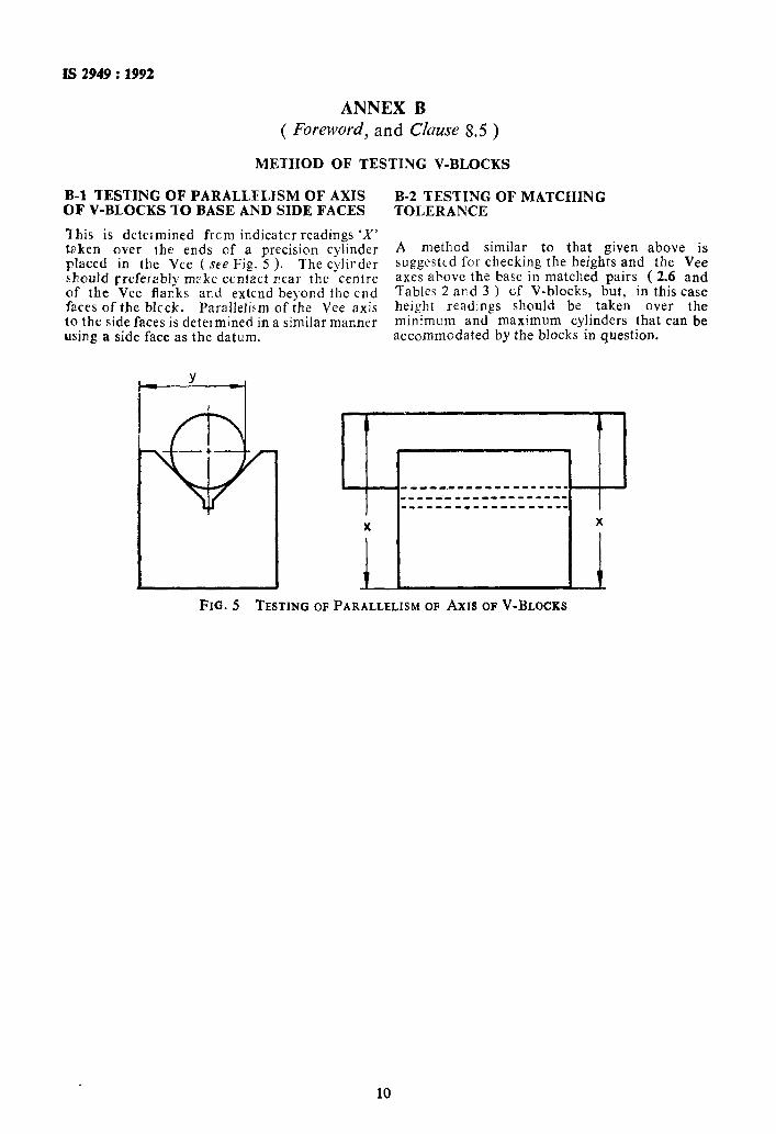
B-l TESTING OF PARALLELJSM OF AXIS OF V-BLOCKS TO BASE AND SIDE FACES
This is determined frcm indicator readings ‘X’ taken over the ends of a precision cylinder placed in the Vee ( see Fig. 5 ). The cylirdcr should preferably meke ccntact rear the centre of the Vee flanks ard extend beyond the end faces of the blcck. Parallelism of the Vee axis to the side faces is determined in a similar manner using a side face as the datum.
B-2 TESTING OF MATCHING TOLERANCE
A method similar to that given above is suggested for checking the heights and the Vee axes above the base in matched pairs ( 2.6 and Tables 2 and 3 ) of V-blocks, but, in this case height readings should be taken over the minimum and maximum cylinders that can be accommodated by the blocks in question.
1 1 P 7
~_____.L_____--_----I
_________----------
_______m___-m------
X X
1 FIG. 5 TESTING OF PARALLELISM OF Axrs OF V-BLOCKS
10

Bureau of Indian Standards
BIS is a statutory institution established under the Bureau of Indian Standards Act, 1986 lo promote harmonious development of the activities of standardization, marking and quality certification of goods and attending to connected matters in the country.
Copyright
BIS has the copyright of all its publications. No part of these publications may be reproduced in any form without the prior permission in writing of BIS. This does not preclude the free use, in the course 01 implementing the standard, of necessary details, such as symbols and sizes, type or grade designations. Enquiries relating to copyright be addressed to the Director (Publication), BIS.
Review of Indian Standards
Amendments are issued to standards as the need arises on the hasis of comments. Standards are also reviewed periodically; a standard along with amendments is reaffirmed when such review indicates that no changes are needed; if the review indicates that changes are needed, it is taken up for revision. Users of Indian Standards should ascertain that they are in possession of the latest amendments or edition by referring to the latest issue of ‘BIS Handbook’ and ‘Standards Monthly Additions’.
This Indian Standard has been developed from Dot: No. LMD 05( 3745 )
Amend No.
Amendments Issued Since Publication
Date of Issue Text Affected
Headquarters: BUREAU OFINDIANSTANDARDS
Manak Bhavan, 9 Bahadur Shah Zafar Marg, New Delhi 110002 Telegrams: Manaksanstha Telephones: 323 0131,323 33 75,323 94 02 (Common to all offices)
Regional Offices: Telephone
Central :
Eastern :
Northern :
Southern :
Western :
Branches :
Manak Bhavan, 9 Bahadur Shah Afar Marg NEW DELHI 110002
323 76 17,323 38 41
l/14 C.I.T. Scheme VII M, V.I.P. Road, Maniktola CALCUTTA 700054
SC0 335-336, Sector 34-A, CHANDIGARH 160022
337 84 99,337 85 61 337 86 26,337 9120
{ 60 38 43 60 20 25
C.I.T. Campus, IV Cross Road, C!IENNAI 600113 {
235 02 16,235 04 42 2351519,2352315
Manakalaya, E9 MIDC, Marol, Andheri (East) MUMBAI 400093
AHMADABAD. BANGALORE. BHGPAL. .BHUBANESHWAR. COIMBATORE. FARIDABAD. GHAZIABAD. GUWAHATI. HYDERABAD. JAIPUR. KANPUR. LUCKNOW. NAGPUR. PATNA. PUNE. THIKUVANANTHAPURAM.
{ 832 92 95,832 78 58 832 78 91,832 78 92
F’riat6d at Simco printing Press, Delhi. India