IS 15398 (2003): Software for Computers in the Safety ...
53
Disclosure to Promote the Right To Information Whereas the Parliament of India has set out to provide a practical regime of right to information for citizens to secure access to information under the control of public authorities, in order to promote transparency and accountability in the working of every public authority, and whereas the attached publication of the Bureau of Indian Standards is of particular interest to the public, particularly disadvantaged communities and those engaged in the pursuit of education and knowledge, the attached public safety standard is made available to promote the timely dissemination of this information in an accurate manner to the public. इंटरनेट मानक “!ान $ एक न’ भारत का +नम-ण” Satyanarayan Gangaram Pitroda “Invent a New India Using Knowledge” “प0रा1 को छोड न’ 5 तरफ” Jawaharlal Nehru “Step Out From the Old to the New” “जान1 का अ+धकार, जी1 का अ+धकार” Mazdoor Kisan Shakti Sangathan “The Right to Information, The Right to Live” “!ान एक ऐसा खजाना > जो कभी च0राया नहB जा सकता ह ै” Bhartṛhari—Nītiśatakam “Knowledge is such a treasure which cannot be stolen” IS 15398 (2003): Software for Computers in the Safety Systems of Nuclear and Radiation Facilities [LITD 8: Electronic Measuring Instruments, Systems and Accessories]
Transcript of IS 15398 (2003): Software for Computers in the Safety ...

Disclosure to Promote the Right To Information
Whereas the Parliament of India has set out to provide a practical regime of right to information for citizens to secure access to information under the control of public authorities, in order to promote transparency and accountability in the working of every public authority, and whereas the attached publication of the Bureau of Indian Standards is of particular interest to the public, particularly disadvantaged communities and those engaged in the pursuit of education and knowledge, the attached public safety standard is made available to promote the timely dissemination of this information in an accurate manner to the public.
इंटरनेट मानक
“!ान $ एक न' भारत का +नम-ण”Satyanarayan Gangaram Pitroda
“Invent a New India Using Knowledge”
“प0रा1 को छोड न' 5 तरफ”Jawaharlal Nehru
“Step Out From the Old to the New”
“जान1 का अ+धकार, जी1 का अ+धकार”Mazdoor Kisan Shakti Sangathan
“The Right to Information, The Right to Live”
“!ान एक ऐसा खजाना > जो कभी च0राया नहB जा सकता है”Bhartṛhari—Nītiśatakam
“Knowledge is such a treasure which cannot be stolen”
“Invent a New India Using Knowledge”
है”ह”ह
IS 15398 (2003): Software for Computers in the SafetySystems of Nuclear and Radiation Facilities [LITD 8:Electronic Measuring Instruments, Systems and Accessories]


IS 15398:2003
Indian Standard
SOFTWARE FOR COMPUTERS IN THE SAFETYSYSTEMS OF NUCLEAR AND RADIATION
FACILITIES
ICS 27.120.20,35.080
@ BE3 2003
BUREAU OF IN DIAN STANDARDSMANAK BHAVAN, 9 BAHADUR SHAH ZAFAR MARC
NEW DELHI 110002
December 2003 Price Group 14

Nuclear Instrumentation Sectional Committee, LTD 26
FOREWORD
This Indian Standard was adopted by the Bureau of Indian Standards, after the draft finalized by the NuclearInstrumentation Sectional Committee had been approved by the Electronics and Telecommunication DivisionCouncil.
Computer systems are extensively used for on line monitoring of the reactor core against blockage of coolantflow, on line power regulation, fuel handling operation, supervision of process parameters against safetythresholds, event sequence analysis, measurement of.radiation level, etc. The basic principles for the design ofnuclear instrumentation as specifically applied to the safety systems of nuclear and radiation facilities have beeninterpreted in existing standards with reference to hardwired systems as the ‘Safety Guide 50-SG-D2’ of theI.A.E.A.
This standard has been developed to interpret these principles for the utilization of digital systems —multi-processor distributed systems as well as larger scale central processor systems — in the safety systemsof nuclear facilities. The other process plants may find use of this standard in the design and use of their computerbased systems. It discusses the software system principles and requirements and should be read in conjunctionwith IS 15399:2003 ‘Hardware for computers in the safety system of nuclear and radiation facilities.’
This standard may also be useful as a guide for other computer systems requiring real time applications.
Aspects for which special recommendations have been produced, due to the unique nature of computer systemsand their software are:
a) Established hardware criteria as far as they affect the software, taking careful account of the high degreeof interdependency between hardware and software;
b) A general approach to software development to assure the production of the highly reliable softwarerequired,
c) A general approach to software verification and computer system validation; and
d) Procedures for software maintenance, modification and configuration control.
While preparing this standard, assistance has been derived from IEC 60880 (1986) ‘Software for computers inthe safety systems of nuclear power stations’ issued by the International Electrotechnical Commission.
The composition of the Committee responsible for formulation of this standard is given in Annex G.

IS 15398:2003
Indian Standard
SOFTWARE FOR COMPUTERS IN THE SAFETYSYSTEMS OF NUCLEAR AND RADIATION
FACILITIES1 SCOPE
1.1 Tlis standard is applicable to highly reliablesoftware required for computers to be used in thesafety systems of nuclear facilities for safety functions— Class 1 functions according to IS 12772:2003‘Application of computers to nuclear reactorinstrumentation and control (first revision)’. Thisincludes the safety actuation systems, the safetysystem support features and the protection systems.
1.2 This standard covers requirements for each stageof software generation, including design,development, qualification and operation as well asthe documentation for each stage of the softwaregeneration for the purpose of achieving highly reliablesoftware. An acceptable approach to the developmentand content of the software requirements is given inAnnex A.
The principles applied in developing theserequirements include:
a) Best available practice;b) Top-down design methods;C) Modularity;d) Verification of each phase;e) Clear documentation;f) Auditable documents; andg) Validation testing.
1.3 Additional guidance and information on how tocomply-with the requirements of the main part of thisstandard is given in Annex B to Annex F.
1.4 If practices differing from those of the Annexesare used, they shall be documented and auditableaccording to the requirements of the main part of thisstandard.
2 REFERENCES
The following standards are necessary adjuncts to thisstandard:
IS No.
IS 12772:2003
IS 15399:2003
Title
Application of computers to nuclearreactor instrumentation and control(first revision)
Hardware for computers in thesafety system of nuclear andradiation facilities
3 TERMS AND DEFINITIONS
For the purpose of this standard, following definitionsshall apply.
3.1 Application Programme — A computerprogramme that performs a task related to the processbeing controlled rather than the functioning of thecomputer itself.
3.2 Code Compaction — The purposeful reductionin memory size required for a computer progratnmeby the elimination of redundant or extraneousinstructions.
3.3 Computer — A programmable functional unitthat consists of-one or more associated processingunits and peripheral equipment, that ‘is controlled byinternally stored programmed and that can performsubstantial computation, including numerousarithmetic operations or logic operations, withouthuman intervention during a run.
NOTE — A computer may Ix a stand-atone unit or may consistof severat intercomected units.
3.4 Computer Programrm! — A set of ordered.instmctions and data that specify operations in a formsuitable for execution by a digital computer.
3.5 Computer System — A system consisting of oneor more computers (comprising hardware as well assoftware) collectively forming a functional unit of aninstrumentation and control system.
3.6 Data — A representation of facts, concepts orinstructions in a formalized manner suitable forcommunication, interpretation or processing by acomputer.
3.7 Defence in Depth — Provision of multiple levelsof protection for ensuring safety of workers, the publicorthe environment.
3.8 Diversity — Existence of different means ofperforming a required function (for example, otherphysical principles, other ways of solving the sametask).
3.9 Fault Tolerance — The built-in capability of asystem to provide continued correct execution in thepresence of a limited number of hardware or softwarefaults.
1

IS 15398:2003
3.10 Graceful Degradation — Stepwise reductionof system functions in response to detected failureswhile essential functions are maintained.
3.11 Initialize — To set counters, switches,addresses, or contents of storage devices to zero orother starting values at the beginning of, or atprescribed points in, the operation of a computerprogramme.
3.12 Integration Tests — Tests performed duringthe hardware/software integration process prior tocomputer system validation to verify compatibility ofthe software and the computer system hardware.
3.13 Procedure — A portion of a computerprogramme which is named and which perform aspecific task.
3.14 Redundancy — Provision of alternative(identical or diverse) elements or systems so that anyone can perform the required function regardless of thestate of operation or failure of any other.
3.15 Single Failure — A random failure, whichresults in the loss of capability of a component toperform its intended safety function. Consequentialfailures resulting from a single random occurrence areconsidered to be pmt of the single failure.
3.15.1 Single Failure Criterion — A criterion appliedto a system such that it is capable of performing itssafety task in the presence of any single failure.
3.16 Software — Programmed, procedures, rules andany associated documentation pertaining to theoperation of a computer system.
3.17 “Software Life Cycle — The period of time thatstarts when a software product is conceived and endswhen the product is no longer available for use. Thesoftware life cycle typically includes a requirementsphase, design phase, implementation phase, test phase,installation and check-out phase, operation andmaintenance phase.
3.18 Software Modification — Changes of alreadyagreed documents leading to a change to theexecutable code or its data.
3.19 Software Modularity — The software attributethat provides a structure of highly independentcomputer programme units that are discrete andidentifiable with respect to translating, testing andcombining with other units.
3.20 Validation — The test and evaluation of theintegrated computer system (hardware and software)to ensure compliance with the functional, performanceand interface requirements.
3.21 Verification — The process of determiningwhether or not the product of each phase of the digital
computer system development process fulfils all therequirements imposed by the previous phase.
3.22 Avaihhility — The ability of an item to be in astate to perform a required function under givenconditions at a given instant of time or over a giventime interval, assuming that the required externalresources are provided.
3.23 Component
a)
b)
Hardware — Items from which the system isassembled (for example, integrated circuits,resistors, capacitors, wires, connectors, tran-sistors, switches, etc).So~are — A basic part of a progmmme.
3.24 Design — The theoretical -work which leadstowards a system requirements specification.
3.25 Development — The experimental, testdemonstration work which is intended to prove thesuccess of any pints of the design whose performancecannot be ensured by theoretical work alone.
3.26 Maintainabfity — The probability that a givenactive maintenance action to an item under givenconditions of use can be carried out within a statedtime interval -when the maintenance is performedunder stated conditions and using stated proceduresand resources.3.27 Maintenance — The combination of alltechnical and administrative actions, includlngsupervision actions, intended to retain an item in, orrestore it to, a state in which it can perform a requiredfunction.
3.28 Module — Any assembly of interconnectedcomponents which constitutes an identifiable device,instrument or piece of equipment. A module can beremoved as a unit and replaced with a spare. It hasdefinable performance characteristics which permit itto be tested as a unit. A module could be a caFL a drawout circuit breaker or any other sub-assembly of alarger device, provided it meets the requirements ofthis definition.
3.29 Qualified Life — The period of time for whichsatisfactory performance can be verified for aspecified set of operating conditions.
3.30 Reliability — The probability that a failurewhich causes deviation from the required output bymore than specified tolerances, in a specificenvironment, does not occur during a specifiedexposure period.
3.31 Sub-System — A division of a system that initself has the characteristics of a system.
3.32 System — A set of interconnected elementsconstituted to achieve a given objective by performinga specified function.
‘L

4 PROJECT STRUCTURE
Any project will normally be divided up into a numberof phases. Each phase is to some extent self-containedbut will depend on other phases and will, in its turn, bedepended on by others. These phases are informallyrecognizable by the specific activities pertinent tothem.
For safety related applications, these phases shall beformalized and none of the identified phases shall beomitted.
4.1 General
The following general factors determine the activitiesin implementation of a project.
4.1.1 The whole software life cycle shall beconsidered.
4.1.2 Each phase of the software life cycle shall bedivided into elementary tasks with a well-definedactivity for each of them.
4.1.3 Every product shall be systematically checkedafter each phase (see B-5.7).
4.1.4 The tasks of quality assurance should be rungenerally in parallel with the other tasks of the lifecycle.
4.1.5 Each phase shall include generation of theappropriate documents (see F-3).
4.1.6 Each phase shall be systematically terminatedby a critical review. Critical reviews forma major partof the verification process of the software project(see 6).
4.1.7 Every verification step or critical review shallresult in a report on the analysis performed, theconclusions reached and the resolutions agreed. hisreport shall be included in the documentation.
4.1.8 A list of documents required as a minimumthrough the software life cycle is given in Annex F.
4.2 Software Quality Assurance Plan
A quality assurance plan shall exist or be establishedat an early stage either as a part of the computer systemspecification (see 4) or.as a companion document.
Although the whole of this standard and its annexescan be considered as a quality assurance plan for safetyrelated software, special quality assurance plans maybe adopted for individual product phases or particularsoftware components according to organizationalstandards.
These plans should address all quality assuranceprocedures required during all phases of the softwarelife cycle.
IS 15398:2003
5 SOFTWARE REQUIREMENTS
5.1 General
5.1.1 The software requirements (see M2 of F-1and F-3) shall be derived from requirements of thesafety systems and are part of the computer systemspecification. The computer system specification is adescription of the combined hardware/softwaresystem and states the objectives and functionsassigned to the computer system. The safety criticaland safety related functions shall be clearly identifiedin the requirement specification document.
5.1.2 The software requirements describe theproduct, not the project. They shall describe what hasto be done and not how it has to be done. Anacceptable approach to the development and contentof the soft-warerequirements, which is consistent withthis clause, is given in Annex A.
5.1.3 Whereas the main -purpose of the softwarerequirements document is to form the basis forsoftware development, the licensing aspects shouldnot be neglected. Therefore, it may contain aspects ofminor importance to software design which are,however, a background for licensing. Such aspectsmay be:
a)b)
c)
Risk considerations;Recommendations for functions or engineeredsafety features; andOther items that provide the background forspecific requirements.
5.1.4 The software functional Requirementsrepresentan expansion of the functions which are assigned tothe computer system and which are to be implementedby the computer system.
5.1.5 The software reliability requirements representan expansion of the reliability requirements of thecomputer system. They shall be derived in a similarway to the functional requirements.
5.2 The computer system specification shall give anexternal and synthetic view of the functions to beimplemented by the software of the computer system(see A-2.1).
5.3 The computer system configuration shall bedescribed using as a background of the reliabilityrequirements and the environment of the system, sincereliability properties and system configuration areclosely connected (see A-2.2).
5.4 For interaction between the computer system andplant operator or any other person 10.1.2 and A-2.3 areapplicable.
5.5 The interface between the computer system andany other system either within or outside the nuclearplant, wherever a direct connection exists or is
3

IS 15398:2003
planned, shall be identified and documented indicatingthe specific interfaces and the related softwarerequirements (see A-2.4).
5.6 The constraints between hardware and softwareshall be described (see A-2.6). A reference to thehardware requirements document shall be made.
5.7 The computer system software shall continuouslysupervise both itself and the hardware (see A-2.8).This is considered a primary factor in the achievementof the overall system reliability requirements.
5.7.1 Self-supervision shall meet the followingrequirements, unless it is proved that other meansprovide the same degree of safety:
a)
b)
No single failure shall be able to block directlyor indirectly any safety related function of thesystem.Those parts of the memory that contain codeor invariable data shall be monitored to ensureintegrity of the memory.
5.7.2 The safety system software shall be designed insuch a manner that essential functions of the wholesafety system be testable during the operation of thefacility.
5.7.3 If any failure is detected during plant operation,appropriate and timely automatic actions shall betaken. This may require giving due consideration toavoiding spurious trips.
5.7.4 System self-checking shall not adversely affectthe intended system functions.
5.7.5 The safety system software shall be designed soas to meet the requirements of periodic testing whichtakes place withrn specified maximum intervals (forexample, shut-down periods).
a) Every single function shall be coverable byperiodic testing.
b) Any degradation of the execution of safetyfunctions shall be detected.
c) The basic self-checking functions shall also betestable during periodic tests.
The software should be able to collect automaticallyall information gained during periodic testing. Furtherdetails for periodic testing are given in 10.3.
5.8 Software functional requirements shall beTresented according to a standard whose formalityshould not preclude readability (see A-2.9). Therequirements shall be unequivocal, testable orverifiable and realizable.
5.9 The use of a formal specification language maybe a help to show coherence and completeness of thesoftware functional requirements. Automatic toolsmay be used for this purpose.
5.10 The software functional requirements shall beprovided:
a) To the authors of the computer system require-ments documents for assessment and approvalprior to programming;
b) To the software design team manager forapproval and with respect to feasibility andreadability; and
c) To the licensers with respect to compliancewith the overall plant safety requirements forlicensing approval.
6 DEVELOPMENT (DESIGN AND CODING)OF SAFETY SYSTEM SOFTWARE
The following recommendations provide a guide togood practice for writing software which is aserror-free as possible from the very beginning andwhich can easily be verified.
The software functional nquirements specificationshould be available before the design and coding phaseof programme development begins.
6.1 Principles of Development (Design andCoding)
6.1.1 The following general principles fordevelopment are based on experience in producingerror-free and understandable software.
6.1.1.1 The software design shall includeself-supervision of control flow and data. On failuredetection, appropriate action shall be taken.
6.1.1.2 The programme structure should be based ona decomposition into modules.
6.1.1.3 The programme structure should be simpleand easy to understand, both in its overall design andin its details. Tricks, recursive structures andunnecessary code compaction should be avoided.
6.1.1.4 The final source programme should bereadable from start to end.
6.1.1.5 Good documentation shall be provided.
6.1.2 From these principles the followingrecommendations are derived
a)
b)
c)
d)
Measures .to obtain the required reliability in-cluding self-supervision should be chosen atthe outset of the development (see B-4);Atop down approach to software developmentshould be prefemed to a bottom up approach(see B-2);A conceptual model of system structure shouldbe adopted at the beginning of each softwareproject (see B-3);The programme should be written to alloweasy testing (see B-5 and B-6); and
4

IS 15398:2003
e) Where standard software froma manufactureror supplier is used, it should be shown to haveoperated satisfactorily (see B-3.3). For safetycritical application, the listing of the softwareshall be available Ior verification by the licens-ing agency.
6.2 LanWage, Translator and Other Tools
Guidance for selection of Ianguage,translator, etc, aregiven in Annex D.
Even though a specific programming-language cannotbe required, the following may be considered ascommon basic rules for safety system programminglanguages.
6.2.1 Languages with a thoroughly tested translatorshould be used. If no thoroughly tested translator isemployed, additional verification shall show that theresult of the translation is correct.
6.2.2 The language should be completely andunambiguously defined, otherwise the use of thelanguage shall be restricted to completely andunambiguously defined features. This applies in asimilar way if there is any doubt about the correct
translation of a specific language feature oraparticularcombination of such features.
6.2.3 Problem oriented languages are stronglypreferred to machine oriented ones.
6.2.4 As well as the specific points mentioned inAnnex D, a programming language for safety systemsand its translator should not prevent by their design:
a) Error-limiting constructs;b) Translation-time type checking; andc) Run-time type and array bound check, and
parameter checking.
6.2.5 Automatic testing aids should be available.
6.2.6 The use of automatic teds is recommended.
6.3 Detailed Recommendations
6.3.1 Development
In Annex B a set of recommendations is given whichspecifies in detail the aspects identified in 6.2.
The headings of the individual recommendations ofAnnex B as well as relevant clauses of this standardcan also be attributed to the two major parts ofprogramme development, design and coding, accordingto Table 1.
Table 1 Procedural and Structural Aspects of Desiin and Coding of User Programme for Safety System(Clause 6.3.1)
SI Parameter Procedural Aspects item Clause Structural Aspects ItemNo.
Clause
(1) (2) (3) (4) (5) (6) (7) (8)
i) Design Changeability B-2.1 4 Control and access structuresTop-down approach B-2.2hrtermcchateverification B-2,3 6 ModulesChanges during development B-2.4 9 Operating systemSystem reconfiguration B-2.5 9 Execution time
InterruptsArithmetic expressionsPlausibility checkSafe outputBranches and loopsSubroutines and prcaduresNested structuresData structures
ii) Coding Intermediate verification B-2.3Changes during development B-2.4
Intermcdate tests B-5.7Codkg roles B-6.4
6 Modules9 Execution time
Interrupts6 Arithmetic expression
Plausibility checkSafe outputMemory contentsError checkingBranches and bOpS
Subroutines and proceduresNested structuresAddressing and arraysData structuresDynamic changesSequences and arrangementComments
B-3.1
B-3.2B-3.3 4B-3.4B-3.5B-3.6 4B+$.1 4B-4.2B-5.1B-5.2B-5.3B-5.5
B-3.2B-3.4B-3.5B-3.6B-4.1B-4.2B-4.3B-4.4B-5.1B-5.2B-5.3B-5.4B-5.5B-5.6B-6.1B-6.2
Assembler/Compiler B-6.3
5

IS 15398:2003
6.3.2 Use of the.Recommena2ztions
6.3.2.1 At the outset of any safety related
programming project those recommendations should
be selected and recorded which apply to the intended
programme development. The selection may includethe change of priorities and further sub-divide intodetails of individual recommendations.
6.3.2.2 In connection with particular problems it maybe reasonable to modify the recommendationsselected from Annex -B, in order to meet the goal ofoverall simplicity and understandability. Thesemodifications shall be documented, taking account ofthe following:
a)
b)
c)
d)
e)
During the selection procedure of the recom-mendations, the safety relevance of particularsoftware parts should be considered;The more limiting recommendations should beselected and applied to those programme sec-tions which are more critical to the safety ofthe system;Programme sections of outstanding safetyrelevance should be clearly identifiable fromthe system and data structure used;The selection procedure should take intoaccount the available testing facilities and theintended validation strategy. If important partsare programmed diversely, a different verifica-tion strategy may be used for those parts; andIf difficulties arise during verification, aretrospective change of programming stylemay be necessary.
6.4 Documentation
6.4.1 During programme development the end of thedesign phase shall be marked by production of aformal document, the software performancespecification (see M3 of F-1 and F-3). This documentserves as the basis”forthe formal design review and thesubsequent programme coding.
Sufficient detail shall be included so that programmecoding can proceed without further designclarification. An outline of the suggested content isgiven in Annex C.
6.4.2 In addition to the software performancespecification, other documents may be required. Theyare used for both intermediate and final programmeverification steps. Some of these documents relate tothe first design steps. They are derived from thefunctional requirements specification and provide thebasis for the software performance specification.Others are derived from this particular document andrepresent the basis for-later coding.
If the recommendations for the developmentprocedure according to Annex B are met, appropriate
documentation is provided as a by-product ofprogramme development.
6.4.3 The aim is an integrated set of documents. Eachdocument shall have a defined relationship to the otherdocument and contain a well bounded subject-matter.
6.4.4 Documentation formats should be selectedaccording to the specific purpose, including:
a) Narrative description;b) Arithmetic expressions; andc) Appropriate diagrams and drawings.
As a general rule it is preferable to choose a graphicalrepresentation. The documentation itself shall followthe relevant standards.
7 VERIFICATION
7.1 Software Verification Process
7.1.1 After the software functional requirements havebeen established and before the next phase begins,verification addresses the adequacy of the softwarefunctional requirements in fulfilling the safety systemrequirements assigned to the software by the computersystem specification.
7.1.2 After the design phase and before the next phasebegins, verification addresses the adequacy ofcomputer system software design as documented inthe software performance specification to the softwarefunctional requirements.
7.1.3 After the coding phase and before the next phasebegins, verification addresses the compliance of thecoded computer system software to the softwareperformance specification as derived by the designphase.
Each phase shall be completed by verification(see A-1).
7.2 Software Verification Activities
7.2.1 Verification Plan
7.2.1.1 Concurrently with the phases of the softwaredevelopment cycle described above a softwareverification plan shall be established. The plaa shalldocument all the criteria, the techniques and tools tobe utilized in the verification process. It shall describethe activities to be performed to evaluate each item ofsoftware and each phase to show whether thefunctional and reliability requirements specification ismet. The level of detail shall be such that anindependent group can execute the verification planand reach an objective judgement on whether or notthe software meets its performance requirements.
NOTE — The requirements for an independent group impliesverification either by an individual or an organization which isseparate from the individual or organization developing thesoftware. The most appropriate way is to engage a verificationteam.
6

7.2.1.2 The verification plan shall be prepared by averification team addressing:
a) Selection of verification strategies, either sys-tematic, random or both, with test case selec-tion according to either required functions,special features of programme structure, orboth (see Annex E);
b) Selection and utilization of the software testequipment;
c) Execution of verification;d) Documentation of verification activities; ande) Evaluation of verification results gained from
verification equipment directly and from tests,evaluation of whether the reliability require-ments are met.
The management of the verification team shall beseparate and independent from the management of thedevelopment team. The members of the verificationteam shall have proven skill in the design anddevelopment of safety critical and safety relatedcomputer systems.
7.2.2 Design Verification, Critical Reviews
7.2.2.1 The design vefilcation addresses:
a) Adequacy of the software performancespecification for the software functionalrequirements with respect to consistency andcompleteness down to and including themodular level;
b) Decomposition of the design into functionalmodules and the manner of specification withreference to:
1) feasibility of the performance required;2) testability for further verification;3) readability by the development and
verification team; and4) maintainability to permit further evolu-
tion;c) Aspects of quality requirements.
In case of any non-conformance as mentioned above,the software design shall be updated to meet therequirements to ensure safety before going to thecoding phase.
7.2.2.2 The result of the design verification shall bedocumented in a report (see MS of F-1 and F-3). Thisreport shall include:
a) Items which do not conform to the softwarefunctional requirements;
b) Items which do not conform to the designstandards; and
c) Modules, data, structures and algorithmspoorly adapted to the problem.
7.2.3 Coding Phase Ver#kation
The code verification activities begin with moduletesting and go up through the software by a bottom-up
strategy. At the module level, the software is not yetintegrated into the system, therefore it can beextensively tested. The purpose of module testing isto show that each module performs its intendedfunction and does not perform unintended functions.A module integration test shall be performed to showat the earliest stage of development that all modulesinteract correctly to perform the intended function.
Guidance for code verification activities is given in thesoftware test specification.
7.2.3.1 Software test specification
The software test specification is one of the principaldocuments of the verification plan for the codingphase. TMs document shall be based upon a detailedexamination of the software functional requirementsand shall give detailed information on the tests to beperformed addressing each of the components of thesoftware (modules, their constituents and interfaces).
The software test specification is based on a generaldescription of the software being tested. Thedescription is supplied by the design team.
The software test specification shall include:
a) Environment in which the tests are run;b) Test procedures;c) Acceptance criteria, that is a detm’led defini-
tion of the criteria to be fulfilled in order toaccept modules and major software com-ponents on sub-system and system leveh
d) Error detection and corrective action proce-dures; and
e) A list of all documents that should be producedduring the code verification phase.
7.2.3.2 Software test report
The software test report shall present the results of thetest programme described in the software testspecification stating whether or not the software hasachieved the performance requirements given in thesoftware functional requirements. This standard (seeM4 of F-1 and F-3) shall allow the complete diagnosisof design and performance deficiencies. It shall alsoinclude the resolution of all software deficiencies andtest discrepancies discovered during the test.
The software test report shall include the followi~items both for the module and major design levels:
a) Hardware configuration used for the test;b) Storage medkrn used and access requirements
of the final code tested;c) Input test listing;d) Output test listinge) Additional data regarding timing, sequence of
events, etc;f) Conformance with acceptance criteria given in
the test specification; and
7

g) Error incident log which describes the charac-ter of the error and the remethes taken by thedesign team.
8 HARDWARE/SOFTWARE INTEGRATION
The process of hardware/software integration is thecombining of verified hardware and software modulesinto a system that is capable of performing specifiedfunctions. This process consists of four parts:
a)
b)
c)d)
Assembling hardware modules by intercon-necting wiring according to the system designdrawings;Assembling software modules by a linkageprocessovLoading the software into the hardware; andVerifying by testing that the hardwarelsoftware interface requirements have beensatisfied and that the software is capable ofoperating in that particular hardware environ-ment.
8.1 System Integration Plan
8.1.1 The system integration plan shall be preparedand documented in the integration requirements(see A-1) and verified against the safety systemrequirements. The system integration plan (see M2of F-1 and F-3) describes the organizational andprocedural aspects of the hardware/softwareintegration.
8.1.2 This plan shall specify the standards andprocedures to be followed in the hardwardsoftwareintegration and shall document those provisions of theoverall quality assurance plan that are applicable to thesystem integration.
8.1.3 The system integration plan shall discuss anyconstraints made by the specific design of thehardware and the software. The plan shall include therequirements for procedures and control methodscovering:
a) System configuration control;b) System integration;c) Integrated system verification testing; andd) Error resolution.
8.1.4 In the process of verifying the individualhardware and software modules, certain.aspects of thedesign of these modules may be better tested at theintegrated system level. All interdependenciesbetween the verification of the individual modules andthe verification testing of the integrated system shaIlbe documented in the system integration plan.
8.2 Relationship of System Integration toHardware and Software Development
The system integration plan shall be preparedsut%ciently early in the development process to allow
any integration requirements to be included in thedesign of the hardware and software.
8.3 System Configuration Control
8.3.1 The system integration plan shall establish alibrary of software and hardware modules as the meansfor system configuration control. This library shallprovide revision control for all hardware and softwaremodules to be used in the system.
83.2 Adequate procedures shall be established toimplement this library function and shall provide forthe following tasks of the library function.
a)
b)
c)
d)
Procedure shall ensure that no module orrevision is entered into the library until it hasbeen verified;Procedure shall ensure that the system integra-tion is performed using the proper revisionlevels of the individual modules;Procedure shall provide for an index of the useof each module in the system so that the impactof future revisions to the modules can beadequately assessed; andProcedure shall be conducted in such a waythat the overall quality assurance plan is met.
8.4 System Integration Phase
8.4.1 The specific procedures for the hardware/software integration necessarily depend on the natureof the system design and cannot be included in thisstandard. However, such procedures shall beestablished and documented by the integration planand shall cover the following activities:
a)
b)
c)
d)
e)
o
8.4.2
Acquisition of the-proper modules using thelibrary and procedures of 7.3;Integration of the hardware modules into thesystem (for example, module position,memory address, selection, interconnectionwiring);Linkage of software-modules and the loadingof the software into the hardwarqPreliminary functional test of the integratedsystem function (see 7.4.2);Documentation of the integration process andthe system configuration that will be subjectedto verification testing; andFormal release of the integrated system toverification testing.
The testing performed in this phase of thehardware/software integration is the designer’sfunctional test of the system. It is the system analogyto the debugging done by a programmer before hereteases KNsoftware to be verified. If the resolution ofany error requires a change to verified software or anydesign document, that error shall be reportedaccording to the procedures established by 7.6.
8

8.5 Integrated System Verification
8.5.1 The system verification is the process ofdetermining whether or not the verified hardware andsoftware modules have been properly integrated intothe system and that the hardware and software arecompatible and perform as a system as required by theintegration requirements.
8.5.2 The system shall be as complete as is practicalfor this testing.
8.5.3 The test cases selected for system verificationshall exercise all module interfaces as well as the basicoperation of the modules themselves. Justificationshall be provided in the system integration plan for thesimulation of any part of the system or its interfaces.
8.5.4 Integrated system verification shall beconducted in-accordance with a formal test plan. Theplan shall identify the tests for each computer systeminterface requirement. The integrated system testshall be developed and the test results evaluated byindividuals who are familiar with the systemspecification and who did not participate in thedevelopment of the system.
8.5.5 The level of independence provided betweenthe designers and the system verifiers shall besufficient to ensure that all communication betweenthe two parties, whether for clarification or errorreporting, is only conducted formally in writing at alevel of detail which may be audited by persons notinvolved.in the development of the system.
8.5.6 Equipment used for system verification shall becalibrated. Quality assurance measures shall beestablished for software tools used for verification,commensurate with the importance of those tools “forverification.
8.6 Error Resolution Procedures
8.6.1 Specific procedures for the reporting andresolution of errors shall be prepared as a part of thesystem integration plan. These procedures shall applyto all errors found during the system verification aswell as those found during the integration functionaltest that require changes to verified software or systemdesign documents. The procedure shall ensure thatany required re-verification of hardware or softwaremodules is performed and that the revision to themodules is carried out through the library proceduresof 7.3.
8.6.2 An evaluation of each error reported shall bemade to determine whether the error was of such anature that it should have been detected at an earlierphase (such as module testing) of the verification. Ifthis is found to be the case, then an investigation ofthat earlier stage of the verification shall be conducted
IS 15398:2003
to determine whether any systematic deficiency of theverification exists.
8.7 Integrated System Veritlcation Test Report
8.7.1 The results of the integrated system verificationshall be documented in a test report (see M5 of F-1and F-3). This report shall identify the hardware andsoftware used, the test equipment used and itscalibration, the simulation of system or interfacecomponents, and any test results discrepancy foundalong with the corrective actions taken accordingto 7.6. The test results shall be retained in a form thatis auditable by persons not directly engaged in the testprogramme.
8.7.2 The resolution of all reported errors and theresults of the subsequent evaluation shall bedocumented in sufficient detail and in a manner that isauditable by persons not directly engaged in thesystem development and verification prograrnme.
9 COMPUTER SYSTEM VALIDATION
9.1 General
9.1.1 Testing shall be performed to validate thehardware and software as a system in accordance withthe safety systems requirements to be satisfied by thecomputer system. The computer system validationshall be conducted in accordance with a formalvalidation plan (see M5 of F-1 and F-3). The planshall identify the vrdidation for static and dynamiccases.
9.1.2 The computer system shall be exercised bystatic and dynamic simulation of input signals presentduring normal operation, anticipated operationaloccurrences and accident conditions requiringcomputer system action. Each safety function shouldbe confirmed by representative tests of each trip orprotection parameter singly and in combination.
9.1.3 It is recommended that the tests be conductedso as to:
a)
b)
c)
d)e)
f)
Cover all signal ranges, and the ranges ofcomputed or calculated parametem in a fullyrepresentative mannenCover the voting and other logic combinationscomprehensively;Be made for all trip or protective signals in thefinal assembly configuration;Cover signals out of range;Ensure that accuracy and response times areconfirmed and that correct action is taken forany equipment failure or failure combination;andCover signals coupled with anticipated noise.
9.1.4 In addhion, the required input signals and theirvalues, the anticipated output signals and theacceptance criteria shall be stated in the validation
9

IS 15398:2003
plan. The computer system validation plan shall bedeveloped and the results of the validation beevaluated by individuals who did notprticipate in thedevelopment phase.
9.1.5 Equipment used for validation shall becalibrated. Proven hardware and software shall beused for validation. They should, however, be showmto be suited to their purpose.
9.2 Computer System Validation Report
9.2.1 The results of the computer system validationshall be documented in a report (see M6 of F-1and F-3). This report shall identify the hardware andsoftware used, the equipment used and its calibration,the simulation models used, and any discrepancies andcorrective actions according to the modificationprocedure of 9.
9.2.2 The report shall summarize the results of thecomputer system validation and shall assess thesystem compliance with all requirements.
9.2.3 The results shall be retained in a form that isauditable by persons not directly engaged in thevalidation. Software tools used in the validationprocess should be identified as an item in thevalidation report. Simulations of the plant and itssystems used for the validation shall be documented.
10 MAINTENANCE AND MODIFICATION
A formal modification control procedure shall beestablished including verification and validation.
10.1 Modification Request Procedure
For a modification to be considered, the followingprocedure shall be followed.
10.1.1 A software modification request shall begenerated, and uniquely identified sta,ing:
a) Reason for request;b) Aim;c) Functional scope; andd) Originator.
The modification may be requested during thedevelopment phase because of a change of functionalrequirements caused by:
a) Functional modification;b) Technological evolution; andc) Changes of operating conditions.
The modification may be requested because of .ananomaly report as a result of tests or change in thefunctional requirements. Modification for thesereasons may cause a change in the softwarerequirements document. If the modification isrequested after delivery; .it is then considered to bemaintenance of the software.
10.1.2 The modification request shall be evaluatedindependently, the result being either:
a)
b)
c)
d)
Reject the request; in this case it is sent backwith comments;Approve a request of minor importance andimpact immediately if it is made during initialdevelopment after analysis;Require a detailed analysis resulting insoftware modification analysis report. Thisreport shall be written by software personnelknowledgeable in the system software; andAccept the request.
10.1.3 The following items shall be examined in theevaluation of the modification request:
a)b)
c)
d)
e)
f)
Technical feasibility;Impact upon hardware (for example, memoryextension) or upon other equipment (forexample, test systems) in which case therequest for modification addressing thisimpact axeamustbedocumentedfor theequipmentImpact upon software including a list of af-fected modules;Impact upon performance (including speed,accuracy, -etc);Necessary effect for verification and valida-tion; the analysis of the software re-verifica-tion needed shall be documented in anauditable form;Set of documents to be reviewed.
10.1.4 The software modification request is pendinguntil the decision is made:
a) To accept it (immediately, or after examina-tion of the software modification analysisreport) and to execute it, or
b) To reject it and justify the rejection.
10.2 Procedure for Executing a Modification
10.2.1 For modifications on site, the softwaresupplier should have access to a test configurationwhich is identical to the real system in all relevantaspects (including installed machine, translator,testing tools, plant simulator, etc) to ensure thevalidity of the modifications.
10.2.2 A modification procedure depends upon thelevel at which it is introduced:
a) For a change of the software functionalspecification, the whole software developmentprocess for any part of the system impacted bythe change shall be re-examined
b) A change during the development phase shallbe reviewed in terms of its potential impactupon correspondingIower levels; and
c) The modification shall be carried out accord-ing to the rules given in 5.
10

10.2.3 After implementation of the modification, the
whole or part of the verification and validation process
described in 6.1 and 8, shall be performed againaccording to the software modification analysis(see 9.1.3).
10.2.4 All the documents affected by themodification shall be corrected and refer to theidentification of the software modification request. Asoftware modification report shall sum up all theactions made for modification purposes.
All these documents shall be dated, numbered and
filed in the software modification control history forthe project.
10.2.5 The testing and verification of modification insoftware shall be performed in separate identical sparesystem. After successful testing and verification, themodified software shall be ported to target system.
10.3 Maintenance
The reasons for maintenance include:
a) An anomaly report;b) A functional requirements
delivery;c) Technological evolution; and
change after
d) A change in operating conditions.
10.3.1 In case of an anomaly, an anomaly report shallbe written giving the symptoms, the systemenvironment and system status at the time at which theanomaly was discovered and the suspected causes.Anomaly correction requires the generation of asoftware modification request, the execution of whichshall follow the procedure described in 9.1.
10.3.2 In case of a change in software functionalrequirements or in operating conditions, the wholesoftware development process shall be re-examinedfor that part of the system impacted by the change.
10.3.3 Any new hardware requirements andcapabilities shall be examined with respect to theirpotential impact on the software systems. Thisevaluation should include all hardware considerationsreviewed in the original software design. If it canbe shown that the new system does not impact thesoftware requirements, a simplified procedure maybeused to implement the modification either at the designor coding phase.
10.3.4 In all cases, after implementation of themodification upon the in-the-field equipment, afield document shall be issued which gives the dateof the implementation and the result of thespecified observations. This document shall be filedin the software morhfication control history for theproject.
IS 15398:2003
11 COMMISSIONING AND OPERATION
11.1 Computer System
11.1.1 Commissioning Tests
11.1.1.1 A test programme shall be provided to verifythe integrity of the installed computer-based safetysystem with respect to response, calibration,functional operation and interaction with othersystems.
11.1.1.2 A commissioning test plan, consisting ofacceptance criteria, test cases and test environmentshall be established (see M6 of F-1 and F-3).
11.1.1.3 A commissioning test report presenting testresults and conformity to acceptance criteria shali beestablished (see M7 of F-1 and F-3).
11.1.2 Man-Machine Interaction
11.1.2.1 To allow man-machine interaction, operatorcontrol of computer functions maybe required. Thesedevices shall not provide the capability to alter thestored computer programme logic.
11.1.2.2 An appropriate procedure and/or lockingdevice shall be established to prevent the operatorinadvertently changing parameters that can affect theset points of the safety system.
11.1.2.3 All the actions performed by the operatorthrough the operator control shall be documented bysuitable means.
11.2 Operator Training
11.2.1 Training Programme
In order to achieve safe plant operation, operatorbehaviour is as important as equipment reliability.Therefore an operator training programme shall beprovided both for plant operators and instrumentationand control specialists consistent with the complexityof the protective functions implemented. The trainingprogramme shall provide for normal and abnormaloperation. All operator interfaces of the computersystem shrdl be included in the training programme.Specific training in the recognition of hardware andsoftware abnormalities should also be included in theprogramme. TIie training programme shall alsoinclude description of the hardware and software.Procedure for stopping and re-starting the system andprocedure for changing software constants like alarmlimits and keywords related to the plant signals shallbe well documented.
IL2.2 Training Plan
11.2.2.1 A training plan consistent with the principlesof the training programme shall be established (see M6of F-1 and F-3).
11.2.2.2 A user manual shall be provided for the plantoperator (see M6 of F-1 and F-3). The user manual
11

IS 15398:2003
should define each operator interface device. Eachfunction of each device shall be explained andillustrated in accordance with its complexity.
11.2.3 Training System
11.2.3.1 Operator training shall be conducted on atraining system which is equivalent to the actualhardware/software system. The plant stimulus to thissystem shall be provided by a test system capable ofsimulating normal and abnormal plant conditions.
11.2.3.2 Furthermore the training system shouldprovide training facilities for each operator interfacedevice. A computerized simulator may be used forthis purpose.
11.3 Software Requirements for Periodic Testing
11.3.1 Test Programme
A programme.for periodic tests of the safety systemsincluding applicable functional tests, instruments,
checks, verification of proper calibration and responsetime tests shall be defined.
11.3.2 Test Requirements
The tests shall verify the basic functional capabilitiesof the software periodically including:
a) Test of all basic safety functions;b) Special testing to be used to detect failures that
cannot be revealed by self-checking provisionsof the safety systems or by alarm or anomalyindications; and
c) Tests of the major non-safety related functions.
11.3.3 Auxiliary Device Requirements
The software dedicated to auxiliary devices forperiodic testing of the safety systems need not bedesigned to comply with all software safetyrequirements. Their quality should cornxpond to thequality of verification tools as mentioned in 8. Testdata should be selected according to E-4.2.
ANNEX A
(Clauses 1.1,5.1.2,5.2,5.3,5.4, 5.5,5 .6,5.7,5.8,7.1.3 and 8.1.1)
SYSTEM DEVELOPMENT LIFE CYCLE AND DETAILS OF SOFTWARE REQUIREMENTS
A-1 SYSTEM DEVELOPMENT LIFE CYCLE
The system development life cycle is illustrated inFig. 1, which shows the relationship of the designedimplementation activities to the verification andvalidation activities.
.A-2 DETAILS OF SYSTEM REQUIREMENTS
A-2.1 Computer System Speeifkation
A-2.1.1 The purpose of the computer systemspecification is to:
a)
b)
c)d)
e)
f)
State the overall purpose of the software witha definition of explicit limits and with a state-ment of what the software must not do;List volume and throughput expectations ofthe software and state explicitly which aremerely target figures or goals and which areabsolutely necessary for the software system;Safeguards against entry of viruses;State qualitative expectations of the system(for example, required accuracy) separatedinto absolute and approximate objectives;State objectives relative to policy, tradition,industrial practices and management dhtc-tives;Classify the objectives according to priority.
A-2.1.2 If the computer system is used forsupervising and controlling nuclear reactor, the
specification describes functions dedicated to theprevention of the release of radioactivity underaccident conditions, and their initiation conditions.The document should include function and initiationconditions foc
a) Emergency shutdown;b) Other safety functions, the necessary calcula-
tions,.their physical backgroundc) Functions that prevent plant damage, the
necessary calculations, their physical back-ground; and
d) Functions that have minor safety relevance.
The description should state the relationship of thesefunctions to the total plant concept and the controlfunction executed by other systems.
A-2.2 Computer System Configuration
A-2.2.1 The quantitative reliability requirements forindividual actions,’functions and sequences of actionor for handling particular disturbances, transients andaccident situations should be considered, takingaccount of classes of safety relevance.
The hardware and software shall comply with thesingle “failurecriterion.
A-2.2.2 To avoid common-mode failure effects andto increase system reliaiiiity, the following factors arerelevant:
12

IS 15398:2003
Safety systems rcquimmsntsto be Sstisfid by the
computer system
k 4
a)b)c)d)
e)
r-------------------------------- ---------------- ------------------ --.,
~ Computer system spccithationIo
I
~, II* Hsrdwsre Intcgrstiosl,I requirements mquiremcntsI “6
rcquiremenb :
I●_
>4
tI * <, --------- ---------- . . . . . . . . . . . . . ------------------------ --- ,--- .----.1
‘b 1
&l*
Build 9-Ikz
Design1
COdhg1!>
4 + 4 +
System —integration
}I I
I L 1
FIG. 1 SYSTEM DEVELOPMENT LIFE CYCLE
Defence-indepth;Graceful degradation;Management of failures in general;Functional diversity and if necessary softwarediversity; andSpatial separation and moduiarization,decoupling, logical separation.
A-2.2.3 The design shall take account ofi
a)
b)c)d)e)f)
A-23
Interaction between the different blocks andseparate units;Hierarchy of functions;System structuring criteria;System software configuration;Interface design principles; andSystem adaptability, changeability and theexpansion capability of interfaces.
Man-Machine Interaction
A-23.1 The basic principles include:
a) No computer system failure shall inhibitappropriate human control actions;
b)c)
d)
e)
f)
@
h)
j)
Man-machine interfaces shall be identified;Formal procedures and a clear syntax forhuman interactions with the computer systemshall be definedThe human procedures within the system,which are likely to be bottlenecks or are likelyto cause undue problems with the system suchas human operation, which could enter errors,shall be identifiti,l%ecomputersystem shall’checkanymanualinputfor syntacticComctneasand semanticplausibili~,Inappropriate operator control actions shouldbe signakd;From identified interfaces and problems areas,a &scription of human engineering factors,
“which could have a significant effect on humanperformance, shall be derived;The human procedures that will requiresignificant training or elaborate aids shall beidentified, andThe entire system shall be reviewed andanalyzed to ensure that the automated portions
13

IS 15398:2003
of the system are designed to aid and supportthe human portions and not the reverse.
A-2.3.2 The requirements for human actions to thecomputer system include:
a)
b)
c)
d)
e)
The operator shall be able to check basic sys-tem functions on-line;No modification for software shall be madeduring plant operation, without following astrictly controlled procedure;The procedures for introduction, modificationand display of parameters shall be exactlydefined, simple and easy to comprehend;Appropriate ‘menu’ techniques shall be-provided; andManual interaction shall not delay basic safetyactions beyond specified limits.
A-2.3.3 The requirements for computer systemdisplays include:
a)
b)
c)
d)
A-2.4
Computer system shall not mislead theoperator;Computer system shall report its own defectsand failures to the operatovUse of colours, flashing signals, alerting sig-nals etc. shall follow a clear scheme; andInformation displayed and its format shallfollow ergonomic principles.
Items Relating to Interfaces (Other thanMan-Machine Interface)
The following items should be considered:
a)b)
c)
d)e)
Independency and decoupling;Prevention of transmission failures and offailure propagation;Strict control of interactions between systemsor sub-systems of different safety relevance,including handshake mechanisms, com-munication protocols, failure checks, messageformats, and message throughpu~Resource constraints; andAppropriate reference to more detailed docu-ments.
The incorporation of the computer systems in thesafety systems and their relationship with the safetyactuation systems shall be precisely described.
A-2.5 Description of System Functions
A-2.5.1 The complete list of system functions shall begiven. The number of items to be described dependson the complexity of the function. The descriptionshall include as a minimum:
a) Aim of each function;b) Relevance to the system reliability; andc) All input/output variables.
A-2.5.2 All variables necessary to execute thefunction -shall be stated with regard to the followingitems:
a) Input domain and output range;b) Relationship between the internal repre-
sentation of the variable and its correspondingengineering units value,
c) Input accuracy and noise limits; andd) Output accuracy.
A-2:5.3 Particular emphasis shall be placed on thedescription of functions with regard to safety, andthose requiring a complex software design, and thoseneeded to control or govern complex physicalmechanisms.
A-2.5.4 A detailed description of all system functionsshall be provided relating them to each other and tosystem inputs and outputs. Diagrams shall beprovided depicting functional and inputioutputrelationships.
The description of such functions shall include, as faras applicable:
a) Reasons for particular functions;b) Conditions which cause each function to
operate (accident detection);c) Sequences of tasks, actions and events;d) Starting conditions, systems status at initiation
of function;e) Further possible extensions of that function;
andf) Details of the verification procedure.
A-2.5.5 The performance of the system shall bestated, including:
a)
b)
c)d)
e)
f)
!3)
Worst case, best case, planned level of perfor-mance in any respect, including accuracy;Irrational input signals due to noise or sensorfailure;Timing;Other existing constraints and compulsoryconditions;All calculations particular to the application orapplication-dependent data manipulations thatmust be made on the dam,Input/output handling functions, synchroniza-tion communication protocol; andInput validation functions such as formatvalidation, field validation, logic checks andsource validation.
A-2.5.6 The system data structure and relationshipsshould be described including:
a)
b)c)
Database characteristics, maintenance and up-dating;All information retrieval functions;Identification of all data elements that will berequired to arrive at the specified output;
14

d)
e)
f)
A-2.6
Classification of related datas elements intogroups;Data group activity relationships, relationshipbetween each data group and the inputs andoutputs of the system; andClassification of data groups which are morecritical than others in terms of access require-ments.
Descri~tion of Constraints BetweenHardware and Software
A-2.6.1 The following items shall be described:
a) Operating characteristics in general (wordlength, exchange types, speed .etc); in manycases a reference to the equipment manufac-turer manuals is sufficient
b) Special equipment operating characteristics(particular drivers, data-communicationsequipment, etc);
c) Arithmetic constraints;d) Requirements of proven software packages;e) Requirements of hardware self-supervision;
andf) At least a reference to the hardware require-
ments document shall be made.
A-2.6.2 The postulated failure causes of the hardwareshould be carefully examined to determine where theprinciple for diversity could be used effectively toavoid common-mode failures. This diversity may be:
a) Functional diversity in which several differentmeans are used to accomplish a particular task;
b) Equipment diversity in which hardware fromdifferent suppliers is used.
A-2.6.3 The reciprocal requirements betwemhardware and software shall be determined withrespect to failure detection and reaction on failureindications.
Documentation of all hardware requirements whichimpact software is necessary to provide the basis forhardware/software integration and computer systemvalidation. The interface between software orhardware at one level of safety significance and athigher levels shall be described.
A-2.6.4 In some software systems it may be advisableto describe the “following items in addition to thosealready mentioned:
a)
b)
c)d)e)
SpatiaI separation of software and modulariza-tion due to the hardwaxe structure chosen;Effects of the multi-processor structure onsoftware, effects of the linkage between theprocessors;Tlmetffects of digital processing;Real time monitors; andSystem expansion capabilities and systemadaptability.
IS 15398:2003
A-2.7 Deaeription of Special OperatingConditions
At least the following conditions shall be considered:
a)
b)
c)d)e)
f)
g)
A-2.8
Plant commissioning and refueling (in case ofreactors);System initialization, including setting thesystem into operation, providing the necessarystarting values etc;System switch-off, removal from service;Re-try procedures implemented in the system;Graceful degradation if errors in the softwiueare recognized and if hardware failures aredetected, in particular if certain input or outputdevices are not available;System re-configuration and re-initializationafter the whole system or some parts have beenout of service; andReference to necessary operator actions.
Self-supervision
A-2.8.1 Appropriate automated actions should betaken at failures considering the following factors:
a)
b)
c)
d)
e)
o
g)
Failures shall be identified to a reasonabledegree of detail and isolated to the narrowestenvironmen~Fail-safe output shall be guaranteed as far aspossible;If such a guarantee cannot be given, systemoutput shall violate only less essential safetyrequirements;The consequences of failures shall be rhini-mizd,Remedial procedures, such as, fall back, re-try,system recovery, should be considered forinclusion;Reconstruction of obliterated or incorrectlyaltered data may be tried; andInformation on failures shall be provided forthe operating staff.
A-2.8.2 The system shall be designed such thatappropriate self-supervision is feasible. Designprinciples used to assist this include:
a)b)c)
d)
e)f)
Mochdarization;Intermediate plausibility checks;Use of redundancy and diversity; diversitymay be implemented as functional diversity orsoftware diversity;Provision of sufficient execution time andmemory space for self-checking purposesas specified in the system specificationdocumencIncorporation of permanent test facilities; andFailure simulation may be used to confirm theadequacy of self-supervision features.
15

IS 15398:2003
A-2.8.3 System self-checking shall not preventtimely system reactions in any circumstance.
A-2.9 Presentation of Software FunctionalRequirements
A-2.9.1 The software functional requirements shallbe presented in a manner, which is easy to understandfor all user groups. The presentation shall besufficiently detailed, free from contradiction, andnon-redundant as far as possible.
The document shall be free of implementation details,complete, consistent and up-to-date.
A-2.9.2 The software requirements document shalldistinguish clearly between essential performancerequirements and less stringent targets.
A-2.9.3 The software requirements document isintended to be used by:
a)
b)
c)
d)
e)
Authors, that is, plant specialists;
Customer, client or final useu
Sofiware system development team;
Software system verification team; and
Assessors and licensing personnel.
ANNEX B
(Clauses 1.3,6.1 .2,6.2.4,6.3.1 and 6.4.2)
DETAILED RECOMMENDATIONS FOR THE DEVELOPMENT (DESIGN AND CODING) OFSAFETY RELATED SOFTWARE
B-1 The recommendations are listed in the following marked by ‘x’. If in addition to this a minor help canclauses. The indicated priority or importance shows be used this is marked additionally by ‘O’:the significance of the individual requirements. ‘1‘ A reference is given in the ‘Check’ column to themeans the highest significan~ ’3’ the lowest. A project material which allows confirmation that ashould select recommended criteria according to the recommendation has been met, as follows:priority indicated for each main heading and a,sub-heading in order. b)
If the implementation of a specific requirement can be c,
facilitated by computer hardware, a special
programrne or the operating system, this is usually ‘)
‘D’ stands for documentation;‘C’ for written code;‘H’ signifies verification is hardly possible;and‘T’ means verification is possible duringprogramme testing.
16

B-2 DESIGN PROCEDURES
B-2.1 Changdabiiity
Good Against/ GoodforPn”ority orImportance
pofItem
a
aa
ab
ac
Realization by or i% or with the h
Operti”ngSystem
SpecialProgramme
UserProgramme
ProgrammeDocument
Hardware Check
D2 Good against — Necessity ofcomplete re-design at latedeveloprm%tstages
Software design shall easily allow changes x
At an early design stage it should be identified which 2
2
1
D
D
D
Good for — Reaching flexibilityxcharacteristics o~the s~tlware to be developed and itsfunctional requirements are likely to change during itslife cycle
During further design stages modules stiould bechosen such that the most probable modificationsresuh in the change of one or two modules only
x Good for — Ease of modifications
Geod against — Getting too bulkysystems
Modihatilhy shouldbe carefullycounterbalancedwithresultingoverheadin run time and memoryspace
x
B-2.2 Top-Down Approach+4
Item Recommen&tiori Realization by or im or with the Help of GoodAgainstiGood for
Oper@”ngSystem
SpecialProgramrne
UserProgr-e
ProgrammeDocument
Hardware Check
b A topdown approach shall be used in design 2 x D Good against — Design errorsgenerallyGood for — Completeness of design
Good for — Consistency of thesystem and completeness of design
Good for — Consistency of thesystem and finding problem areas asearly as possible
Good for — Coordination ofprngramming
Goodagaimt-Running intodif&rdtiesat theerldofthedevebJpmerrt
Good against — Duplicating workGood for — Careful design
ba
bb
bc
M
be
General aspectsshould precede specific ones
At each level of refinement the whole system shouldbe completely described and verified
Areas of dit%culty shauld be identified as far aspossible at an early stage in the design procedure
Principal decisions should be discussed anddocumented as soon as possible
After any major decision affecting other system parts,the alternatives should be considered and tbeirrisks bedocumented
2
3
3
3
3
D
D
x
x
x
x
x
D
D
D

Priority orImportance
Realization by or ifi or with the Help of Good Against/ GoodforItem
bf
bg
bh
bi
bk
bl
SpecialProgramme
UserProgramme
ProgrammtDocument
Hardware CheckOperatingSystem
Good against — Duplicating workGood for — careful design
Consequences for other system parts which areimplied by individual decisions should be identified
The interval between levels should be small enoughto permit aclearunderstarrding of the decision processinvolved within the step
The programme design and development shouldproceed using one or more higher level descriptiveformalism, such as used in mathematical logic, settheory, pseudo ccdc, decision tables, logic diagramsor other graphic aids or problem oriented languages
As far as possible automatic development aids shouldbe used
Documentation should be such that the specifier isable to understand and check Wfr the design and theprogramme
Cndirw should be amorw?the finaf steDstaken
3
3
2
3
2
2
x
x
D
D
D
D
Dc
H
Good against — Errors due to toolarge steps
Gcmdagainst— Misinterpretation orinaccuracy
x
Good against — Human mistakesGood for — Saving effort
x
x Good for — Maintenance andconsistency with specification
x
l--
00 0 Good against — Inconsistenciesx
Recommendation Goad Against/ GoadforPriority orImportance
Realization by or in, or with the h 1 of
Hardware
kern
CheckSpecialProgranrme
Operti”ngSystem
UserPro@rnrne
PrograrrrrneDocument
Good for — Finding errors as soonas possible, completeness of design
The intermediate product shafl be continuouslyverified (see A-1)
D1 x
x
x
x
x
c
D
D
H
H
Gcd against — Necessity of laterchanges
It should be shown that each level of refinement iscomplete and consistent in itself
It should be shown that each level of ref~ment isconsistent with the previous level
Consistency checks should be made by neutralpersonnel
‘fheae peraonirel should only mark &ticiencies andnot remnrrrend any action
ca
cb
cc
cd
Good against — Forgetting aspcts
Good against — Common errorswith programming
Good against — Personalidentification with the progtammeGood for — Maintaining criticalattitude

B-2.4 Changes During Development
kern Recommendation Prioriry or Realization by or in, or with the Help of Good Against/ GoodforImportance
Operating Special User Prograrmne Hardware checkSystem Programrne Progr-e Document
d Changes which rire necessary during programme 1 x D Good against — Introducing newdevelopment shall begin at the earliest design stage errors due to changeswhich is stiI1relevant to the change Good for — Avoiding bidden far
distant effects
& Changes should proceed from the general stage to the 2 0 x D Good for — Recognizing all effectsmore specific stages of the change
0% If any module is changed, it should be re-tested 1 x x x D Good against — Hidden errors inaccording to the principles described earlier, before it c module due to changeis re-integrated into the system
de In addition the environment of the changed module 1 0 x D Good against — Hidden errors inshould be re-tested, as far as it is affected by the module environment due to changechange
d Documentation of major changes should include the 2 x D Good for — Traceability of changerequirements, code parts, data areas, control flow effectscharacteristics and time aspects that were affected ornot affected
& Changes affecting already tested parts or the work of 2 x D Good against — Hidden far distantother persons should be evaluated and reviewed prior effectsto incorporation
1
NOTE — This procedureis valid for changes that affect the work of only one person and for modifkations that affect the whole system.
B-25 System Re-confiition
Item Recommendation Priority or Realization by or ifi or with the Help of GoodAgainst/Good forImportance
Oper&”ng Special User Progranrrne Hardware Checksystem Programme Programme Document
e The experience gained with any system to be adapted 1 0 x o D Gcoctfor — Statistical verificationfor new applications shall be taken into accbunt
ea The state of the system should be assessed before 1 0 x x D Good against — Neglecting usableadaptation parts
Good for-Recognizing failed parta

Item Priority orImportance
Realization by or in, or with the E Good Against/ Goodfor
SpecialProgramme
ProgrammeDocument
Hardware CheckOperatingSystem
UserPrograrrone
eb
ec
ed
ee
One should rather try to use system parts or moduleswith extensive operating experience than to formallyverify new ones
Decided changea or amendments should ptbceed astvcommended in B-1(b) and B-1 (d)
At code level each change should be made separately
Already verified parts or mddules should be leftunchanged
2 D
D
D
c
Good against — Unnecessaryadditional effort
x
1
2
2
Good for — Getting a clean systemx
x
x
x
Good for — Identifying errors soon
Good against — Producing newerrorsGood for — Saving verificationeffort
B-3 SOFI’WARE STRUCTURE
B-3.1 Control and Access Structure
Item
a
Oa
ab
Prioriry orhportarwe
!J of
Hardware
Good Against/ GoodforRealization by or inj or with th.4fi
ProgrammeDocument
Oper&”ngSystem
SpecialProgratrone
UserProgramme
Check
Pmgrammes and ptograrnrne parts shall be groupedsystematically
Specific system operations should be performed byspecific parts
The sotlwate should be partitioned so that aspectswhich handle such functions as:a) computer external hrtetfaces (for example,
device rhiving, interrupt handling);b) real time signals (for example, clock);C) parallel processing (for example, scheduler);d) store allocation;e) special functions (for example, utilities);f) mapping standard timctions on to the particular
computer hardwb,are separated fmm application prograrnmes withwell defined interfaces between them
1 0
0
0
0
0
D Good for — Cleat system structurex
x
x
o Good for — Testability1
2
Dc
Dc
Grrcd for — Clear system structure,testabdity

Priority orImportance
Realization by or in, or with the Help of Good Against/ GoodforItem
UC
ad
ae
af
Recommendation
The programme structure should pdrmit theimplementation of anticipated changes with aminimum of effort (see B-2.1)
it should be made dear which structuring methods ambeing used
In one processor the progranrme system should workaequentirilly,as far as possible
A prograrnme or a programme part should be brokendown into clear and intelligible rnoduies when itcontains mote than 100executable statements
OperatingSystem
SpecialPrograrrrme
UserProgramme
ProgratnmeDocumenr
Hardware Check
2 D Good for — System adaptabilityx
x1
1
D Good for — Undetatarrdability
cD
Good against — Confusion due totiming problems or differentinterrupt sequences
Gcmdfor — Understandability
x
o
x
cD
1 x
Recommendation Priority orImportance
Realization by or i~ or with the Help of Good Agairrss/GoodforItem
OperatingSystem
o
N SpecialProgramnre
UserProgrartrme
ProgramtneDocument
Hardware Check
b Modules shall be clear and intelligible 1 0 D, C Good for — Understandabilityx
bo
bb
be
M
Each module should con-espondto a specific function
A module should have only one entry. Althoughmultiple exita may be sometimes necessary, singleexita are recommended
No module should exceed a limit specified for theparticular system (for example, 50 or.100 statements,or the amount of coding which can be placed on onepage. only under special circumstances are longermodules allowed)
The interfaces between modules should be as simpless Psible. u~form throughout the system and fuIlydocumented
1
1
2
D Good for — Testability
Goad for — Ease of verification
x
xcc
c Good against — Bulky modulesGood for — Meeting ergonomicfacts
x
1 x cD
Good agairkt — Errors in interfaces,which are normally difficult to detect

[fern Recommendation Priority or Realization by or in, or with the Help of Good Against/ GoodforImportance
Operating Special User Pro,gramme Hardware CheckSystem Programme Programme Document
be The number of input and output parameters of 1 x c Good against — Errors in interfaces,modules should be limited to a minimum D which are normaflydifficult to detect
bf h should be clearly stated which interface data are 2 x D Good for— Understanding meaningonly used, only dekned or re-defined c of parameters
B-3.3 Operating System
Item Recommendation Priority or Realization by or in, or with the Help ofImportance
Good Against/ Goodfor
Operating Special User Program Hardware CheckSystem Programme Prograrnme Document
c Operating system use shall be restricted 1 x x x D Good against — Failures due tooperating system errorsGood for — Ease of systemverification
ca only thoroirghly tested operating systems should be 1 xused; preferably the existing operating experience D Good against — Hidden errorsshould be quantitatively known
cb Ifpoasible no operating system should be used 1 x x c Good for — Analytical verification
cc If an operating system is considered necessary its use 1 x x o c Good for — Getting a thoroughlyshould he restricted to a few simple functions tested operating system
cd It shoufd contain only the necessary functions 1 x o D, C Good against — Dead code
ce One particrddr operating system function should be 2 x o c Good for — Statistical verificationcalled afways in a similar way due to frequent call
d Device drivers should be taken from the operating 2 x x c Good against — Additionalsystem rather than specially developed programming and test effort
% Operating system functions should be rigorously 1 0 D Good against — Misunderstandingdefined and should have well defined interfaces during using
ch If a dedicated operating system or a dedicated part is 1 x o xdeveloped for a special safety application, these D Gcod for — Ease of verificationrecommendations should be followed c

ww
Item Recommendation Priority or Realization by or in, or wirh the Help of
IiGood Against/ Good for
Importance—
Operating Special User Programme Hardware CheckSystem Programme Programme Document
ci New releases should be treated according to B-2.4 and x o D
1
Good against — Introducing newB-2.5 c errors
ck Other standardized progrhrnmesor programtrie parts 1 x x D Good for — Statistical verificationshould be treated as operating systems due to frequent call
B-3.4 Execution Time
Item Recommendation Priority or Realization by or in, or with the Help of Good Against/ GoodforImportance
Operating Special User Programme Hardware CheckSystem Programme Programme Document
d Technical process behaviour influence on execution 1 x D Good against — Unintelligibletime shall be kept low T timing problems
a% The execution time of any system or part of a system 1 x T Good against — Necessity of lateunder peak load conditions should be short compared design changesto the execution time beyond which the system safetyrequirements are violated
db The results prcduced by a sequential programme shall 1 x D Good against — Unintelligiblenot be dependent on either T tinring problemsa) the time taken to execute the programme, orb) the time (referenced to an independent ‘clock’) at
which exeeution of the programme is initiated
de Executionof sequentialprograrnmeswhich receive or 1 x x x c Good against — Unintelligibletransmit data fronr/to other sequential programmed timing problemsshall be synchronized with those other programmed
& The programmed should be designed so that 1 x x D Gcal against — Synchronizationoperations are performed in a correct sequence problems and run time problemsindependent of their speed of execution Good for — Analysis
de Run time differences dependbrg on input parameters 1 x T Good for — Ease of run timeshould be small estimation and run time verification
df Run time differences de~nding on input parameters 2 x x D Good for — Ease of run timeshould be documented estimation and run time verification

Recommendation Pn’ority or Realization by or in, or with the Help ofImportance
Operating Special User Programme Hardware CheckSystem Programme Programme Document
Codeparta for which execution time dependson input 3 x cparameters should be short
Good Against/ Goodfor
Good for — Reaching de
The amount of parameters read during one 3 x Dcomputation cycle should be constant c
T
Good for — Keeping run timedifferences short
B-3.5 Interrupt
Goad Against/Goad forItem Recommendation Pn”on”tyorImportance
Realization by or in, or with the Help of
OperatingSystem
SpecialPrograrrone
UserProgramme
x
ProgranoneDocument
Hardwhre
x
Check
The use of interrupts shall be restrictede 1 x cD
Good against — Synchronizationproblems and run time problemsGood for — Analysis
Gocd for — Ease of understandingof special configurations
Interrupts may be used if they simplify the system
Software handling of irderrupts must be inhibitedduring critical pats (for example, time critical, criticalto data changes) of the executed function
If interrupts are used, parts not interruptible shouldhave a defined maximum computation time, so thatthe maximum time for which an irrternrptis inhibitedcan be calculated
Interrupt usage and masking shall be thoroughlydocumented
x
x
cD
cD
cDT
D
ea
eb
ec
ed
x
x x Gcd against — Synchronizationproblems and mn time problemsGeod for — Analysis
1 Good against — Run time problemsx x
1 x x x God for — Systim vrdidation
B-3.6 Arithmetic Expressions
Recommendation Priority or Realization by or itrj or with the Help of GoadAgainst/Good forImportance
Operating Special User Programrne Hardware CheckSystem Programme Prograrnme Document
Simple arithmetic expm.ssionsshall be used instead of 2 x c Good against — Side effectscomplex onea D Good for — Easy testing
Item
f

Pn”on”tyorImportance
Realization by or itrj or with the Help of GbodAgainst/Good forItem
fa
P
fc
SpecialProgramnre
OperatingSystem
UserProgranone
ProgranrmeDocument
Hardware Check
cD
cD
c
Good for—Finding reversefunctioncalculating path expressions
Decisions should not depend on voluminousarithmetic calculations
As far as possible, simplified previotisly verifiedarithmetic expressiona should be used
If voluminous arithmetic expressions are used, theyshould be coded so that thc+irconsistency with thespecified arithmetic expression can be shown easilyfrom the code
2
2
3
x
x
x
Good for — Showing relationshipbetween intended function and code
Good for — Progratnrne anrdysis
B-4 SELF-SUPERVISION
B-4.1 Plausibility Checks
Realization by or im or with the Help ofPriority orImportance
2
Good Against/ GoodforItem
OperatingSystem
SpecialProgr-e
UserProgromme
x
ProgramrneDocument
Hardware Check
ww c
DGoodagainst—YetundetectederrorsGood for — Statistical verification
Good against— YetundetectedermrsGood for — Statisticrd vetilcation
Plausibility checks shall be performed (defensiveprogramrning)
a
The correctness orplausibihty forintermediateresuksshould be checked as often as possible, at least towithin a small percentage of computer capacity(redundancy)
2
2
3
2
cD
cD
cDT
cD
Oa
ab
Oc
ad
x
x
x
x
Where safety related results are involved identicalresults shordd be evahratal using different methods(diversity)
Goodagaitrst—YetundetectedermrsGood for — Statisticrd verification
God against — $madic hardwarefaults
Re-try procedures should be used
The ranges ofia) input variables;b) output variables;c) intermediate parameters;d) should be checked, including array bound
checking
Geoda@rat-Yet undetdderrorsGood for — Statistical verification

Item Recommendation Priority orImponance
Realization by or inj or ith the H of Good Against/ Goodfor
OperatingSystem
SpecialProgramme
UserProgramme
x
ProgrammeDocument
Hardware Check
b If a failure is detected the system shall produce a welldefined output
1
3
1
1
1
DT
Gocd against — Fault propagation
Good against — System breakdowndue to minor failures
ba
bb
bc
bd
If possible, complete and correct error recoverytechniques should be used
Even if correct error recovery cannot be guarrmteed,failure detection must lead to well-defined output
If error recovery techniques ate used the occurrenceof any error shall be reported
The occurrence of a persistent error affecting thesystem function shall be recorded
cDT
DT
DT
DT
x
x o Good for — Equipment safety
x
x
x Good against — Accumulation oferrorsGood for — Early error removal
x Good against — Accumulation oferrorsGood for — Early error removal
Nm
B-4.3 Memory Contents
Pribrity orImportance
1
1
1
1
Item
c
ca
cb
cc
Recommendation
Memory contents shafl be protected or monitored
Realization by or in, or with the h p of
ProgrammeDocument
OperatingSystem
SpecialProgramme
UserPrograrrrme
Hardware Check
o
0
0
0
0 DT
Good against — Unauthorizedchanges of a ficensed system
x
Memory space for constants and instructions shall beprotected or supervised against changes
Unauthorized reading and writing should beprevented
‘fire system should be secure against code or datachanges by the plant operator
o
0
0
x
x
x
DT
DT
D
Good against — Propagation ofaddressing errors or hardware faults,inchuiing intermittent faults
Good against — Propagation ofaddressing errors or hardware faults,including intermittent faults
Good for — Maintaining systemintegrity in its licensed form

B-4.4 Error Checking
Item
d
Recommendation Priority orImportance
Realization by or in, or with the Help of Good Against/ Goodfor
OperatingSystem
SpecialProgramme
UserProgramme
ProgrammeDocument
Hardware Check
cT
Good against — Failure propagationError chectdng shall be performed at a detailed co&rglevel
1 x
h
db
dc
(U
Counters and reasonableness traps (relay runners)should insure that the progranrme structure has beenrun through correctly
1 0 cT
cD
cDT
cDT
DT
cD
Good against — Specific controlflow errors, intermittent hardwarefaults
Good against — Errors in interfacedesign, data flow design errors
Gcd against — Data flow errors,too high loop repetition numbers
Good against — Control flow designerrors
Good against — Control flow designerrors, too high loop repetitionnumbers
Good for — Plausibility ofintermediateresults
x
‘f’hecomctnessof anykindofparametcrtrinsfershorddhe checkedjincludingparameterstype verification
1
1
0
0
x
x
x
xWhen addressing an array its bounds should bechecked
Called routines shotild check whether the callingmodule is entitled to do so
3 x
x x[ de
L df
The run time of critical parts should be monitored (forexample, by a watchdog timer)
2 x
Assertions should be used 3 x
B-5 DETAILED DESIGN AND CODING
B-5.1 Branches and Loops,
kItem
a
Oa
Recommendation Priority orImportance
Realization by or im or with rhe Help of I Good Against/ Goodfor
Operating Special User Programme Hardware I CheckSystem Proxramme ProKranrrne Document I
Branches and loops should he handled cautiously 1 I I S(
I I Ic IGood for — Understandable andD verifiable control flow
Conditionaland unconditional branches should beavoided as far as they obscure the relationshipbetween problem structure and programme structure,as much sequential code as possible should be used
2 x H Good against — Dlftictdties withcontrol flow anafysisGood for— Readability
I I I I I I

N00
Item Recommendation Prion”tyor Realization by or in, o} with rhe Help of Good Against/ Goodfor
ImportanceOpeirzh”ng Special User Programnre Hardware Check
System Programme Programme Document
ab Backward going brancks should be avoided, loop 1 x c Good against — Difficulties with
statements should be used instead (only for higher control flow analysislevel languages) Good for — Readability
ac Bmrrcks into 100pa,modules or subroutines must be 1 x c Good against — Difficulties withbarred control flow analysis
Good for — Readability
ad Branc&s out of loops should be avoided, if they do 3 x c Good against — Difficulties withnot lead exactly to the end of the loop. Exception: control flow analysisfailure exist Good for — Readability
ae In modules with complex structure, macros, 3 x D Good against — Difficulties withprocedures or subroutines should be used so that c control flow analysisstructure stands out clearly Good for — Readability
af As a special measure to support ptogramme proving 2 x c Good for — Ease of understanding,and verification computed GOTO or SWITCH because of near neighbourhoodstatements A well as label variables should be between condition and its codeavoided
ag Where a list of alternative btanches orcaaecontrded 2 x c Good for — Clarifying exclusive orstatements are used, the list of branch or caseconditions must be m exhaustive list of poaaibllities.lle concept of a ‘defardt branch’ should be reservedfor failure handling
ah Loops shmdd ordy be used with constant maximum 1 x Good against — Run time problems,loop variable ranges violating array boundaries
Goad for— Surveyablepath number
B-5.2 Subroutines and Procedures
Item Recommendation Pn”oriry or Realization by or i% or with the Help of GoodAgainst/Good for
l~*-e Operating Special User Programnre Hardware CheckSystem Programnre Prograrnrne Document
b Subroutines or procedures should be organized as 1 x c Good against — Unnecessarysimply as possible complexity
.-

ampm]sioaIsKsaqj,(3!JEIO,(oqJ~!‘pasnaqpInoqssdoo[puvsampa.xudJOsqqwwa!H x
x
x
x
z
z
z
z
pSp!OAt!aqppoqss.wawe.mdpan~ASJn@J30W
3IIz
[p?3JoU@aqjmo[Io3.@rqxaww!p[noqsW@um]aau
qxa31ne~ap:uoqdmxg“[pauqnmqnsqoeaJoJ]u!odauof[uo0]umlaJppwqssaugnoJqnS
]upd~uaauo.l[uoa,.wqp[noqssaupnmqns
(anpmPUSaweukqlpn~oSupqtuou%qdwnxaJOJ)WJO~XUllsaqlaAeqp~OqSsJalawemdIIV
juawuoqAuaqa~msxaawemdJ!aq]e!A,([aA!sn[2x3aleo!ununuoop[noqs,faq~
w~awemdjoJaqwnuumupqweK[uoamqp[noqsKaqJ
uoppWuuuo3ay
3
3
3
3
3
3
x
x
x
x
x
x
I
I
I
1
Uwls,q8u.puladO
aWW7dluI10@10-Ud

B-5.4 Addressing and Arrays
Realization by or in, or with the Help of
Speciaf User Programme HardwareProgramme Programme Document
x
Good Against/ GoodforPriority orImportance
Item
OperatingSystem
Check
Simple addressing techniques shafl be used c Good for — Ease of data flowanafysis
Good for — Uniform interface todata base
1d
x
xx
x
c
cc
c
Only one addressing technique should b used foreach data type
Bulky computations of indexes should be avoidedArrays should have a fixed, predefine length
The numter of dimensions in every array referenceshould equal the number of dimensions in itscorrespondingdeclaration
3G%
dbk
(U
Goodfor- UhdeMandabledata flowGood against — Run timedifficulties, complex control flowGoodfcr— EaaeofdataflowanatysisGood for — Understandingaddressirw mocess
i1
1
B-5.5 Data Structures
Realization by or in, or with the Help ofPn”on”tyorImportance
Good Against/ GoodforItem Recommendation
OperatingSystem
SpecialProgramme
UserProgramme
ProgrammeDocument
CheckHardware
Data s~ctures and naming conventions shafl be useduniformly throughout the system
Variables, arrays and memory da should have asingfe purpose and structure. The use of equivalencetectilques shoufd be avoided
Each variable’s name should reffeda) ~ (my, var’iable,constant);b)regmnof vafidity(facaf.sfobalpm~ mod~e);c) kind (input output, intemaf, derived, coun~ army
Iiargth);d) sigtilcance.
System parameters that can change should beidentified and their values assigned at a weff defdoutstanding code position
Constants and variables should be Iccated in diffemrt
uo Good for — Data flow anafysis,
intuitive comprehension of thesignificairceof data elements
Good against — Errors in data use,artMcird ti~ng problemsGood for—Traceability of data flow
1 x Dc
e
Dc
c
Dc
c
1
1
1
2
x
x
ea
eb
ec
ed
God for— Intuitivecomprehensionof data element
Good for — System understanding,changes
x
x Good against — Poisoning of datahnd codeGood for — Hardware self-suoervision
partsof the memory
NOTE — Matsyreaf time pmgmmme systems make use of a utriverardlyaccessible ‘datake’ or similar resource. When such gfobal data structures are d they should be accessed via standard resourcehandfingpmecdmm or via communication with standard resource manipulating tasks.

B-5.6 Dynamic Changes
w
Item Recommendation ph’ority or Realization by or in, or with the Help of Goad Against/Good for
ImportanceOperating Special User Programme Hardware Check
System Progranrme Programme Document
f Dynamic instruction changes shall be avoided 1 x c Good for — Control flow analysis
B-5.7 Intermediate Tests
Item Recommendation Prion”ty or Realization by or in, or with the Help of Good Against/ GoodforImponance
Operating Special User Programme Hardware CheckSystem Programnre Progranun4 Document
t? Intermediate tests shall he performed during the 1 x o D Gmd for — Finding errors as soonprogramme development as possible
ga The approach to testing should follow the approach to 1 x D Good for — FMirrg errors as soondesign (for example, during top down design testing as possibleshould be made by using simulation of not yet existingsystem parts — stubs —; after completion of systemdevelopment this should be followed by bottom upintegration testing)
gb Each module should be tested thoroughly before it is 1 x x o D Good against — Difflcrdties afterintegrated into the system and the test resultsdocumented
integrationGood for — Change management
gc A formal description of the test inputs and results (teat 1 0 x D Goad dgainst— Duplicationof workprotoeo]) should be pllrdlled Good for — Speeding up licensing
gd Coding errors which are detected during programme 3 x D Good for .— Detection of sometesting should be recorded and analysed design errors
ge Incomplete testing should lw recorded 3 x D Good for— Clarity
d In order to facilitate the use of intermediate test results 2 x D Good against- Duplieationof workduring final vrdidation the former degree of testingachieved should be recorded (for example, all pathsthrough the module tested)

B-6 LANGAUGE DEPENDENT RECOMMENDATIONS
B-6.1 Sequences and Arrangements
Priority orImportance
[tern Recommemiation Realization by or i~ or wirh the h 7 of
Hardware
Good Against/ Goodfor
SpecialPrograrnme
UserProgramme
PrograrnnreDocument
OperatingSystem
Check
Good for — Getting a uniform andintelligibleshageoftmgmmmelistings
Detailed rules shall be elaborated for the arrangementof various language constructs
The recommendations should include sequence ofdeclarations
Sequence of initkdiaations
Sequence of non-executable coddexecutable code
Sequence of parameter types
Sequence of formats
2
2
ca
Oa
Ob
ac
ad
ae
c
2
2
2
2
c
c
c
c
B-6.2 Comments
Good Against/Good for
LItem Recommendation Priority or Reo&ation by or i~ or with the Help of
ImportanceOperating Special User Programrne Hardware Check
System Programme Progranrme Document
Relationa between comments and executable ornon-executable code shall be fixed by detailed rules
Good against — DKticuMes withboth writing and understandingcommentsGood for — Getting meaningfulcomments
b 3 c
3 c
3 c
[
fkl
bb
bc
B-6.3 Assembler
It should be made clear what has to be commented
The position of comments should be uniform
Form and style of comments should be uniform
EItem
c
Recommendation Priority orImportance
Realizath by or in or with the Help of Good Against/Good for
T c: as=mblermwarmnitw
Hardware
Good against — Difficulties of
opem”ng
SystertiProgrammeDocument
If an assembler language is used, extended I 1pmgmmming ndea shall be followed

Item
ca
cb
cc
cd
ce
d
%
Branching instmctions using address substitutionmust nd be used. Branch table contents should beconstant
All indirect addressing should follow the samescheme
Indirect shifting should be avoided
Multiple substitutions or multiple indexing within asingle machine instruction should be avoided
The same macro should always b called with thesame number of parameters
Labels should M referred to by names rather than byabsolute or relative addresses
Subroutine call conventions should be uniformthroughout the system and specified by further rules
B-6.4 Coding Rules
Item
I d I Detailed coding rules shall be issued
2It should be made clear, where and how code lines me
Module layout should be fixed umformly
Further details should be.regulated according to need
Priority orImportance
1
1
1
1
2
1
1
OperatingSystem
Realization by or in, or wirh rhe h
Special User
x
x
x
x
x
x
x
ProgrammeDocument
) of
Hardware
x
x
x
Check
c
c
c
c
c
c
c
Priority or Realization by or in, or with the Help ofImportance
Ope~”ng Special User Programme Hardware CheckSysrem Programme Programme Document
3
3 c
3 c
3 H
Good Against/ Goodfor
Good against — Branches whosegord cannot be identified from thecode at the branching point
Good for — Clarity of ultimatelyaddreasbdmemory locations
Good for — Seeing immediatelyhow far shift goes
Good for — Ease of findingultimately addressed locations
Good for — Understanding themacro’s function
Good for — Associating a meaningwith the branching goal
Good against — Arbitrary parametertypes and locations
GaodAgm”nst/Gaad for
Good for — Uniform andunderstandable shape of programmelisting
Good for — Identification of blocks
Good for — Understanding modulestructure

IS 15398:2003
ANNEX C
(Clauses 1.3 and 6.4.1)
OUTLINE FOR THE SOFTWARE PERFORMANCE
C-1 GENERAL INFORMATION
C-1.l Summary and Reference to DesignMethodology
C-1.2 Summary and Reference to SoftwareFunctional Requirements
C-1.3 Reference to Hardware PerformanceSpecifications
C-1.4 Reference to Software Validation Plan
C-2 SYSTEM DESIGN LEVEL
C-2.1
c-2.2
C-2.3
C-2.4
C-2.5
C-2.6
C-2.7
System Survey
System/Sub-System Control Flow
c-3.5
C-3.6
a)b)
c-3.7
a)b)c)d)
C-.3.8
Algorithm
SPECIFICATION
Data Requirements
Input/OutputInternal
Performance Requirements
Accuracy,Timing,Hardware Imposed Constraints, andSecurity and Access Controls.
Encoded Error Detection
C-3.9 Initialization
External InterfacesC-3.1O Reference to Module or Sub-System TestPlan
Global Data Definition C-3.11 Requirements for Interface with Operator
Diagnostics Console
Recovery C-4 DATA BASE SPECIFICATION
Reference to Integrated Testing Plan C-4.1 Description
C-3 SUB-SYSTEM DESIGN LEVEL
C-3.1 Function
C-3.2 Traceabdity to Software Functional
Requirements
C-3.3 Control Flow, Interface to Other Modulesand Branch Limitation
C-3.4 Operating Conditions
a) Interruptabilityb) Relocatability
C-4.1.1 Identification
C-4.1.2 Conventions
C-4.1.3 Survey of Organization
C-4.2 Logical Characteristics
C-4.2.1 Identification
C-4.2.2 Definition
C-4.2.3 Relationship to Other Sets
C-4.2.4 Access Control and Security
34

IS 15398:2003
ANNEX D
(Ckme.s 1.3 and 6.2)
LANGUAGE, TRANSLATOR, LINKAGE EDITOR, ETC
D-O For a safety related application of a language, its emulators. Similarly the aspects that apply totranslator and linkage edhor, the following more translators and linkage editors should be recognizeddetailed recommendations are given in addition to during the selection and formal specification of designthose from the main part of this standard. These tools and their use. A project should selectrecommendations also apply to any other auxiliary recommended criteria according to the prioritysystem programme. Recommendations for translators indicated.apply likewise to interpreters, cross compilers and
D-1 GENERAL
Item
a
b
c
d
e
f
g
h
i
k
1
m
n
o
I “Recommendations
Translator, linkage editor and loader should be thoroughly tested prior to us~ operation is considered veryimportant
Reliability data of sufficient quality about translator, linkage editor and loader should be available
In cases where auxiliary system programmedare used, such as, aids, documentation systems and the like, theyshould be appropriately tested before being employed
Language syntax should be completely and unambiguously defined
Semantics should be well and completely specified and understandable
High level languages should be used rather than machine-oriented ones
Both the spread of a language and its problem adequacy are considered important
The recommendations of Annex B should be supported in general and as far as possible
Readability of produced code is more important than writeability during programming
Syntactic notations should be uniform; for the same concept not more than one notation should be allowed
The language should avoid error prone features
Produced programmed should be easy to maintain
Input parameters, output parameters and transient parameters should be syntactically distinctI
An optional output that is reviewable should be provided at all stages of the translation process
D-2 ERROR HANDLING
I Item I Recommendations
a
b
c
d
Language translator and linkage editor should provide for detection of as many programming errors as possibleduring translation time or on-line execution
During on-line execution, exception handling should be possible
The language may provide assertions
Errors likely to cause an exception during execution time should include:
a) exceeding of array boundaries;b) exceeding of value ranges;c) access to variables that are not initialised;d) failing to satisfy assertions;e) truncation of significant digits of numerical values; andf) passing of parameters of wrong type.
Priority
1
2
1
2
1
2
2
1
2
2
2
2
2
3
Prion”ty
2
2
3
113221
35

[rem I Recommendations I Prioritv I
e If any error is detected during translation or linkage time, it should be reported without any attempt at correction 2
f If it is not clear whether any roles have been violated, a warning should be issued 3
g During translation time, parameter types should be checked 3
D-3 DATA AND VARIABLE HANDLING
a
b
c
d
e
f
g
h
i
Recommendations
rhe range of each variable should be determinable at translation time
t%eprecision of each floating point variable and expressionahouid be determinable at translation time
No implicit conversion between types should take place
l%etype of each variable, array, record componen~expression, function andparametershould be determinableN translation time
Variables, arrays, parameters, etc, should be explicitly declared, including theii types
Variable types should distinguish between inpu~ output, transient procedure and subroutine parameters
Variable names of arbhmry length should be aliowed
As fat as possible, type checking should take place during translation time rather than execution time
At translation time, it should be checked whether anassignment is allowed to any particular data itcm
D-4 ON-LINE ASPECTS
Item I Recommendations
a During expression evaluation, external assignment should not be allowed to any variable that is accessible ithe scope of the expression
b Used computing time should be examinable on-line
c On-1ineerror capture should be provided (see D-2).
Priofily
1
2
2
2
1
2
3
2
Priority
1
3
1
36

IS 15398:2003
ANNEX E
(Clauses 1.3 and 7.2. 1.2)
SOFTWARE TESTING
E-1 SOFTWARE TESTING ACTIVITIES
This clause is intended to provide guidance forsoftware testing. Depending on the programme to betested, the individual kinds of tests are more or lesseffective in finding programme errors. A set ofcomplementary testing approaches may be used,including a combination of statistical and systematictesting. Statistically selected data could be applied tosearch for forgotten cases.
Supplementary (manual) techniques, however, will becode inspection (desk checking) and use ofmathematical proofs. For each application theverification plan may include these differenttechniques and put them into a suitable order.
A review of possible methods is given in E-4.1. Whennecessary, different approaches and different criteriafor test data selection -within one approach should bechosen for different programme parts in order todetermine whether a particular part is free from errorsor determine the probability that it fails is below acertain acceptance level. The selection depends on theinternal structure of a programme part, the level ofreliability required, the demands imposed on it duringplant operation and the available testing tools.
Software testing should give consideration to differentlevels of software design (for example, module,sub-system and system levels).
E-2 SYSTEMATIC APPROACHES
Each module should be tested in a systematic wayaccording to well-defined test criteria which specifywhat is to be tested (for example, all statements, allarcs, all paths). Automatic testing tools should be usedas much as possible in deriving test cases. Test resultsare checked with expected results derived from theprogramme module specification-s. Parameters shouldbe input to and output from the module in the samemanner as in the safety system.
According to E-4.2 the classes of possibly remainingerrors can be determined and as a consequence it willbe possible eventually to proceed with the testingusing a different approach. E-4.2 is a check-list, whichcan be interpreted according to the needs of eachspecial case. Due to the enormous variety of possiblepractical cases it is not possible to recommend anycombination of the tests indicated for a particular classof applications. It is, however, indicated which testsshould be performed under all circumstances. On theother hand, it is evident that neither all combinations
of all tests nor all individual tests can be executed in aparticular application.
At the sub-system level, the software is partiallyintegrated into the system. The sub-system level testsassure the proper integration of the software modules.A distinction must be made between the case in whichdata flow dependency exists among the softwaremodules and the case in which it does not. Testingshall be done to provide assurance that all independentarcs in the sub-system are correctly followed. Testcases at the borders of input domains and at the limitsof module operational region should be used.
The same test data set utilized at module level shouldbe used. Results should be checked withpre-calculated values. Parameters should be inputandoutput from the sub-system in the same manner as inthe safety system. Where practical, the sub-systemlevel testing should involve the actual hardware.
At the system level, the software is completelyintegrated in the hardware. The system test assuresproper integration of sub-systems. Testing should beperformed by running programmed together with arealistic simulator, or with a realistic version of thesystem to be monitored or controlled by the safetysystems.
This test of the.complete system shall be performed inaccordance with the performance statements given inthe functional requirements specification. Beyond thetesting activities described above a systematic timingcheck should be performed.
E-3 STATISTICAL APPROACHES
a) Statistical approaches should be utilized tocomplement systematic approaches. Thegeneral assumptions behind statisticalapproaches are:
1) Sequence and number of test runs doesnot influence the result of a single testrun;
2) Test run is supervised so perfectly thateach faulty run or failure ‘is detected assuch;
3) Number of test runs is large, for ex-ample, more than 1 (XIQand
4) Nearly no errors or failures are detected.
b) Statistical approaches are performed foc1) testing-loop bodies, -given that the loop
structure has been systematicallyanalyzed;
37

IS 15398:2003
2)
3)
4)
the verification of standard functionsprovided by individuals or organizationsother than the software developer, if suf-ficient operational data are available;the verification of operating systemswhich are inherently difficult to analyzedue to their interactive nature and op-timised design, if sufficientoperationaldata are available;the verification of the interface betweenstandard programming and newlydeveloped software, if it is not possible
to systematically analyze this interfaceexhaustively.
In E-4.3, the prerequisites marked:
Al means it is assumed that no errors or failures aredetected during ‘n’ test runs; and
A2 means it is assumed that knowledge aboutprogramme internals is needed from results ofprogramme analysis.
Dependent on the results of the systematic tests thestatistic tests should be selected carefully. Normallyan appropriate mixture will be best for each specificcase.
38

E-4 TESTING METHODS
E-4.1 Overview of Verification Method
No. IMethod—Relationship to Other
Me(hookAim Problems During
Application, MajorDisadvantages
Cost and EffortCompared with
Development Cost
small
Result Assessment
Probabilistic figure,for example, MTBF
1 Supervision of testingpromdure
To derive a reliabilityfigure withoutadditional effort
a) Smafl additionaleffortforapplicatia
a) Reliability figuresto he gained notsufficient
b) practical casesbehave only rough]:according to theory
—Uses probabilitytheory as No. 2
Difficult to use forsafetyapplications
b) No detailedknowledge from tesobject required
a) Number ofrequired test casesvery high, ifmeaningful resultsare to be obtained
b) Cost for test canbe much higher
2
2.1
2.2
3
Statistical testing
According to demand
To derive a reliabilityfigure withoutlooking into thecode’s details
No detailed know-ledge from test objectrequired
—Same kindreasoning as No.
of Can be reasonablyapplied in a shortform complementiwytoprogranrmeanalysis
To provide a testprofile that representsinput states with thesame probability asthe online operation
Probabilistic figure,for example, availa-bility per demand orrisk per programmelife time
According tocorrectness
To provide a testprofile that Hits anyprogramme propertywith equal probability
Probabilistic figure,for example, limit forstill contained errors
Correct/not correct,as far as proof iscorrect
—Provide a basis forcomparison withspecifications
Rigorous statementon correctness achi-evable
No formalismavailable for findingloop assertions orlcop invarianta; errorprone
[n the same order ofmagnitudeor higher
—Some aspects to beused with analysis
Possibly the onlyreasonable way forgeneral ‘WHILE’Imps
..
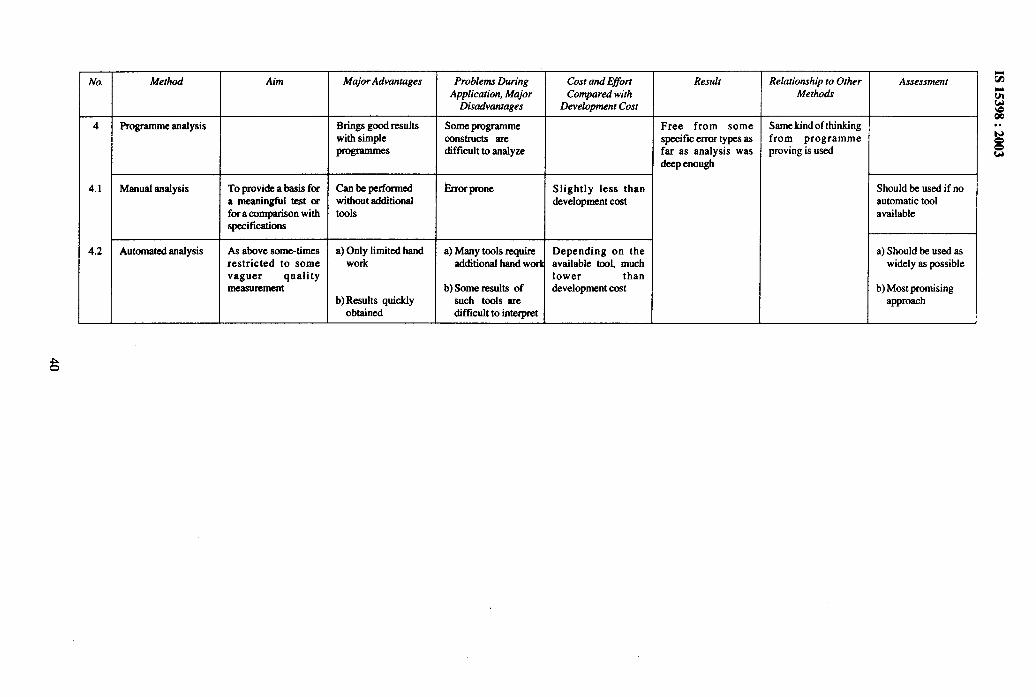
No. Method Aim MajorAdvantages Problems During Cost ondEffort Result Relationship to Other AssessmentApplic&”on, Major Compared with Methoa3
Disadvantages Development Cost
4 Programme malysis Brings good results some programrne Free from some Same kind of thinkingwith simple constructs are specific error types as from programmeprogrammed difficult to arialyze far as analysis was proving is used
deep enough
4.1 Manual analysis To provide a basis for canbeperformed krrorprone Slightly less than Should be used if noa meaningful test or without additional development coat automatic toolfora comparison with tools availablespecifications
4.2 Automated anafysis As above some-times a) Only limited hand a) Many tools require Depending on the a) Should be used asrestricted to some work additional hand work available tool, much wi&ly as possiblevaguer quality lower thanmeasurement b) Some results of development coat b) Moatpromising
b) Results quickly kuch tOOk arE approachobtained Mlcldt to interpret

IS 15398:2003
E-4.2 Systematic Tests
E-4.2.1 General
No. Kind of Test
1
--i-
Cases representative forprogramme behaviour ingeneral, its arithmetic, timing
All individually and explicitlyspecified requirements
II
3 All input variables in extremepositions (crash test)
Z;technical process can sho~with respect to the software
Kind of Detected Errors To be Perj40rrned 1 Remarks )
All, but with no guarantee for Always It is assumed that the systembeing exhaustive works correctly, if the cases are
executed correctly
Forgotten functions detected Always primarily, if required a) Can be an exhaustive test, iicompletely functions are specified in detail funcrkns are@ completely
separate
I b) Does not say much ontiming problems I
Timing errors, but with no Alwaysguarantee. Overflow,underflow
Hardware and software Alwaysinterface design errors
All, but with no guarantee Always Especially valuable, ifsimulator of technical processis available
All, as far as ever relevant If technical process behaviour Only feasible, if processis well known and not too behaviour is simple, cautionmanifold with changes
E-4.2.2 Path Testing
No. Kind of Test Kind of Detected Errors To be Pe~orrned Remarks
1 Every statement executed at Inaccessible code Alwaysleast once
2 Every outcome of every branch Errors in control flow, with no Always Contains 5; can be exhaustive,executed at least once guarantee of completeness if no loops no timing problem
Purely combinatorial problemmapped on programmestructure.
2a Every predicate term exercised Errors in control flow and data lf combhation of tests 8 and 12 Contains 8; included into each branch flow is not applied combination of 8 and 12
2b Each loop executed with Errors in loop control and array Always, if programme containsminimum, maximum and at data handling loopsleast one intermediate numberof repetitions
3 Every path executed at least All the erroneous control flow If combhatorial problem. Only feasible for modulesonce
Contains 8: remember that eacinew loop repetition leads to tnew path
E-4.2.3 Data Movement Testing
No. Kind of Test Kind of Detected Errors To bs Pe~omred Remarks
1 Every assignment to each Errors in data flow, but with no Arrays usedmemory place executed at least guaranteeonce
2 Every reference to each Errors in data flow, exhaustive Arrays used Contains 10 in most casesmemory place executed at least in special casesonce Only reasonable in connection
with 10
3 All mappings from input to All data flow errors Always for individual segments Only feasible for modulesoutput executed at least onceeach Possibly covered by 8,9 or 7
41

IS 15398:2003
E-4.2.4 Timing Testing
No. Kind of Test Kind of Detected Errors To be Pe#ormed Remarks
1 ChecEtngof all time constraints Timing errors, computing time Alwaystoo long
2 Maximum possible Organizational errors If number not too largecombinations of interruptsequences
2a All significant combinations of Organizational errors Alwaysinterrupt sequences
E-4.2.5 Miscellaneous
No. Kind of Test Kind of Detected Errors To be Pesfortned Remarks
1 Check for correct position for Erroneous sub-divisionof input If analogue input is used Number and kind of input dataall boundaries of the input data data space sub-areas to be found byspace analysis
2 Check for sufficient accuracy Numerical errors, errors in If word length of computer isof arithmetical calculations at algorithms, rounding errors short; complicated arithmeticall critical points used
3 Only for programmed: test of Incorrect data transfer between Always Test aid welcomemodule interfaces and module modulesinteraction
3a Every module invoked at least Incorrect control flow and Alwaysonce incorrect data flow between
3b Every invocation to a module- modules, with no guarantee
Alwaysexercised at least once
E-4.3 Statistical Tests
No. Kind of Test Kind of Detected Errors To be Pe~orrned
1 Each input data combination Failure probability-perdemandwith same probability as during p S (2.99/n) withon-line application, n test runs p = 95%
ps (4.6/n) withp = 99%
2 Each input data combhration Failure probability per arbitrarywith equal probability, n runs run, formulae as in row 1 given
above
3 Each programme property Probability of error of an Only reasonable ftested with equal probability, n arbitrary and distinct programme parts nproperties tested prograrnme property, formulae anafysable
as in row 1 given above
4 n runs such that any potentialerror is detected with equalprobabllityp, during one run
-
5 As 3, N programme propertiesn test runs, nNrandom .seIectiorof properties with return
~
Probability to detect an Diftlculty to estimatcp,
Probability to test eachprogramme property at leastonce
n-1
P = 1 + ~ (-1~ (N/J) [(N- l)/NJnj=l
6 n test points randomly Mean distance of two test Useful to test correctnessdistributed in k - dimensional points in direction of an positions of boundariesprogramme input domain
;::W axissub-domains
Remarks
)etailed knowledge oflperationconditions
(nowledge on detailecmogrammestructure in ordc]o ensure equal probability
%obabilityp~ to touch an errmmown in order to ensure equalmobability
n order to ensure equawobability
42
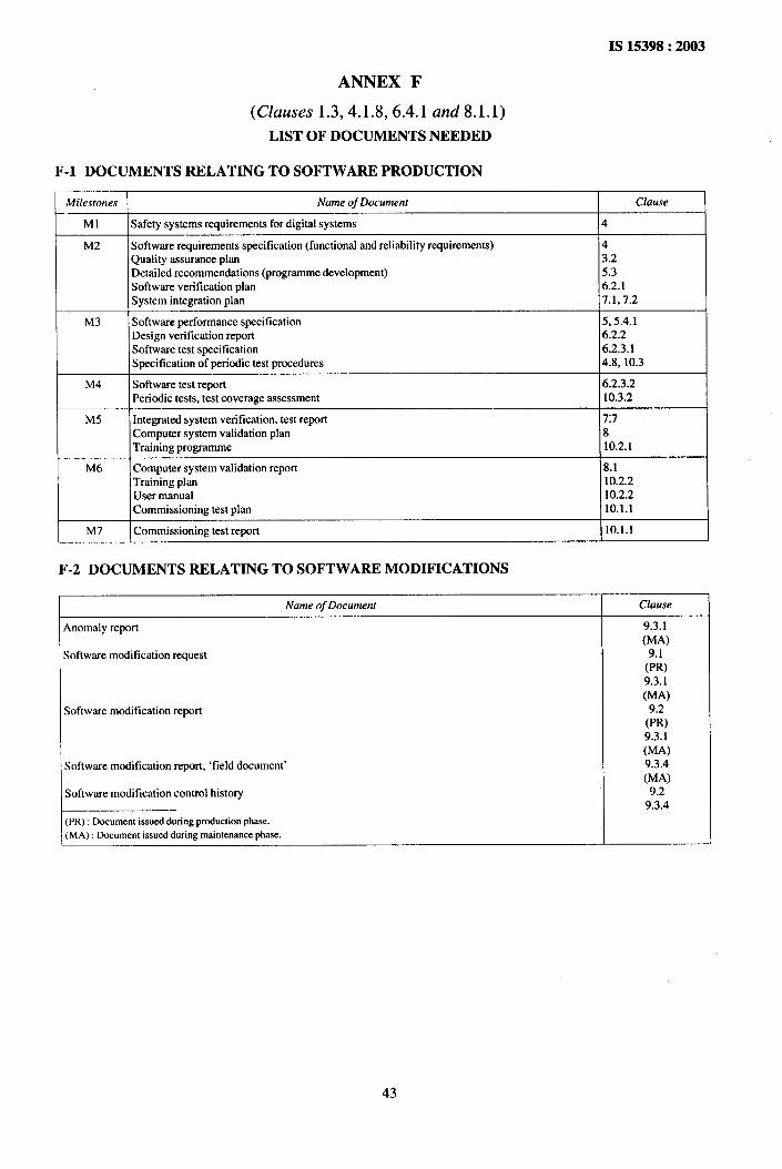
IS 15398:2003
ANNEX F
(Clauses 1.3,4.1 .8,6.4.1 and 8.1.1)
LIST OF DOCUMENTS NEEDED
F-1 DOCUMENTS RELATING TO SOFTWARE PRODUCTION
kfilestones Nameof Document Clause
Ml Safety systems requirements for digital systems 4
M2 Software requirements specification (functional and reliability requirements) 4Quality assurance plan 3.2Detailed recommendations (programme development) 5.3Software verification plan 6.2.1System integration plan 7.1,7.2
M3 Software performance specification 5,5.4.1Design verification report 6.2.2Software test spccitlcation 6.2.3.1Specification of periodic test procedures 4.8, 10.3
M4 Software test repxt 6.2.3.2Periodic tests, test coverage assessment 10.3.2
M5 Integrated system verification, test report 7:7Computer system validation plan 8Training programme 10.2.1
M6 Computer system validation report 8.1Training plan 10.2.2User manual 10.2.2Commissioning test plan 10.1.1
M7 Commissioning test report 10.1.1
F-2 DOCUMENTS RELATING TO SOFTWARE MODIFICATIONS
Name of Document Clause
Anomaly report 9.3.1(MA)
Software modification request(%9.3,1(MA)
Software mrxhtication report(::)9.3.1(MA)
Software modification report, ‘field document’ 9.3.4(MA)
Software modification control history 9.29.3.4
(PR): Documentissuedduringproductionphase.(MA): Documentissuedduringmaintenancephase.
43

F-3 DOCUMENTATION ORGANIZATION RELATING TO THE SOIWWARE REALIZA~ON
F-3.1 Software Generation
Software life cvcldSystem software Software Coding Hardware/Sofhvare Computer System
Requirements Requirements Design Integration Vali&tion
Milestones----* Ma-----------+ M2 ‘---------* M3 -
safety systemsreeommeti]ons
requiremqlts
I —
-------- - * M4 --_---------.--* M5___
softwaresoftware Failure
requhement-b performance + mode
specification analysis. 1
ml
Commissioning I ExploitiMaintenance
--- > M6
--..-----
61Deiivery
I--- M7
I —--l- /’t ! - h-k---l I I Isoftware softwaretest
Sonware
verification specification testreport
plan 1f I 1 r .

F-3.2 System Integration
Sofhvare life cycle$’3tem software Software Coding HardwareKofhvare Computer System Commissioning Exploitl
Requirements Requirements Design Integration Validation Ma@tenance
Milestones----- Mr-----------+ M2 ----------+ M3 ----------- NM‘--------------* M5 ‘-------------b M6
I Delivery
Verification of* failure mode I
analysis )----------+ M7
Integrationsystem
b systemintegrationplan verifmtion
test report
IComputer Computer
system systemvalidationplan validation
I reooft
-LEE=

F-3.3 Modifkation
Software life cyclesoftware Coding Hardware/Sotlware Computersystem Commi*- Exploit/
Design Integration Validation !oning Maintenance
Milestones----+ M~-----------* M:I
Documentation
Related tothesoh’are ~modification
---------- + ~3,.___-* M:.-----------. MS --------------- M:
i I--kG-lL
4)-------P M
1 Production I *
SoftwareI modification ●
request
EEiiiE1’
55Anomaly
report
softwaremodMeation
request
uSofiwaremoMkation
~
softwaremodification
report
+soflwnre
modMcation‘fielddocument’
* /
+
Somvaremodification
controlhistory
. .

IS 15398:2003
ANNEX G
(Foreword)
COMMITTEE COMPOSITION
Nuclear Instrumentation Sectional Committee, LTD 26
OrganizationIndira Gandhi Cerrtre for Atomic Research, Ka!pakkam
Atomic Energy Regulatory Board, Mumbai
Atomic Minerals Division, HyderabadBhabha Atomic ResearchCentre,Mumbai
Centre for AdvancedTechnology,Indore
Electronics Corporation of India Lknited, HyderabadIndian Institute of Technology, Kanpur
Indian Plasma Research Institute, GandhinagarMinistry of Defence (DRDG), New DelhiNuclear Power Corporation, Mumtil
Nuclear Science Centre, New DelhiPLA Electro Appliances Ltd, Mumbai
Saha Institute of NuclearPhysics,Kolkata
Variable Energy Cyclotron Centre, KolkaraBIS Directorate General
Representative(s)SHFUP. SWAMI~ATHAN(Chairman)
SHRIS. A. V. SATHYAMURTHY(Alternate)SHRIP. R. KMSHNAMURTHY
SHRIP. HAJRA(Alternate)SHRtR. SRSEHARIDRS. K. KATARSA
SHRIDEBASHISDAS(Alternate 1)SHtUP. K. MUKHOPADHYAY(Alterrrate 11)
SHRtB. J. VAIDYASHRtA, G. BHUJALE(Alternate)
DRM. S. R. MURTYPROFS. QURESHI
PROFP. MUNSHI(Alternate)DR ANURAGSHYAMSHRIG. C. BHOLASHRIS. RAMAKMSHNAN
SHRIR. Y. Ap@Altet?zate)DR R. K. BHOWMIKSHRtN. R. SHAH
SHRIK. K. M. NAIR(Alternate)DR SUVFWDUBOSE
DR PRATAPBHATrACHARYA(Alternate)SHRIN. K. MUKHOPADHYAYSHRIVUAI, Director &Head (LTD)[Representing Director General (Ex-oflcio)]
Member SecretarySHRIPRAVEENKUMAR
DeputyDirector(LTD),BIS
47

I
Bureau of Indian Standards
BIS is a statutory institution established under the Bureau of Indian Standards Act, 1986 to promoteharmonious development of the activities of standardization, marking and quality certification of goodsand attending to connected matters in the country.
Copyright
BIS has the copyright of all its publications. No part of these publications may be reproduced in any formwithout the prior permission in writing of BIS. This does not preclude the free use, in the course ofimplementing the standard, of necessary details, such as symbols and sizes, type or grade designations.Enquiries relating to copyright be addressed to the Director (Publications), BIS.
Review of Indian Standards
Amendments are issued to standards as the need arises on the basis ‘of comments. Standards are also reviewedperiodically; a standard along with amendments is reaffirmed when such review indicates that no changes areneeded; if the review indicates that changes are needed, it is taken up for revision. Users of Indian Standardsshould ascertain that they are in possession of the latest amendments or edition by referring to the latest issue of‘BIS Catalogue’ and ‘Standards: Monthly Additions’.
. This Indian Standard has been developed from Doc : No. LTD 26 (1974).
Amendments Issued Since Publication
Amend No. Date of Issue Text Affected
BUREAU OF INDIAN STANDARDS
Headquarters :
Manak Bhavan, 9 Bahadur Shah Zafar Marg, New Delhi 110002 Telegrams : Manaksanstha
Telephones :23230131,23233375,2323 9402 (Common to all offices)
Regional Offices : Telephone
Central : Manak Bhavan, 9 Bahadur Shah Zafar Marg
{
23237617NEW DELHI 110002 23233841
Eastern : 1/14 C.I.T. Scheme VII M, V. I. P. Road, Kankurgachi
{
23378499,23378561
KOLKATA 700054 23378626,23379120
Northern : SCO 335-336, Sector 34-A, CHANDIGARH 160022
{
603843609285
Southern : C.I.T. Campus, IV Cross Road, CHENNAI 600113
{
22541216,2254144222542519,22542315
Western : Manakalaya, E9 MIDC, Marol, Andheri (East)
{
28329295,28327858MUMBAI 400093 28327891,28327892
Branches : AHMEDABAD. BANGALORE. BHOPAL. BHUBANESHWAR. COIMBATORE. FARIDABAD.
GHAZIABAD. GUWAHATI. HYDERABAD. JAIPUR. KANPUR. LUCKNOW. NAGPUR.NALAGARH. PATNA. PUNE. RAJKOT. THIRUVANANTHAPURAM. VISAKHAPATNAM,
F’nntedat Prabhat Offset Press, New Delhl-2