IS 12955-2 (1990): Code of practice for in-siitu ...
12
Disclosure to Promote the Right To Information Whereas the Parliament of India has set out to provide a practical regime of right to information for citizens to secure access to information under the control of public authorities, in order to promote transparency and accountability in the working of every public authority, and whereas the attached publication of the Bureau of Indian Standards is of particular interest to the public, particularly disadvantaged communities and those engaged in the pursuit of education and knowledge, the attached public safety standard is made available to promote the timely dissemination of this information in an accurate manner to the public. इंटरनेट मानक “!ान $ एक न’ भारत का +नम-ण” Satyanarayan Gangaram Pitroda “Invent a New India Using Knowledge” “प0रा1 को छोड न’ 5 तरफ” Jawaharlal Nehru “Step Out From the Old to the New” “जान1 का अ+धकार, जी1 का अ+धकार” Mazdoor Kisan Shakti Sangathan “The Right to Information, The Right to Live” “!ान एक ऐसा खजाना > जो कभी च0राया नहB जा सकता ह ै” Bhartṛhari—Nītiśatakam “Knowledge is such a treasure which cannot be stolen” IS 12955-2 (1990): Code of practice for in-siitu determination of rock mass deformability using flexible dilatometer, Part 2: Radial displacement [CED 48: Rock Mechanics]
Transcript of IS 12955-2 (1990): Code of practice for in-siitu ...

Disclosure to Promote the Right To Information
Whereas the Parliament of India has set out to provide a practical regime of right to information for citizens to secure access to information under the control of public authorities, in order to promote transparency and accountability in the working of every public authority, and whereas the attached publication of the Bureau of Indian Standards is of particular interest to the public, particularly disadvantaged communities and those engaged in the pursuit of education and knowledge, the attached public safety standard is made available to promote the timely dissemination of this information in an accurate manner to the public.
इंटरनेट मानक
“!ान $ एक न' भारत का +नम-ण”Satyanarayan Gangaram Pitroda
“Invent a New India Using Knowledge”
“प0रा1 को छोड न' 5 तरफ”Jawaharlal Nehru
“Step Out From the Old to the New”
“जान1 का अ+धकार, जी1 का अ+धकार”Mazdoor Kisan Shakti Sangathan
“The Right to Information, The Right to Live”
“!ान एक ऐसा खजाना > जो कभी च0राया नहB जा सकता है”Bhartṛhari—Nītiśatakam
“Knowledge is such a treasure which cannot be stolen”
“Invent a New India Using Knowledge”
है”ह”ह
IS 12955-2 (1990): Code of practice for in-siitudetermination of rock mass deformability using flexibledilatometer, Part 2: Radial displacement [CED 48: RockMechanics]


Indian Standard
Iiwwru DETERMINATION OF ROCK MASS DEFORMABILITY USING A FLEXIBLE DILATOMETER- CODE OFPRACTICE
‘PART 2 WITH RADIAL DISPLACE-MENT
UDC 6‘24*121.54 : 006.76
@ BIS 1990
BUREAU OF I-NDIAN STANDARDS MANAK BHAVAN, 9 BAHADUR SHAH ZAFAR MARG
NEW DELHI 110002
October 1990 Price Group 3

Rock Mechanics Sectional Committee, CED 48
FOREWORD
This Indian Standard ( Part 2 ) was adopted by the Bureau of Indian Standards on 24 April 1990, after the draft finalized by the Rock Mechanics Sectional Committee had been approved by the Civil Engineering Division Council.
Deformability of rock mass near exposed surface can be determined by many methods such as uniaxial jacking test, radial jacking test, flat test, etc. On the other hand borehole instruments like dilatometers can be used to produce a log of deformability variations with depth. In this they are superior to other methods which are designed only for near-surface application. Dilatometers are particularly valuable for the rapid index logging of drillholes in fragile, clayey or jointed/closely rocks that yield poor core reco- very and inadequate specimens for laboratory testing. The deformability values obtained by dilatometer logging give a very useful record of variations in rock quality and useful comparison of relative defor- mabilities in adjacent rock strata.
The volume of rock stressed by a dilatometer is quite small, usually less than one third of a cubic metre and often too small for direct application of the results to design problems. Correlation of the dilatometer modulus with that obtained, for example, by plate jacking radial jacking, or flat jack methods allows an extrapolation of the dilatometer test results to the large scale. Adjustments are also needed to take into account the fact that a dilatometer test carried out in a vertical hole gives information on horizontal deformability, whereas it is vertical deformability that is often more relevant, ~for example to foundations.
Both the types of dilatometers referred to in this standard are ‘flexible’ in that they apply a uniformly distributed pressure to the drillhole wall through a flexible membrane, and in this, they differ from ‘rigid’ dilatometers such as the goodman jack which has semi-cylindrical loading platens or steel, and, therefore, directional pressure application.
The two methods given here relate to two types of ‘flexible’ dilatometers. The first covered in Part 1 mea- sures the drillhole volume change from which radial displacements must be calculated, whereas the second covered in Part 2 measures the radial displacements directly using displacement transducers. Only the direct measuring type can be used to determine anisotropy of deformability as a function of radial direction within the drillhole, volume change types give an average value for the deformability modulus.
The present standard is limited to describing the measurement of rock mass deformability, which is the principal use of the dilatometer.

IS 12955 ( Part 2 ) : 1990
Indian Standard
IN-NIT-U DETERMINATIONOFROCKMASS DEFORMABILITYUSINGAFLEXIBLE DILATOMETER-CODEOFPRACTICE
PART 2 WITH RADIAL DISPLACEMENT
1 SCOPE
1.1 This standard ( Part 2 ) covers the method for determination of deformation modulus of rock in-situ using an expanding, probe ( dilatometer ) to exert pressure on the walls of a drillhole. The resulting hole expansion ( dilation ) is measured directly by a displacement transducer in the probe. Deforma- bility characteristics of the rock mass at the dilatometer location may be calculated from the relation between pressure dilation. Anisotropy of deformability in the plane perpendicular to the drillhole may also be determined.
2 REFERENCE
2.1 The Indian Standards listed in Annex A are necessary adjuncts to this standard.
3 LOCATION OF TEST SITE
3.1 Drillhole locations and depths -are to be selec- ted taking into account the anticipated rock quality variations and depths of weathering, and the requirements of the designs of which the test data are needed.
3.2 Within each drillhole, the tests may be spaced either at equal intervals or at specified locations in pre-selected geological formations or beds. Generally, a log of deformability should be taken at regular interval along the length of the test hole pertinent to design. For example a 1, 2 or 5 m test interval may be specified depending on test hole lengths and required resolution.
4 PREPARATION OF TEST SITE
4.1 Test holes are to be drilled with the utmost care to preserve their stability, bearing in mind that rock fragments inadvertently wedged between the probe and the drillhole wall can trap the dilatometers permanently. The hole diameter is to be 0.5-3.0 mm larger than the deflated diameter of the probe.
4.2 For checking of the drillhole use of a TV camera may be considered to avoid damage to the flexible membrane that might be caused by open fissures or voids. When the drillhole requires support, this may be achieved by casing down to the uppermost test section and/or by cementing.
4.3 Drill cores are to be fully logged to record core recovery, fracture frequency, rock charac- teristics, weathering and structural features such as schistosity, foliation, bedding and joints. Rock cores are to be available on site for inspection by the testing crew, if necessary.
5 TEST EQUIPMENT
5.1 Equipment for drilling and preparing the test hole.
5.1.1 A drill or boring machine to produce a test hole of the required diameter to the required depth of investigation.
5.1.2 Casing as necessary to support the wall of the hole outside its test sections.
5.1.3 Equipment and materials for grouting and redrilling the test sections within the hole (see 4.2 ).
5.1.4 A diameter gauge ( for example, a cylinder of the same size as the probe ) to check that the hole is clear for insertion of the dilatometer.
5.2 Calibration ~Equipment
5.2.1 A dummy probe of known elastic properties with internal diameter equal to that of the test hole and with length similar to the active length of the probe.
5.2.2 A micrometer gauge to measure the outside diameter of the probe, with an accuracy of $-Cl.02 mm or better.
5.3 The Dilatometer Probe ( Fig. 1 )
5.3.1 A dilatometer probe, which includes a high pressure flexible membrane mounted on a core, such that the membrane can be inflated to press against the drillhole wall. The membrane has to be strong enough to avoid damage when inserted into and withdrawn from the drillhole, yet flexible enough to transmit not less than 90 percent of the applied hydraulic pressure. Typical dilatometer probes have a ~diameter of 76 to 116 mm and effective lengths of 5-15 times their diameter.
5.3.2 A means of inserting, raising and lowering the probe in the hole and of measuring its position to within + 5 cm and its orientation to + 5 degree. Drill rods, special installing rods or cables may be used,
1

IS 12955 ( par* 2 ) : 1980
CONTACT HEAD
All dimensions in millimetres.
FIG. 1 LNEC-TYPE DILATOMBTER
5.4 A Hydraulic System to Pressurize the Probe
5.4.1 A pump and tubing system capable of filling, inflating and deflating the probe and of applying and maintaining the required range of pressures.
5.4.2 The use of electrically operated pump with a pressure controller to maintain loads or apply a constant loading rate, may be preferred.
5.4.3 Testing in a large drillhole using a large diameter probe may require the use of tw o pumps, or a two speed pump with done pumping rate for filling the system and applying initial pressure, and another for pressurization.
5.5 Measuring Systems
5.5.1 One or more displacement measuring sys- tems to determining drillhole diameter with an accuracy of + O-02 mm or better. For example, three electrical displacement transducers of LVDT ( linear variable differential transformer ) type may be mounted to measure along diameters inclined at 120 degrees to each other. The transducers are connected by electrical cables to a readout unit at surface.
5.5.2 A pressure measuring system such as Bourdon gauge or an electric pressure transducer, with range as required and with reading sensiti- vity better than + 2 percent of the range to be employed in any one test.
NOTE - For measurements in hard rocks a pressure range of at least 20 MPa is recommended. Pressurizing fluids that have been used include glycerin, ethylene glycol, water or hydraulic oil.
6 TEST PROCEDURES
6.1 Calibration
6.1.1 The complete dilatometer equipment is to be thoroughly checked and calibrated before each test series, also at least weekly during a testing programme and after major repairs such as mem- brane replacement.
6.1.2 With the probe inserted in the calibration cylinder, the full test pressure is to be applied and a check made for pressure maintenance and Ieakage.
6.1.3 Pressure is then to be~released and increased incrementally through the range to be used in actual testing, taking at least five readings of pressure ( MPa ) and corresponding dilation. If the cell contains more than on-e displacement transducer, the readings are to be compared and then averaged, a pressure versus average dilation curve is to be plotted and its slope mm ( MPa per mm ) compared with theoretical cylinder expansion obtained from elastic theory 2.
6.1.4 The probe is to be inflated in air ( without confinement ) to determine the membrane rigidity correction factor m ( NPa/mm ) obtained as the slope of the unconfined pressure dilation curve.
6.1.5 The displacement measuring system should also be independently checked using a micrometer, preferably one spanning directly between the measuring pads of the probe. Within the measure- ment range, the overall sensitivity of the equip- ment should be constant, for example, one dial division of the readout voltmeter per millimeter of dilation.
6.2 Testing
6.2.1 Having checked clearance of the hole using the diameter gauge, the probe’ is to be inserted and lowered or raised to the required test loca- tion. This location is to be measured with an accuracy of + 5 cm and recorded.
6.2.2 The probe is to be expanded under a pres- sure just enough to ensure permanent contact with no sliding. This seating pressure is to be the minimum pressure throughout the test.
6.2.3 Pressure is to be increased in not less than five approximately equal increments to the maxi- mum value, which is to be as high as possible but not greater than the safe operating pressure of the test equipment, taking into consideration the smoothness and diameter of the drillhole at !he test depth.
6.2.4 Each pressure increment is to be maintairrd constant while taking readings of pressure ( MPL~ ) and corresponding hole dilation ( mm ). If the probe contains more than one displacement trans- ducer, individual diameter readings are to be
2
recorded in order to compute modulus values as a function of direction. Dilation ( if any ) is to be recorded versus time to give an indication of whether the rock behaviour is tin.e-dependent. Alternatively, the same can be achieved by main- taining the diameter of the probe constant and recording the drop in pressure with time.
6.2.5 At the maximum test pressure, the applied pressure is to be maintained constant during at least 10 minutes, longer if specified. Readings of dilation versus time at constant pressure are again to be tabulated to determine creep rates,
6.2.6 Dilation and pressure readings may then be taken during unloading if specified. Three cycles of loading and unloading are required in most applications.
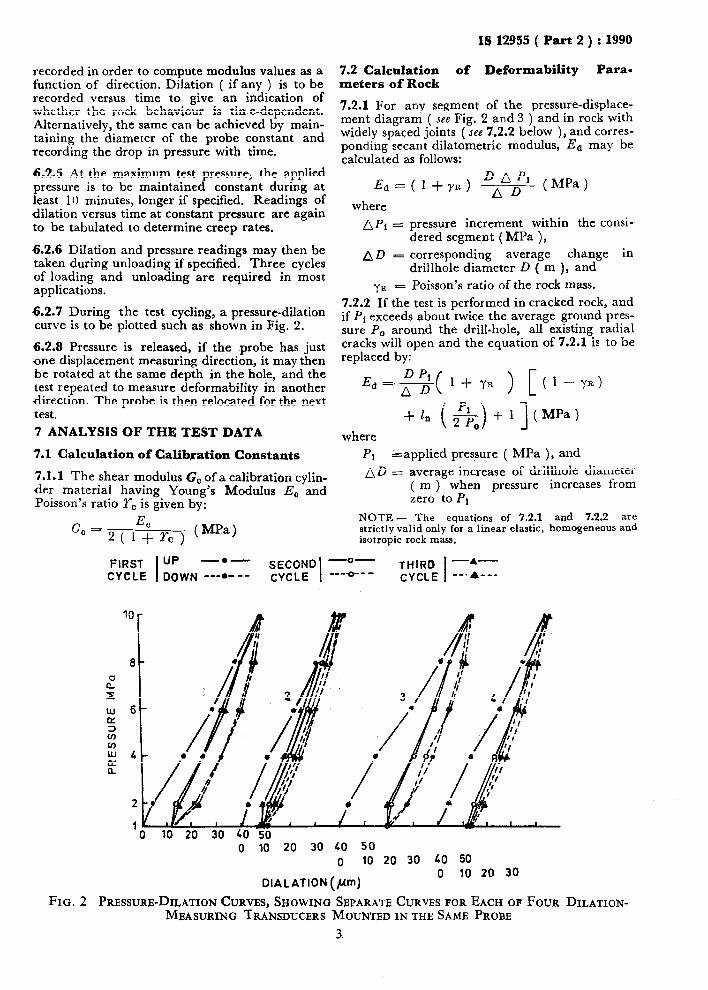
6.2.7 During the test cycling, a pressure-dilation curve is to be plotted such as shown in Fig. 2.
6.2.8 Pressure is released, if the probe has just one displacement measuring -direction, it may then be rotated at the same depth in the hole, and the test repeated to measure deformability in another direction. The probe is then relocated for the next test.
7 ANALYSIS OF THE TEST DATA
7.1 Calculation of Calibration Constants
7.1 l 1 The shear modulus G, of a calibration cylin- der material having Young’s ModuIus E, and Poisson’s ratio r, is given by:
EC Gc=q l+yc) (MPa)
IS 12955 ( Part 2 ) : 1990
7.2 Calculation of Deformability Para- meters of Rock
7.2.1 For any segment of the pressure-displace- ment diagram ( see Fig. 2 and 3 ) and in rock with widely spaced joints ( see 7.2.2 below ), and corres- ponding secant dilatometric modulus, Ed may be calculated as follows:
Ed = ( 1 + ~1% ) DL’p’ ( MPa )
where
nri = pressure increment within the consi- dered segment ( MPa ),
AD = corresponding average change in drillhole diameter D ( m ), and
YR = Poisson’s ratio of the rock mass. 7.2.2 If the test is performed in cracked rock, and if Pi exceeds about twice the average ground pres- sure P, around the drill-hole, all existing radial cracks will open and the equation of 7.2.1. is to be replaced by:
Ed=s( l+yR ) [(l-ye) +I, ~&-e +l (MPa)
) 1 where
Pi &applied pressure ( MPa ), and AD = average increase of drillhole diameter
( m ) when pressure increases from zero to Pi
NOTE - The equations of 7.2.1 and 7.2.2 are strictly valid only for a linear elastic, homogeneous and isotropic rock mass.
FIRST up I
-.- SECOND -o- THIRD -*- CYCLE DOWN ---.--- I CYCLE ---‘O--- I CYCLE --.A---
DIALATION (pm)
FIG. 2 PRESSURE-DILATION CURVES, SHOWING SBPARATB CURVES FOR EACH OF FOUR DILATION- MBASURING TRANSDUCBRS MOUNTED IN THE SAME PROBE
3

IS 12955 ( Part 2 ) : 1990
SCALE FOR DILATION (Xl&-n)
0200
FIG. 3 DILATIONS OF DRILLHOLE WALL, MEASURED BY DILATOMETBR WITH THRBE
DISPLACBMENTS TRANSDUCBRS, AT PRBSSURES OF 1, 2, 5, 10, 20 AND 40 MPa
7.2.3 When the cell contains several diametral displacement transducers or when a single trans- ducer cell has been rotated to measure anisotropy of deformability, the measured dilations for several directions of measurement are to be plot- ted as shown in Fig. 3. Deformability values are then to be calculated for each direction of measurement.
8 REPORTING OF RESULTS
8.1 The following are to be reported for the site as a whole:
4
b)
cl
4
4
Details of drilling including drilling agency, method and equipment used. A map of drillhole locations and a tabula- tion of hole lengths, diameters, inclinations and directions.
Geotechnical logs of the drill core, showing locations of cased and cemented sections, if any, groundwater levels, rock types and characteristics, locations of test sections. Characteristics of all discontinuities within each test section and 0.5 m above and below [ seeIS 11315 ( Parts 1 to 11 j 1.
Details of the method and equipment for calibration and testing, stating departures from the procedures given in this standard.
f) Full results of calibration.
8.2 The following are to be reported for each test:
a)
b)
c)
7.2.4 From the pressure-dilation diagram, both short-term and time dependent response of the rock mass can be determined.
d)
Tabulated test readings, including both raw and corrected values with depths and directions of measurement and graphs as in Fig. 2. Derived values of deformability parameters, together with details of methods land assumptions used in their derivation. Defor- mability parameters should be tabulated and shown graphically as a function of applied pressure. Logs of deformability variation as a func- tion of depth ( or distance from the drill- hole collar in case of a non-vertical hole ). Graphs in the plane perpendicular to the drillhole, showing anisotropy of the measu- red dilations and deformability values.
IS No.
11315 ( Part 1 ) : 1987
11315 ( Part 2 ) : 1987
11315 ( Part 3 ) : 1987
11315 ( Part 4 ) : 1987
ANNEX A
( Clause 2.1 )
LIST OF REFERRED INDIAN STANDARDS
Title
Method for the quantitative description of discontinuities in rock mass: Part 1 Orientation
Method for the quantitative description of discontinuities in rock mass: Part 2 Spacing
Method for the quantitative description of discontinuities in rock mass: Part 3 Persistence
Method for the quantitative description of discontinuities in rock mass: Part 4 Roughness
4

IS 30.
11315 ( Part 5 ) : 1987
11315 ( Part 6 ) : 1
11315(Part7):
987
987
11315 ( Part 8 ) : 1 987
11315 ( Part 9 ) : 1987
11315 ( Part 10 ) : 1987
11315 ( Part 11 ) : 1985
IS 12955 ( Part 2 ) : -1990
Title
Method for the quantitative description of discontinuities in rock mass: Part 5 Wall strength
Method for the quantitative description of discontinuities in rock mass: Part 6 Aperture
Method for the quantitative description of discontinuities in rock mass: Part 7 Filling
Method for the quantitative description of discontinuities in rock mass: Part 8 Seepage
Method for the quantitative description of discontinuities in rock mass: Part 9 Number of sets
Method for the quantitative description of discontinuities in rock mass: Part 10 Block size
Method for the quantitative description of discontinuities in rock mass: Part 11 Core recovery and rock quality

Standard Mark
The use of the Standard Mark is governed by the provisions of the Bureau of Indian Standards Act, 1986 and the Rules and Regulations made thereunder. The Standard Mark on products covered by an Indian Standard conveys the assurance that they have been produced to comply with the requirements of that standard under a well defined system of inspection, testing and quality control which is devised and supervised by BIS and operated by the producer. Standard marked products are also continuously checked by BIS for conformity to that standard as a further safeguard. Details of conditions under which a licence for the use of the Standard Mark may be granted to manufacturers or producers may be obtained from the Bureau of Indian Standards.

Bureau of Indian Standardr
BIS is a statutory institution established under the Bureau of Indian Standards Act, I986 to harmonious development of the activities of standardization, marking and quality certification and attending to connected matters in the country.
Copyright
promote of goods
BIS has the copyright of all its publications. No part of these publications may be reproduced in any form without the prior permission in writing of BIS. This does not preclude the free use, in the course of implementing the standard, of necessary details, such as symbols and sizes, type or grade designations, Enquiries relating to copyright be addressed to the Director ( Publications ), BIS.
Revision of Indian Standards
Indian Standards are reviewed periodically and revised, when necessary and amendments, if any, issued from time to time. Users of Indian Standards should ascertain that they are in possession of latest amendments or edition. Comments on this Indian Standard may be sent to BIS giving following reference:
Dot : No. CED 48 ( 4697 )
Amendments Issued Since Publication
are the the
Amend No. Date of Issue Text Affected
-.
BUREAU OF INDIAN STANDARDS
Headquarters :
Manak Bhavan, 9 Bahadur Shah Zafar Marg, New Delhi 110002 Telegrams : Manaksanstha Telephones : 331 01 31,331 13 75 ( Common to all Offices )
Regional
Central :
Eastern :
offices :
Manak Bhavan, 9 Bahadur Shah Zafar Marg NEW DELHI 110002
1 14 C. JAL
I. T. Scheme VII M, V. I. P. Road, Maniktola CUTTA 700054
Telephone
t 331 01 31 331 13 75
3786 62
Northern : SC0 445-446, Sector 35-C, CHANDIGARH 160036 2 ia 43
Southern : C. I. T. Campus, IV Cross Road, MADRAS 600113 41 29 16
Western : Manakalaya, E9 MIDC, Marol. Andheri ( East ) BOMBAY 400093
Branches : AHMADABAD. BANGALORE. BHOPAL. BHUBANESWAR. COIMBATORE. FARIDABAD. GHAZIABAD. GUWAHATI. HYDERABAD. JAIPUR. KANPUR. PATNA. THIRUVANANTHAPURAM.
6 32 92 95
Printed at New India Printing Prers. Khuris. India