IS 11948 (2010): AUTOMOTIVE VEHICLES — STEERING … · “Step Out From the Old to the New” ......
19
Disclosure to Promote the Right To Information Whereas the Parliament of India has set out to provide a practical regime of right to information for citizens to secure access to information under the control of public authorities, in order to promote transparency and accountability in the working of every public authority, and whereas the attached publication of the Bureau of Indian Standards is of particular interest to the public, particularly disadvantaged communities and those engaged in the pursuit of education and knowledge, the attached public safety standard is made available to promote the timely dissemination of this information in an accurate manner to the public. इंटरनेट मानक “!ान $ एक न’ भारत का +नम-ण” Satyanarayan Gangaram Pitroda “Invent a New India Using Knowledge” “प0रा1 को छोड न’ 5 तरफ” Jawaharlal Nehru “Step Out From the Old to the New” “जान1 का अ+धकार, जी1 का अ+धकार” Mazdoor Kisan Shakti Sangathan “The Right to Information, The Right to Live” “!ान एक ऐसा खजाना > जो कभी च0राया नहB जा सकता ह ै” Bhartṛhari—Nītiśatakam “Knowledge is such a treasure which cannot be stolen” IS 11948 (2010): AUTOMOTIVE VEHICLES — STEERING EFFORT — METHOD OF EVALUATION [TED 4: Automotive Braking Systems]
-
Upload
truongdien -
Category
Documents
-
view
217 -
download
0
Transcript of IS 11948 (2010): AUTOMOTIVE VEHICLES — STEERING … · “Step Out From the Old to the New” ......

Disclosure to Promote the Right To Information
Whereas the Parliament of India has set out to provide a practical regime of right to information for citizens to secure access to information under the control of public authorities, in order to promote transparency and accountability in the working of every public authority, and whereas the attached publication of the Bureau of Indian Standards is of particular interest to the public, particularly disadvantaged communities and those engaged in the pursuit of education and knowledge, the attached public safety standard is made available to promote the timely dissemination of this information in an accurate manner to the public.
इंटरनेट मानक
“!ान $ एक न' भारत का +नम-ण”Satyanarayan Gangaram Pitroda
“Invent a New India Using Knowledge”
“प0रा1 को छोड न' 5 तरफ”Jawaharlal Nehru
“Step Out From the Old to the New”
“जान1 का अ+धकार, जी1 का अ+धकार”Mazdoor Kisan Shakti Sangathan
“The Right to Information, The Right to Live”
“!ान एक ऐसा खजाना > जो कभी च0राया नहB जा सकता है”Bhartṛhari—Nītiśatakam
“Knowledge is such a treasure which cannot be stolen”
“Invent a New India Using Knowledge”
है”ह”ह
IS 11948 (2010): AUTOMOTIVE VEHICLES — STEERING EFFORT —METHOD OF EVALUATION [TED 4: Automotive Braking Systems]


© BIS 2010
B U R E A U O F I N D I A N S T A N D A R D SMANAK BHAVAN, 9 BAHADUR SHAH ZAFAR MARG
NEW DELHI 110002
November 2010 Price Group 7
IS 11948 : 2010
Hkkjrh; ekud
Lopy okgu — LVh;fjax iz;kl — ewY;kadu i)fr¼ nwljk iqujh{k.k ½
Indian Standard
AUTOMOTIVE VEHICLES — STEERINGEFFORT — METHOD OF EVALUATION
( Second Revision )
ICS 43.040.50
Automotive Braking Systems, Vehicle Testing and Performance Evaluation Sectional Committee, TED 4
FOREWORD
This Indian Standard (Second Revision) was adopted by the Bureau of Indian Standards, after the draft finalizedby the Automotive Braking Systems, Vehicle Testing and Performance Evaluation Sectional Committee had beenapproved by the Transport Engineering Division Council.
The overall performance of an automotive vehicle is a function of the performance of its various systems andcomponents. The steering system is one of the main systems that directly contribute to the active safety of thedriver and the other road users.
This standard was first published in 1986 and was first revised in 1999. This revision has been taken up to alignthe standard with ECE Regulation 79 — Revision 2 Amendment 2. This revised standard additionally considersthe following:
a) Provisions for trailers and the trailers with hydraulic steering transmissions.b) Braking performance for vehicles using the same energy source to supply steering equipment and braking
device (see Annex A).c) Additional provisions for vehicles equipped with auxiliary steering equipment.
d) Special requirements to be applied for the safety aspects of complex electronic vehicle control systems.
For the purpose of deciding whether a particular requirement of this standard is complied with, the final value,observed or calculated, expressing the result of a test or analysis, shall be rounded off in accordance with IS 2 : 1960‘Rules for rounding off numerical values (revised)’. The number of significant places retained in the rounded offvalue should be the same as that of the specified value in this standard.
1
IS 11948 : 2010
1 SCOPE
1.1 This standard specifies the method of evaluationof steering efforts of automotive vehicles. This standardapplies to the steering equipment of vehicles ofcategories M, N and O as defined in IS 14272(Part 1) : 1995 ‘Automotive vehicles — Types —Terminology: Part 1 Three and four wheelers’.
1.2 This standard does not apply to,
a) steering equipment with a purely pneumatictransmission;
b) autonomous steering systems as definedin 3.3.3;
c) full power steering systems fitted to trailerswhere the energy necessary for operation istransmitted from the towing vehicle; and
d) the electrical control of full power steeringsystems fitted to trailers, other than additionalsteering equipment as defined in 3.5.2.4.
2 REFERENCES
The following standards contain provisions, whichthrough reference in this text, constitute provisions ofthe standard. At the time of publication, the editionindicated were valid. All standards are subject torevision and parties to agreements based on thisstandard are encouraged to investigate the possibilityof applying the most recent editions of the standardindicated below:
IS No. Title
7079 : 2008 Automotive vehicles — Brake hoseassemblies for hydraulic brakingsystems used with non-petroleumbase brake fluid — Specification(third revision)
14272 Automotive vehicles — Types —(Part 1) : 1995 Terminology: Part 1 Three and four
wheelersISO 2575 : 2004 Road vehicles — Symbols for
controls, indicators and tell-tales
3 DEFINITIONS
For the purposes of this standard the followingdefinitions shall apply.
Indian Standard
AUTOMOTIVE VEHICLES — STEERINGEFFORT — METHOD OF EVALUATION
( Second Revision )
3.1 Approval of a Vehicle, means the approval of avehicle type with regard to its steering equipment.
3.2 Vehicle Type, means the vehicle, which does notdiffer with respect to the manufacturer’s designationof the vehicle type and in essential characteristics,such as type of steering equipment, steering control,steering transmission, steered wheels, and energysource.
3.3 Steering Equipment, means all the equipment thepurpose of which is to determine the direction ofmovement of the vehicle. The steering equipmentconsists of steering control, steering transmission,steered wheels and the energy supply, if any.
3.3.1 Steering Control, means the part of the steeringequipment, which controls its operation, it may beoperated with or without direct intervention of thedriver. For steering equipment in which the steeringforces are provided solely or partly by the musculareffort of the driver the steering control includes allparts up to the point where the steering effort istransformed by mechanical, hydraulic or electricalmeans.
3.3.2 Steering Transmission, means all components,which form a functional link between the steeringcontrol and the road wheels. The transmission isdivided into two independent functions.
The control transmission and the energy transmission.Where the term transmission is used alone in thisstandard, it means both the control transmission andthe energy transmission. A distinction is drawn betweenmechanical, electrical and hydraulic transmissionsystems or combinations thereof, according to themeans by which the signals and/or energy istransmitted.
3.3.2.1 Control transmission, means all componentsby means of which signals are transmitted for controlof the steering equipment.
3.3.2.2 Energy transmission, means all componentsby means of which the energy required for control/Standard of the steering function of the wheels istransmitted.
3.3.3 Autonomous Steering System, means a system
2
IS 11948 : 2010
that incorporates a function within a complex electroniccontrol system that causes the vehicle to follow adefined path or to alter its path in response to signalsinitiated and transmitted from off-board the vehicle.The driver will not necessarily be in primary controlof the vehicle.
3.3.4 Advanced Driver Assistance Steering System,means a system, additional to the main steering system,that provides assistance to the driver in steering thevehicle but in which the driver remains at all times inprimary control of the vehicle. It comprises one or bothof the following functions:
3.3.4.1 Automatically commanded steering function,means the function within a complex electronic controlsystem where actuation of the steering system can resultfrom automatic evaluation of signals initiated on-boardthe vehicle, possibly in conjunction with passiveinfrastructure features, to generate continuous controlaction in order to assist the driver in following aparticular path, in low speed manoeuvring or parkingoperations.
3.3.4.2 Corrective steering function, means thediscontinuous control function within a complexelectronic control system whereby, for a limitedduration, changes to the steering angle of one or morewheels may result from the automatic evaluation ofsignals initiated on-board the vehicle, in order tomaintain the basic desired path of the vehicle or toinfluence the vehicle’s dynamic behaviour. Systemsthat do not themselves positively actuate the steeringsystem but that, possibly in conjunction with passiveinfrastructure features, simply warn the driver of adeviation from the ideal path of the vehicle, or of anunseen hazard, by means of a tactile warningtransmitted through the steering control, are alsoconsidered to be corrective steering.
3.3.5 Steered Wheels, means the wheels the alignmentof which may be altered directly or indirectly in relationto the longitudinal axis of the vehicle in order todetermine the direction of movement of the vehicle.(The steered wheels include the axis around which theyare rotated in order to determine the direction ofmovement of the vehicle.)
3.3.6 Energy Supply, includes those parts of the steeringequipment, which provide it with energy, regulate thatenergy and where appropriate, process and store it. Italso includes any storage reservoirs for the operatingmedium and the return lines, but not the vehicle’sengine or its drive to the energy source.
3.3.6.1 Energy source, means the part of the energysupply, which provides the energy in the required form.
3.3.6.2 Energy reservoir, means that part of the energysupply in which the energy provided by the energy
source is stored, for example, a pressurized fluidreservoir or vehicle battery.
3.3.6.3 Storage reservoir, means that part of theenergy supply in which the operating medium is storedat or near to the atmospheric pressure, for example afluid reservoir.
3.4 Steering Parameters
3.4.1 Steering Control Effort, means the force appliedto the steering control in order to steer the vehicle.
3.4.2 Steering Time, means the period of time fromthe beginning of the movement of the steering controlto the moment at which the steered wheels have reacheda specific steering angle.
3.4.3 Steering Angle, means the angle between theprojection of a longitudinal axis of the vehicle and theline of intersection of the wheel plane (being the centralplane of the wheel, normal to the axis around which itrotates) and the road surface.
3.4.4 Steering Forces, mean all the forces operating inthe steering transmission.
3.4.5 Mean Steering Ratio, means the ratio of theangular displacement of the steering control to themean of the swept steering angle of the steered wheelsfor a full lock-to-lock turn.
3.4.6 Turning Circle, means the circle within whichare located the projections onto the ground plane ofall the points of the vehicle, excluding the externalmirrors and the front direction indicators, when thevehicle is driven in a circle.
3.4.7 Nominal Radius of Steering Control, means inthe case of a steering wheel the shortest dimension fromits centre of rotation to the outer edge of the rim. Inthe case of any other form of control it means thedistance between its centre of rotation and the point atwhich the steering effort is applied. If more than onesuch point is provided, the one requiring the greatesteffort shall be used.
3.5 Types of Steering Equipment
Depending on the way the steering forces are produced,the following types of equipment are distinguished:
3.5.1 For Motor Vehicles
3.5.1.1 Main steering system, means the steeringequipment of a vehicle, which is mainly responsiblefor determining the direction of travel. It maycomprise:
3.5.1.1.1 Manual steering equipment, in which thesteering forces result solely from the muscular effortof the driver.
3
IS 11948 : 2010
3.5.1.1.2 Power assisted steering equipment, in whichthe steering forces result from both the muscular effortof the driver and the energy supply (supplies). Steeringequipment in which the steering forces result solely,from one or more energy supplies when the equipmentis intact, but in which the steering forces can beprovided by the muscular effort of the driver alone ifthere is a fault in the steering (integrated powersystems), is also considered to be power assistedsteering equipment.
3.5.1.1.3 Full-power steering equipment, in which thesteering forces are provided solely by one or moreenergy supplies.
3.5.1.2 Self-tracking steering equipment, means asystem designed to create a change of steering angleon one or more wheels only when acted upon by forcesand/or moments applied through the tyre to roadcontact.
3.5.1.3 Auxiliary steering equipment (ASE), means asystem in which the wheels on axle(s) of vehicles ofCategories M and N are steered in addition to thewheels of the main steering equipment in the same oropposite direction to those of the main steeringequipment and/or the steering angle of the front and/orthe rear wheels may be adjusted relative to vehiclebehaviour.
3.5.2 For Trailers
3.5.2.1 Self-tracking steering equipment, means asystem designed to create a change of steering angleon one or more wheels only when acted upon by forcesand/or moments applied through the tyre to roadcontact.
3.5.2.2 Articulated steering, means equipment in whichthe steering forces are produced by a change indirection of the towing vehicle and in which themovement of the steered trailer wheels is firmly linkedto the relative angle between the longitudinal axis ofthe towing vehicle and that of the trailer.
3.5.2.3 Self-steering, means equipment in which thesteering forces are produced by a change in directionof the towing vehicle and in which the movement ofthe steered trailer wheels is firmly linked to the relativeangle between the longitudinal axis of the trailer frameor a load replacing it and the longitudinal axis of thesub-frame to which the axle(s) is (are) attached.
3.5.2.4 Additional steering equipment, means a system,independent of the main steering system, by which thesteering angle of one or more axle(s) of the steeringsystem can be influenced selectively for manoeuvringpurposes.
3.5.3 Steering Equipment
Depending on the arrangement of the steered wheels,the following types of steering equipment aredistinguished:
3.5.3.1 Front-wheel steering equipment, in which onlythe wheels of the front axle(s) are steered. This includesall wheels which are steered in the same direction.
3.5.3.2 Rear-wheel steering equipment, in which onlythe wheels of the rear axle(s) are steered. This includesall wheels which are steered in the same direction.
3.5.3.3 Multi-wheel steering equipment, in which thewheels of one or more of each of the front and the rearaxle(s) are steered.
3.5.3.3.1 All-wheel steering equipment, in which allthe wheels are steered.
3.5.3.3.2 Buckle steering equipment, in which themovement of chassis parts relative to each other isdirectly produced by the steering forces.
3.6 Types of Steering Transmission
Depending on the way the steering forces aretransmitted, the following types of steeringtransmission are distinguished:
3.6.1 Purely Mechanical Steering Transmission, meansa steering transmission in which the steering forcesare transmitted entirely by mechanical means.
3.6.2 Purely Hydraulic Steering Transmission, meansa steering transmission in which the steering forces,somewhere in the transmission, are transmitted onlyby hydraulic means.
3.6.3 Purely Electric Steering Transmission, means asteering transmission in which the steering forces,somewhere in the transmission, are transmitted onlythrough electric means.
3.6.4 Hybrid Steering Transmission, means a steeringtransmission in which part of the steering forces aretransmitted through one and the other part throughanother of the above mentioned means. However, inthe case where any mechanical part of the transmissionis designed only to give position feedback and is tooweak to transmit the total sum of the steering forces,this system shall be considered to be purely hydraulicor purely electric steering transmission.
3.7 Electric Control Line
Means the electrical connection which provides thesteering control function to the trailer. It comprises theelectrical wiring and connector and includes the partsfor data communication and the electrical energysupply for the trailer control transmission.
4
IS 11948 : 2010
4 CONSTRUCTION PROVISIONS
4.1 General Provisions
4.1.1 The steering equipment shall ensure easy and safehandling of the vehicle up to its maximum design speedor in case of a trailer up to its technically permittedmaximum speed. There must be a tendency to self-centre when tested in accordance with 5.2 with theintact steering equipment. The vehicle shall meet therequirements of 5.2 in the case of motor vehicles andof 5.3 in the case of trailers. If a vehicle is fitted withan auxiliary steering system (ASE), it shall also meetthe requirements of Annex B. Trailers equipped withhydraulic steering transmissions shall also comply withAnnex C.
4.1.2 It must be possible to travel along a straightsection of road without unusual steering correctionby the driver and without unusual vibration in thesteering system at the maximum design speed of thevehicle.
4.1.3 The direction of operation of the steering controlshall correspond to the intended change of directionof the vehicle and there shall be a continuousrelationship between the steering control deflection andthe steering angle. These requirements do not apply tosystems that incorporate an automatically commandedor corrective steering function, or to auxiliary steeringequipment. These requirements may also notnecessarily apply in the case of full power steeringwhen the vehicle is stationary and when the system isnot energized.
4.1.4 The steering equipment shall be designed,constructed and fitted in such a way it is capable ofwithstanding the stresses arising during normaloperation of the vehicle, or combination of vehicles.The maximum steering angle shall not be limited byany part of the steering transmission unless specificallydesigned for this purpose. Unless otherwise specified,it will be assumed that for the purpose of this standard,not more than one failure can occur in the steeringequipment at any one time and two axles on one bogieshall be considered as one axle.
4.1.5 The effectiveness of the steering equipment,including the electrical control lines, shall not beadversely affected by magnetic or electric fields.
4.1.6 Advanced driver assistance steering systems shallonly be approved in accordance with this standardwhere the function does not cause any deterioration inthe performance of the basic steering system. Inaddition they shall be designed such that the drivermay, at any time and by deliberate action, override thefunction.
4.1.6.1 Whenever the automatically commandedsteering function becomes operational, this shall beindicated to the driver and the control action shall beautomatically disabled if the vehicle speed exceeds theset limit of 10 km/h by more than 20 percent or thesignals to be evaluated are no longer being received.Any termination of control shall produce a short butdistinctive driver warning by a visual signal and eitheran acoustic signal or by imposing a tactile warningsignal on the steering control.
4.1.7 Steering Transmission
4.1.7.1 Adjustment devices for steering geometry mustbe such that after adjustment a positive connection canbe established between the adjustable components byappropriate locking devices.
4.1.7.2 Steering transmission, which can bedisconnected to cover different configurations of avehicle (for example on extendable semi-trailers), musthave locking devices, which ensure positive relocationof components; where locking is automatic, there mustbe an additional safety lock which is operatedmanually.
4.1.8 Steered Wheels
The steered wheels shall not be solely the rear wheels.This requirement does not apply to semi-trailers.
4.1.9 Energy Supply
The same energy supply may be used for the steeringequipment and other systems. However in the case ofa failure in any system which shares the same energysupply steering shall be ensured in accordance withthe relevant failure conditions of 4.3.
4.1.10 Control Systems
The requirements of Annex D shall be applied to thesafety aspects of electronic vehicle control systems thatprovide or form part of the control transmission of thesteering function including advanced driver assistancesteering systems. However, systems or functions, thatuse the steering system as the means of achieving ahigher level objective, are subject to Annex D onlyinsofar as they have a direct effect on the steeringsystem. If such systems are provided, they shall not bedeactivated during type approval testing of the steeringsystem.
4.2 Special Provisions for Trailers
4.2.1 Trailers (with the exception of semi-trailers andcentre-axle trailers) which have more than one axlewith steered wheels and semi-trailers and centre-axletrailers which have at least one axle with steered wheelsmust fulfil the conditions given in 5.3. However, fortrailers with self-tracking steering equipment a test
5
IS 11948 : 2010
under 5.3 is not necessary if the axle load ratio betweenthe un-steered and the self-tracking axles equals orexceeds 1.6 under all loading conditions. However fortrailers with self-tracking steering equipment, the axleload ratio between un-steered or articulated steeredaxles and friction-steered axles shall be at least 1 underall loading conditions.
4.2.2 If the towing vehicle of a vehicle combination isdriving straight ahead, the trailer and towing vehiclemust remain aligned. If alignment is not retainedautomatically, the trailer must be equipped with asuitable adjustment facility for maintenance.
4.3 Failure Provisions and Performance
4.3.1 General
4.3.1.1 For the purposes of this standard, the steeredwheels, the steering control and all mechanical partsof the steering transmission shall not be regarded asliable to breakage if they are amply dimensioned, arereadily accessible for maintenance, and exhibit safetyfeatures at least equal to those prescribed for otheressential components (such as the braking system) ofthe vehicle. Where the failure of any such part wouldbe likely to result in loss of control of the vehicle, thatpart must be made of metal or of a material withequivalent characteristics and must not be subject tosignificant distortion in normal operation of the steeringsystem.
4.3.1.2 The requirements of 4.1.2, 4.1.3 and 5.2.1 shallalso be satisfied with a failure in the steering equipmentas long as the vehicle can be driven with the speedsrequired in the respective clauses. In this case 4.1.3shall not apply for full power steering systems whenthe vehicle is stationary.
4.3.1.3 Any failure in a transmission other than purelymechanical must clearly be brought to the attention ofthe vehicle driver as given in 4.4.
4.3.1.4 In the case where the braking system of thevehicle shares the same energy source as the steeringsystem and this energy source fails, the steering systemshall have priority and shall be capable of meeting therequirements of 4.3.2 and 4.3.3 as applicable. Inaddition the braking performance on the firstsubsequent application shall not drop below theprescribed service brake performance, as given inAnnex A.
4.3.1.5 In the case where the braking system of thevehicle shares the same energy supply as the steeringsystem and there is a failure in the energy supply, thesteering system shall have priority and shall be capableof meeting the requirements of 4.3.2 and 4.3.3 asapplicable. In addition the braking performance on the
first subsequent application shall comply with therequirements of A-3.
4.3.1.6 In the case of trailers the requirements of 4.2.2and 5.3.4.1 shall also be met when there is a failure inthe steering system.
4.3.2 Power Assisted Steering Systems
4.3.2.1 Should the engine stop or a part of thetransmission fail, with the exception of those partslisted in 4.3.1.1. there shall be no immediate changesin steering angle. As long as the vehicle is capable ofbeing driven at a speed greater than 10 km/h therequirements given in 5, relating to a system with afailure, shall be met.
4.3.3 Full Power Steering Systems
4.3.3.1 The system shall be designed such that thevehicle cannot be driven indefinitely at speeds above 10km/h where there is any fault which requires operationof the warning signal referred to in 4.4.2.1.
4.3.3.2 In case of a failure within the controltransmission, with the exception of those parts listedin 4.1.4, it shall still be possible to steer with theperformance laid down in 7 for the intact steeringsystem.
4.3.3.3 In the event of a failure of the energy source ofthe control transmission, it shall be possible to carryout at least 24 ‘figure of eight’ manoeuvres, where eachloop of the figure is 40 m diameter at 10 km/h speedand at the performance level given for an intact systemin 5. The test manoeuvres shall begin at an energystorage level given in 4.3.3.5.
4.3.3.4 In the event of a failure within the energytransmission, with the exception of those parts listedin 4.3.1.1, there shall not be any immediate changesin steering angle. As long as the vehicle is capable ofbeing driven at a speed greater than 10 km/h therequirements of 5 for the system with a failure shallbe met after the completion of at least 25 ‘figure ofeight’ manoeuvres at 10 km/h minimum speed, whereeach loop of the figure is 40 m diameter. The testmanoeuvres shall begin at an energy storage levelgiven in 4.3.3.5.
4.3.3.5 The energy level to be used for the tests referredto in 4.3.3.3 and 4.3.3.4 shall be the energy storagelevel at which a failure is indicated to the driver. In thecase of electrically powered systems subject toAnnex D, this level shall be the worst case situationoutlined by the manufacturer in the documentationsubmitted in connection with Annex D and shall takeinto account the effects of, for example temperatureand ageing on battery performance.
6
IS 11948 : 2010
4.4 Warning Signals
4.4.1 General Provisions
4.4.1.1 Any fault which impairs the steering functionand is not mechanical in nature must be signaled clearlyto the driver of the vehicle. Despite the requirementsof 4.1.2 the deliberate application of vibration in thesteering system may be used as an additional indicationof a fault condition in this system.
In the case of a motor vehicle, an increase in steeringforce is considered to be a warning indication; in thecase of a trailer, a mechanical indicator is permitted.
4.4.1.2 If the same energy source is used to supply thesteering system and other systems, an acoustic or opticalwarning shall be given to the driver, when the storedenergy/fluid in the energy/storage reservoir drops to alevel liable to cause an increase in steering effort. Thiswarning may be combined with a device provided towarn of brake failure if the brake system uses the sameenergy source. The satisfactory condition of the warningdevice must be easily verifiable by the driver.
4.4.2 Special Provisions for Full-Power SteeringEquipment
4.4.2.1 Power-driven vehicles shall be capable ofproviding steering failure and defect warning signals,as follows:
a) A red warning signal, indicating failuresdefined in 4.3.1.3 within the main steeringequipment.
b) Where applicable, a yellow warning signalindicating an electrically detected defectwithin the steering equipment, which is notindicated by the red warning signal.
c) If a symbol is used, it must comply withSymbol J 04, ISO/IEC registration number7000-2441 as defined in ISO 2575.
d) The warning signal(s) mentioned above shalllight up when the electrical equipment of thevehicle (and the steering system) is energized.With the vehicle stationary, the steeringsystem shall verify that none of the specifiedfailures or defects is present beforeextinguishing the signal. Specified failures ordefects which should activate the warningsignal mentioned above, but which are notdetected under static conditions, shall bestored upon detection and be displayed atstart-up and at all times when the ignition(start) switch is in the ‘on’ (run) position, aslong as the failure persists.
4.4.3 In the case where additional steering equipmentis in operation and/or where the steering angle
generated by that equipment has not been returned tonormal driving position a warning signal must be givento the driver.
5 TEST PROVISIONS
5.1 General Provisions
5.1.1 The test shall be conducted on a level surfaceaffording good adhesion.
5.1.2 During the test(s) the vehicle shall be loaded toits technically permissible maximum mass and itstechnically permissible maximum load on the steeredaxle(s).
In the case of axles fitted with auxiliary steeringequipment (ASE), this test shall be repeated with thevehicle loaded to its technically permissible maximummass and the axle equipped with ASE loaded to itsmaximum permissible load.
5.1.3 Before the test begins, the tyre pressures shall beas prescribed by the manufacturer for the massspecified in 5.1.2 when the vehicle is stationary.
5.1.4 In the case of any systems that use electricalenergy for part or all of the energy supply, allperformance tests shall be carried out under conditionsof actual or simulated electrical load of all essentialsystems or systems components, which share the sameenergy supply. Essential systems shall comprise at leastlighting systems, windscreen wipers, enginemanagement and braking systems.
5.2 Provisions for Motor Vehicles
5.2.1 It must be possible to leave a curve with a radiusof 50 m at a tangent without unusual vibration in thesteering equipment at the following speed:
Category M1 vehicles: 50 km/h Category M2, M3, N1,N2 and N3 vehicles: 40 km/h or the maximum designspeed if this is below the speeds given above.
5.2.2 When the vehicle is driven in a circle with itssteered wheels at approximately half lock and at aconstant speed of at least 10 km/h, the turning circlemust remain the same or become larger if the steeringcontrol is released.
5.2.3 During the measurement of the control effort,forces with duration of less than 0.2 s shall not be takeninto account.
5.2.4 Measurement of Steering Efforts on MotorVehicles with Intact Steering Equipment
5.2.4.1 The vehicle shall be driven from straight aheadinto a spiral at a speed of 10 km/h. The steering effortshall be measured at the nominal radius of the steeringcontrol until the position of the steering control
7
IS 11948 : 2010
corresponds to turning radius given in the table belowfor the particular category of vehicle with intactsteering. One steering movement shall be made to theright and one to the left.
5.2.4.2 The maximum permitted steering time and themaximum permitted steering control effort with intactsteering equipment are given in the table below foreach category of vehicle.
5.2.5 Measurement of Steering Efforts on MotorVehicles with a Failure in the Steering Equipment
5.2.5.1 The test described in 5.2.4 shall be repeatedwith a failure in the steering equipment. The steeringeffort shall be measured until the position of thesteering control corresponds to the turning radius givenin the table below for the particular category of vehiclewith a failure in the steering equipment.
5.2.5.2 The maximum permitted steering time and themaximum permitted steering control effort with afailure in the steering equipment are given in theTable 1 for each category of vehicle.
5.3 Provisions for Trailers
5.3.1 The trailer must travel without excessive deviationor unusual vibration in its steering equipment whenthe towing vehicle is travelling in a straight line on aflat and horizontal road at a speed of 80 km/h or thetechnically permissible maximum speed indicated bythe trailer manufacturer if this is less than 80 km/h.
5.3.2 With the towing vehicle and trailer having adopteda steady state turn corresponding to a turning circleradius of 25 m (see 3.4.6) at a constant speed of 5 km/h,the circle described by the rearmost outer edge of thetrailer shall be measured. This manoeuvre shall berepeated under the same conditions but at a speed of25 ± 1 km/h. During these manoeuvres, the rearmostouter edge of the trailer travelling at a speedof 25 ± 1 km/h shall not move outside the circle describedat a constant speed of 5 km/h by more than 0.7 m.
5.3.3 No part of the trailer must move more than 0.5 mbeyond the tangent to a circle with a radius of 25 mwhen towed by a vehicle leaving the circular pathdescribed in 5.3.2 along the tangent and travelling at aspeed of 25 km/h. This requirement must be met fromthe point the tangent meets the circle to a point 40 malong the tangent. After that point the trailer must fulfillthe condition specified in 5.3.1.
5.3.4 The annular ground area swept by the towingvehicle/trailer combination with an intact steeringsystem, driving at no more than 5 km/h in a constantradius circle with the front outer corner of the towingvehicle describing a radius of 0.67 × vehicle combinationlength but not less than 12.5 m is to be measured.
5.3.4.1 If, with a fault in the steering system, themeasured swept annular width is greater than 8.3 m,then this shall not be an increase of more than15 percent compared with the corresponding valuemeasured with the intact steering system. There shallnot be any increase in the outer radius of the sweptannular width.
5.3.5 The tests described in 5.3.2, 5.3.3 and 5.3.4 shallbe conducted in both clockwise and anti-clockwisedirections.
6 VEHICLE CHARACTERISTICS
Vehicle characteristics declared by the vehiclemanufacturer to the testing agency shall contain at leastthe details given in Annex E.
NOTE — If the vehicle, submitted for type approval of thevehicle contain details given in Annex A, it is not necessary tosubmit them again.
7 CHANGES IN VEHICLE CHARACTERISTICS
7.1 In case the test is conducted for verification ofcompliance to statutory requirements the followingshall be carried out.
7.2 Every modification to vehicle characteristics
Table 1 Steering Control Effort Requirements(Clause 5.2.5.2)
Intact
With a Failure
Sl No.
Vehicle Category
Maximum Effort daN
Time s
Turning Radius m
Maximum Effort daN
Time s
Turning Radius m
(1) (2) (3) (4) (5) (6) (7) (8)
i) ii)
iii)
M1 M2 M3
15 15 20
4 4 4
12 12 121)
30 30 452)
4 4 6
20 20 20
iv) v)
vi)
N1 N2 N3
20 25 20
4 4 4
12 12 121)
30 40 452)
4 4 6
20 20 20
1) Or full lock, if 12 m radius is not attainable.2) 50 for rigid vehicles with 2 or more steered axles excluding self-tracking equipment.
8
IS 11948 : 2010
declared in accordance with 6 shall be intimated bythe manufacturer to the testing agency.
The testing agency may then consider, whether,
a) the model with changes specifications stillcomplies with the requirements of thisstandard, or
b) any further verification is required to establishcompliance to this standard.
7.3 Changes where testing is considered necessary forestablishing compliance to this standard are as follows:
a) Any increase of weight on steered axle inexcess of 10 percent in case of M1 and N1
type of vehicles and 5 percent for othervehicles.
b) Any increase in wheel base in excess of10 percent incase of M1 and N1 type ofvehicles and 5 percent for other vehicles.
c) Any decrease in steering wheel diameter[see 7.3 (a)].
d) Any change in steering linkage/steering gearbox ratio which decreases the number of turnsof steering wheel from lock to lock.
e) Type of construction of steering gear box(such as re-circulating ball type to rack andpinion type, power steering, etc).
f) An increase of caster angle.g) Increase of tyre size.
h) Change of tyre type from diagonal or crossply to radial ply.
j) Any change in wheel lock angle that affectsthe test turning circle.
k) Increase in number of axles.
m) If steered axle becomes driven:1) In the case of decrease in the steering
wheel diameter, if the effort calculatedfrom the previous test using the newsteering wheel diameter is within limits,are re-test need not be carried out.
2) Change other than those listed above, areconsidered to be having no adverse effecton steering effort.
3) In 7.2 (a) or after results of furtherverification as per 7.2 (b) are successful,the test results shall be validated for thechanges carried out.
ANNEX A
(Foreword and Clause 4.3.1.4)
BRAKING PERFORMANCE FOR VEHICLES USING THE SAME ENERGY SOURCETO SUPPLY STEERING EQUIPMENT AND BRAKING DEVICE
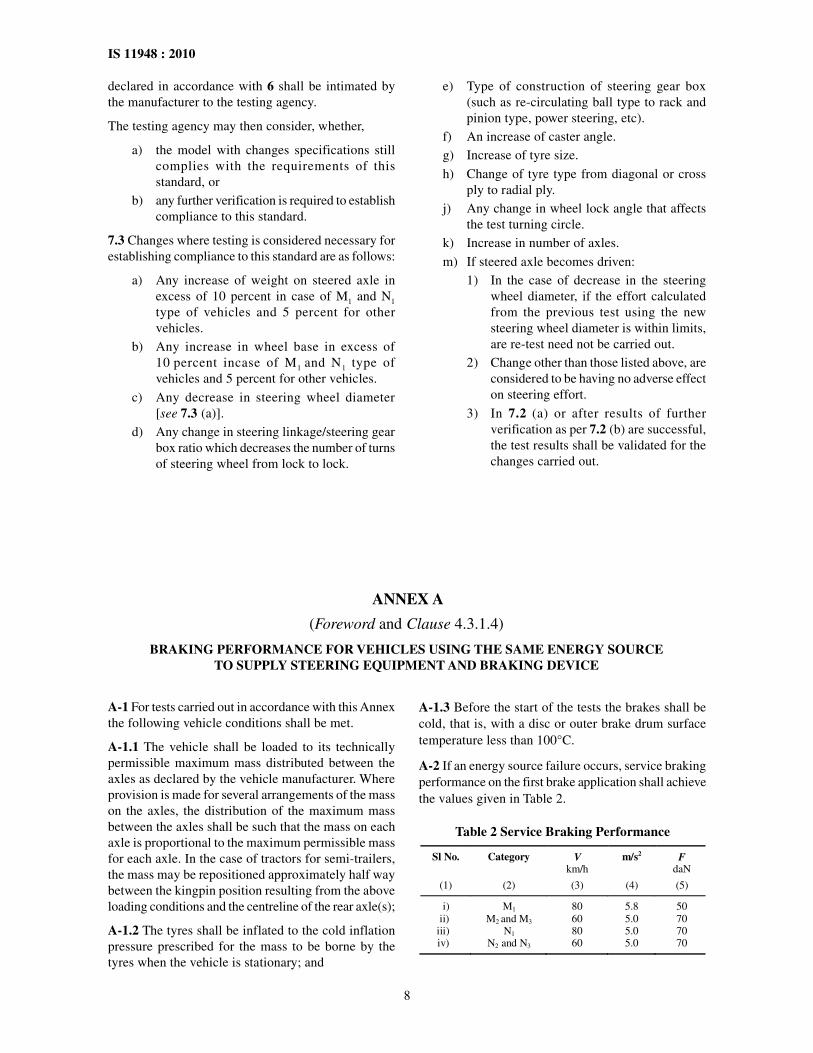
A-1 For tests carried out in accordance with this Annexthe following vehicle conditions shall be met.
A-1.1 The vehicle shall be loaded to its technicallypermissible maximum mass distributed between theaxles as declared by the vehicle manufacturer. Whereprovision is made for several arrangements of the masson the axles, the distribution of the maximum massbetween the axles shall be such that the mass on eachaxle is proportional to the maximum permissible massfor each axle. In the case of tractors for semi-trailers,the mass may be repositioned approximately half waybetween the kingpin position resulting from the aboveloading conditions and the centreline of the rear axle(s);
A-1.2 The tyres shall be inflated to the cold inflationpressure prescribed for the mass to be borne by thetyres when the vehicle is stationary; and
A-1.3 Before the start of the tests the brakes shall becold, that is, with a disc or outer brake drum surfacetemperature less than 100°C.
A-2 If an energy source failure occurs, service brakingperformance on the first brake application shall achievethe values given in Table 2.
Table 2 Service Braking Performance
Sl No. Category V km/h
m/s2 F daN
(1) (2) (3) (4) (5)
i) ii)
iii) iv)
M1 M2 and M3
N1 N2 and N3
80 60 80 60
5.8 5.0 5.0 5.0
50 70 70 70
9
IS 11948 : 2010
ANNEX B
(Clause 4.1.1)
ADDITIONAL PROVISIONS FOR VEHICLES EQUIPPED WITH ASE
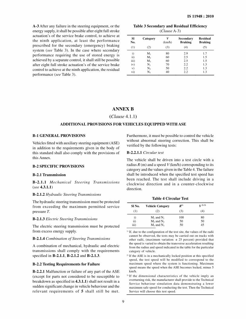
A-3 After any failure in the steering equipment, or theenergy supply, it shall be possible after eight full strokeactuation’s of the service brake control, to achieve atthe ninth application, at least the performanceprescribed for the secondary (emergency) brakingsystem (see Table 3). In the case where secondaryperformance requiring the use of stored energy isachieved by a separate control, it shall still be possibleafter eight full stroke actuation’s of the service brakecontrol to achieve at the ninth application, the residualperformance (see Table 3).
Table 3 Secondary and Residual Efficiency(Clause A-3)
Sl No.
Category V (km/h)
Secondary Braking
Residual Braking
(1) (2) (3) (4) (5)
i) ii) iii) iv) v) vi)
M1 M2
M3 N1 N2 N3
80 60 60 70 50 40
2.9 2.5 2.5 2.2 2.2 2.2
1.7 1.5 1.5 1.3 1.3 1.3
B-1 GENERAL PROVISIONS
Vehicles fitted with auxiliary steering equipment (ASE)in addition to the requirements given in the body ofthis standard shall also comply with the provisions ofthis Annex.
B-2 SPECIFIC PROVISIONS
B-2.1 Transmission
B-2.1.1 Mechanical Steering Transmissions(see 4.3.1.1)
B-2.1.2 Hydraulic Steering Transmissions
The hydraulic steering transmission must be protectedfrom exceeding the maximum permitted servicepressure T.
B-2.1.3 Electric Steering Transmissions
The electric steering transmission must be protectedfrom excess energy supply.
B-2.1.4 Combination of Steering Transmissions
A combination of mechanical, hydraulic and electrictransmissions shall comply with the requirementsspecified in B-2.1.1, B-2.1.2 and B-2.1.3.
B-2.2 Testing Requirements for Failure
B-2.2.1 Malfunction or failure of any part of the ASE(except for parts not considered to be susceptible tobreakdown as specified in 4.3.1.1) shall not result in asudden significant change in vehicle behaviour and therelevant requirements of 5 shall still be met.
Furthermore, it must be possible to control the vehiclewithout abnormal steering correction. This shall beverified by the following tests:
B-2.2.1.1 Circular test
The vehicle shall be driven into a test circle with aradius R (m) and a speed V (km/h) corresponding to itscategory and the values given in the Table 4. The failureshall be introduced when the specified test speed hasbeen reached. The test shall include driving in aclockwise direction and in a counter-clockwisedirection.
Table 4 Circular Test
Sl No. Vehicle Category R1) V 2) 3)
(1) (2) (3) (4)
i) M1 and N1 100 80 ii) M2 and N2 50 50
iii) M3 and N3 50 45
1) If, due to the configuration of the test site, the values of the radiicannot be observed, the tests may be carried out on tracks withother radii, (maximum variation: ± 25 percent) provided thatthe speed is varied to obtain the transverse acceleration resultingfrom the radius and speed indicated in the table for the particularcategory of vehicle.
2) If the ASE is in a mechanically locked position at this specifiedspeed, the test speed will be modified to correspond to themaximum speed where the system is functioning. Maximumspeed means the speed when the ASE becomes locked, minus 5km/h.
3) If the dimensional characteristics of the vehicle imply anoverturning risk, the manufacturer shall provide to the TechnicalService behaviour simulation data demonstrating a lowermaximum safe speed for conducting the test. Then the TechnicalService will choose this test speed.
10
IS 11948 : 2010
ANNEX C
(Clause 4.1.1)
PROVISIONS FOR TRAILERS HAVING HYDRAULIC STEERING TRANSMISSIONS
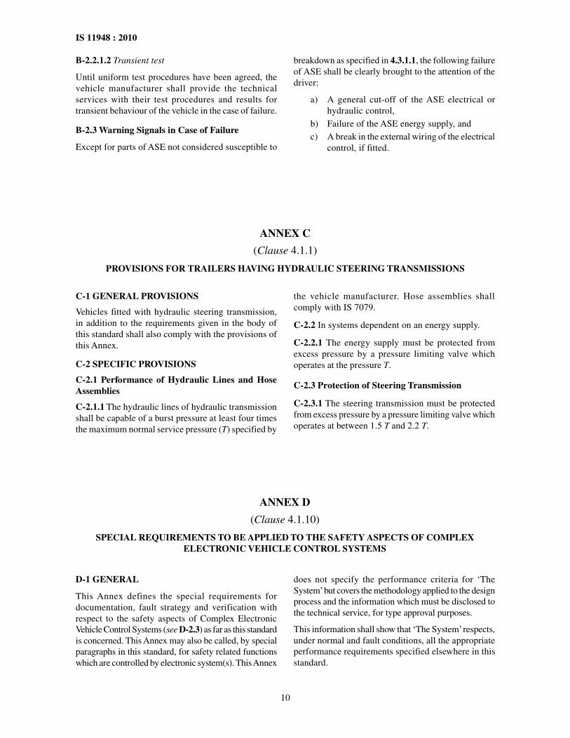
B-2.2.1.2 Transient test
Until uniform test procedures have been agreed, thevehicle manufacturer shall provide the technicalservices with their test procedures and results fortransient behaviour of the vehicle in the case of failure.
B-2.3 Warning Signals in Case of Failure
Except for parts of ASE not considered susceptible to
breakdown as specified in 4.3.1.1, the following failureof ASE shall be clearly brought to the attention of thedriver:
a) A general cut-off of the ASE electrical orhydraulic control,
b) Failure of the ASE energy supply, andc) A break in the external wiring of the electrical
control, if fitted.
C-1 GENERAL PROVISIONS
Vehicles fitted with hydraulic steering transmission,in addition to the requirements given in the body ofthis standard shall also comply with the provisions ofthis Annex.
C-2 SPECIFIC PROVISIONS
C-2.1 Performance of Hydraulic Lines and HoseAssemblies
C-2.1.1 The hydraulic lines of hydraulic transmissionshall be capable of a burst pressure at least four timesthe maximum normal service pressure (T) specified by
the vehicle manufacturer. Hose assemblies shallcomply with IS 7079.
C-2.2 In systems dependent on an energy supply.
C-2.2.1 The energy supply must be protected fromexcess pressure by a pressure limiting valve whichoperates at the pressure T.
C-2.3 Protection of Steering Transmission
C-2.3.1 The steering transmission must be protectedfrom excess pressure by a pressure limiting valve whichoperates at between 1.5 T and 2.2 T.
ANNEX D
(Clause 4.1.10)
SPECIAL REQUIREMENTS TO BE APPLIED TO THE SAFETY ASPECTS OF COMPLEXELECTRONIC VEHICLE CONTROL SYSTEMS
D-1 GENERAL
This Annex defines the special requirements fordocumentation, fault strategy and verification withrespect to the safety aspects of Complex ElectronicVehicle Control Systems (see D-2.3) as far as this standardis concerned. This Annex may also be called, by specialparagraphs in this standard, for safety related functionswhich are controlled by electronic system(s). This Annex
does not specify the performance criteria for ‘TheSystem’ but covers the methodology applied to the designprocess and the information which must be disclosed tothe technical service, for type approval purposes.
This information shall show that ‘The System’ respects,under normal and fault conditions, all the appropriateperformance requirements specified elsewhere in thisstandard.
11
IS 11948 : 2010
D-2 DEFINITIONS
For the purposes of this Annex following definitionsshall apply:
D-2.1 Safety Concept, is a description of the measuresdesigned into the system, for example within theelectronic units, so as to address system integrity andthereby ensure safe operation even in the event of anelectrical failure.
The possibility of a fall-back to partial operation oreven to a back-up system for vital vehicle functionsmay be a part of the safety concept.
D-2.2 Electronic Control System, means acombination of units, designed to co-operate in theproduction of the stated vehicle control function byelectronic data processing.
Such systems, often controlled by software, are builtfrom discrete functional components such as sensors,electronic control units and actuators and connectedby transmission links. They may include mechanical,electro-pneumatic or electro-hydraulic elements. ‘TheSystem’, referred to herein, is the one for which typeapproval is being sought.
D-2.3 Complex Electronic Vehicle Control Systems,are those electronic control systems which are subjectto a hierarchy of control in which a controlled functionmay be over-ridden by a higher level electronic controlsystem/function. A function which is over-riddenbecomes part of the complex system.
D-2.4 Higher-Level Control, systems/functions arethose which employ additional processing and/orsensing provisions to modify vehicle behaviour bycommanding variations in the normal function(s) ofthe vehicle control system. This allows complexsystems to automatically change their objectives witha priority which depends on the sensed circumstances.
D-2.5 Units, are the smallest divisions of systemcomponents which will be considered in this Annex,since these combinations of components will be treatedas single entities for purposes of identification, analysisor replacement.
D-2.6 Transmission Links, are the means used forinter-connecting distributed units for the purpose ofconveying signals, operating data or an energy supply.
This equipment is generally electrical but may, in somepart, be mechanical, pneumatic or hydraulic.
D-2.7 Range of Control, refers to an output variableand defines the range over which the system is likelyto exercise control.
D-2.8 Boundary of Functional Operation, definesthe boundaries of the external physical limits withinwhich the system is able to maintain control.
D-3 DOCUMENTATION
D-3.1 Requirements
The manufacturer shall provide a documentationpackage which gives access to the basic design of ‘TheSystem’ and the means by which it is linked to othervehicle systems or by which it directly controls outputvariables. The function(s) of ‘The System’ and thesafety concept, as laid down by the manufacturer, shallbe explained. Documentation shall be brief, yet provideevidence that the design and development has had thebenefit of expertise from all the system fields that areinvolved. For periodic technical inspections, thedocumentation shall describe how the currentoperational status of ‘The System’ can be checked.
D-3.1.1 Documentation shall be made available in twoparts:
a) The formal documentation package for theapproval, containing the material listed in D-3(with the exception of that of D-3.4.4) whichshall be supplied to the technical service atthe time of submission of the type approvalapplication. This will be taken as the basicreference for the verification process set outin D-4.
b) Additional material and analysis dataof D-3.4.4 which shall be retained by themanufacturer, but made open for inspectionat the time of type approval.
D-3.2 Description of the functions of ‘The System’
A description shall be provided which gives a simpleexplanation of all the control functions of ‘The System’and the methods employed to achieve the objectives,including a statement of the mechanism(s) by whichcontrol is exercised.
D-3.2.1 A list of all input and sensed variables shall beprovided and the working range of these defined.
D-3.2.2 A list of all output variables which arecontrolled by ‘The System’ shall be provided and anindication given, in each case, of whether the controlis direct or via another vehicle system. The range ofcontrol (see D-2.7) exercised on each such variableshall be defined.
D-3.2.3 Limits defining the boundaries of functionaloperation (see D-2.8) shall be stated where appropriateto system performance.
D-3.3 System Layout and Schematics
D-3.3.1 Inventory of Components
A list shall be provided, collating all the units of ‘TheSystem’ and mentioning the other vehicle systems,
12
IS 11948 : 2010
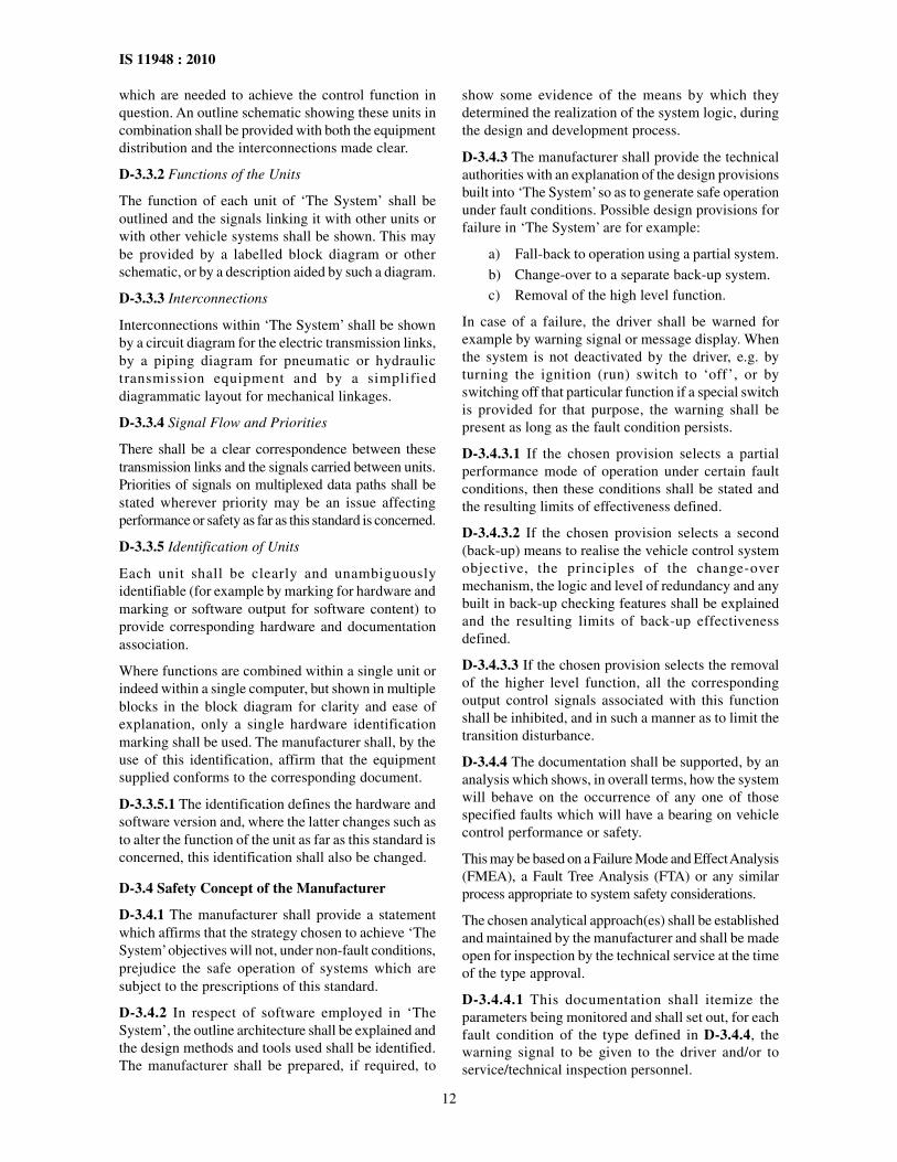
which are needed to achieve the control function inquestion. An outline schematic showing these units incombination shall be provided with both the equipmentdistribution and the interconnections made clear.
D-3.3.2 Functions of the Units
The function of each unit of ‘The System’ shall beoutlined and the signals linking it with other units orwith other vehicle systems shall be shown. This maybe provided by a labelled block diagram or otherschematic, or by a description aided by such a diagram.
D-3.3.3 Interconnections
Interconnections within ‘The System’ shall be shownby a circuit diagram for the electric transmission links,by a piping diagram for pneumatic or hydraulictransmission equipment and by a simplifieddiagrammatic layout for mechanical linkages.
D-3.3.4 Signal Flow and Priorities
There shall be a clear correspondence between thesetransmission links and the signals carried between units.Priorities of signals on multiplexed data paths shall bestated wherever priority may be an issue affectingperformance or safety as far as this standard is concerned.
D-3.3.5 Identification of Units
Each unit shall be clearly and unambiguouslyidentifiable (for example by marking for hardware andmarking or software output for software content) toprovide corresponding hardware and documentationassociation.
Where functions are combined within a single unit orindeed within a single computer, but shown in multipleblocks in the block diagram for clarity and ease ofexplanation, only a single hardware identificationmarking shall be used. The manufacturer shall, by theuse of this identification, affirm that the equipmentsupplied conforms to the corresponding document.
D-3.3.5.1 The identification defines the hardware andsoftware version and, where the latter changes such asto alter the function of the unit as far as this standard isconcerned, this identification shall also be changed.
D-3.4 Safety Concept of the Manufacturer
D-3.4.1 The manufacturer shall provide a statementwhich affirms that the strategy chosen to achieve ‘TheSystem’ objectives will not, under non-fault conditions,prejudice the safe operation of systems which aresubject to the prescriptions of this standard.
D-3.4.2 In respect of software employed in ‘TheSystem’, the outline architecture shall be explained andthe design methods and tools used shall be identified.The manufacturer shall be prepared, if required, to
show some evidence of the means by which theydetermined the realization of the system logic, duringthe design and development process.
D-3.4.3 The manufacturer shall provide the technicalauthorities with an explanation of the design provisionsbuilt into ‘The System’ so as to generate safe operationunder fault conditions. Possible design provisions forfailure in ‘The System’ are for example:
a) Fall-back to operation using a partial system.
b) Change-over to a separate back-up system.c) Removal of the high level function.
In case of a failure, the driver shall be warned forexample by warning signal or message display. Whenthe system is not deactivated by the driver, e.g. byturning the ignition (run) switch to ‘off’, or byswitching off that particular function if a special switchis provided for that purpose, the warning shall bepresent as long as the fault condition persists.
D-3.4.3.1 If the chosen provision selects a partialperformance mode of operation under certain faultconditions, then these conditions shall be stated andthe resulting limits of effectiveness defined.
D-3.4.3.2 If the chosen provision selects a second(back-up) means to realise the vehicle control systemobjective, the principles of the change-overmechanism, the logic and level of redundancy and anybuilt in back-up checking features shall be explainedand the resulting limits of back-up effectivenessdefined.
D-3.4.3.3 If the chosen provision selects the removalof the higher level function, all the correspondingoutput control signals associated with this functionshall be inhibited, and in such a manner as to limit thetransition disturbance.
D-3.4.4 The documentation shall be supported, by ananalysis which shows, in overall terms, how the systemwill behave on the occurrence of any one of thosespecified faults which will have a bearing on vehiclecontrol performance or safety.
This may be based on a Failure Mode and Effect Analysis(FMEA), a Fault Tree Analysis (FTA) or any similarprocess appropriate to system safety considerations.
The chosen analytical approach(es) shall be establishedand maintained by the manufacturer and shall be madeopen for inspection by the technical service at the timeof the type approval.
D-3.4.4.1 This documentation shall itemize theparameters being monitored and shall set out, for eachfault condition of the type defined in D-3.4.4, thewarning signal to be given to the driver and/or toservice/technical inspection personnel.
13
IS 11948 : 2010
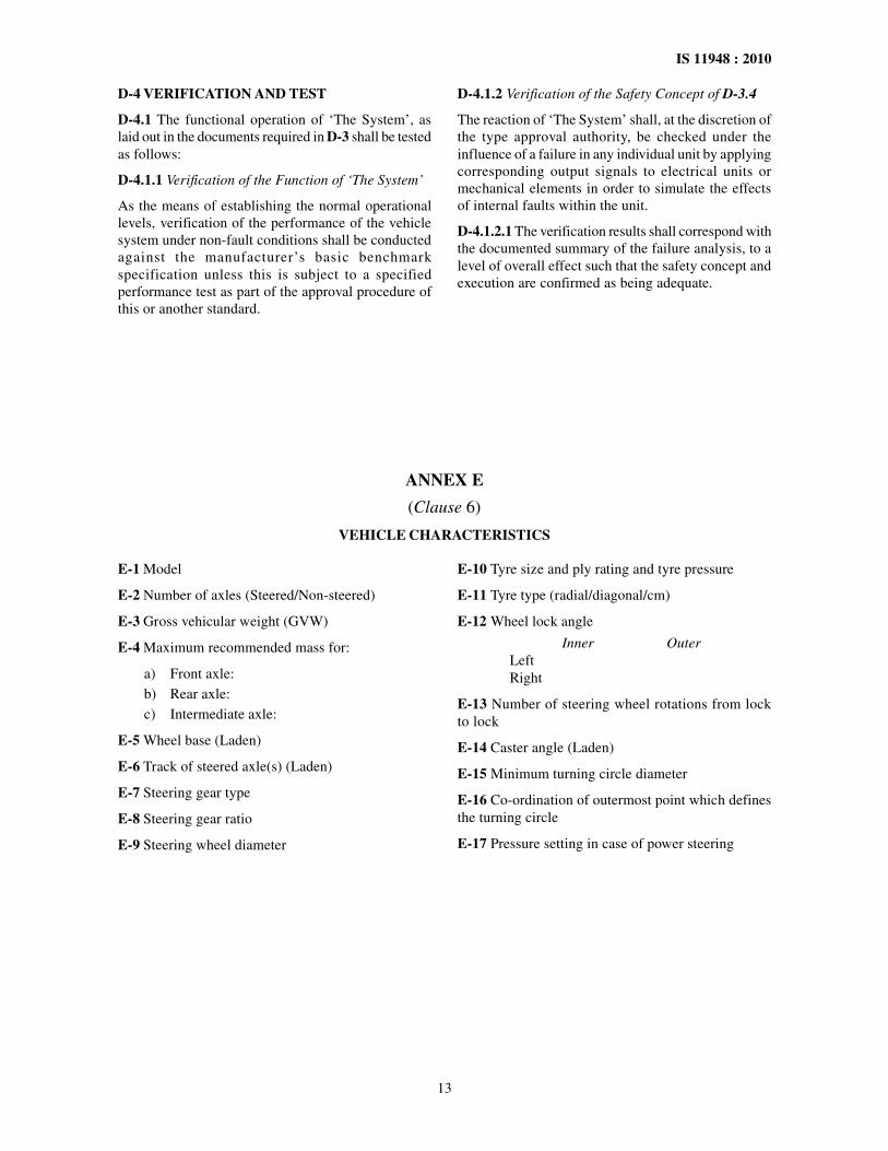
D-4 VERIFICATION AND TEST
D-4.1 The functional operation of ‘The System’, aslaid out in the documents required in D-3 shall be testedas follows:
D-4.1.1 Verification of the Function of ‘The System’
As the means of establishing the normal operationallevels, verification of the performance of the vehiclesystem under non-fault conditions shall be conductedagainst the manufacturer’s basic benchmarkspecification unless this is subject to a specifiedperformance test as part of the approval procedure ofthis or another standard.
ANNEX E
(Clause 6)
VEHICLE CHARACTERISTICS
E-1 Model
E-2 Number of axles (Steered/Non-steered)
E-3 Gross vehicular weight (GVW)
E-4 Maximum recommended mass for:
a) Front axle:b) Rear axle:c) Intermediate axle:
E-5 Wheel base (Laden)
E-6 Track of steered axle(s) (Laden)
E-7 Steering gear type
E-8 Steering gear ratio
E-9 Steering wheel diameter
E-10 Tyre size and ply rating and tyre pressure
E-11 Tyre type (radial/diagonal/cm)
E-12 Wheel lock angle
Inner OuterLeftRight
E-13 Number of steering wheel rotations from lockto lock
E-14 Caster angle (Laden)
E-15 Minimum turning circle diameter
E-16 Co-ordination of outermost point which definesthe turning circle
E-17 Pressure setting in case of power steering
D-4.1.2 Verification of the Safety Concept of D-3.4
The reaction of ‘The System’ shall, at the discretion ofthe type approval authority, be checked under theinfluence of a failure in any individual unit by applyingcorresponding output signals to electrical units ormechanical elements in order to simulate the effectsof internal faults within the unit.
D-4.1.2.1 The verification results shall correspond withthe documented summary of the failure analysis, to alevel of overall effect such that the safety concept andexecution are confirmed as being adequate.
Bureau of Indian Standards
BIS is a statutory institution established under the Bureau of Indian Standards Act, 1986 to promoteharmonious development of the activities of standardization, marking and quality certification of goodsand attending to connected matters in the country.
Copyright
BIS has the copyright of all its publications. No part of these publications may be reproduced in any formwithout the prior permission in writing of BIS. This does not preclude the free use, in the course ofimplementing the standard, of necessary details, such as symbols and sizes, type or grade designations.Enquiries relating to copyright be addressed to the Director (Publications), BIS.
Review of Indian Standards
Amendments are issued to standards as the need arises on the basis of comments. Standards are also reviewedperiodically; a standard along with amendments is reaffirmed when such review indicates that no changes areneeded; if the review indicates that changes are needed, it is taken up for revision. Users of Indian Standardsshould ascertain that they are in possession of the latest amendments or edition by referring to the latest issue of‘BIS Catalogue’ and ‘Standards : Monthly Additions’.
This Indian Standard has been developed from Doc No.: TED 4 (644).
Amendments Issued Since Publication
Amend No. Date of Issue Text Affected
BUREAU OF INDIAN STANDARDS
Headquarters:
Manak Bhavan, 9 Bahadur Shah Zafar Marg, New Delhi 110 002Telephones : 2323 0131, 2323 3375, 2323 9402 Website: www.bis.org.in
Regional Offices: Telephones
Central : Manak Bhavan, 9 Bahadur Shah Zafar Marg 2323 7617NEW DELHI 110002 2323 3841
Eastern : 1/14 C.I.T. Scheme VII M, V. I. P. Road, Kankurgachi 2337 8499, 2337 8561KOLKATA 700054 2337 8626, 2337 9120
Northern : SCO 335-336, Sector 34-A, CHANDIGARH 160022 60 384360 9285
Southern : C.I.T. Campus, IV Cross Road, CHENNAI 600113 2254 1216, 2254 14422254 2519, 2254 2315
Western : Manakalaya, E9 MIDC, Marol, Andheri (East) 2832 9295, 2832 7858MUMBAI 400093 2832 7891, 2832 7892
Branches: AHMEDABAD. BANGALORE. BHOPAL. BHUBANESHWAR. COIMBATORE. DEHRADUN.FARIDABAD. GHAZIABAD. GUWAHATI. HYDERABAD. JAIPUR. KANPUR. LUCKNOW.NAGPUR.PARWANOO. PATNA. PUNE. RAJKOT. THIRUVANANTHAPURAM.VISAKHAPATNAM.
�
��
�
�
Laser Typeset by Sunshine Graphics