IS 11772 (2009): Design of drainage arrangements of energy ...
22
Disclosure to Promote the Right To Information Whereas the Parliament of India has set out to provide a practical regime of right to information for citizens to secure access to information under the control of public authorities, in order to promote transparency and accountability in the working of every public authority, and whereas the attached publication of the Bureau of Indian Standards is of particular interest to the public, particularly disadvantaged communities and those engaged in the pursuit of education and knowledge, the attached public safety standard is made available to promote the timely dissemination of this information in an accurate manner to the public. इंटरनेट मानक “!ान $ एक न’ भारत का +नम-ण” Satyanarayan Gangaram Pitroda “Invent a New India Using Knowledge” “प0रा1 को छोड न’ 5 तरफ” Jawaharlal Nehru “Step Out From the Old to the New” “जान1 का अ+धकार, जी1 का अ+धकार” Mazdoor Kisan Shakti Sangathan “The Right to Information, The Right to Live” “!ान एक ऐसा खजाना > जो कभी च0राया नहB जा सकता ह ै” Bhartṛhari—Nītiśatakam “Knowledge is such a treasure which cannot be stolen” IS 11772 (2009): Design of drainage arrangements of energy dissipators and training walls of spillways - Guidelines [WRD 9: Dams and Spillways]
Transcript of IS 11772 (2009): Design of drainage arrangements of energy ...

Disclosure to Promote the Right To Information
Whereas the Parliament of India has set out to provide a practical regime of right to information for citizens to secure access to information under the control of public authorities, in order to promote transparency and accountability in the working of every public authority, and whereas the attached publication of the Bureau of Indian Standards is of particular interest to the public, particularly disadvantaged communities and those engaged in the pursuit of education and knowledge, the attached public safety standard is made available to promote the timely dissemination of this information in an accurate manner to the public.
इंटरनेट मानक
“!ान $ एक न' भारत का +नम-ण”Satyanarayan Gangaram Pitroda
“Invent a New India Using Knowledge”
“प0रा1 को छोड न' 5 तरफ”Jawaharlal Nehru
“Step Out From the Old to the New”
“जान1 का अ+धकार, जी1 का अ+धकार”Mazdoor Kisan Shakti Sangathan
“The Right to Information, The Right to Live”
“!ान एक ऐसा खजाना > जो कभी च0राया नहB जा सकता है”Bhartṛhari—Nītiśatakam
“Knowledge is such a treasure which cannot be stolen”
“Invent a New India Using Knowledge”
है”ह”ह
IS 11772 (2009): Design of drainage arrangements of energydissipators and training walls of spillways - Guidelines[WRD 9: Dams and Spillways]


IS 11772: 2009
~~~ 3,~ ~ ~~ ctfc;r etr m-m~q{~3lT cB- ~\J1I~~ - ~cf~
( 4t5C'1f Ffrerur )
Indian Standard
DESIGN OFDRAINAGE ARRANGEMENTS OFENERGYDISSIPATORS AND TRAINING WALLS OF
SPILLWAYS - GUIDELINES
( First Revision)
res 93 .16
© BIS 2009
BUREAU OF INDIAN STANDARDSMANAK BHA VAN, 9 BAHADUR SHAH ZAFAR MARG
NEW DELHI r 10002
Jun e 2009 Price Group 7

Dams and Spillways Sectional Committee. WRD 9
FOREWORD
This Indian Standard (First Revision) was adopted by the Bureau of Indian Standards, after the draft finaliz ed bythe Dams and Spillways Sectional Committee had been approved by the Water Resources Divi sion Coun cil.
Energy dissipators for dams involve problems of ero sion of foundation material on their downstream side andoccurrence of excess seepage under them . The compl exity of these problems depends upon type, stratification,permeability, homogeneity and other characteri stics of the foundat ion material as well as size and physicalrequirements of the energy dissipators.
The probable hydrost atic uplift torees. under adverse cond itions, on the ene rgy dissipators parti all y re lieved bytheir drainage system , shall be estimated conservatively considering charac teristics of their foundations anddrain age systems.
The critical condition may be channel empty after rapid closure of gates of a gated sp illway or dropping ofreservoir level to crest of an ungated spillway with water in foundations at maximum gradient under applicablereservoir conditions, or water flowing from a spillway under design flood.
This standard was first published in 1986. This revision is being taken up in order to incor porate the knowledgegained during the use of this standard. The main changes incorporated in this revision are as under:
In Fig. 4, the inlet of the drainage outlet on the face of the spillway was shown preceded with one eyebrow. Thispresence of the eyebrow on the surface of the high velocity flow at the toe of the spillway was observed to behighly objectionable as it may lead to cavitation damage. Therefore in this revision suitable modifications havebeen made in 3.2.4 and Fig . 4.
For the purpose of deciding whether a particular requirement of this standard is complied with , the final value.observed or calculated, expre ssing the result s of a test or analysis , shall be rounded off in accordanc e withIS 2 : 1960 'Rules for rounding off numerical values (revised)' . The number of significant places retained in therounded off value should he the same as that of the specified value in this standard .
IS 11772 ; 2009
Indian Standard
DESIGN OF DRAINAGE ARRANGEMENTS OF ENERGYDISSIPATORS AND TRAINING WALLS OF
SPILLWAYS - GUIDELINES
( First Revision)
IS No.5186: 1994
1SCOPE
1.1 Th is standard covers guidelines for drainage aspectsof energy dissipators and training wall s of spillways.
1.2 Various energy dissipators covered are :
a) Buckets - roller (sol id and slotted. and skijump type); and
b) Stilling basins - sloping and horizontalaprons.
1.3 Drainage aspects of chutes have been covered inIS 5186.
2 REFERENCE
The following standard contains provisions. whichthrough reference in this text , con stitutes provision ofthis standard. At the time of publication, the ed itionindicated was valid. All standards are subject to revision.and parties to agreements based on this standard areencouraged to investigate the possibility of applyingthe most recent edition of the standard indicated below :
TitleDesign of chute and s ide channelsp illwa ys - Cr iter ia (first revision)
3 TERMINOLOGY
For the purpose of this standard. the followingdefinitions shall apply.
3.1 Drainage - Safe removal of excess seepage waterbelow an energy dissipation structure. or from behinda training wall.
3.2 Filter - A layer or a combination of layers ofgraded pervious materials designed and placed in sucha manner as to provide drainage and yet prevent themovement of soil particles with seepage water.
3.3 Uplift Pressure - The upward hydraul ic pressurein the pores of a body (pore or interstitial pressure ) oron the base of an energy dissip ator or a training wall.
4 DRAINAGE ASPECTS FOR ENERGY DL5SIPAlURS
4.1 Uplift Forces. Dynamic Pressures and Drainage
4.1.1 Due 10 reservoir upstream of a dam and tailwater
downstream. upl ift pressures besides occurring asinternal pressures in pores. cracks and scam s of damfoundati on s and in the body of the dam also occurunder its ,energy dissipators.
4.1.2 The pore spaces in foundation mater ial belowthe energy d issipaters get filled with water which exertspressures in all directions. Such pressures depend uponhead of water in the reservoir and also on tailwaterhead . Phen omena like micro turbulence due to highvelocity flows over panelled dissipater or flows orearthquakes may also affect the uplift pressures.
4.1.3 With proper care. uplift pressures on the energydi ssipators can be minimized by pro viding weep holes.surface drains, drainage holes in foundation rock andproviding relief well s in pervious foundations.
4.1.4 In case of energy dissipators, weight of concretefloor and anchorage to the rock . if provided. shall bedesigned to with stand uplift and dynamic pressureswith ample factor of safety to take care of limitationsin accurate evaluation of such pressures.
4.1.5 Liberal allowances shall be made for maximumprobable uplift pressures and quantity of seepage waterfor foundat ion material under the mo st adverseheadwater. tailwater, with or without groundwaterconditions for de sign of drainage systems for theenergy dis sipators with an ample factor of safety.
4.1.6 Drainage aspects of buckets, either roller orski-jump type and stilling basins shall be essentiallysimilar but shall be governed by tailwater heads andtypes of their foundation strata.
4.1.7 For a properly designed dam, a well plannedcurtain grouting programme is normally env isaged forits foundation . Although such well planned groutingprogramme may materially reduce seepage through thefoundat ion, some means shall be provided to interceptwater which may percolate through and around thegrout curtain and which, if not removed, may buildhigh hydrostatic pressures on its energy dissipator.
4.1.8 Dra inage is provided under floor slabs of energyd issipat ers to reduce upl ift pressures . Effe ct ivedra inage . below the energy dissipaters generally limitsuplift pressur es to required design limits. The degree

IS 11772 : 2009
of effectiveness of the drainage systems depends uponcharacteristics of foundation material anddependability of their effective maintenance.
4.1.9 Sometimes, under the special conditions referredto in 4.4.1, drainage galleries, sumps, etc, may beprovided below the energy dissipators of large dams ,if considered necessary.
4.2 Drainage Holes and Drains for EnergyDissipators
4.2.1 Common schemes for drain age of foundationmaterial below floor slabs of the energy d,issipatorsare:
a) Providingverticalformedholes or pipes throughfloorslabs (this is the simplest scheme and maybe used for minor works) (see Fig. 1),
b) A grid of half round pipe drains or tile drainsalong the foundation surface (may beadequate for low heads) (see Fig . 2),
c) Drain holes drilled into the foundation rockor relief wells into pervious foundation materialin combination with formed holes or pipesthrough floor slabs (preferable for higher headsand sound formation) (see Fig. 3). and
d) An elaborate system for large major projectsas described in 4.4.
4.2.2 Formed holes or pipes for relief of uplift pressureare provided through the floor slabs. Their spacing mayvary from 2 to 5 m in both directions (see Fig. I) .
4.2.3 The grid of half round drains shall follow thealignment of vertical or incl ined drain holes. ifprovided, to facilitate collection and di sposal ofpercolat ing water from them . The grid of half rounddrains shall be of minimum 200 mm diameter, leadingwater to relatively larger diameter collector half rounddrains or galleries/sumps near the upstream and/ordownstream ends of the energy dissipators and/or nearthe training walls.
4.2.4 Large diameter collector half round drains nearupstream and/or downstream ends of the energydissipators and/or near the training walls at both theirends shall be connected to outlets. These drains releasewater either hy pressure or by gravity flow throughoutle ts provid ed on the down stream o f energydis sipator s and /or sides of the tr ain ing walls asindicated (see Fig. 4). The outlets provided to dischargethe water collected into the half round drains shall beprovided with non-return valves flush with the exitsurface.
4.2.5 The grid of half round drains and/or largedi am et er collector half round dra ins shall bealternatively connected with galleries below the energy
2
dissipators to lead water into sumps or directly intosumps generally provided below the energy dissipatorsand/or on backs ides of the end training wall s. Water ispumped out from sumps for its disposal from suitablelocations above the maximum tail water level.
4.2.6 Each collector drain shall have at least two orpreferably more outlets so that all drains may functionsatisfactorily e ve n if some outlets get choked up(see Fig. 4) .
4.2.7 The half round drains may either be vitreous clayor plain co ncrete pipes and shall be laid in gradedmaterial wh ich act s as filter . or on sub-grade asrecommended in 3.3.1.
4.2.8 The drains holes are usually NX holes (75 mmdiameter). They shall be drilled after completion ofthe foundation grouting in their vicinity, if any , to avoidtheir clogging.
4.2.9 The vertical drain holes shall be adopted wherejoints and stratification in foundation rock havecomplex or dominantly horizontal pattern . The inclineddra in holes sha ll be adopted where jo ints andstratificat ions in foundation rock have dominantlyinclin ed pattern.
4.2.10 The spacing of drain holes may vary from 3to 10m in both directions and their depth may varyfrom 20 to 40 percent of tailwater depth when no othersupporting data is available. The spacing shall be clo serfor rocks hav ing low permeability.
4.2.11 In case detailed studies about joints andstratification in foundation rocks. the ir permeabilityand anticipated quantity of seepage from them havebeen made, the depth of vertical or inclined drain holesshall be based on such studies. These holes shall beconnected to a grid of half round drains and/or drainsin galleries under the energy dissipators.
4.2.12 The horizontal drain holes shall be preferredwhere joints and stratification in foundation rock ha:ea dominantly vertical pattern . The horizontal dramholes shall be drilled into foundation rock from thegallery either perpendicular to its al ignment or in afan shape with a gentle slope towards the gallery foreasy disposal of percolating water. The depth of suchholes may be up to 20 m or more depending on ease ofdrilling and subsequent maintenance for their effectivefunctioning (see Fig . 5).
4.3 Sub-grade and Outlets for Drains
4.3.1 The sub-grade under half round pipe drainsshall consist of porous concrete pad laid to requiredgrades. wherever necessary, on foundat ion rock to
receive half round vitreous clay pipes/plain concretepipes.

IS 11772 : 2009
FRl
* SPACING MAY VARYFROM 2 TO Sm etcBOTHWAYS
TOP OF DAM
TOP OF ENDTRAINING WAll
...-----STlllING
FIG. 1 R ELIEF H OLES IN TH E APRON FLOOR
TOP OF END TRAINING WALL
GRID OF HALF ROUNDPIPE DRAINS
I
75mm DIAMETER DRAINAGE HOLES -----::::::..---SPACING MAY VARY FROM 3 TO 10 m
Ctc BOTHWAYS
Fur, 2 DR AINi\{jE HOt ES D RILl .LO I:'-:TO THE R OC K

IS 11772 : 2009
FRL--------
GL
I
ep lS0mm PERFORATED --llSEWER PIPE DRAIN-----II
CONTRACTIONJOINT
I
': ItI ~
I~ II
<P150mm RELIEF/I
WELLS
"300mm GRAVELBLANKET
FIG. 3 RELIEF WELLS IN PERVIOUS FOUNDATIONS
I.1
II
II.. rI
I~.,11
II
"
II~
II
GRID OF ct:> 200 mm HALF ROUNDPIPE DRAIN ( ct:> 200 mm min)
TOP OF TRAININGWALL
DRAIN HOLES --.n---+--~-_u.-_~_rt-~""'-'
ep 300mm HALF ROUNDCOLLECTOR PIPES '\
FRL
FIG. 4 DRAINAGE O UTLETS IN STILLING BASIN
4.3.2 The half round pipes may he directly placed onfounda tion rock where ver feas ible . The por ousconcrete may be used under the half round pipes formaintaining proper connections among them andmaintaining their levels and grades.
4.3.3 Different alternative arrangements for laying thehalf round drains are shown in Fig . 6A, 6B and 6C.
4.3.4 Gravel blankets, wherever provided, shall be wellgraded to prevent movement of foundat ion material
with flow of seepage wate r.
4.3.5 Seepage water collected in drain s below theenerg)' dissipators may be disposed of by one or more
of the follow ing common methods:
4

IS 11772 : 2009
L6·0mt
6·0m-+
6·0m
GALlERY(1·Sm x2·Sm)
ar.. ~<\ »x\' ,.,_________ ~~~~__ ZD\1 Z~\' '»<'( >~-""",,,,,",....,t'1
I -Z-- ----------------~---===';,J,l
HORIZONTAL DRAINS
~~e:::===---~----==::=:::::::~~ J~~f-e:=~=--~~-=::::::==----==::::::~L.a:::::. t 1·5 m
FIG. 5 TYPICAL SCHEME SHOWING HORIZONTAL DRAINS
NO FI NE POROUSCONCRETE COVERTO KEEP HALFROUND PIPES INPOSITION WHILEMAIN CONCRETING
MAIN CONCRETE OFENERGY DISSIPATOR
POROUS CONCRETE PADFOR RECEIVING DRAINAGEPIPES ON UNEVENROCK SURFACE
FILLING WITH GRAVEL OPTIONAL,NECESSARY IN CASES WHERE THEDRILL HOLE CANNOT STAND
\\-oI----~:..-::,*-'....---?1-- HALF ROUND .A ..u.--r-.,.-......--~~...IL- CONCRETE PIPE
T/7'~:.I-... ¢ 200 mm min
UNEVEN ROCK SURFACEBELOW STILLING BASINOR ENERGY DISSIPATOR
6A Details for Laying of Half Round Pipe Drains (Alternative Arrangement 1)
FIG. 6 HALF ROUND PIPE DRAINS - Continued
5

IS 11772: 2009
UNEVEN ROCK SURFACEBELOW ENERGX DISSIPATOR
DRY CONCRETE TOPREVENT MORTARFROM ENT~RrNG
PIPE
. -.' ... ;: . , ... . 'A:· ,...... Jj •
'", .
4'600 mm HALF ROUNDDRAIN PIPES
-"""""-+--MAIN CONCRETEOF ENERGYDISSIPATOR
POROUS CONCRETE PADLAID FOR RECt:IVINGDRAINAGE PIPES ONUNEVEN ROCK SURFACE
68 Details for Laying of Half Round Pipe Drains (Alternative Arrangement 2)
POROUS CONCRETE PAD LAIDFOR RECEIVING DRAINAGE PIPESON UNEVEN ROCK SURFACE
MAIN CONCRETE OFENERGY DISSIPATOR
.. to ••
~'I""----
. ~
HALF ROUNDCONCRETE PIPE-h-....:--~---/-::..-_~p-~
UNEVEN ROCK SURFACEBELO W STILLING BASINOR ENERGY DISSIPATOR
.A' • ~
TAR PAPER/BUILDING PAPERTO PROTECT SLURRYENTERING FILTER
--+-- SAND ANDGRAVEL FILTER
6e Details for Laying of Half Round Pipe Drains (Alternative Arrangement 3)
NOTES
I Half round pipe drains shall be placed directly on rock wherever possible .
2 Porous concrete shall be used under pipes wherever necessary so as to maintain proper grade and connect ion of pipe.
FIG. 6 HALF ROUND PIPE DRAINS
a) Outlets discharging seepage water by gravity:
I) Outlets through dentated sills for stillingbasins (see Fig. 4),
2) Outlets from down stream face of sill ofski-j ump bucket (see Fig. 7A).
3) Outlets from down stream face of sill ofslotted roller bucket (see Fig . 78),
4) Outlets from down stream face of sill ofsol id roller bucket (see Fig. 7C), and
b) Outlets d ischarging see page water bypumping from sumps provided below thestilling basinslbuckets and/or behind the endtraining wall s.
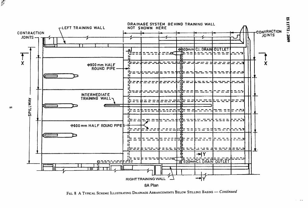
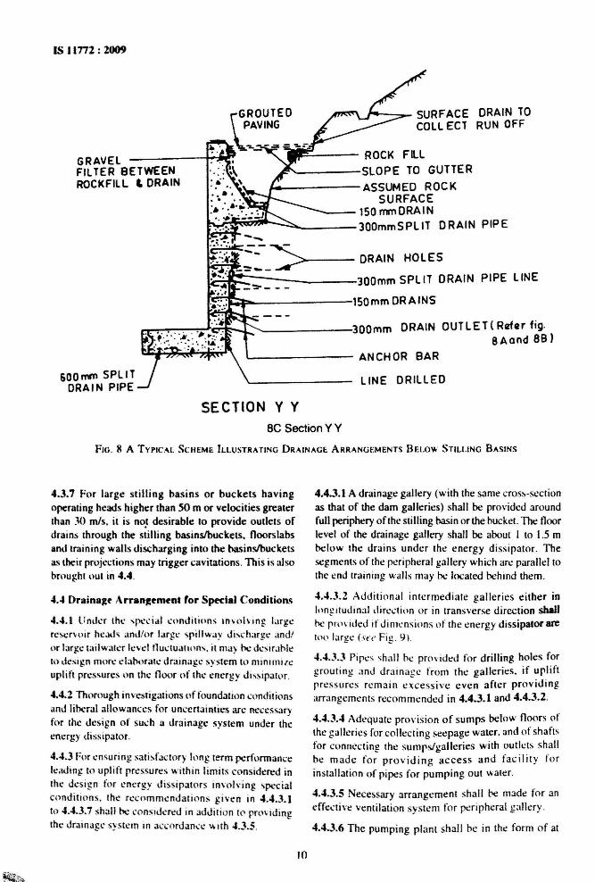
4.3.6 A typ ical sche me illustrating the drainagearrangement of half round pipes below a stilli ngbasin and behind a training wall , hav ing outletsd ischarging into the stilling basin is shown inFig. 8A, 88 and sc.

IS 11772 : 2009
DRAINAGE OUTLET
HALF ROUNDCOLLECTORPIPE DRAIN
TOP OF TRAINING WALL
".1ORAINAGE HOLEs-...+t'l--..-!I,.,
7A Drain Outlet for Ski-Jump Bucket
GRID OF HALFROUND PIPE DRAIN
TOP OF TRAININGWALL
DRAINAGEOUTlET
HALF ROUNDCOLLECTOR PIPEDRAIN
7B Drain Outlet for Slotted Roller Bucket
I'.:II
DRAINAGE HOLES --..Iit-I----.
TOP OF TRAINING WAlL
DRAINAGE OUTLET
:~ ::~NAGEHOLES
7C Drainage Holes in Solid Roller Bucket
FIG. 7 DRAIN O UTLET FOR BUCKETS
7
~
§
....~ONTRACTION
JOINTS
fX
DRAINAGE SYSTEM BEHIND TRAINING WALLroo
nON \ I I I I ~ C.I ~ I J I , I J 101 I~- II I' I I \ r r ,
..... II I I I
-rJ--- c!l GOOmm C.1. DRAI~ OUTLET---- == tr ~ :.-:..-_-:. - - -- ..-_-_-;1ro- -- - --- ----
-'- II II
I~=: -=-=---...; ---- ...:::; L..._ -=-== =======--'"'c;.900mm HALF r- --II I I
ROUND PIPE I I I1'-__-~----= :. -::.-:: :.. -'~-- -::...-_-::..-:: ':. -::..-::. =- ~ .::.:.::J
{(---:. .. - - , --p " II 1-'-IL __~ ----=--- ..J L. _ ' . :.- - - - ---- ":--:_"'J,.- - -- -- -- -- -1 r-- --- ---IIII I I
-'- I L __I~':.= ,;; - --- ::-:.----- -, =.--- --- - ~ :":'-.J--- - ""\ r- -- ---
INTERMEDIATE ,I I -'-TRAINING WALL" I
=~IL. -- .::=== ---- L __ ---- - -,...- ... _ .:"J,.-- ---- ... -- - --- -- ... -I I I::::I
1'- - - ;. ': ': ':..-..; -'::.,':.:-.:-. -' ~-- :.-----=---- -- -- z:_-_-.Jr-- ..... r -- -- --I'
-'-I ,
1:===---- ::---_-::.." _I1.. __
::"--:...--- - - -'- -_-_-:'"3- -- 1 r -- ----ep600mm HALF ROUND PIPES !~_-.:- I :
=-:::_J .L. __
"===.= -- -- -----"- --- ... .... -- ----, -'-I , l::l Ii... __ I
-:. ~-_-:.. - ---- -J ~ -- -- - - z:--- -_'::. z:_"":.::J10- -- - - - -- l t-- - ---,I. . I1'-- __ =--- - =:.-:. :.-:.1=:...-- ..:: --== = "::: =..--- ==:"'-...::1--- - -- ,...J"
II I I +tVIL __ - ': -=---:. -::..----"q Co -_-_ ..:;_-_-.:..: - --- ..:___-..:1
r;:------- -.=1:-= -- a: 600mmC.1. ORAI~ OUTLET- -- ----,.--, I I I IiI J I II J
r: 111 \IL
Y r ,\ I
~~-'...J
e,VI
rX
CONTRACJOINTS
oe
SA Plan
FIG. 8 A TYPICAL SCHEME ILLUSTRATING DRAINAGE ARRANGEMENTS BELOW STILLING BASINS - Continued

--~
ENDTRAININGWALL
.p300mmG1 PIPEDRAIN OUTLET
SECTION BS
HALF ROUNDDRAIN PIPE
'=-_.IC!!r.0;:;....;O~. -,,:,-. -:,: : "' , •.a....a. '. ; .: I ' , :~: :,, • "1: 'T"""j: " , I -'J ' " ..:.'."", 'i I: "··' I··'~ ' '
'.... ,,__cf»300mm -r ':". I I., ;~" 'J. ':",DRAIN "::,. ,:, :=t I: .: :: ': :~.OUTLET ~•. :'L ~. 'f' .•' ',:& • •-- ", .,) : '-.:
I I
" I-__.;=,l-_{1.. I
==.::.~•
SECTION C C300mm DRAINS
SECTION
88 Section XX
DRAIN OUTLET
Bj-J.C
BI-HALF ROUNDPIPE DRAIN
,..---END TRAINING WALL --'""\
J-.---......,-----I+----1I----4+---,..~--_t- CONTRACTIONJOINTS
DETAIL A
FIG , 8 A TYPICAL SCHEME ILLUSTRATING DRAINAGE ARRANGEMENTS BELOW STILLING BASINS - Continued
IS 11rn : 1009
"""--.._ SURFACE DRAIN TOCOLL ECl RUN OFF
ROCK FilL,I:!'.....----SlOPE TO GUTTER
~---------ASSUMED ROCKSURFACE
----150 mmDRAIN~~""'-'::::::::""'-----300mmSPlIT DRAIN PIPE
r-.-,"""",,"--:-",",,:,,:,.l-t:!~....l. ......---------300mm DRAIN aun E T( Rczfer fig.8Aand 88)
ANCHOR BAR
LINE DRILLED
GRAVELFILTER BETWEENROCKFILL .. DRAIN
600 mrn SPLI TDRAIN PIPE
SECTION V VBe Section Y Y
FIG . 8 A TYPICAL SC:HEME ILLUSTRATING DRAINAGE ARRANGEMENTS BELOW STILLING BASINS
4.3.7 For large st illing bas ins or buckets havingoperating heads higher than 50 m or velocities greaterIhan 30 mls. it is no.t desirable to provide outlets ofdrains through the stilling basins/buckets, floorslabsand training walls discharging into the basinslbucketsas their project ions may trigger cavitations. Th is is alsobrought out in 4.4.
...4 Draina~t' Arrangement for Special Conditions
...... 1 Under the special cond it ion s inv olv ing liugercserv o ir he.Kls and/or lar ge spillway discharge: and/or large tailwatcr level Iluctu auons, it may I'Cdesirahleto design more elaborate drainage system to minimizeuplift pressures on the floor of the energy dissipater .
...... 2 Thorough investigations of foundation conditionsand liberal allowances for uncertainties arc necessarvfor the design of such a dra inage system under theenergy dissipater,
4.4.3 For ensuring satisfactory long term performancelead ing [ 0 uplift pressures ..... ithin limits co nsidered inthe design for energy dissip aters invol ving specialcond itions . Ihe recomme nda tio ns given in 4.4.3.1to 4"'.3.7 shall be cons rdcred in addition to providingthe drainage system in acc ordance w ith 4.3 .5 .
4.4.3.1 A drainage gallery (with the same cross- sectionas that of the dam galleries) shall be provided aroundfull periphery of the stilling basin or the bucket. The floorlevel of the drainage gallery shall be about I to 1.5 mbelow the dra ins under the energy dissipator. Thesegments of the peripheral gallery which arc parallel tothe end training walls may he located behind them.
4.4.3.2 Additional intermediate galleries either inhlng itudin al dire ct ion or in transverse direction shallbe provided If dimensions of the energy dissipator arc10 0 large (S ('( , Fig. 9 ).
4.4.03.3 Pipe s shall he provided for drilling holes forgrouting and dr ain age from the galleries. if upliftpressures remain e xcess ive even after provid ingarrangements recommended in 4.4.3.1 and 4.4.3.2.
4.4.3.4 Adequate provision of sumps below floors ofthe galleries for collecting seepage water. and of shaftsfor connecting the sumps/galleries with outlets shallhe madc for pr oviding access and facilit y forinstall ation of pipes for pumping out water.
4.4.3.5 Necessary arrangement shall be made for aneffective ventilation sys tem for per ipheral gallery.
4.4 .3.6 The pumping plant shall he in the form of at
10

-~--........,N
f- - TYPICAL BAYSSHOWING SPACINGOF VERTICALDRAINS
;:::.;=-"I-- END SIL L
~~tJ\. R'IGHT
TRAINING WAll
r TRAi l NINGWALL
~tP
-+-+--CONTRACTIOHJOINTS
.....-t--PERIPHERAlGAllERY
ii .,
II "___'L JL- -If - - - - ·-iT" ,I:: .'
SUMP AND PUMPING ~ IPLANT ROOM ~ j
STRAIGHT PORTION REVERSEGRADE:
I, "
I. .. i, r t \I•• I I ~: t,__'L L __ ~ __IL J "- .J,--,r -----tT-- ---..-----'r ----,,'FLOW', ;1 , .'~~ ~ II :: '1 1:II II .. " I,,. II " " •__ .JL ~ __ ---P---o:--~ J.
--ir------tj-- .--~-- --~-----i'
__ -'L -'L.£_- """r - - - - - ... r --
I, 'II' III !:
,. 'I___JL J L __- -:. - - - - ,r - -
" "I, '.. ~,
•
~SUMP AND PUMPING~. PLANT ROOM
"
II r :'_ .-11. __ ... _0.1._--'r------I--
" II:. I,.1 "
" i l
I, I'___ ..... ..Il_
--:f - - - -If-
I SlOPIN~~ PORTION
'+-MIO GALlkRY l: ;. HALF ~ c .. ~ 0 - Q . ----rr, OPTIONAL .:': I~.rt-~Ir,~ROUND pIPE OOAINSi :: ::__ JL __ ~. __ ..IL .IL _ --II.- J' ~ __ .Jl.. JI.- .-1,
-- -lr - -I- - -If - - -. ·,r - -,r - - - - -,~ --- "'--;r --~ . -Jr- - - - - -1',I II " II " I' I. fl., I, ", II II , '. .1, 'i ,I " II !I " I
~J
Y :'I- _-JL._-- --'T --I,:.
~ -:.= F ==~~ -:. -= -:: --i:= == =----~~=,I " IIII " ::"
'I \I II " i I, II I, h• II " J' • II "______ JL ..IL JL L JL JL -J"-I= J,'
- -- - - -, ... - - - - - "."" - - - - Ij - - .. - - - - - -'r - - - - -'r - -- -"If''"r- - - - -1" " Ii ;1 ~" :;.J " i'
LEFT TRAINING WALL
-'--.
-t------...,..--
z~S!:z:: .... ~...
~!Z-'
...J ::0 0::- Q.Z
~., .... 0
Vl0
Sf~
-:z::......J0 TZ0 ~~
9A Plan
FI G,9 RROA O OllTUM' 01 ~ T, ,'rc" t . G ."II FRY SYSTIM ' 0 11 A M"JOR PR O/I TT - - Continued

......~
GRAVITYWALL SECTION
TOE GALLERY
PANEL WALLSECTION
GRID OF ROUND CONCRETE PIPESOF DRAINS LEADING TO GALLERYAND SUMP
TOP OF TRAINING WALL
.... ..... .........~, ......jl .... ~..... ..... ..... :--......--------L-y----+------r-------r---j--,-IIJ. '~... .....11'"~ ~.... ' ~F= ;: =-:-='f:::=:-::--=='=::~¥'==--=:iF :n=-:..TF-=:_-tl '::::~ .... ,I h II •• :'1 '-:,'J::.=::. =-=tl:: =..-.:;: '" = ':!I=:' ::-.:~ _ .::1)::. -:..~.-:.'::" ,i 'J II I' T.1 I I • II IIII " ,I II Jt ••
' .... ~ I " II ':1 9,'li'I ....~~.....' II II 'I :'............. '" L JI. .11... h.JLII .......'"=..""~;:: === _=- it::::---F?_'=L'=-tj=-.= -=-=="CF_ :'-Q:--£-ttt-::'':
:: 'iI II II :: I', • II II !l. 11I~.... 'I I, " ~ w
.... :::::..... II II I, /I II,~- " 11 1 II..... _===...="= =__-=- I
PERIPHERAL GALLERYI:NTRV OF HALF ROUND PIPE DRAINSINTO THE GALLERY SHALL BE ATLEASTO'8m TO l·OmeD) ABOVE THE flOORLEVEL SO AS TO FACILITATE CLEANING
N
GRID OF HALF ROUNDPIPES BELOW STILLING ~BASIN I_I
c#l600 mm HALFROUND PIPE DRAIN
DETAILS OF TOE GALLERY
SECTION A A
-'1>600 mm HALFROUND PIPE DRAIN
-1__ 2·5m
.~ 1~
DETAILS OF CENTRAL GALLERY98 Longitudinal Section
FIG. 9 BROAD OUTLINE OF A TYPICAL GALLERY SYSTEM FOR A MAJOR PROJECT _ Continued

IS 11772 : 2009
ANCHORBARS
DRAIN HOLES
_1--- SELECTE DMATERIAL FORBACK FILLING
ORIGINALGROUND SURFACE
__---t---:;:-- POCKET DRAINS
~__ DRAINAGE HOLES
9C Section 88
---.,r-- -IIII,I'1
GRID OF HALFROUND PIPE BELOWSTILLING BASIN
DRAINAGEGALLERY
rr--GRID OF ROUN,l---.......1CONCRETE PIPES :=~-:.~_OF DRAIN S lE ADING I
TO GALLERY AND ~~-..:==SUMP I
1L _
--
CONCRETEPAVING
NOTE - The dr ain di scharge from under the energy dissipater and behind the tra ining wall is co llec ted into the gallery andfinall y into the su mp from where it is pumped out.
FIG. 9 BROAD OUTLINE OF A TYPICAL GALLERY SYSTEM FOR A MAJOR PROJ ECT
least two pump units at each location for disposing ofseepage water. It shall have an overall factor for safetyof at least four in terms of capac ity of pumping.
4.4.3.7 An independent access shall be provided forthe galleries below the floor of the energy dissipator.
4.4.4 A broad outline ofa typical gallery system suitablefor a large energy dissipator is shown in Fig. 9.
4.5 Surface Drainage for Energy Dissipators
4.5.1 Sumps with streaml ined profiles may he providedclose to train ing walls in low-vel ocity area in stillinghasin s/buckels to facilit at e their dew ater ing forinspection and maintenance.
4.5.2 Where practicable, drain pipes may he providedto dispose of standing water and toreduce pumpingcosts during inspection.
5 DRAINAGE ASPECTS OF TRAINING WALLS
5.1 General
Training walls of the following types are generallyprovided with energy diss ipator s:
a) Gravity/cantilever walls, and
h) Anchored training walls .
5.1.1 Hydrostat ic forces may develop on the trainingwalls of energy dissipaters due to acc umulation ofseepage water behind them .
[3

IS 11772 : 2009
5.1.2 Suitable drainage arrangements shall be providedto control or minimize saturation of backfill materialand to reduce hydrostatic forces on the training walls.They shall be designed with liberal dimensions andsuitable provisions against clogging.
5.2 Gravity or Cantilever Training Walls
5.2.1 Drainage behind the training walls may beeffected by providing either permeable backfill .pockets, channels in two directions. a continuousblanket . inclined drain s. enveloping drains . etc. usingfreely draining well-graded material.
5.2.2 The conveying units to dispose of seepage waterfrom backsides of the training walls may either be weepholes or longitudinal perforated vitreous clay orcorrugated galvanized steel sheet pipe drains. The weepholes through the walls may convey the water collectedfrom different arrangements behind the walls asmentioned in 5.2.3 and discharge it in front. Thelongitudinal drains may convey water to the point fromwhere it may be disposed of by gravity flow or mayconvey it to sumps from which it may be pumped topoints from where it may be disposed ofby gravity flow.
5.2.3 The commonly adopted types of drainagearrangements for the training walls are illustrated inFig. 10. In cases where outlets are provided to dischargeinto stilling basins/buckets, they may he provided withnon-return valves :
a) A simple system may consist of weep holesthrough the training walls (see Fig. lOA). The :weep holes may consist of either vitreous claypipes/concrete pipes/GI pipes. 100 mm ormore in diameter. The ir spacing may varyfrom 1.5 to 5.0 m in both directions. Thissystem is suitable for backfill consisting ofpermeable material which drains freely. Atthe entry to each weep hole, a grill protectedby a suitable filter shall be provided to preventthe weep hole from getting clogged up.
b) For backfill which is not SUfficientlypermeable. pockets ofcoarse material may beplaced around the end of each weep hole tofacilitate drainage (see Fig . lOB). A moreelaborate arrangement ma y providecontinuous horizontal channel of coarse
14
material, along inner ends of weep hole ssupplemented by vertical channels (0. 3 m xOJ m square section) placed midway betweenthe weep holes, with their lower end s joiningthe horizontal ' channel (see Fig . 10C). Tofurther increase effectiveness, the entirebackside of a training wall may be coveredwith 300 mm thick gravel blanket (see Fig.IOD).
c) An inclined drain provided is relatively moreeffect ive as it reduces both earth pressure andseepage (see Fig. IOE).
d) For a backfill of expansive soils, an envelopedrain may be provided (see Fig . IOF). Thissyste m minimizes changes in moisturecontent in the backfill.
5.2.4 The drainage system behind the training wallsshall not create a short seepage path to the downstreamside of the main control section.
5.3 Drainage Arrangements for Special Conditions
For training walls of large stilling basins or bucketshaving operating heads higher than 50 m or velocitiesgreater than 30 mis, outlets of weep holes shall not beprovided projecting on inside face of the training wallsas their project ions may trigger cavitation. In suchcases , the drainage arrangements for training walls maybe integrated with the drainage arrangements of thestilling basins/buckets or the outlets which conveywater to galleries/sumps from where it may be pumpedout (see Fig. 9C).
5.4 Anchored Training Walls
5.4.1 For concrete/masonry anchored tra ining walls,adequate drilled holes shall be provided in the rockbehind them to drain seepage water and to relievehydrostatic pressures that may develop due tosaturation.
5.4.2 If the drain holes are not used, transverse tile (orequivalent) drains along the rock profile with headersand outlets shall be provided for drainage of seepagewater and for relief of hydrostatic pressures that maydevelop due to saturation. The common arrangementsfor drainage of anchored training walls are illustratedin Fig. II and 12.

HORIZONTALCHANNEL
IMPERVIOUSMATERIAL,
'c4-0·3xO·3mVERTICAL" CHANNEL MIDWAY, BETWEEN WEEP-
HOLES
WEEP HOLESONLY
lOA lOB laC
v;
PORTIONPERMANENTLYDRAINED
CONTINUOUSBLANKET0·3 m THICK
,tA--GRAVELBLANKET
~
FIG. 10 TYPICAL BACKFULL DRAINS FOR GRAVITY TYPE TRAINING W ALLLS OF ENERGY DISSIPATORS
100 10E 10F......::iN..i

IS 11772 : 2009
SLOPE TO
CONCRETE ANCHOREDj GUTTERTRAINING WALL
--- ==:''":.a,....I_--'--
1c:'~7lf=::::::::"b_ _300rnmHAL F ROUNDDRAIN PIPE
IC-:-';"::":~!::::::::--+--'50mm HALF ROUNDVERTICAL DRAINS
DRAIN HOLES IN ROCK
ep300mm DRAIN HOLES
NOTES
1 Drain outlet shall be on similar lines as shown in Fig. 88 .
2 As an alternative, when outlets are provided to discharge into stilling basins/bucket, they may be provided with non-return valves.
FIG. II COMMON ARRANGEMENTS FOR DRAINAGE OF ANCHORED TRAINING WALLS
r,:-:=-.. DRAINAGE HOLES::::L-=_-=_-=_r--i---=~ IN ROCKr--
ANCHOR BARS
-- - -
IL. _
1;--- ---- -11..__I~--
GRID OF spurDRAINS BELOWSllLLING BASIN
DRAINAGEGALLERY
- -'1P' ----oiu II
l! !;-.-- DRAINAGE HOLES
NOTE - The drain discharge from under the energy dissipater and behmd the training wall is collected into the gallery and finally intothe sump from where it is pumped out.
F IG. 12 ARRANGEMENTS FOR DRAINAG E OF A NCHORED TRAINING WALLS
(With Reference to 4.4)
16
GMGIPN-147 BIS/ND/~300

Bureau of Indian Standards
BIS is a statutory institution established under the Bureau of Indian Standards Act , 1986 to promoteharmonious development of the activities of standardization, marking and quality certification of goodsand attending to connected matters in the country.
Copyright
BIS has the copyright of all its publications. No part of these publications may be reproduced in any formwithout the prior permission in writing of BIS . This does not preclude the free use, in the course ofimplementing the standard, of necessary details, such as symbols and sizes , type or grade designations.Enquiries relating to copyright be addressed to the Director (Publications), BIS.
Review of Indian Standards
~\\
Amendments are issued to standards as the need arises on the basis of comments. Standards are also reviewedperiodically ; a standard along with amendments is reaffirmed when such review indicates that no changes areneeded; if the review indicates that changes are needed, it is taken up for revision . Users of Indian Standa~dsshould ascertain that they are in possession of the latest amendments or edition by referring to the latest issue of'BIS Catalogue' and 'Standards : Monthly Additions' .
This Indian Standard has been developed from Doc No.: WRD 9 (324)...~
Amendments Issued Since Publication
Amend No. Date of Issue Text Affected
BUREAU OF INDIAN STANDARDS
Headquarters:
Manak Bhavan, 9 Bahadur Shah Zafar Marg, New Delhi I 10002Telephones: 2323 0131,2323 3375,2323 9402 Website: www.bis .org.in
Telephones
1114 C.I.T. Scheme VII M, V. I. P. Road, KankurgachiKOLKATA 700054
Manak Bhavan, 9 Bahadur Shah Zafar MargNEW DELHI 110002
SCO 335-336, Sector 34-A, CHANDIGARH 160022
C.IT. Campus , IV Cross Road, CHENNAI 600113
{2323 76 1723233841
{2337 8499 ,2337856123378626,23379120
{60 3843609285
{2254 1216,2254 144222542519,22542315
Manakalaya, E9 MIDC, Marol, Andheri (East) {2832 9295, 2832 7858MUMBAI 400093 2832 7891, 2832 7892
AHMEDABAD. BANGALORE. BHOPAL. BHUBANESHWAR. COIMBATORE. FARIDABAD.GHAZI~BAD. GUWAHATI. HYDERABAD. JAIPUR. KANPUR. LUCKNOW. NAGPUR.PARWANOO. PATNA. PUNE. RAJKOT. THIRUVANANTHAPURAM. VISAKHAPATNAM.
Regional Offices:
Central
Eastern
Northern
Western
Branches:
Southern
PRINTED BY THE GENERAL MANAGER, GOVT. Of INDIA PRESS, NASHIK.....22 006