IS 10187 (2002): Hydraulic Fluid Power - Four-Port ...
23
Disclosure to Promote the Right To Information Whereas the Parliament of India has set out to provide a practical regime of right to information for citizens to secure access to information under the control of public authorities, in order to promote transparency and accountability in the working of every public authority, and whereas the attached publication of the Bureau of Indian Standards is of particular interest to the public, particularly disadvantaged communities and those engaged in the pursuit of education and knowledge, the attached public safety standard is made available to promote the timely dissemination of this information in an accurate manner to the public. इंटरनेट मानक “!ान $ एक न’ भारत का +नम-ण” Satyanarayan Gangaram Pitroda “Invent a New India Using Knowledge” “प0रा1 को छोड न’ 5 तरफ” Jawaharlal Nehru “Step Out From the Old to the New” “जान1 का अ+धकार, जी1 का अ+धकार” Mazdoor Kisan Shakti Sangathan “The Right to Information, The Right to Live” “!ान एक ऐसा खजाना > जो कभी च0राया नहB जा सकता ह ै” Bhartṛhari—Nītiśatakam “Knowledge is such a treasure which cannot be stolen” IS 10187 (2002): Hydraulic Fluid Power - Four-Port Directional Control Valves - Mounting Surfaces [PGD 16: Fluid Power]
Transcript of IS 10187 (2002): Hydraulic Fluid Power - Four-Port ...

Disclosure to Promote the Right To Information
Whereas the Parliament of India has set out to provide a practical regime of right to information for citizens to secure access to information under the control of public authorities, in order to promote transparency and accountability in the working of every public authority, and whereas the attached publication of the Bureau of Indian Standards is of particular interest to the public, particularly disadvantaged communities and those engaged in the pursuit of education and knowledge, the attached public safety standard is made available to promote the timely dissemination of this information in an accurate manner to the public.
इंटरनेट मानक
“!ान $ एक न' भारत का +नम-ण”Satyanarayan Gangaram Pitroda
“Invent a New India Using Knowledge”
“प0रा1 को छोड न' 5 तरफ”Jawaharlal Nehru
“Step Out From the Old to the New”
“जान1 का अ+धकार, जी1 का अ+धकार”Mazdoor Kisan Shakti Sangathan
“The Right to Information, The Right to Live”
“!ान एक ऐसा खजाना > जो कभी च0राया नहB जा सकता है”Bhartṛhari—Nītiśatakam
“Knowledge is such a treasure which cannot be stolen”
“Invent a New India Using Knowledge”
है”ह”ह
IS 10187 (2002): Hydraulic Fluid Power - Four-PortDirectional Control Valves - Mounting Surfaces [PGD 16:Fluid Power]


Hkkjrh; ekud
æo pkfyr rjy 'kfDr — pkj Nsn okys fn'kkRedfu;a=kd okYo — vkjksi.k lrgsa
( nwljk iqujh{k.k )
Indian Standard
HYDRAULIC FLUID POWER —FOUR-PORT DIRECTIONAL CONTROL VALVES —
MOUNTING SURFACES
( Second Revision )
ICS 23.100.30
© BIS 2013
February 2013 Price Group 7
B U R E A U O F I N D I A N S T A N D A R D SMANAK BHAVAN, 9 BAHADUR SHAH ZAFAR MARG
NEW DELHI 110002
IS 10187 : 2013
ISO 4401 : 2005
Fluid Power Systems Sectional Committee, PGD 16
NATIONAL FOREWORD
This Indian Standard (Second Revision) which is identical with ISO 4401 : 2005 ‘Hydraulic fluid power— Four-port directional control valves — Mounting surfaces’ issued by the International Organizationfor Standardization (ISO) was adopted by the Bureau of Indian Standards on the recommendation ofthe Fluid Power Systems Sectional Committee and approval of the Production and General EngineeringDivision Council.
This standard was originally published in 1982 based on ISO 4401 : 1980 and subsequently revisedin 2000 based on ISO 4401 : 1994. This second revision has been harmonized with ISO 4401 : 2005by adoption to make pace with the latest developments that have taken place at international level.
The text of ISO Standard has been approved as suitable for publication as an Indian Standard withoutdeviations. Certain terminology and conventions are, however, not identical to those used in IndianStandards. Attention is particularly drawn to the following:
a) Wherever the words ‘International Standard’ appear, referring to this standard, they should beread as ‘Indian Standard’.
b) Comma (,) has been used as a decimal marker while in Indian Standards the current practiceis to use a point (.) as the decimal marker.
In this adopted standard, reference appears to certain International Standards for which IndianStandards also exist. The corresponding Indian Standards, which are to be substituted in theirrespective places, are listed below along with their degree of equivalence for the editions indicated:
International Standard Corresponding Indian Standard Degree of Equivalence
ISO 286-2 : 19881 ) ISO system oflimits and fits — Part 2: Tables ofstandard tolerances grades and limitdeviations for holes and shafts
ISO 4287 : 1997 Geometrical ProductSpecifications (GPS) — Surfacetexture: Profile method — Terms,definit ions and surface textureparameters
ISO 5598:19852 ) Fluid powersystems and components —Vocabulary
IS 919 (Part 2) : 1993 ISO system oflimits and fits: Part 2 Tables ofstandard tolerances grades and limitdeviations for holes and shafts (first
revision)
IS 15262 : 2002 Geometrical productspecifications (GPS) — Surfacetexture: Profile method — Terms,definit ions and surface textureparameters
IS 10416 : 1992 Fluid power systemsand components — Vocabulary (first
revision)
Identical
do
do
The technical committee has reviewed the provisions of the following International Standards referredin this adopted standard and has decided that they are acceptable for use in conjunction with thisstandard:
International Standard Title
ISO 1101 : 2004 Geometrical Product Specifications (GPS) — Geometrical tolerancing —Tolerances of form, orientation, location and run-out
ISO 1302 : 2002 Geometrical Product Specifications (GPS) — Indication of surface texturein technical product documentation
ISO 5783 : 1995 Hydraulic fluid power — Code for identification of valve mounting surfacesand cartridge valve cavities
1) Since revised in 2010.2) Since revised in 2008. (Continued on third cover)

1 Scope
This International Standard specifies the dimensions and other data relating to surfaces on which four-port hydraulic directional control valves are mounted in order to ensure their interchangeability.
It applies to mounting surfaces for four-port hydraulic directional control valves which represent current practice. They are generally applicable to industrial equipment.
2 Normative references
The following referenced documents are indispensable for the application of this document. For dated references, only the edition cited applies. For undated references, the latest edition of the referenced document (including any amendments) applies.
ISO 286-2, ISO system of limits and fits — Part 2: Tables of standard tolerance grades and limit deviations for holes and shafts
ISO 1101, Geometrical Product Specifications (GPS) — Geometrical tolerancing — Tolerances of form, orientation, location and run-out
ISO 1302, Geometrical Product Specifications (GPS) — Indication of surface texture in technical product documentation
ISO 4287, Geometrical Product Specifications (GPS) — Surface texture: Profile method — Terms, definitions and surface texture parameters.
ISO 5598, Fluid power systems and components — Vocabulary
ISO 5783, Hydraulic fluid power — Code for identification of valve mounting surfaces and cartridge valve cavities
3 Terms and definitions
For the purposes of this document, the terms and definitions given in ISO 5598 apply.
Indian Standard
HYDRAULIC FLUID POWER —FOUR-PORT DIRECTIONAL CONTROL VALVES —
MOUNTING SURFACES
( Second Revision )
IS 10187 : 2013
ISO 4401 : 2005
1

4 Symbols
4.1 For the purposes of this International Standard, the following symbols apply:
A, B, L, P, T, T1, X and Y identify ports;
F1, F2, F3, F4, F5 and F6 identify threaded holes for fixing cap screws (bolts) (see footnote a in the figures);
G, G1, G2 identify locating pin holes.
4.2 An explanation for the codes is given in ISO 5783.
5 Tolerances
5.1 The following values shall be applied to the mounting surface, i.e. that area within dotted bold lines:
surface roughness: Ra u 0,8 µm as specified in ISO 1302 and ISO 4287;
surface flatness: 0,01 mm over a distance of 100 mm, as specified in ISO 1101;
tolerance for diameter of locating pin hole: H12 in accordance with ISO 286-2.
5.2 The following tolerances shall be complied with along the x- and y-axes with respect to the origin:
pin holes and bolt holes: ± 0,1 mm;
port holes: ± 0,2 mm.
As for the other dimensions, see the figures.
6 Dimensions
6.1 The mounting surface dimensions for hydraulic directional control valves with four service ports shall be selected from the figures and tables specified in 6.2 to 6.7.
6.2 Mounting surface dimensions for control valves with four service ports with 4,5 mm maximum port diameter (4401–02–01–0–05), are given in Figure 1 and Table 1.
6.3 Mounting surface dimensions for control valves with four service ports with 7,5 mm maximum port diameter:
a) without pilot port (4401–03–02–0–05), are given in Figure 2 and Table 2;
b) with pilot ports (4401–03–03–0–05), are given in Figure 3 and Table 3.
6.4 Mounting surface dimensions for control valves with four service ports with 11,2 mm maximum port diameter:
a) without pilot port (4401–05–04–0–05), are given in Figure 4 and Table 4;
b) with pilot ports (4401–05–05–0–05), are given in Figure 5 and Table 5;
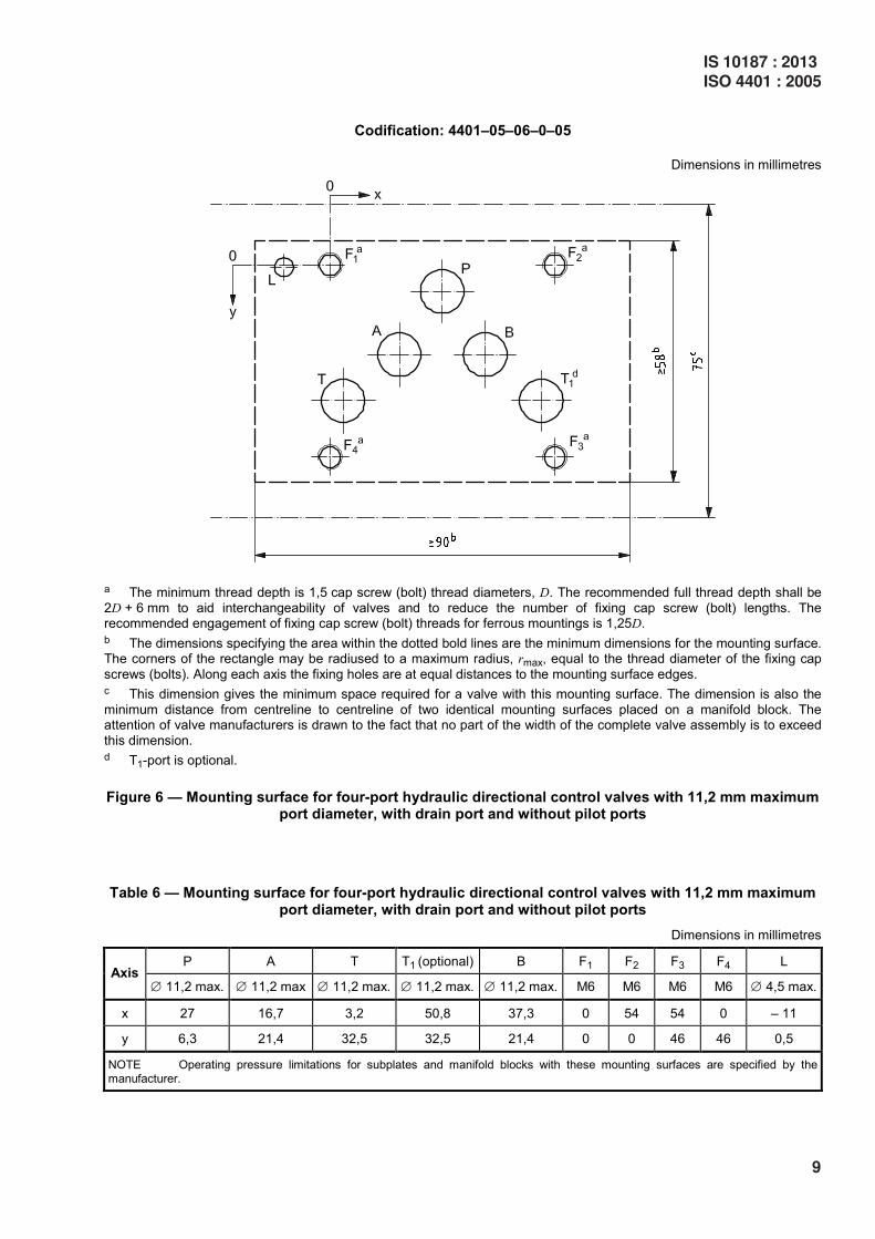
c) with drain port and without pilot ports (4401–05–06–0–05), are given in Figure 6 and Table 6.
2
IS 10187 : 2013
ISO 4401 : 2005

6.5 Mounting surface dimensions for control valves with four service ports with pilot ports and with 17,5 mm maximum port diameter, with or without drain ports (4401–07–07–0–05), are given in Figure 7 and Table 7.
6.6 Mounting surface dimensions for control valves with four service ports with pilot ports and with 25 mm maximum port diameter, with or without drain ports (4401–08–08–0–05), are given in Figure 8 and Table 8.
6.7 Mounting surface dimensions for control valves with four service ports with pilot ports and with 32 mm maximum port diameter, with or without drain ports (4401–10–09–0–05), are given in Figure 9 and Table 9.
7 Pressure limitations
Operating pressure limitations for subplates and manifold blocks with these mounting surfaces shall be established by the manufacturer.
8 Identification statement (reference to this International Standard)
Use the following statement in test reports, catalogues and sales literature when electing to comply with this International Standard:
“Mounting surface dimensions conform to ISO 4401:2005, Hydraulic fluid power — Four-port directional control valves — Mounting surfaces”
IS 10187 : 2013
ISO 4401 : 2005
3

Codification: 4401–02–01–0–05
Dimensions in millimetres
a The minimum thread depth is 1,5 bolt diameters, D. The recommended full thread depth shall be 2D + 6 mm to aid
interchangeability of valves and to reduce the number of fixing bolt lengths. The recommended engagement of fixing cap screw (bolt) threads for ferrous mountings is 1,25D.
b The dimensions specifying the area within the dotted bold lines are the minimum dimensions for the mounting surface. The corners of the rectangle may be radiused to a maximum radius, rmax, equal to the thread diameter of the fixing cap
screws (bolts). Along each axis the fixing holes are at equal distances to the mounting surface edges. c This dimension gives the minimum space required for a valve with this mounting surface. The dimension is also the
minimum distance from centreline to centreline of two identical mounting surfaces placed on a manifold block. The attention of valve manufacturers is drawn to the fact that no part of the width of the complete valve assembly is to exceed
this dimension.
Figure 1 — Mounting surface for four-port hydraulic directional control valves with 4,5 mm maximum port diameter
Table 1 — Mounting surface for four-port hydraulic directional control valves with 4,5 mm maximum port diameter
Dimensions in millimetres
P A T B F1 F2 F3 F4 G a Axis ∅ 4,5 max. ∅ 4,5 max. ∅ 4,5 max. ∅ 4,5 max. M5 M5 M5 M5 ∅ 3,4
x 12 4,3 12 19,7 0 24 24 0 26,5
y 20,25 11,25 2,25 11,25 0 – 0,75 23,25 22,5 17,75
NOTE Operating pressure limitations for subplates and manifold blocks with these mounting surfaces are specified by the
manufacturer.
a Blind holes made in the mounting surfaces to accommodate the locating pins on the valves; their minimum depth is 4 mm.
4
IS 10187 : 2013ISO 4401 : 2005

Codification: 4401–03–02–0–05
Dimensions in millimetres
a The minimum thread depth is 1,5 cap screw (bolt) thread diameters, D. The recommended full thread depth shall be
2D + 6 mm to aid interchangeability of valves and to reduce the number of fixing cap screw (bolt) lengths. The recommended engagement of fixing cap screw (bolt) threads for ferrous mountings is 1,25D.
b The dimensions specifying the area within the dotted bold lines are the minimum dimensions for the mounting surface. The corners of the rectangle may be radiused to a maximum radius, rmax, equal to the thread diameter of the fixing cap
screws (bolts). Along each axis the fixing holes are at equal distances to the mounting surface edges. c This dimension gives the minimum space required for a valve with this mounting surface. The dimension is also the
minimum distance from centreline to centreline of two identical mounting surfaces placed on a manifold block. The attention of valve manufacturers is drawn to the fact that no part of the width of the complete valve assembly is to exceed
this dimension.
Figure 2 — Mounting surface for four-port hydraulic directional control valves with 7,5 mm maximum port diameter and without pilot port
Table 2 — Mounting surface for four-port hydraulic directional control valves with 7,5 mm maximum port diameter and without pilot port
Dimensions in millimetres
P A T B F1 F2 F3 F4 G a Axis ∅ 7,5 max. ∅ 7,5 max. ∅ 7,5 max. ∅ 7,5 max. M5 M5 M5 M5 ∅ 4
x 21,5 12,7 21,5 30,2 0 40,5 40,5 0 33
y 25,9 15,5 5,1 15,5 0 – 0,75 31,75 31 31,75
NOTE 1 The use of this mounting surface will require caution relative to the port seals.
NOTE 2 Operating pressure limitations for subplates and manifold blocks with these mounting surfaces are specified by the
manufacturer.
a Blind holes made in the mounting surfaces to accommodate the locating pins on the valves; their minimum depth is 4 mm.
IS 10187 : 2013
ISO 4401 : 2005
5

Codification: 4401–03–03–0–05
Dimensions in millimetres
a The minimum thread depth is 1,5 cap screw (bolt) thread diameters, D. The recommended full thread depth shall be
2D + 6 mm to aid interchangeability of valves and to reduce the number of fixing cap screw (bolt) lengths. The recommended engagement of fixing cap screw (bolt) threads for ferrous mountings is 1,25D.
b The dimensions specifying the area within the dotted bold lines are the minimum dimensions for the mounting surface. The corners of the rectangle may be radiused to a maximum radius, rmax, equal to the thread diameter of the fixing cap
screws (bolts). Along each axis the fixing holes are at equal distances to the mounting surface edges. c This dimension gives the minimum space required for a valve with this mounting surface. The dimension is also the
minimum distance from centreline to centreline of two identical mounting surfaces placed on a manifold block. The attention of valve manufacturers is drawn to the fact that no part of the width of the complete valve assembly is to exceed
this dimension.
Figure 3 — Mounting surface for four-port hydraulic directional control valves with 7,5 mm maximum port diameter and with pilot ports
Table 3 — Mounting surface for four-port hydraulic directional control valves with 7,5 mm maximum port diameter and with pilot ports
Dimensions in millimetres
P A T B F1 F2 F3 F4 X Y G a Axis ∅ 7,5 max. ∅ 7,5 max. ∅ 7,5 max. ∅ 7,5 max. M5 M5 M5 M5 ∅ 3,3 max. ∅ 3,3 max. ∅ 4
x 21,5 12,7 21,5 30,2 0 40,5 40,5 0 0 40,5 33
y 25,9 15,5 5,1 15,5 0 – 0,75 31,75 31 22 9 31,75
NOTE 1 The use of this mounting surface will require caution relative to the port seals.
NOTE 2 Operating pressure limitations and manifold blocks with these mounting surfaces are specified by the manufacturer.
a Blind holes made in the mounting surfaces to accommodate the locating pins on the valves; their minimum depth is 4 mm.
6
IS 10187 : 2013ISO 4401 : 2005

Codification: 4401–05–04–0–05
Dimensions in millimetres
a The minimum thread depth is 1,5 cap screw (bolt) thread diameters, D. The recommended full thread depth shall be
2D + 6 mm to aid interchangeability of valves and to reduce the number of fixing cap screw (bolt) lengths. The recommended engagement of fixing cap screw (bolt) threads for ferrous mountings is 1,25D.
b The dimensions specifying the area within the dotted bold lines are the minimum dimensions for the mounting surface. The corners of the rectangle may be radiused to a maximum radius, rmax, equal to the thread diameter of the fixing cap
screws (bolts). Along each axis the fixing holes are at equal distances to the mounting surface edges. c This dimension gives the minimum space required for a valve with this mounting surface. The dimension is also the
minimum distance from centreline to centreline of two identical mounting surfaces placed on a manifold block. The attention of valve manufacturers is drawn to the fact that no part of the width of the complete valve assembly is to exceed
this dimension. d T1-port is optional.
Figure 4 — Mounting surface for four-port hydraulic directional control valves with 11,2 mm maximum port diameter and without pilot port
Table 4 — Mounting surface for four-port hydraulic directional control valves with 11,2 mm maximum port diameter and without pilot port
Dimensions in millimetres
P A T T1 (optional) B F1 F2 F3 F4 Axis ∅ 11,2 max. ∅ 11,2 max. ∅ 11,2 max. ∅ 11,2 max. ∅ 11,2 max. M6 M6 M6 M6
x 27 16,7 3,2 50,8 37,3 0 54 54 0
y 6,3 21,4 32,5 32,5 21,4 0 0 46 46
NOTE Operating pressure limitations and manifold blocks with these mounting surfaces are specified by the manufacturer.
IS 10187 : 2013
ISO 4401 : 2005
7

Codification: 4401–05–05–0–05
Dimensions in millimetres
a The minimum thread depth is 1,5 cap screw (bolt) thread diameters, D. The recommended full thread depth shall be
2D + 6 mm to aid interchangeability of valves and to reduce the number of fixing cap screw (bolt) lengths. The recommended engagement of fixing cap screw (bolt) threads for ferrous mountings is 1,25D.
b The dimensions specifying the area within the dotted bold lines are the minimum dimensions for the mounting surface. The corners of the rectangle may be radiused to a maximum radius, rmax,equal to the thread diameter of the fixing cap
screws (bolts). Along each axis the fixing holes are at equal distances to the mounting surface edges. c This dimension gives the minimum space required for a valve with this mounting surface. The dimension is also the
minimum distance from centreline to centreline of two identical mounting surfaces placed on a manifold block. The attention of valve manufacturers is drawn to the fact that no part of the width of the complete valve assembly is to exceed
this dimension. d T1-port is optional.
Figure 5 — Mounting surface for four-port hydraulic directional control valves with 11,2 mm maximum port diameter and with pilot ports
Table 5 — Mounting surface for four-port hydraulic directional control valves with 11,2 mm maximum port diameter and with pilot ports
Dimensions in millimetres
P A T T1
(optional)
B F1 F2 F3 F4 X Y
Axis ∅ 11,2 max.
∅ 11,2 max.
∅ 11,2 max.
∅ 11,2 max.
∅ 11,2 max.
M6 M6 M6 M6 ∅ 6,3 max.
∅ 6,3 max.
x 27 16,7 3,2 50,8 37,3 0 54 54 0 – 8 62
y 6,3 21,4 32,5 32,5 21,4 0 0 46 46 11 11
NOTE Operating pressure limitations for subplates and manifold blocks with these mounting surfaces are specified by the
manufacturer.
8
IS 10187 : 2013ISO 4401 : 2005
Codification: 4401–05–06–0–05
Dimensions in millimetres
a The minimum thread depth is 1,5 cap screw (bolt) thread diameters, D. The recommended full thread depth shall be
2D + 6 mm to aid interchangeability of valves and to reduce the number of fixing cap screw (bolt) lengths. The recommended engagement of fixing cap screw (bolt) threads for ferrous mountings is 1,25D.
b The dimensions specifying the area within the dotted bold lines are the minimum dimensions for the mounting surface. The corners of the rectangle may be radiused to a maximum radius, rmax, equal to the thread diameter of the fixing cap
screws (bolts). Along each axis the fixing holes are at equal distances to the mounting surface edges. c This dimension gives the minimum space required for a valve with this mounting surface. The dimension is also the
minimum distance from centreline to centreline of two identical mounting surfaces placed on a manifold block. The attention of valve manufacturers is drawn to the fact that no part of the width of the complete valve assembly is to exceed
this dimension. d T1-port is optional.
Figure 6 — Mounting surface for four-port hydraulic directional control valves with 11,2 mm maximum port diameter, with drain port and without pilot ports
Table 6 — Mounting surface for four-port hydraulic directional control valves with 11,2 mm maximum port diameter, with drain port and without pilot ports
Dimensions in millimetres
P A T T1 (optional) B F1 F2 F3 F4 L Axis ∅ 11,2 max. ∅ 11,2 max ∅ 11,2 max. ∅ 11,2 max. ∅ 11,2 max. M6 M6 M6 M6 ∅ 4,5 max.
x 27 16,7 3,2 50,8 37,3 0 54 54 0 – 11
y 6,3 21,4 32,5 32,5 21,4 0 0 46 46 0,5
NOTE Operating pressure limitations for subplates and manifold blocks with these mounting surfaces are specified by the
manufacturer.
IS 10187 : 2013
ISO 4401 : 2005
9

Codification: 4401–07–07–0–05
Dimensions in millimetres
a The minimum thread depth is 1,5 cap screw (bolt) thread diameters, D. The recommended full thread depth shall be
2D + 6 mm to aid interchangeability of valves and to reduce the number of fixing cap screw (bolt) lengths. The recommended engagement of fixing cap screw (bolt) threads for ferrous mountings is 1,25D.
b The dimensions specifying the area within the dotted bold lines are the minimum dimensions for the mounting surface. The corners of the rectangle may be radiused to a maximum radius, rmax, equal to the thread diameter of the fixing cap
screws (bolts). Along each axis the fixing holes are at equal distances to the mounting surface edges. c This dimension gives the minimum space required for a valve with this mounting surface. The dimension is also the
minimum distance from centreline to centreline of two identical mounting surfaces placed on a manifold block. The attention of valve manufacturers is drawn to the fact that no part of the width of the complete valve assembly is to exceed
this dimension.
Figure 7 — Mounting surface for four-port hydraulic directional control valves with pilot ports and with 17,5 mm maximum port diameter, with or without drain ports
10
IS 10187 : 2013ISO 4401 : 2005

Table 7 — Mounting surface for four-port hydraulic directional control valves with pilot ports and with 17,5 mm maximum port diameter, with or without drain ports
Dimensions in millimetres
P A T B La X Y G1b G2
b F1 F2 F3 F4 F5 F6
Axis ∅ 17,5 max.
∅ 17,5 max.
∅ 17,5 max.
∅ 17,5 max.
∅ 6,3 max.
∅ 6,3 max.
∅ 6,3 max.
∅ 4 ∅ 4 M10 M10 M10 M10 M6 M6
x 50 34,1 18,3 65,9 0 76,6 88,1 76,6 18,3 0 101,6 101,6 0 34,1 50
y 14,3 55,6 14,3 55,6 34,9 15,9 57,2 0 69,9 0 0 69,9 69,9 – 1,6 71,5
NOTE Operating pressure limitations for subplates and manifold blocks with these mounting surfaces are specified by the
manufacturer.
a Drain port is optional.
b Blind holes made in the mounting surfaces to accommodate the locating pins on the valves; their minimum depth is 8 mm.
IS 10187 : 2013
ISO 4401 : 2005
11

Codification: 4401–08–08–0–05
Dimensions in millimetres
a The minimum thread depth is 1,5 cap screw (bolt) thread diameters, D. The recommended full thread depth shall be
2D + 6 mm to aid interchangeability of valves and to reduce the number of fixing cap screw (bolt) lengths. The recommended engagement of fixing cap screw (bolt) threads for ferrous mountings is 1,25D.
b The dimensions specifying the area within the dotted bold lines are the minimum dimensions for the mounting surface. The corners of the rectangle may be radiused to a maximum radius, rmax, equal to the thread diameter of the fixing cap
screws (bolts). Along each axis the fixing holes are at equal distances to the mounting surface edges. c This dimension gives the minimum space required for a valve with this mounting surface. The dimension is also the
minimum distance from centreline to centreline of two identical mounting surfaces placed on a manifold block. The attention of valve manufacturers is drawn to the fact that no part of the width of the complete valve assembly is to exceed
this dimension.
Figure 8 — Mounting surface for four-port hydraulic directional control valves with pilot ports and with 25 mm maximum port diameter, with or without drain ports
12
IS 10187 : 2013ISO 4401 : 2005
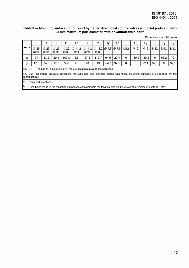
Table 8 — Mounting surface for four-port hydraulic directional control valves with pilot ports and with 25 mm maximum port diameter, with or without drain ports
Dimensions in millimetres
P A T B La X Y G1b G2
b F1 F2 F3 F4 F5 F6
Axis ∅ 25 max.
∅ 25 max.
∅ 25 max.
∅ 25 max.
∅ 11,2 max.
∅ 11,2 max.
∅ 11,2 max.
∅ 7,5 ∅ 7,5 M12 M12 M12 M12 M12 M12
x 77 53,2 29,4 100,8 5,6 17,5 112,7 94,5 29,4 0 130,2 130,2 0 53,2 77
y 17,5 74,6 17,5 74,6 46 73 19 − 4,8 92,1 0 0 92,1 92,1 0 92,1
NOTE 1 The use of this mounting will require caution relative to the port seals.
NOTE 2 Operating pressure limitations for subplates and manifold blocks with these mounting surfaces are specified by the
manufacturer.
a Drain port is optional.
b Blind holes made in the mounting surfaces to accommodate the locating pins on the valves; their minimum depth is 8 mm.
IS 10187 : 2013
ISO 4401 : 2005
13

Codification: 4401–10–09–0–05
Dimensions in millimetres
a The minimum thread depth is 1,5 cap screw (bolt) thread diameters, D. The recommended full thread depth shall be 2D + 6 mm to aid interchangeability of valves and to reduce the number of fixing cap screw (bolt) lengths. The
recommended engagement of fixing cap screw (bolt) threads for ferrous mountings is 1,25D. b The dimensions specifying the area within the dotted bold lines are the minimum dimensions for the mounting surface.
The corners of the rectangle may be radiused to a maximum radius, rmax, equal to the thread diameter of the fixing cap screws (bolts). Along each axis the fixing holes are at equal distances to the mounting surface edges.
c This dimension gives the minimum space required for a valve with this mounting surface. The dimension is also the minimum distance from centreline to centreline of two identical mounting surfaces placed on a manifold block. The
attention of valve manufacturers is drawn to the fact that no part of the width of the complete valve assembly is to exceed this dimension.
Figure 9 — Mounting surface for four-port hydraulic directional control valves with pilot ports and with 32 mm maximum port diameter, with or without drain ports
14
IS 10187 : 2013ISO 4401 : 2005

Table 9 — Mounting surface for four-port hydraulic directional control valves with pilot ports and with 32 mm maximum port diameter, with or without drain ports
Dimensions in millimetres
P A T B La X Y G1b G2
b F1 F2 F3 F4 F5 F6
Axis ∅ 32 max.
∅ 32 max.
∅ 32 max.
∅ 32 max.
∅ 11,2 max.
∅ 11,2 max.
∅ 11,2 max.
∅ 7,5 ∅ 7,5 M20 M20 M20 M20 M20 M20
x 114,3 82,5 41,3 147,6 0 41,3 168,3 138,6 41,3 0 190,5 190,5 0 76,2 114,3
y 35 123,8 35 123,8 79,4 130,2 44,5 0 158,8 0 0 158,8 158,8 0 158,8
NOTE Operating pressure limitations for subplates and manifold blocks with these mounting surfaces are specified by the
manufacturer.
a Drain port is optional.
b Blind holes made in the mounting surfaces to accommodate the locating pins on the valves; their minimum depth is 8 mm.
IS 10187 : 2013
ISO 4401 : 2005
15

Bibliography
[1] ISO 129, Technical drawings — Dimensioning — General principles, definitions, methods of execution and special indications
[2] ISO 286-1, ISO system of limits and fits — Part 1: Bases of tolerances, deviations and fits
[3] ISO 965-1, ISO general-purpose metric screw threads — Tolerances — Part 1: Principles and basic data
16
IS 10187 : 2013ISO 4401 : 2005

For the purpose of deciding whether a particular requirement of this standard is complied with, thefinal value, observed or calculated, expressing the result of a test or analysis, shall be rounded off inaccordance with IS 2 : 1960 ‘Rules for rounding off numerical values (revised)’. The number ofsignificant places retained in the rounded off value should be the same as that of the specified valuein this standard.
(Continued from second cover)

Bureau of Indian Standards
BIS is a statutory institution established under the Bureau of Indian Standards Act, 1986 to promote
harmonious development of the activities of standardization, marking and quality certification of goods
and attending to connected matters in the country.
Copyright
BIS has the copyright of all its publications. No part of these publications may be reproduced in any form
without the prior permission in writing of BIS. This does not preclude the free use, in course of imple-
menting the standard, of necessary details, such as symbols and sizes, type or grade designations.
Enquiries relating to copyright be addressed to the Director (Publications), BIS.
Review of Indian Standards
Amendments are issued to standards as the need arises on the basis of comments. Standards are also
reviewed periodically; a standard along with amendments is reaffirmed when such review indicates that
no changes are needed; if the review indicates that changes are needed, it is taken up for revision. Users
of Indian Standards should ascertain that they are in possession of the latest amendments or edition by
referring to the latest issue of ‘BIS Catalogue’ and ‘Standards: Monthly Additions’.
This Indian Standard has been developed from Doc No.: PGD 16 (1183).
Amendments Issued Since Publication______________________________________________________________________________________
Amendment No. Date of Issue Text Affected______________________________________________________________________________________
______________________________________________________________________________________
______________________________________________________________________________________
______________________________________________________________________________________
______________________________________________________________________________________
BUREAU OF INDIAN STANDARDSHeadquarters:
Manak Bhavan, 9 Bahadur Shah Zafar Marg, New Delhi 110002Telephones: 2323 0131, 2323 3375, 2323 9402 Website: www.bis.org.in
Regional Offices: Telephones
Central : Manak Bhavan, 9 Bahadur Shah Zafar Marg 2323 7617NEW DELHI 110002 2323 3841
Eastern : 1/14, C.I.T. Scheme VII M, V.I.P. Road, Kankurgachi 2337 8499, 2337 8561KOLKATA 700054 2337 8626, 2337 9120
Northern : SCO 335-336, Sector 34-A, CHANDIGARH 160022 260 3843260 9285
Southern : C.I.T. Campus, IV Cross Road, CHENNAI 600113 2254 1216, 2254 14422254 2519, 2254 2315
Western : Manakalaya, E9 MIDC, Marol, Andheri (East) 2832 9295, 2832 7858MUMBAI 400093 2832 7891, 2832 7892
Branches: AHMEDABAD. BANGALORE. BHOPAL. BHUBANESHWAR. COIMBATORE. DEHRADUN.FARIDABAD. GHAZIABAD. GUWAHATI. HYDERABAD. JAIPUR. KANPUR. LUCKNOW.NAGPUR. PARWANOO. PATNA. PUNE. RAJKOT. THIRUVANATHAPURAM. VISAKHAPATNAM.
Published by BIS, New Delhi
{{{
{{