IRP Auto Clutch Manual - Welcome to [Intuitive Race … 65 AutoClutch2009...IRP Auto Clutch Manual...
7
IRP Auto Clutch Manual KTM 65 SX 2009-2013 P/N 920400 10-12
Transcript of IRP Auto Clutch Manual - Welcome to [Intuitive Race … 65 AutoClutch2009...IRP Auto Clutch Manual...
IRP Auto Clutch Manual
KTM 65 SX 2009-2013
P/N 920400
10-12

Doth
insi
This maEnginee
The IRFully auManualCentrifuReducesAluminuHard co
17MM S8MM So4 MM A3 MM A10MM oFeelerScrewdCenterDremelTorque
Allow e
1. ShutAvoid w
2. Drain
3. PlaceNote:
ventilat
To
WARNING!!!not pump clutch lever when clutch cover is unbolted. The piston ine slave cylinder will over-travel and will break the snap ring area
de the housing of the slave cylinder. This is a very expensive repairthat must be prevented.
SEE PICTURE A
nual provides instructions for installing the IRP Auto Clutch into the 2009-2013 KTM 65 SXred for MX racing as well as Hare Scrambles and Trail Riding.
P Auto clutch featurestomatic … Bike can be started or stopped in gear without pulling in leveroverride feature for MX startsgal force cam action lever design for powerful lock up as engine revs increaseunwanted wheel hop during downshifting
m components made from 7075-T6 alloy for max strengthat anodized for greater wear resistance
ocketcket and 8MM box wrenchllen wrenchllen wrenchpen end wrench
gaugeriver and long nose plierspunch and ball peen hammer or automatic center punchGrinder with cut off wheelwrench or Impact Wrench
ngine to cool to ambient air temperature and put bike in 2nd gear.
off fuel petcock We advise having only a small amount of fuel in tank to avoid spills.orking in a closed environment when gas is present.
oil.
bike on bike lift if available or lay bike on side with clutch cover facing up.When bike is laid on side gas will leak from the carburetor. Work in area with goodion and no open flames or sparks.
Forward
ols Required
Removing factory KTM Clutch
1
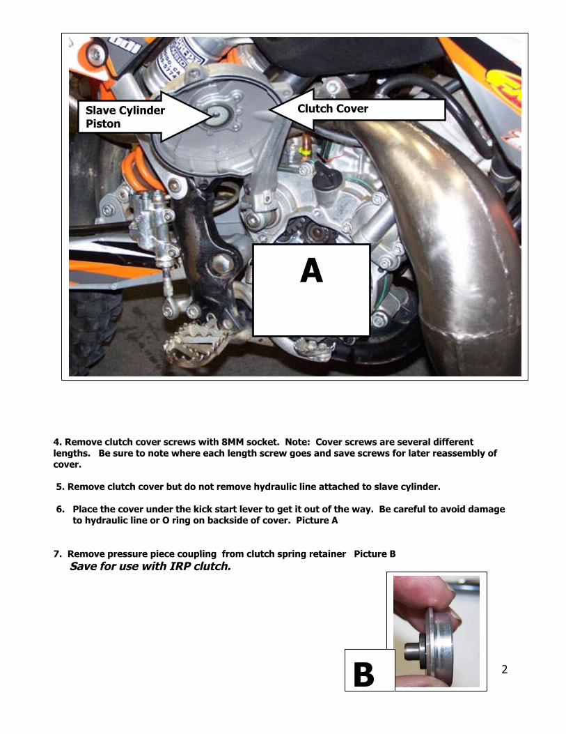
4. Remove clutch cover screws with 8MM socket. Note: Cover screws are several differentlengths. Be sure to note where each length screw goes and save screws for later reassembly ofcover.
5. Remove clutch cover but do not remove hydraulic line attached to slave cylinder.
6. Place the cover under the kick start lever to get it out of the way. Be careful to avoid damageto hydraulic line or O ring on backside of cover. Picture A
7. Remove pressure piece coupling from clutch spring retainer Picture B
Save for use with IRP clutch.
A
B
Slave CylinderPiston
Clutch Cover
2

8. Remove the KTM clutch. (Items 1-10)
9.
10pnS
11S
12aNmfrruP
Clean
. Grinlate caeededEE PIC
. LiftAVE GE
. Remnd SAVote: exust beom thbbers/N 47
oil from basket and gear.
d off top of rivets with Dremel until steeln be lifted off. Steel plate will not betherefore grinding into the plate in OK.TURE C
off gear from basket.AR FOR USE ON IRP BASKET
ove the rubber damping elementsE FOR USE ON IRP BASKET.cessively worn damping elementsreplaced. KTM rubber elements
e 85 SX are the same size as the 65 SXand are available from KTM032026000
REMOVING GEAR FROM KTM BASKET
C 3

13. Install 6 rubber damping elements on basket. PICTURE D
14. Install gear PICTURE E
15. Install IRP steel plate with spot face outward PICTURE F & H
16 . Apply 243 red loctite to special screws M6 and install in basket. Picture GInstall all screws before torque sequence. Tighten screws in a diagonal pattern. Torque to 11NMor 96 inch pounds. . Picture HWarning! These are special screws for clearance and use of any other type screw will causeclutch or engine damage17. Peen each screw from the inside of basket to prevent backing out. PICTURE I
INSTALLING GEAR ON IRP BASKET
D
FG
HI
E
4

18an
19
20plaTh
L
. Lever Support goes into basket with pocket outward … Picture J Note: levers are loose fitd may fall out if lever support is accidentally turned upside down !
. Place Pressure Plate into basket with pocket facing outward Picture K
. Apply grease to thrust washers and thrust bearing and place them into pocket in pressurete . Picture L The bearing goes between the washers Picture Me grease will help keep the washers and bearing in place when installing basket onto main shaft.
INSTALLING LEVER SUPPORT INTO BASKET
JK
Pressure Plate
Lever
install
M
5
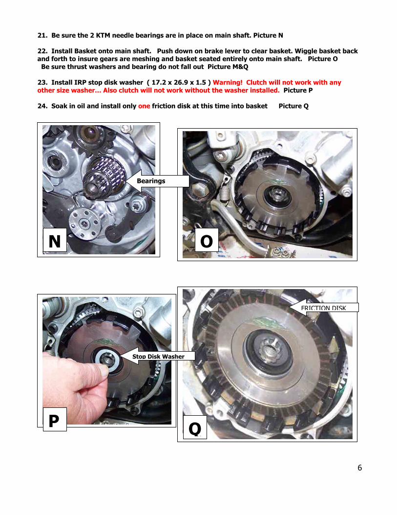
21. Be sure the 2 KTM needle bearings are in place on main shaft. Picture N
22. Install Basket onto main shaft. Push down on brake lever to clear basket. Wiggle basket backand forth to insure gears are meshing and basket seated entirely onto main shaft. Picture OBe sure thrust washers and bearing do not fall out Picture M&Q
23. Install IRP stop disk washer ( 17.2 x 26.9 x 1.5 ) Warning! Clutch will not work with anyother size washer… Also clutch will not work without the washer installed. Picture P
24. Soak in oil and install only one friction disk at this time into basket Picture Q
Bearings
N
Stop Disk Washer
P Q
O
FRICTION DISK
6