Iron Smelting with Non-Coking Coals in Low Shaft Furnace ...
13
Iron Smelting with Non-Coking Coals in Low Shaft Furnace 8 6 9 Iron Smelting with Non-Coking Coals in Low Shaft Furnace* A.B. CHATTERJEAand B.R. NIJHAWA N** In relation to classical reserves of high grade iron are in India, the reserves of good metallurgical grade of coking coals are extremely limited and that too confined to in the Bengal-Bihar belt. The development of small and medium scale iron and steel plants depends on the exploitation of sub-standard raw materials particularly the fuel unsuitable for con- ventional smelting in big blast furnaces of a million tonnes integrated iron and steel complex. The Low Shaft Furnace Pilot Plant installed at the National Metallurgical Laboratory, Jamshedpur(India) is designed to operate on sub-standard raw materials and non-metallurgical fuels for iron smelting. In 5•`6 years of extensive and painstaking trials, a great variety of raw materials have been investigated on a com- prehensive scale. It has been established that technological, operational and economic considerations preclude the adop- tion of a single stage process based on the smelting of single component burden of ore-fuel-limestone briquettes. The operational complexities and non-recovery of potential by-products have rendered the direct utilization of non-coking coals for iron smelting as lumpy bedded charge also impractical. The use of low temperature carbonized coke made from non- coking coals has enabled effective furnace operational control and uniformity of pig iron output of consistent composition. Carbon saturation of pig iron in initial trials was found to be low which depended on the basicity and MgO content of the slag. The effects of changes in the basicity of slag on carbon, silicon of pig iron, sulphur partition and on technical aspects of smelting, flux rate and fuel rate were investigated. The effects of particle size of raw materials and the rate of blowing, on top gas temperature, CO/CO2 ratio, fuel rate and dust loss were also comprehensively studied. Dolomite additions were found to improve the slag fluidity but somewhat adversely affected sulphur partition. It has been established that iron smelting in a low shaft blast furnace with low temperature carbonized coke can be successfully adopted in areas where coking coals reserves were limited. (Received 8 Aug. 1965) Introduction Conventional iron-making in the blast furnace depends on smelting lumpy or agglomerated iron o re burden employing hard metallurgical coke as the reductant and source of heat supply. Apart from direct reduction processes,1) iron smelting in a Low Shaft Furnace can well be undertaken with substandard fuels, such as non-coking coals2)•`4) low temperature coke carbonized from non- metallurgical coals, sub-size nut coke,2)5)•`8) lignite coke,9)•`12) anthracite etc. In India iron ores deposits are more or less uniformly dispersed. Scanty reserves of high grade metallurgical coking coals localized in Bengal-Bihar region of India, have given rise to intensive research and pilot plant investigations in the Low Shaft Furnace Pilot Plant of the National Metallurgical Laboratory at Jamshedpur, India; results of these investiga- tions based on sub-standard fuels and raw materials including iron are fines, were outlined in the In- ternational Symposium on "Iron and Steel making with Particular Reference to Indian Conditions"2) held in February, 1963. Further work on the subject since carried out and some of the results thereof have been discussed in this paper. The investigations were conducted in a Low Shaft Furnace of 1300mm hearth diameter, ef- fective height of 2.6m, useful volume of 7.3m3 provided with four tuyeres, details of which have been outlined earlier.2)3) Sections through shaft, hearth and the furnace profile are shown in Fig. 1. Chemical Analysis of Raw Materials Chemical composition of iron ores and fluxes collected from the different parts of India are given in Tables 1 and 2. The fusion points of the are were high. The proximate analyses of coking and non-coking coals, their caking index are given in Table 3. The analysis of coal ash is recorded in Table 4. The proximate analyses of nut-coke and low temperature carbonized coke made from wholly non-coking coals and their ash analyses are given in Tables 5 and 6. The non-coking coals are characterised by high volatile * 昭和40年4月 本会講演大会にて発表 昭和40年8月8日 受付 ** Dr . A.B. CHATTERJEA, Head, Low Shaft Furnace Project Division, National Metallurgical Labo- ratory and Dr. B.R. NITHAINAN, Director, National Metallurgical Laboratory, Jamshedpur (India). ― 4 5 ―
Transcript of Iron Smelting with Non-Coking Coals in Low Shaft Furnace ...

Iron Smelting with Non-Coking Coals in Low Shaft Furnace 8 6 9
Iron Smelting with Non-Coking Coals in Low Shaft Furnace*
A.B. CHATTERJEA and B.R. NIJHAWA N * *
In relation to classical reserves of high grade iron are in India, the reserves of good metallurgical grade of coking coals
are extremely limited and that too confined to in the Bengal-Bihar belt. The development of small and medium scale
iron and steel plants depends on the exploitation of sub-standard raw materials particularly the fuel unsuitable for con-
ventional smelting in big blast furnaces of a million tonnes integrated iron and steel complex. The Low Shaft Furnace
Pilot Plant installed at the National Metallurgical Laboratory, Jamshedpur(India) is designed to operate on sub-standard
raw materials and non-metallurgical fuels for iron smelting.
In 5•`6 years of extensive and painstaking trials, a great variety of raw materials have been investigated on a com-
prehensive scale. It has been established that technological, operational and economic considerations preclude the adop-
tion of a single stage process based on the smelting of single component burden of ore-fuel-limestone briquettes. The
operational complexities and non-recovery of potential by-products have rendered the direct utilization of non-coking coals
for iron smelting as lumpy bedded charge also impractical. The use of low temperature carbonized coke made from non-
coking coals has enabled effective furnace operational control and uniformity of pig iron output of consistent composition.
Carbon saturation of pig iron in initial trials was found to be low which depended on the basicity and MgO content
of the slag. The effects of changes in the basicity of slag on carbon, silicon of pig iron, sulphur partition and on technical
aspects of smelting, flux rate and fuel rate were investigated. The effects of particle size of raw materials and the rate
of blowing, on top gas temperature, CO/CO2 ratio, fuel rate and dust loss were also comprehensively studied. Dolomite
additions were found to improve the slag fluidity but somewhat adversely affected sulphur partition.
It has been established that iron smelting in a low shaft blast furnace with low temperature carbonized coke
can be successfully adopted in areas where coking coals reserves were limited.
(Received 8 Aug. 1965)
Introduction
Conventional iron-making in the blast furnace
depends on smelting lumpy or agglomerated iron
ore burden employing hard metallurgical coke
as the reductant and source of heat supply. Apart
from direct reduction processes,1) iron smelting
in a Low Shaft Furnace can well be undertaken
with substandard fuels, such as non-coking coals2)•`4)
low temperature coke carbonized from non-
metallurgical coals, sub-size nut coke,2)5)•`8) lignite
coke,9)•`12) anthracite etc. In India iron ores
deposits are more or less uniformly dispersed.
Scanty reserves of high grade metallurgical coking
coals localized in Bengal-Bihar region of India,
have given rise to intensive research and pilot
plant investigations in the Low Shaft Furnace
Pilot Plant of the National Metallurgical Laboratory
at Jamshedpur, India; results of these investiga-
tions based on sub-standard fuels and raw materials
including iron are fines, were outlined in the In-
ternational Symposium on "Iron and Steel making
with Particular Reference to Indian Conditions"2)
held in February, 1963. Further work on the
subject since carried out and some of the results
thereof have been discussed in this paper.
The investigations were conducted in a Low
Shaft Furnace of 1300mm hearth diameter, ef-
fective height of 2.6m, useful volume of 7.3m3
provided with four tuyeres, details of which have
been outlined earlier.2)3) Sections through shaft,
hearth and the furnace profile are shown in Fig. 1.
Chemical Analysis of Raw Materials
Chemical composition of iron ores and fluxes
collected from the different parts of India are
given in Tables 1 and 2. The fusion points ofthe are were high. The proximate analyses of
coking and non-coking coals, their caking index
are given in Table 3. The analysis of coal ash
is recorded in Table 4. The proximate analyses
of nut-coke and low temperature carbonized
coke made from wholly non-coking coals and their
ash analyses are given in Tables 5 and 6. The
non-coking coals are characterised by high volatile
* 昭和40年4月 本会講演大会にて発表
昭和40年8月8日 受付** Dr . A.B. CHATTERJEA, Head, Low Shaft Furnace
Project Division, National Metallurgical Labo-ratory and Dr. B.R. NITHAINAN, Director,National Metallurgical Laboratory, Jamshedpur(India).
― 4 5 ―

8 7 0 鉄 と 鋼 第 5 2 年 ( 1966 ) 第 5 号
Fig. 1. Section through shaft and hearth of the 15
tonnes/day low shaft furnace.
matter and high ash contents chiefly containingover 50% SiO2 and 25% Al2O3.
Smelting Trials
During the five to six years of extensive trials,
iron ores and fluxes from the various states ofIndia having widely different physical and chemical
characteristics were smelted with non-coking coalsand low-temperature carbonized coke made thereof
by non-conventional technique. The effects ofthe variation of the operational conditions like
particle size of iron are and limestone, the depthof the burden, blast temperature, pressure and
volume, basicity degree of the slag and dolomite
additions on the smelting characteristics were
determined.
The non-coking coals were utilized (i) by briquet-
ting with iron are fines and limestone, (ii) lumpy
form of burden and (iii) after carbonization at
low temperature with its conversion to soft coke.
Nut coke -35+12mm sub-standard in size
and unsuitable for iron-smelting in conventional
pig iron blast furnace was also extensively employed
in the Low Shaft Furnace Pilot Plant investiga-
tional trials.
In the lumpy form of burden, iron are fines
(70% below 6mm) was employed directly. The
slag basicity CaO/SiO2 of 1.0 to 1.2 was normally
aimed.
Smelting of Self Fluxing Briquettes
The raw materials (0 to 5mm) are briquetted
in roller briquetting machine with the addition
of 4% coal-tar pitch and 4% sulphite lye as binders.
The briquettes contained 18•`25% iron ore,
12•`19%, limestone and 59•`64% non-coking
coal. The flow sheet of the briquetting process
is shown in Fig. 2. The shape and size of a briquette
is shown in Fig. 3. The coking characteristics
of coal largely determined stability of the briquettes
within the furnace. As the briquettes were
subjected to progressively increasing load and
higher temperatures during their descend, the
room temperature crushing strength of the green
briquettes or after their carbonization at various
temperatures could not precisely indicate the
furnace stability. The variation of the crushing
strength, Shatter and abrasion indices with tem-
perature are recorded in Tables 7 to 9.
In general the strength of the briquettes increased
on carbonization. But in order to simulate smelt-
ing conditions the furnace stability was determined
by under load tests at progressively higher tempera-
tures. During smelting of a mixed burden consist-
ing of 50% briquettes and nut coke, the latter
improved the permeability of the burden column;
the disintegration however, of briquettes into
fine particles of dust constituted the most difficult
problem for their successful utilization for iron
smelting. The operational results with progres-
sive increasing quantities of briquettes in the
burden are recorded in Table 10. The fuel
consumption and the slag volume decreased with
increased amounts of briquettes in the burden.
During extensive trials exclusively with self-fluxing
― 4 6 ―

Iron Smelting with Non-Coking Coals in LDW Shaft Furnace 8 7 1
Fig. 2. Flow sheet of briquetting plant .
Fig. 3. Size and shape of briquettes.
briquettes, the wind rate was deliverately altered
by increasing the effective tuyere diameter from
60mm, through 75mm to 100mm in steps and
the results are summarised in Table 11. With
the increase in wind volume daily output increased
from 7 tonnes through 9 tonnes to 11.2 tonnes,
which altered the fixed carbon consumption per
unit hearth area per hour from 606 kg, through
846kg to 1081kg inclusive of dust loss, which
was about 10% of the burden. The top gas
CO/CO2 ratio, fuel rate and slag volume
increased at the higher rates of blowing.
Although intimate contact of the fine grained
constituents in the briquette was expected to
promote reduction and lower the fuel rate,
latter was higher compared to a burden
consisting of nut coke and optimum sized
lumpy iron ore, which was due distinctly
to the heat requirements for the carbonization
of coal present in the briquettes. The
amount and quality of coal-tar recovered
during the process of gas cleaning could not
be employed as binder for briquetting.
Apart from the impossibility of obtaining
briquettes of adequate furnace stability con-
taining besides other constituents non-coking
coals exclusively, the technological difficulties
of their smelting and the cost of binders
precluded the commercial adaptation of the
single stage one component burden process,3)4)
particularly under Indian climatic and
monsoon rainy conditions.
Non-coking coals-bedded form of burden:
As coals of reasonably high caking index will
form a sintered mass at the higher stack region
of the furnace and interfere with the smooth descend
of the burden, coals of poor caking index were
chosen. The particle size of the iron ores varied
from 35% to 95% below 12mm and for lime-
stones for 80 to 98% below -25mm. The
operational results are summarised in Table 12.
The direct utilization of high volatile (26•`40%)
― 4 7 ―

8 7 2 鉄 と 鋼 第 5 2 年 ( 1966 ) 第 5 号
Table 1. Composition of iron ores, %.
Table 2. Analyses of limestone and dolomite, %.
high ash (16•`24%) non-coking coals of very
low coking indices employed in bedded form of
burden although some what more successful than
briquettes cannot also be adapted on commercial
scale owing to poor permeability of the stock,
irregular descent of burden to non-uniform furnace
operations and wide fluctuations in composition
of the pig iron smelted.
Smelting with Low-Temperature
Carbonized Coke Made from
Non-Coking Coals
In view of technical drawbacks and highly
unfavourable economics of iron production under
commercial conditions by the direct utilization
Table 3. Proximate analyses, caking index of non-coking and coking coals.
― 4 8 ―
Iron Smelting with Non-Coking Coals in Low Shaft Furnace 8 7 3
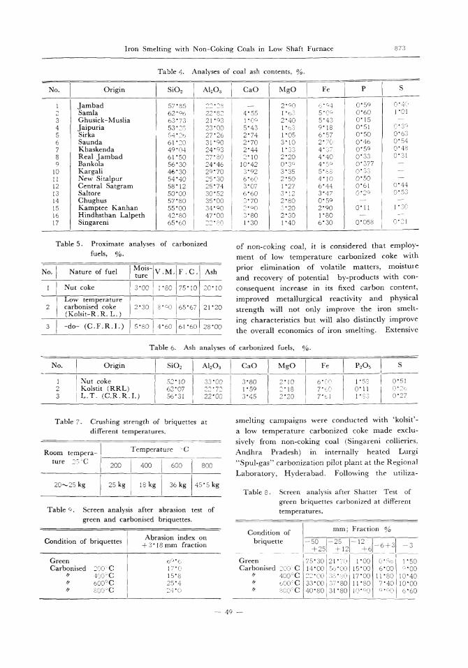
Table 4. Analyses of coal ash contents, %.
Table 5. Proximate analyses of carbonized
fuels, %.of non-coking coal, it is considered that employ-
ment of low temperature carbonized coke with
prior elimination of volatile matters, moistureand recovery of potential by-products with con-
consequent increase in its fixed carbon content,
improved metallurgical reactivity and physical
strength will not only improve the iron smelt-
ing characteristics but will also distinctly improve
the overall economics of iron smelting. Extensive
Table 6. Ash analyses of carbonized fuels, %•
Table 7. Crushing strength of briquettes at
different temperatures.
Table 9. Screen analysis after abrasion test of
green and carbonised briquettes.
smelting campaigns were conducted with 'kolsit'-a low temperature carbonized coke made exclu-sively from non-coking coal (Singareni collieries.
Andhra Pradesh) in internally heated Lurgi"Spul -gas" carbonization pilot plant at the Regional
Laboratory, Hyderabad. Following the utiliza-
Table 8. Screen analysis after Shatter Test of
green briquettes carbonized at differenttemperatures.
― 4 9 ―

8 7 4 鉄 と 鋼 第 5 2 年 ( 1966 ) 第 5 号
tion of 'kolsit's semlting trials were conducted
with another variety of low temperature carbonizedcoke made exclusively from non-coking coals
of Raniganj field by low temperature carboniza-tion in externally heated ovens at the Central
Fuel Research Institute, Dhanbad. The physical
properties of these soft cokes were inferior to me-tallurgical coke.
The smelting operations were conducted with alarge varieties of ores of different chemical and
physical characteristics and imposed conditions.The particle size of the raw materials is given in
Table 10. Operational conditions, analyses of pig
iron, slag and gas under progressively
increasing briquettes in the burden.
Table 13 and the operational data are summarised
in Table 14. The smelting with low temperature
carbonized coke made from totally non-coking
coals and containing 8•`10% volatile matter was
characterised by smooth descent of the burden
which fed adequately prepared burden to the smelt-
Table 11. Operational conditions, analyses of
products at different blowing rates.
Table 12. Operational characteristics with non-coking coals.
― 5 0 ―

Iron Smelting with Non-Coking Coals in Low Shaft Furnace 8 7 5
Table 13. Screen Analysis of raw-materials smel-
ted with low-temperature carbonized
coke, %.
Remarks:
a) As received.
b) After screening through-12mm screen.
c) After crushing and screening.
ing zone and thereby led to uniform furnace opera-tions and uniform analyses of pig iron casts.
A comparison of the fuel rate obtained with thetwo varieties of low temperature carbonized cokes
showed that the fuel rate with L.T.C. (C.F.R.I.)was higher than with Kolsit. Apart from difference
in their reactivities, the higher ash content of 28%in the L.T.C. (C.F.R.I.) resulted in higher slagvolume, whilst its larger particle size and higher
CO/CO2 ratio of the top gas accounted for the higher
fuel rate. The porus spongy structure with largenumber of fissures parallel to its banded structure,relatively poor resistance to crushing resulted in
its higher dust loss.
Smelting with Nut-coke
It has been well established that -35mm sub-
size nut coke is highly disadvantageous in big
Table 14. Operational characteristics with low-temperature carbonised coke.
Fig. 4. Particle size of ore, CO/CO2 ratio, fuel rate and slag-volume.
― 5 1 ―

8 7 6 鉄 と 鋼 第 5 2 年 ( 1966 ) 第 5 号
blast furnace operations.14) Its use reduces the
permeability of the burden column and its additionas fuel leads to false economy in conventional blastfurnace operations. The size grading of coke is
essential for increasing the productivity. In con-sideration of these aspects, the utilization of surplussub-size nut-coke of 12mm to 35mm size available
from the integrated iron and steel plants in smallblast furnace and low shaft furnace operations is
highly attractive from more than one angle. The
purposes for employing nut-coke in the Low ShaftFurnace Pilot Plant were (i) for ascertaining the
smelting characteristics at the initial stages, (iias corrective dose for regulating the smelting tria
operations (iii) as mixed fuel with either noncoking coals or self-fluxing briquettes and (ivfor smelting of raw materials from the regions pos
sessing no coal deposits. But due to the shorstack height of the furnace, adequate heat exchang
could not be attained, resulting in high top gatemperature. The effects of matching the fin
particle size of the burden constituents on loweringthe temperature of top gas vis-a-vis smelting char
acteristics were comprehensively investigated, and
Table 15. Operational characteristics with nut coke.
Table 16. Consolidated data on operation with Kolsit and fine-grained iron
re showing decrease of fuel rate with progress of smelting.
N.D.=Not determined.
― 5 2 ―

Iron Smelting with Non-Coking Coals in Low Shaft Furnace 877
the results are recorded in Table 15.
Study of Operational Variables
Fuel rate:
The higher CO/CO2 ratio in top gas indicated
that steep temperature gradient, small height of
the furnace shaft with consequent faster rate of
descent of the burden militated against maximum
gaseous indirect reduction in the Low Shaft Furnace
COHEUR8) accounted for 16% higher fuel rate due
to higher CO/CO2 ratio in the top gas of the In-
ternational Low Shaft Furnace. From the high
CO/CO2 ratio in the top gas of commercial low-
shaft furnaces at Calbe, East Germany STRUVE
and ERBERT15) indicated that the mean degree
of indirect reduction was 30% in comparison to
55•`60% in normal blast furnace, which was partly
responsible for high fuel rate. The only means
of improving the CO/CO2 ratio was therefore by
proper matching of the particle sizes of the burdening
materials. Fig. 4 shows the effects of the mean
particle size of the iron ore on the CO/CO2 ratio,
fuel rate, top gas temperature and slag volume.
The CO/CO2 ratio decreased from 6.4 to 5.4, with
consequent improvement in indirect reduction and
thereby decreased the fuel rate and slag volume
significantly. The lower top gas temperature
indicated better heat exchange and preparation
of the descending burden. The progressive re-
placement of lumpy limestone (50•`75mm) with
fine grained limestone (97% below-6mm) was
studied. While utilization of fine grained iron ore
was not instrumental in promoting excessive flue
dust lossed due to the coalescence of superficially
reduced iron particles, the finer particles of limestone
were carried into the flue dust and the basicity of
the slag thereby differed appreciably from the calcu-
lated values. However, the replacement of lumpy
limestone (50 to 75mm) progressively by 25%,
50%, 75% fine grained limestone (97%, below-6
mm) decreased the fuel rate by 10%, 19% and 30%;
increased the daily iron output by 29%, 40%
and 42% whilst increasing unfavourably the flue
dust losses by 8%, 40% and 62% respectively.
The decreased permeability and increased flue
dust losses, therefore, limited the use of fine grained
ore or particularly flux, beyond certain optimum
values. The data in Table 16, demonstrated that
constancy of the smelting operation over a long
period reduced the fuel rate significantly. Fig.
Fig. 5. Effect of hot blast temperature on
fuel rate.
Fig. 6. Influence of silicon contents on fuel rate.
Table 17. Effect of decreasing the basicity degree
of slag on smelting characteristics.
5 shows that the fuel rate itself was significantly
influenced by the hot blast temperature and Fig.
6 show that silicon contents of pig iron influenced
the fuel rate.
Smelting under different slag basicities:
The fuel rate in a Low Shaft Furnace is higher
than in a conventional big blast furnace primarily
due to the limited indirect reduction as indicated
―53―

878 鉄 と 鋼 第 52 年 (1966) 第 5 号
Fig. 7. Basicity ratio and carbon contents.
by the high CO/CO2 ratio. Strauve15) conductedinvestigations in low-shaft furnace with basicityratios CaO/SiO2 of 1.12 and 0.69 when theflux rate dropped from 916 to 870kg and coke ratedecreased from 1980 to 1627kg/tonne of pig iron.With the object of reducing the flux addition, slagvolume and consequently the fuel rate, the basicityvalues of the slag were maintained at 0.70, 0.87and 1.0 for extensive smelting trials the results are
given in Table 17.Fig. 7 shows that the somewhat poor carbon
saturation in the Low Shaft Furnace pig ironfurther deteriorated under acid smelting. Thesmelting characteristics were satisfactory up to aCaO/SiO2 ratio of 0.60, below which the slagbecame abnormally viscous. The flux and fuelrates substantially decreased on decreasing CaO/
Fig. 8. Basicity of slag and partition of sulphur.
SiO2 ratio, but the partition of sulphur
was adversely affected due to poor sulphur
capacity of acid slag, which will require
ladle desulphurisation of the pig iron for
foundry uses or for steel making.
Partition of sulphur between the
smelting products:
From the chemical analyses of the raw
materials employed for smelting, it is
apparent that most of the sulphur input
originated from the fuel. The higher fuel
rate in the low-shaft furnace will, there-
fore, increase the sulphur load and a higher
degree of desulphurisation will be required
to confine the sulphur content of pig iron
within the specified limits. Amongst the
other factors, the basicity degree of the slag andsilicon contents in pig iron chiefly affect the
sulphur partition. Fig. 8 illustrates the effect ofbasicity degree of the sulphur partition when pig
iron contained 2.5 to 3.5% Si. The swingstowards high sulphur contents in metal were
due to the irregularity of smelting operation. Asmooth and regular descent of the burden andlow FeO contents in the slag assured desulphuriza-
tion, as illustrated in Fig. 9. The low retentiontime in low shaft furnace adversely affects sulphur
partition. However, the average sulphur contentsof 0.07% under a comparatively low lime basicityratio of 1.10 was due to high silicon content of 2.5
to 3.5% of pig iron and large slag volume of 1.0tonnes/tonne of pig iron.
Fig. 9. FeO contents of slag and sulphur in
pig iron.
―54―

Iron Smelting with Non-Coking Coals in Low Shaft Furnace 8 7 9
Rate of blowing:
The fuel rate reached a minimum value at an op-
timum blowing rate. With a burden composed
of small lumpy iron ore, blended fluxes of limestone
and dolomite and low temperature carbonised coke,
effects of increase in blast volume and pressure on
the smelting efficiency were examined. On in-
creasing the blast pressure and volume, production
of pig iron naturally was increased. The increase
in blast volume by 8% and 12% over the base
period increased the production substantially
without any significant effects on the fuel rates.
Addition of dolomite to the burden:
High alumina in the slag increased its viscosity.
In order to improve the fluidity of the slag, the MgO
contents were varied from 9•`10%, 13•`15%
and 17•`19% in three stages maintaining the lime
basicity ratio between 1.15•`1.25. The presence
of a minimum of 7•`8%MgO in the slag considera-
bly improved its fluidity and MgO contents up to
15% did not adversely affect the smelting operation.
The influence of increasing the MgO content of
the slag was equally to improve the carbon satura-
tion in pig iron.
Future Programme of Investigation
In order to study the effect of injection of low
shaft furnace top gas of somewhat higher fuel
value than the conventional blast furnace gas, a
Shaft Furnace 8m high, 0.51m hearth diameter
was designed and fabricated at the National Metal-
lurgical Laboratory as shown in Photo. 1. The
furnace is provided with facilities for injecting gase-
ous fuels through a set of auxiliary tuyeres
placed at the same height as air blast tuyeres but
inclined to one another so that the gas stream and
air impinge at appropriate points inside the furnace
hearth. The four auxiliary tuyeres are placed
alternatively to 4 air blast tuyeres. The gas will
be injected under pressure and the air blast will
be enriched if so desired, with oxygen. In order
to recover the sensible heat content from the top
gas and eliminate the necessity of expensive blast
heating equipment arrangements have been pro-
vided for pre-heating the blast at the top of the
furnace by means of a recuperator arrangement.
An automatic skip hoist feeds the raw materials
to the furnace. Suitably located water spray
system cools the outer mild steel shell of the furnace
excepting the topmost part where the blast heat-
ing recuperator has been fitted.
Photo. 1. Shaft furnace with twin tuyeres.
Injection of Light Petroleum Naphtha
References to technical literature show thatliquid petroleum naphtha has not so far perhapsbeen used for direct injection into the hearth ofan iron blast furnace. The National MetallurgicalLaboratory, Jamshedpur, India will be pioneeringa research programme for the injection of liquid
petroleum product in its low-shaft furnace pilotplant. The investigation is aimed to utilize surplusnaphtha.
Naptha, a cyclic hydrocarbon with a carbonto hydrogen ratio of 5.3:1 is obtained during re-fining of crude oil. The heat value of naphthais 11,220 Kcal/kg in comparison with 10,2 2 7Kcal/kg for the furnace oil. Naphtha containsonly 0.5% sulphur as against 3.0% in furnace oil.Due to its high fluidity, no prior heating is necessaryand can be automized readily. But as it is muchmore volatile and inflamable, the installation ofthe injection system should have ample safetydevices and controls.
The injection system as shown in schematicdiagram in Fig. 10 consists of an underground stor-age tank of 12500 litres capacity provided withfitting arrangement vent hole and indicator.Naphtha in the tank is subjected to a pressure of
― 5 5 ―

880 鉄 と 鋼 第 52 年 (1966) 第 5 号
1kg/sq. cm. for its transfer
from the underground storage
tank to a 225 litres capacityservice tank installed above
the ground in the naphtha
pump room. The service tankhas also been provided witha relief valve so that the
pressure in excess of 1kg/sq.cm. can be automaticallyreleased. The service tank is
adequately equipped with pres-sure gauge and pressure swit-
ches. From the service tank,naphtha flows into two duplex
gear feed pumps coupledindividually to 1H.P. motorswith1440r.p.m. which areexpected to supply 100 litres
of light naphtha per hour ata pressure of 27kg/sq.cm.
The total amount of lightnaphtha passing through the 18mm pipe line is determined by
the flow indicator. The
pumps for the naphtha have Fig. 10. Schematic layout of fuel oil and light naphtha injection system.been housed in a separate room containing
no electrical circuit therein-the pumps are coupled
to the electric motors located in a separate room
with the shaft properly enclosed in asbestos packings.
The entire naphtha pipe line is welded and is laid
underground upto the control cubical in the control
room, where it is divided into four 6mm dia. pipes
each having a control valve and a pressure indicator
to control the rate of flow of naphtha through in-
dividual lances placed in the four tuyeres of the
Low Shaft Furnace. A three way air purging cock
has been provided to facilitate stoppage of naphtha
and its purging with compressed air. The lances
have been provided with a self closing coupling
to prevent possible ignition of naphtha in the supply
pipe line at the time of withdrawal of the naphtha
lances.
The naphtha injection lances as shown in Fig.
11 are made out of two concentric stainless steel
tubes, the inner tube will carry naphtha at a pressure
of 18kg/cm. sq. at the rate of 6•`12 litres per hour.
The space between the inner tube and ougter tube
is for passing compressed air at a pressure of 3
kg/cm. sq. which besides cooling the naphtha
Fig. 11. Naphtha lance assembly in tuyere.
lance, will admit the requisite amount of air forthe atomisation of naphtha through a suitable de-signed jet system. The naphtha is kept at high
pressure to prevent its vaporisation either in thelance or in the supply line.
The compressed air as cupplied by a compressor
―56―

Iron Smelting with Non-Coking Coals in Low Shaft Furnace 881
operated with a 7.5 H.P. motor having a capacityof 0.6m3/min. at a pressure of 13kg/sq. in. Itis provided with a 0.3m3 reservoir.
Necessary alarms have been provided in the systemto indicate failures due to the stoppage of circulationof naphtha in the lances, burning of the lances,choling of the lances, and failure of the compressedair lines.
Arrangements have been provided for injectionof furnace oil with simultaneous enrichment of theblast with oxygen.
Conclusions
On the basis of the extensive investigations ithas been concluded that low temperature carbonizedcoke made from non-coking coals and iron orefines can be employed for iron smelting in low shaftfurnace for the production of desired grades pigiron, at a fuel rate higher than the conventionalblast furnace.
Acknowledgements
The authors wish to thank Messrs Surinder SINGH,
J. GOSWAMI, S.K. BISWAS, R. Santok SINGH, J.S.PADAN, S.R. GHOSH, S.B. GHOSH, S.K.PALITand P.S. VIRDHI, Onkar SINGH and all the staffmembers of the Low Shaft Furnace Pilot PlantProject without whose help these extensive inves-tigations could not have been successfully con-ducted. The authors thanks are also due to theChemistry Division for anayltical work.
References
1) A.B. CHATTERJEA: Recent Trends in Iron Ore
Reduction Part I-Blast Furnace & Steel Plant,
U.S.A., May, 1964, p.397•`399 and Part II
June, (1964) p.488•`498
2) A.B. CHATTERJEA and B.R. NIJHAWAN: Iron
Production in Low Shaft Furnace Plant with
Indian Raw-materials (Preprint-International
Symposium on Recent Development in Iron &
Steel Making with Special Reference to Indian
Conditions, (1963), 1/42 to 1/64
3) H. REINFELD: Low Shaft Furnace Process (Iron
& Steel Trades Review, Nov. 9, 1956, p.1139•`
1148)
4) H. REINFELD: The Low Carbonization and Smel-
ting Process in Low-shaft Furnace (Symposium
on Pilot Plants in Metallurgical Research and
Development, NML-C. S. I. R., (1960), p.266
•`270)
5) H. MALCON: The International Low Shaft Fur-
nace-Five Years of Experimental Work at Oug-
ree (Iron and Coal Trades Rev., 177, Dec.
(1958), 1507)
6) H. MALCOR: Le Bas Fournean (Journees Inter-
nationales Siderurgie, Luxembourg, Belgique,
(1958), p.195•`213)
7) H. MALCOR: Experience with Low-shaft Furnace
at Ourgree (Symposium on Iron and Steel Ina-
ustry in India, NML-C.S.I.R., (1959, p.230
•`242)
8) P. COHEUR: Ore Fines utilized in Low-shaft
Furnace Process to Produce Thomas Pig Iron
(J. Metals, 17, (1955), 8, p.872•`876)
9) K. SAUBERLICH: Development of Low-shaft Fur-
nace Process in German Democratic Republic
(Neue Hutte, 1, (1950), p.193•`201)
10) H.J. Lux: Operation Experiences with Low
Shaft Furnace in the German Democratic Repu-
blic, Neue Hutte, Feb., (1956), p.216•`225
11) R. BAAKE: Structural Characteristics of Low-
shaft Furnaces in the D.D.T. (Neue Hutte,
Feb., (1956), p.203•`213)
12) K.F. LUDEMANN and G. von STRUVE: Metallur-
gical Processes in Low Shaft Furnace (Contem-
porary Problems in Metallurgy, Edited by A.
M. SAMARIN; Consultants Bureau, N.Y., (1960),
p.145•`157)
13) A.B. CHATTERJEA and B.R. NIJHAWAN: Low
Shaft Furnace Smelting on Iron and Steel
Industry in India-NML-CSIR (1959), p.244•`
251
14) E. BENSON: Institute of Fuel Symposium, (1959),
Paper C7
15) George von STRUVE, and Rolf ERBERT: Production
of Pig Iron in Low Shaft Furnace Plant at Calbe
in East Germany (Iron and Coal Trades Rev.,
Oct. 17, 1958)
16) G. von STRUVE: Acid Smelting of Foundry Pig
Iron in Low Shaft Furnace, J. Iron & Steel
Institute, (1960,) Sept. p.50•`55
― 57―