IRMWARE VERSION 040690 SET UP AND OPERATION
23
Spec Tech Design Manufacturing and Training F IRMWARE V ERSION 040690 S ET U P AND O PERATION 1
Transcript of IRMWARE VERSION 040690 SET UP AND OPERATION

Spec Tech
Design Manufacturing and Training
FIRMWARE VERSION 040690
SET UP AND OPERATION
1

2
Table of Contents
Overview
HMS & FCU Controls
Charging FCU’s
FCU LED Time Out
FCU Brightness
Mouse Wheel Emulation
Mounting HMS
IR Room Survey
Calibration Overview
GUI Screen Shot
Edge Calibration
3
6
9
10
11
12
13
14
15
16
17

POINT CTRLVIRTUAL REALITY CONTROL DEVICE SPEC TECH DESIGN MANUFACTURING AND TRAINING
HOW DOES POINT CTRL WORK
Point CTRL employs 3 wearable devices working in unison. The HMS sensor is mounted to the
Virtual Reality headset and tracks the position of each IR LED mounted to the FCU’s. The
location of the on-screen cursor in the virtual reality environment corresponds to where the user
is physically pointing in real life. Switches and dials are then manipulated by pressing the
function specific tactile switches on each FCU.
Prototype HMS and FCU
3

POINT CTRLVIRTUAL REALITY CONTROL DEVICE SPEC TECH DESIGN MANUFACTURING AND TRAINING
WHAT TECH DOES POINT CTRL USE
Point CTRL uses 3 wirelessly connected devices utilizing the newest IR optical tracking, and RF
transceiver technology.
FCU or the Finger Control Units consist of an Atmel MCU, 2.4GHZ transceiver, 850nm LED, three
tactile pushbuttons, and an 150mah onboard rechargeable lithium polymer battery.
HMS or the Head Mounted Sensor consist of a PixArt proprietary optical tracking sensor, 2/4GHZ
transceiver, Atmel MCU, two setup control buttons , and USB micro USB interface.
Point CTRL is recognized as a windows HID compliant pointing device, and requires no driver
installation. Point CTRL is compatible with any simulator, or software title that has mouse support.
4

POINT CTRLVIRTUAL REALITY CONTROL DEVICE SPEC TECH DESIGN MANUFACTURING AND TRAINING
COMPONETS
HMS ( Head Mounted Sensor)
FCU (Finger Control Unit)
3Meter Micro USB Cable
Lipo Battery Charger
Lipo Safe Bag
Attachment Accesories
5

POINT CTRLVIRTUAL REALITY CONTROL DEVICE SPEC TECH DESIGN MANUFACTURING AND TRAINING
HMS (HEAD MOUNTED SENSOR)
IR Sensor
BTN Right
Hold to Enter
User Settings
and
Calibration
Factory Reset
The HMS can be reset to
factory settings. Press and
hold both of the black
buttons on the HMS while
pressing and releasing the
white reset button. After
successful reset the cursor will
move from the left edge of
the field of view to the right
edge as confirmation.
Factory Calibration is for Rift S
, Full Screen, Stretched view,
but it will serv as a good
starting reference for all other
V/R Headsets.
HMS Reset
Double Press
for Firmware
Update
Micro USB
Connector
Auxiliary V/R HMD
Push-Button
Headers
BTN Left
Disables FCU
6

POINT CTRLVIRTUAL REALITY CONTROL DEVICE SPEC TECH DESIGN MANUFACTURING AND TRAINING
FCU (FINGER CONTROL UNIT)
IR LED
Charging
Jack
ON/OFF
Strap
Adjustment
Slots
Elastic
Strap
FCU Button 3
Mouse Wheel
FCU Button 2
Right Mouse BTN
FCU Button 1
Left Mouse BTN7
POINT CTRLVIRTUAL REALITY CONTROL DEVICE SPEC TECH DESIGN MANUFACTURING AND TRAINING
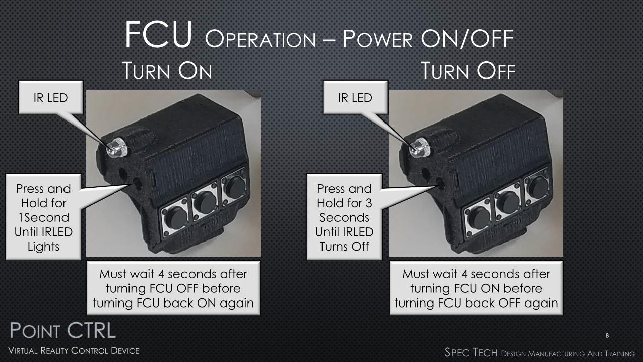
FCU OPERATION – POWER ON/OFF
TURN ON TURN OFF
IR LED
Press and
Hold for
1Second
Until IRLED
Lights
IR LED
Press and
Hold for 3
Seconds
Until IRLED
Turns Off
Must wait 4 seconds after
turning FCU OFF before
turning FCU back ON again
Must wait 4 seconds after
turning FCU ON before
turning FCU back OFF again
8

POINT CTRLVIRTUAL REALITY CONTROL DEVICE SPEC TECH DESIGN MANUFACTURING AND TRAINING
FCU CHARGING AND LIPO BATTERY SAFTEY
Black Case Intelligent ChargerNormal Charging time is between 15 and 40 minutes
9
LiPo Battery Safety
Care must be taken when
using Lithium polymer
batteries. A faulty charger or
battery could cause heat
and flames. Always store and
charge your FCU’s in the
provided fire-resistant case.
Never leave Lipo batteries
unattended during charging.
FCU Charger Red LED Status Indicator
FCU charger is plugged into 5v USB power source
All components in each kit before shipment, so the batteries may be fully charged.
Red Light ON Red Light OFF
Not Connected to FCU Connected to FCU Connected to FCU Fully Charged Charging
Graphic
Place Holder
Graphic
Place HolderGraphic
Place Holder

POINT CTRLVIRTUAL REALITY CONTROL DEVICE SPEC TECH DESIGN MANUFACTURING AND TRAINING
FCU OPERATION - LED TIME OUT
ENTER SET-UP MODE COUNT FLASHES
IR LED
Step (2)Press and Hold for
1 SecondIRLED will rapidly flash
for 1 second
confirming you are in LED Timeout mode
Step (3)IR LED Flashes
Once per second
Step (4)As soon as the desired time out is reached press FCU BTN 3 to save
Step(1) Press and Hold FCU BTN 1
before and while turning on FCU
Each Flash represents 10 seconds of LED TimeoutExample 4 flashes = 40
seconds of inactivity before the LED turns off.The LED is turned on by
pressing any of the three buttons
LED will flash rapidly and then turn off
confirming LED Time
Out is set. Press any BTN to turn on LED
10

POINT CTRLVIRTUAL REALITY CONTROL DEVICE SPEC TECH DESIGN MANUFACTURING AND TRAINING
FCU OPERATION - LED BRIGHTNESS ADJUSTMENT
ENTER SET-UP MODE SET BRIGHTNESS
IR LED
Step (2)Press and Hold until
IRLED lights up.IRLED will Slowly dim and then get bright
again, confirming you are in LED Brightness Adjustment Mode
Step (3)IR LED will display currently
set brightness
Step
(3A)Press to Brighten
LED
Step(1) Press and Hold FCU BTN 2
before and while turning on FCU
LED Brightness can be dimmed to save battery
life but is does slightly affect tracking resolution
Step
(3B)Press to Dim LED
Step (4)Press to
Save Brightness
setting
11

POINT CTRLVIRTUAL REALITY CONTROL DEVICE SPEC TECH DESIGN MANUFACTURING AND TRAINING
FCU OPERATION – MOUSE WHEEL FUNCTION
Press to Execute Mouse
Wheel Movement
Press to Set Mouse
Wheel Direction
Mode to Forward
Mouse Wheel Functionality Emulation Direction
The Mouse Wheel Button (3) will Emulate the Mouse
Movement Direction of the Last Pressed BTN (1 or 2)
Press to Set mouse
Wheel Direction
Mode to Backward
BTN 1BTN 2
Emulation Speed
The Mouse Wheel Speed will Start out Slowly and
Increase if the Execute BTN (3) is Held downBTN 3
Note:
When Changing Mouse Wheel
Direction with BTNs (1 or 2) be
sure to not click on switches or
dials
12

POINT CTRLVIRTUAL REALITY CONTROL DEVICE SPEC TECH DESIGN MANUFACTURING AND TRAINING
HMS OPERATION – MOUNTING TO VR HEAD SET
Pre-PositionCenter sensor and ensure it is parallel to your line of sight
before making contact with tape
Cut and Fit DS Tape Cut
and fit double sided tape
to HMS
Mount SensorFirmly Attach
Sensor and secure micro USB cable
with zip ties
13
Test Fit Generic MountIdentify Gaps to be filled with double
face tape or EVA foam if required
Dedicated
MountModel Specific
Dedicated Mounts require
no fitting. Example Rift S Support under the Micro USB
connector with the included zip tie mount to prevent board mount falure

POINT CTRLVIRTUAL REALITY CONTROL DEVICE SPEC TECH DESIGN MANUFACTURING AND TRAINING
HMS OPERATION – SURVEYING IR ENVIRONMENT / FCU TEST
Check Sensor FOVCheck Sensor Field of View By Moving FCU to Confirm LimitsNote: Default Cursor Target
Settings will have decreased FOV
HMS Power Indicator Red = ON
Survey RoomRotate Sensor
While Seated in
Flying Position to Check for Stray IR
Light Sources
Occlude Any Detected IR
Sources
IR and USB indicatorGreens or Red = IR Source
Detected within Set Cursor Limits
or Sending HID DATA
14
1 F
OV
141 F
OV
BADPhoto Courtesy
mariner3302
FCU In FOVRed or Green = FCU Visible
FCU Out Of FOVNo Light = FCU
Not Visible or Not
Currently Sending Data
14

POINT CTRLVIRTUAL REALITY CONTROL DEVICE SPEC TECH DESIGN MANUFACTURING AND TRAINING
CALIBRATION OVERVIEW
Set the Left and Right Cursor Targets at the Edge of Your V/R Head Set FOV
Each V/R Head has different resolutions and field of view. We must first define the Left and Right cursor
limits in V/R using the FCUs.
1
Calibrate FCU to Each Cursor TargetNext, we point at a single cockpit
control. Without moving our hand at any time, we rotate our head to move
the cursor to the control we are pointing at. We accept and continue
to rotate our head to align each target with the control we are pointing at.
1 32
4
This page is only an overview, Please use the GUI/Voice Assist for detailed instructions and procedures
15
Define the Upper and Lower Visible Cursor Targets for Your V/R Head Set
This step is not usually required. It is only necessary for desktops that are extended vertically by multiple
monitors or a V/R Headset reporting as two monitors.
5
Point at a single item in
the center for all 5
cursor targets

16
Screen Shot From GUI/Voice Assist

POINT CTRLVIRTUAL REALITY CONTROL DEVICE
EDGE CALIBRATION ADVANCED AND NOT REQUIRED
Edge Calibration is just what the name implies. We are
only adjusting the Finger to Cursor alignment at the
edges of our view without effecting the center
alignment.
The left and right Finger to Cursor Alignment is done in
one step because of the symmetrical bio-mechanics
between the FCU finger and the HMS.
(left and right edge movement is mirrored)
The upper and lower edges are adjusted separately
because of the asymmetric biomechanics of raising and
lowering the arms in relation to the FCU finger and the
HMS.
(up and down movement is not the same)
When properly executed, edge calibration will enable
the cursor to stay in the same location in the cockpit
when the head is slowly moved left, right, up, or down,
while the finger or FCU is stationary.
Note: While PointCTRL processes and sends mouse
commands at 200 FPS there is a short lag in V/R when
the head is moved quickly . This is followed by the
cursors quickly settling back down to its intended
position. (Looking into WMR implementation for solution)
Step 2Navigate to the Edge Calibration Mode
(4 Cursor Starburst)and Press FCU Button 3
V/R Head Set View
Menu Left
Displays Next
Graphic Menu Item
Menu Right
Displays Next
Graphic Menu Item
Select
Enters the Menu
Setting Item
Step 1Enter User Settings Menu
While in Cockpit ViewPress and Hold BTN2 (Right) for 3 seconds
17
HMS ON/OFF
Toggle
Do not press

POINT CTRLVIRTUAL REALITY CONTROL DEVICE
EDGE CALIBRATION LEFT AND RIGHT EDGE
Step 3Select a point in the cockpit where you will be manipulating most of your controls and center
it in your field of view and point at it. Finger and Cursor should line up
Step 4While keeping your hand in the same location,
move your head slowly left or right until the cursor reaches the edge of your view. Observe
if the cursor has moved left or right from its original location.
Move Cursor Left
Move Cursor Right
Advance to Next Step
Upper Edge Cursor Alignment18
Step 5Keeping your head and hand in the
same stationary position, adjust the lateral cursor location with the FCU buttons until it returns to its original
location centered on the MFD . Press FCU button 3 when done.
If cursor moved here
as head was rotated…
…with out moving you head or
hand ,move cursor back here
by pressing FCU Button 2
Center MFD in FOV
and Point at it

POINT CTRLVIRTUAL REALITY CONTROL DEVICE
EDGE CALIBRATION UPPER EDGE CURSOR
Step 6Return to your reference point in the cockpit
and center it in your field. Now point directly at the reference point again.
Finger and Cursor should line up
Step 7While keeping your hand in the same location, move your head slowly down until the cursor
reaches it movement limit. Observe if the cursor moves Above or Below original location.
Move Upper Cursor Up
Move Upper Cursor Down
Advance to Next Step
Lower Cursor Edge Alignment19
Step 8While keeping your head and hand in
the same stationary position, adjust the cursor location with the FCU
buttons until it returns to its original location centered on the MFD.Press FCU button 3 when done.
If cursor moved here as
head was rotated down…
…with out moving you head or
hand ,move cursor back here
by pressing FCU Button 2
Center MFD in FOV
and Point at it
Note:
During this phase you can
only adjust the cursors upper
limit. The FCU buttons will
only move the cursor when
the cursor is located on the
upper half of the screen.

POINT CTRLVIRTUAL REALITY CONTROL DEVICE
EDGE CALIBRATION LOWER EDGE CURSOR
Step 9Return to your reference point in the cockpit
and center it in your field. Now point directly at the reference point.
Finger and Cursor should line up
Step 10While keeping your hand in the same location, move your head slowly upward until the cursor
reaches it limit. Observe if the cursor moved Above or Below original location.
Move Upper Cursor Up
Move Upper Cursor Down
Advance to Save Settings
20
Note1:
During this phase you can
only adjust the cursors lower
limit. The FCU buttons will
only move the cursor when
the cursor is located on the
lower half of the screen.
Step 11While keeping your head and hand in
the same stationary position, adjust the cursor location with the FCU
buttons until it returns to its original location centered on the MFD.
Press FCU button 3 to save and Exit.
If cursor moved here when
you looked down…
…with out moving you head or
hand ,move cursor back here
by pressing FCU Button 2
Center MFD in FOV
and Point at it
Note 2:
Care must be take to
remember wich of the 3
cursor adjustment you are
making, 1) Left/Rigtht,
2)Upper, or 3) Lower.

USER SETTINGS FCU ZOOM
Step 2Navigate to the Zoom Mode (cursor tracing a
rectangle)and Press FCU Button 3
Step 3Two cursors , a center for reference, and the active, will
become visible. Move FCU to where you want the
Zoom to become active and Press FCU Button 2.
To Disable Proximity Zoom move the FCU close to HMS
while keeping the active cursor centered., When the
second cursor disappears Press FCU Button 2
V/R Head Set View
Menu Left
Displays Next
Graphic Menu Item
Menu Right
Displays Next
Graphic Menu Item
Select
Enters the Menu
Setting Item
Set Zoom Out Distance
Set Zoom In Distance
Save Setting and Exit
Step 1Enter User Settings Menu
While in Cockpit View
Press and Hold BTN2 (Right)
for 3 seconds
21
Step 4Move FCU to the distance where you want the Zoom
to Return to normal and FCU Button 1
Step 5Continue to test and modify you distance settings.
When satisfied Press FCU Button 3 to Save and Exit
2 & 3 Together
Zoom Out
1 & 2 Together
Zoom In
IRLED Not in
FOV Zoom Out
NoteIf Proximity Zoom is disabled, you will see the cursor
move from left to right before moving up when you
save the settings
ImportantIn DCS, you must first bind
the VR zoom to [RightALT]+[0]
[0] = Keyboard Zero, Not Pad

POINT CTRLVIRTUAL REALITY CONTROL DEVICE
Spec Tech
Design Manufacturing and Training
22

23
PointCTRL Sensor Field of View
VR Headset Image Field of View
Long armed Person
pointing at cursor
Short Armed Person
pointing at cursor
Cursor 45 degrees
right of center view
Cursor 45 degrees
left of center view
HMS sensor reading 60
degrees left of center
HMS sensor reading 50
degrees right of center
The reason we do not see a moving cursor while clicking on the cursor
target is because we want to point at the cursor targets naturally and
intuitively. This method aligns the cursors to our perception and feel of
where we are pointing in the 3d environment.