IRJET-Design and Analysis of High Pressure Ball Valve Sealing Cup with Different Sealing Materials
4
International Research Journal of Engineering and Technology (IRJET) e-ISSN: 2395 -0056 Volume: 02 Issue: 04 | July-2015 www.irjet.net p-ISSN: 2395-0072 © 2015, IRJET ISO 9001:2008 Certified Journal Page 1894 Design and Analysis of High Pressure Ball Valve Sealing Cup with Different Sealing Materials Prof. Sanjeev. A. Janawade 1 , Mr. Venukumar R Bankapur 2 1 Professor Design Engineering, Department of Mechanical Engineering, KLE Dr. MSSCET Belgaum, Karnataka, India 2 M.tech student of Design Engineering, Department of Mechanical Engineering, KLE Dr. MSSCET Belgaum, Karnataka, India ---------------------------------------------------------------------***--------------------------------------------------------------------- Abstract - A valve is a mechanical device which regulates either the flow or the pressure of the fluid. Among the different type of valves, high pressure ball valve finds use in certain applications like industrial hydraulics, mobile hydraulics and marine hydraulics. The present study involves designing the high pressure ball valve to the need of customer requirement. Ball valves, as the name implies, are stop valves that uses a ball to stop or start the flow of fluid. When the valve is handle is operated to open the valve, the ball rotates to a point where the hole through the ball is in line with the valve body inlet and outlet. When the valve is shut, which requires only a 90 degree rotation of the hand wheel for most valves, the ball is rotated so the hole is perpendicular to the flow opening of the valve body, and flow is stopped. Generally ball valves used have operational pressure range 10 bar to 1000 bar. When the flow line pressure exceeds 150 bar, the valves are known as high pressure valves. With the increasing pressure, the design of the various components of the valve becomes critical. The design of high pressure valve components depends on the pressure, temperature ratings and also on other factors. The design calculation is done for sealing cup. The maximum stress and deflection is calculated for different sealing cup materials for a test pressure. Sealing cup is modeled using catia modeling software and analyzed by use of Ansys software for test pressure. The analyses are done for different sealing cup materials (Polytetrafluoroethylene, Derlin-100 and Acetal) with different element sizes. Key Words: Ball valve, sealing cup, stress analysis. 1. INTRODUCTION A valve is a mechanical device which regulates either the flow or the pressure of the fluid. Its function can be stopping or starting the flow, controlling flow rate, diverting flow, preventing back flow, controlling pressure, or relieving pressure. 1.1 Classification of Valves Paragraph valves are classified by following methods. 1.1.1 Types of Operation 1. Manual 2. Solenoid 3. Hydraulic/pneumatic 1.1.2 The Nature and Physical Condition of the Flow 1. Low/High temperatures. 2. Low/high pressures. 3. Cavitations risk. 4. Corrosive or erosive properties of the flow. 5. Viscosity: Gas, Liquid and Solid. 6. Hygiene requirement (for the food or pharmacy industry). 7. Explosion and risk of inflammability (chemical, petrochemical industry). 1.1.3 Other Forms of Valve Classification 1. Admissible leakage level. 2. Connection to the pipe. 3. A unique direction of the flow or bidirectional flow. 4. Number of ports: most of the valves have two port, named inlet and outlet port. But for the applications there are multi-port configured valves. They can be three-way and four-way valves. 5. Angle between the inlet and outlet port of the valves. 1.1.4 Functionality 1. On/off valve service. 2. Positioning to % open.
description
A valve is a mechanical device which regulates either the flow or the pressure of the fluid. Among the different type of valves, high pressure ball valve finds use in certain applications like industrial hydraulics, mobile hydraulics and marine hydraulics. The present study involves designing the high pressure ball valve to the need of customer requirement. Ball valves, as the name implies, are stop valves that uses a ball to stop or start the flow of fluid. When the valve is handle is operated to open the valve, the ball rotates to a point where the hole through the ball is in line with the valve body inlet and outlet. When the valve is shut, which requires only a 90 degree rotation of the hand wheel for most valves, the ball is rotated so the hole is perpendicular to the flow opening of the valve body, and flow is stopped. Generally ball valves used have operational pressure range 10 bar to 1000 bar. When the flow line pressure exceeds 150 bar, the valves are known as high pressure valves. With the increasing pressure, the design of the various components of the valve becomes critical. The design of high pressure valve components depends on the pressure, temperature ratings and also on other factors. The design calculation is done for sealing cup. The maximum stress and deflection is calculated for different sealing cup materials for a test pressure. Sealing cup is modeled using catia modeling software and analyzed by use of Ansys software for test pressure. The analyses are done for different sealing cup materials (Polytetrafluoroethylene, Derlin-100 and Acetal) with different element sizes.
Transcript of IRJET-Design and Analysis of High Pressure Ball Valve Sealing Cup with Different Sealing Materials

International Research Journal of Engineering and Technology (IRJET) e-ISSN: 2395 -0056
Volume: 02 Issue: 04 | July-2015 www.irjet.net p-ISSN: 2395-0072
© 2015, IRJET ISO 9001:2008 Certified Journal Page 1894
Design and Analysis of High Pressure Ball Valve Sealing Cup with
Different Sealing Materials
Prof. Sanjeev. A. Janawade 1, Mr. Venukumar R Bankapur2
1 Professor Design Engineering, Department of Mechanical Engineering, KLE Dr. MSSCET Belgaum, Karnataka, India
2 M.tech student of Design Engineering, Department of Mechanical Engineering, KLE Dr. MSSCET Belgaum, Karnataka, India
---------------------------------------------------------------------***---------------------------------------------------------------------Abstract - A valve is a mechanical device which
regulates either the flow or the pressure of the fluid.
Among the different type of valves, high pressure ball
valve finds use in certain applications like industrial
hydraulics, mobile hydraulics and marine hydraulics.
The present study involves designing the high pressure
ball valve to the need of customer requirement.
Ball valves, as the name implies, are stop valves that
uses a ball to stop or start the flow of fluid. When the
valve is handle is operated to open the valve, the ball
rotates to a point where the hole through the ball is in
line with the valve body inlet and outlet. When the valve
is shut, which requires only a 90 degree rotation of the
hand wheel for most valves, the ball is rotated so the
hole is perpendicular to the flow opening of the valve
body, and flow is stopped.
Generally ball valves used have operational pressure
range 10 bar to 1000 bar. When the flow line pressure
exceeds 150 bar, the valves are known as high pressure
valves. With the increasing pressure, the design of the
various components of the valve becomes critical. The
design of high pressure valve components depends on
the pressure, temperature ratings and also on other
factors.
The design calculation is done for sealing cup. The
maximum stress and deflection is calculated for
different sealing cup materials for a test pressure.
Sealing cup is modeled using catia modeling software
and analyzed by use of Ansys software for test pressure.
The analyses are done for different sealing cup
materials (Polytetrafluoroethylene, Derlin-100 and
Acetal) with different element sizes.
Key Words: Ball valve, sealing cup, stress analysis.
1. INTRODUCTION A valve is a mechanical device which regulates either the flow or the pressure of the fluid. Its function can be stopping or starting the flow, controlling flow rate, diverting flow, preventing back flow, controlling pressure, or relieving pressure.
1.1 Classification of Valves Paragraph valves are classified by following methods.
1.1.1 Types of Operation 1. Manual 2. Solenoid 3. Hydraulic/pneumatic
1.1.2 The Nature and Physical Condition of the Flow
1. Low/High temperatures. 2. Low/high pressures. 3. Cavitations risk. 4. Corrosive or erosive properties of the flow. 5. Viscosity: Gas, Liquid and Solid. 6. Hygiene requirement (for the food or pharmacy
industry). 7. Explosion and risk of inflammability (chemical,
petrochemical industry).
1.1.3 Other Forms of Valve Classification 1. Admissible leakage level. 2. Connection to the pipe. 3. A unique direction of the flow or bidirectional
flow. 4. Number of ports: most of the valves have two
port, named inlet and outlet port. But for the applications there are multi-port configured valves. They can be three-way and four-way valves.
5. Angle between the inlet and outlet port of the valves.
1.1.4 Functionality 1. On/off valve service. 2. Positioning to % open.
International Research Journal of Engineering and Technology (IRJET) e-ISSN: 2395 -0056
Volume: 02 Issue: 04 | July-2015 www.irjet.net p-ISSN: 2395-0072
© 2015, IRJET ISO 9001:2008 Certified Journal Page 1895
3. Modulating to control changes on flow conditions. 4. Emergency shut down.
2. THEOROTICAL CALCULATION OF SEALING CUP Sealing cups are the one of the important component of the valve. The design of sealing cup will be based on the selection of sealing material and its properties. The following sealing materials are analyzed for the compressive strength and they are PTFE, Delrin-100 and Acetal. Design of sealing cups will be based on the compressive strength of the material, which sustains the required pressure.
2.1 Polytetrafluoroethylene (PTFE) Initially considering the sealing cups material will be PTFE. Sealing cups bore size d=25 mm Design pressure P=52.5 MPa
Assuming factor of safety F.O.S=2.5 Compressive strength of material Sc=41.40 MPa Force acting on the sealing cup, F=25,775 N Mean circumference of sealing cup, b=π*d Where, d=mean diameter of sealing cup Mean radius=14.5 mm Mean diameter d=29 mm b=92 mm Arc length, l=r*v l=5.5 mm Crushing area can calculated as, Ac=b*l Ac=506 mm2
Crushing strength or compressive strength on sealing cups is given by,
=51 MPa
Factor of safety F.O.S=
F.O.S=0.8 Since the F.O.S=0.8 for PTFE material, thus it cannot be used for high pressure valves. Deflection in sealing cup
F=Force acting on sealing cup is 25775 N L=Thickness of the sealing cup is 7 mm A=Cross section area of sealing cup
A=921.20 mm2
E=Modulus of elasticity of PTFE is 1400 MPa =0.14 mm
Thus by use of PTFE material, the deflection is 0.14 mm.
2.2 Delrin-100
Sealing cups material Delrin-100 Compressive strength of material Sc=96.50 MPa
F.O.S=1.90 Since the F.O.S=1.90 for Delrin-100 material, thus it cannot be used for high pressure valves. F=Force acting on sealing cup is 25775 N L=Thickness of the sealing cup is 7 mm A=Cross section area of sealing cup is 921.20 mm2
E=Modulus of elasticity of Delrin-100 is 2480 MPa
=0.08 mm Thus by use of Delrin-100 material, the deflection is 0.08 mm.
2.3 Acetal (Poly Oxy Methylene) Sealing cups material Delrin-100 Compressive strength of material Sc=124.10 MPa
F.O.S=2.45 Since the F.O.S=2.50 for Acetal materials, thus it can be used for high pressure valves. F=Force acting on sealing cup is 25775 N L=Thickness of the sealing cup is 7 mm A=Cross section area of sealing cup is 921.20 mm2
E=Modulus of elasticity of Acetal is 3400 MPa
=0.06 mm Thus by use of Acetal material, the deflection is 0.06 mm.
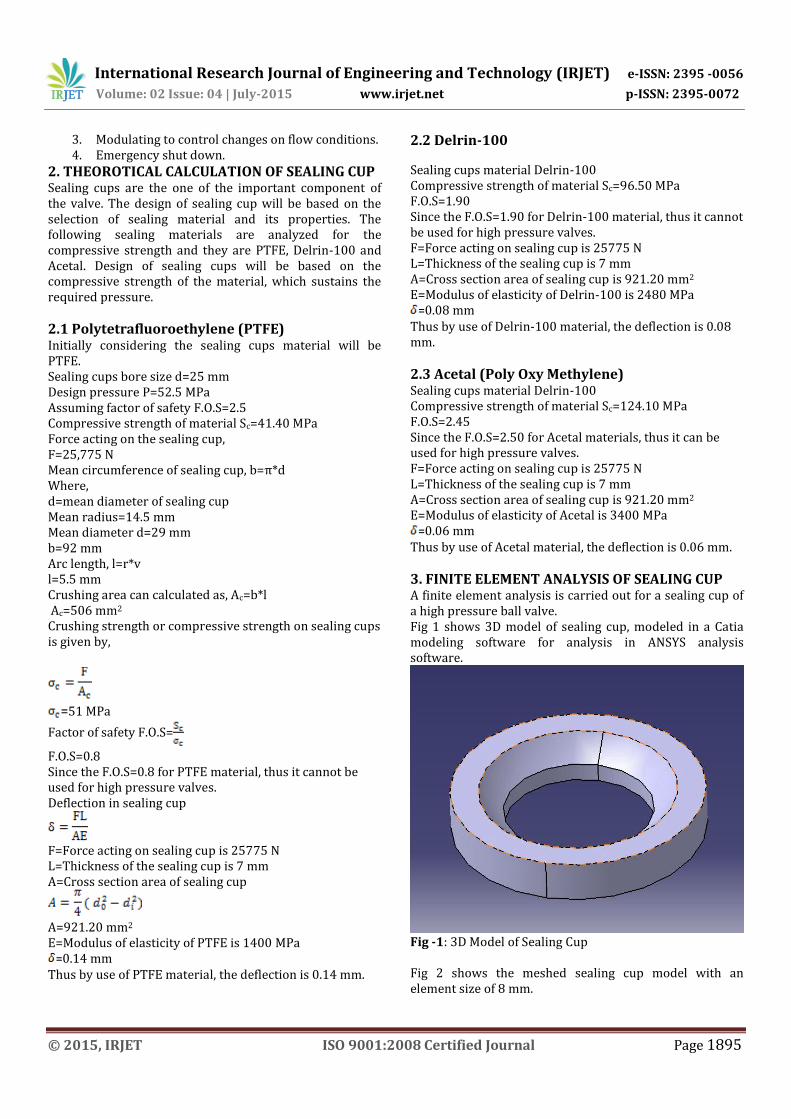
3. FINITE ELEMENT ANALYSIS OF SEALING CUP A finite element analysis is carried out for a sealing cup of a high pressure ball valve. Fig 1 shows 3D model of sealing cup, modeled in a Catia modeling software for analysis in ANSYS analysis software.
Fig -1: 3D Model of Sealing Cup Fig 2 shows the meshed sealing cup model with an element size of 8 mm.

International Research Journal of Engineering and Technology (IRJET) e-ISSN: 2395 -0056
Volume: 02 Issue: 04 | July-2015 www.irjet.net p-ISSN: 2395-0072
© 2015, IRJET ISO 9001:2008 Certified Journal Page 1896
Fig -2: Meshed Sealing Cup Model Fig 3 shows applying load and boundary condition to the sealing cup model, the applied load is 52.5 MPa.
Fig -3: Applying Load and Boundary Condition to the Sealing Cup Model
3.1 Analysis of Polytetrafluoroethylene Sealing Cup The model is analyzed for a pressure of P=52.5 MPa is applied at the curved portion of the sealing cup. A model meshed 8 mm element size has 369 numbers of nodes and 153 numbers of elements. Fig 4 shows the stress distribution of Polytetrafluoroethylene sealing cup, it has maximum stress of 54.09 MPa and minimum stress of 12.07 MPa. Fig 5 shows the deformation of PTFE sealing cup with maximum deformation of 0.31 mm and minimum deformation of 0 mm.
Fig -4: Stress Distribution of Polytetrafluoroethylene Sealing Cup
Fig -5: Deformation of Polytetrafluoroethylene Sealing Cup Table 1 shows stress and deformation results of PTFE sealing cup with varying element size. Table -1: Results of PTFE Sealing Cup Stress
(MPa) Deformation (mm)
Max Min Max Min Element size of 8 mm
54.09 12.07 0.31 0
Element size of 6 mm
54.96 13.80 0.29 0
Element size of 4 mm
54.03 12.30 0.29 0
Element size of 2 mm
68.11 6.56 0.29 0
3.2 Analysis of Delrin-100 Sealing Cup The model is analyzed for a pressure of P=52.5 MPa is applied at the curved portion of the sealing cup. A model meshed 8 mm element size has 369 numbers of nodes and 153 numbers of elements. Fig 6 shows the stress distribution of Delrin-100 sealing cup, it has maximum stress of 55.19 MPa and minimum stress of 14.01 MPa. Fig 7 shows the deformation of PTFE sealing cup with maximum deformation of 0.13 mm and minimum deformation of 0 mm.
Fig -6: Stress Distribution of Delrin-100 Sealing Cup
Fig -7: Deformation of Delrin-100 Sealing Cup Table 2 shows stress and deformation results of Delrin-100 sealing cup with varying element size.
International Research Journal of Engineering and Technology (IRJET) e-ISSN: 2395 -0056
Volume: 02 Issue: 04 | July-2015 www.irjet.net p-ISSN: 2395-0072
© 2015, IRJET ISO 9001:2008 Certified Journal Page 1897
Table -2: Results of Delrin-100 Sealing Cup Stress
(MPa) Deformation (mm)
Max Min Max Min Element size of 8 mm
55.9 14.01 0.13 0
Element size of 6 mm
56.97 12.21 0.12 0
Element size of 4 mm
55.81 11.44 0.12 0
Element size of 2 mm
66.51 3.98 0.12 0
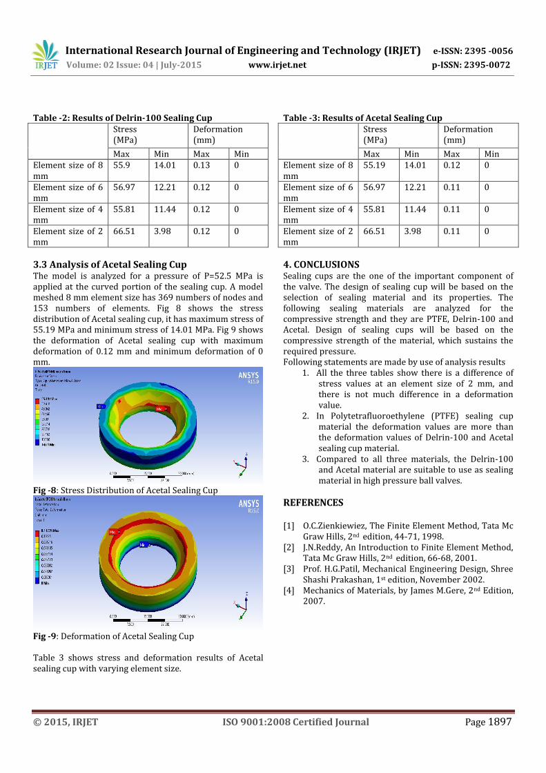
3.3 Analysis of Acetal Sealing Cup The model is analyzed for a pressure of P=52.5 MPa is applied at the curved portion of the sealing cup. A model meshed 8 mm element size has 369 numbers of nodes and 153 numbers of elements. Fig 8 shows the stress distribution of Acetal sealing cup, it has maximum stress of 55.19 MPa and minimum stress of 14.01 MPa. Fig 9 shows the deformation of Acetal sealing cup with maximum deformation of 0.12 mm and minimum deformation of 0 mm.
Fig -8: Stress Distribution of Acetal Sealing Cup
Fig -9: Deformation of Acetal Sealing Cup Table 3 shows stress and deformation results of Acetal sealing cup with varying element size.
Table -3: Results of Acetal Sealing Cup Stress
(MPa) Deformation (mm)
Max Min Max Min Element size of 8 mm
55.19 14.01 0.12 0
Element size of 6 mm
56.97 12.21 0.11 0
Element size of 4 mm
55.81 11.44 0.11 0
Element size of 2 mm
66.51 3.98 0.11 0
4. CONCLUSIONS Sealing cups are the one of the important component of the valve. The design of sealing cup will be based on the selection of sealing material and its properties. The following sealing materials are analyzed for the compressive strength and they are PTFE, Delrin-100 and Acetal. Design of sealing cups will be based on the compressive strength of the material, which sustains the required pressure. Following statements are made by use of analysis results
1. All the three tables show there is a difference of stress values at an element size of 2 mm, and there is not much difference in a deformation value.
2. In Polytetrafluoroethylene (PTFE) sealing cup material the deformation values are more than the deformation values of Delrin-100 and Acetal sealing cup material.
3. Compared to all three materials, the Delrin-100 and Acetal material are suitable to use as sealing material in high pressure ball valves.
REFERENCES [1] O.C.Zienkiewiez, The Finite Element Method, Tata Mc
Graw Hills, 2nd edition, 44-71, 1998. [2] J.N.Reddy, An Introduction to Finite Element Method,
Tata Mc Graw Hills, 2nd edition, 66-68, 2001. [3] Prof. H.G.Patil, Mechanical Engineering Design, Shree
Shashi Prakashan, 1st edition, November 2002. [4] Mechanics of Materials, by James M.Gere, 2nd Edition,
2007.