
IR-12 / IR-24 MULTICHANNEL POWER CONTROLLER
24
1 80380A_MHW_IR-12/IR-24_11-2015_ENG IR-12 / IR-24 MULTICHANNEL POWER CONTROLLER INSTALLATION AND OPERATION MANUAL code 80380A - 11/2015 - ENG INDEX GRAPHIC SYMBOLS To differentiate the type and importance of the information in this User Manual, graphic reference symbols are used to make such information easier to interpret. Indicates contents of sections, general instructions, notes, and other points to which the reader’s attention needs to be called. Indicates a particularly delicate situation that could affect the safety or correct operation of the controller, or an instruction that MUST be followed to prevent hazards. Indicates a risk to the user’s safety due to high voltage at the points indicated. Indicates a suggestion based on the experience of GEFRAN’s Technical Personnel that could be especially useful under certain circumstances. Indicates a reference to Detailed Technical Documents available on the GEFRAN website www.gefran.com. 1 Preliminary instructions 2 1.1 Profile 1.2 General description 1.3 Preliminary instructions 2 Installation and Connection 4 2.1 Electrical power supply 2.2 Notes on electrical safety and electromagnetic compatibility 2.3 Recommendations for correct installation for purposes of EMC 2.4 Dimensions 2.5 Installation 2.6 General description 2.7 Cleaning/checking or replacing the fan 2.8 Substitution of Internal Fuse 3 Electrical connections 13 3.1 Power connections 3.2 Functions of indicator leds 3.3 Control connectors 3.4 Connection example: power section 4 Installation of serial network 20 4.1 “AUTOBAUD SERIAL” sequence 5 Technical Characteristics 22 6 Technical-Commercial information 24 6.1 Accessories
Transcript of IR-12 / IR-24 MULTICHANNEL POWER CONTROLLER

180380A_MHW_IR-12/IR-24_11-2015_ENG
IR-12 / IR-24 MULTICHANNEL POWER CONTROLLER
INSTALLATION ANDOPERATION MANUAL
code 80380A - 11/2015 - ENG
INDEX
GRAPHIC SYMBOLS
To differentiate the type and importance of the information in this User Manual, graphic reference symbols are used to make such informationeasier to interpret.
Indicates contents of sections, general instructions, notes, and other points to which the reader’s attention needs to be called.
Indicates a particularly delicate situation that could affect the safety or correct operation of the controller, or an instruction that MUST be followed to prevent hazards.
Indicates a risk to the user’s safety due to high voltage at the points indicated.
Indicates a suggestion based on the experience of GEFRAN’s Technical Personnel that could be especially useful under certain circumstances.
Indicates a reference to Detailed Technical Documents available on the GEFRAN website www.gefran.com.
1 Preliminary instructions 2 1.1 Profile 1.2 General description 1.3 Preliminary instructions
2 Installation and Connection 4 2.1 Electrical power supply 2.2 Notes on electrical safety and electromagnetic compatibility 2.3 Recommendations for correct installation for purposes of EMC 2.4 Dimensions 2.5 Installation 2.6 General description 2.7 Cleaning/checking or replacing the fan 2.8 Substitution of Internal Fuse
3 Electrical connections 13 3.1 Power connections 3.2 Functions of indicator leds 3.3 Control connectors 3.4 Connection example: power section
4 Installation of serial network 20 4.1 “AUTOBAUD SERIAL” sequence
5 Technical Characteristics 22
6 Technical-Commercial information 24 6.1 Accessories

2 80380A_MHW_IR-12/IR-24_11-2015_ENG
1.1 Profile
The compact, powerful, smart Power Controller IR-12/IR-24 is the ideal solution for multichannel Infrared lamps heating systems.In a unique, robust, “all in one” wall mounting cabinet are available all the necessary components for the complete IR lamps management for up to 60Kw electrical power. The product is available in different models: IR-24 (with 24 outputs) , or IR-12 (with 12 outputs) and they are available with communication RS485 MODBUS RTU or with Fieldbus PROFINET. Each one of the 24 channels available can be controlled independently by commands received on the FieldBus or on the RS485 communication line, with Modbus RTU protocol and baud rate selectable up to 57.600 bps.The channels are able to provide 9Amps as maxixmum current per channel on all the 24 channels contemporary.The soft start phase, useful to grant a gradual heating of the lamps and so a longer lifetime, is provided by phase angle control.When the lamp filament is warm, after the soft start phase, the burst firing control takes place, with a typical cycle time of 2 seconds.It can be configured also the Phase-angle (PA_mode) firing steady-state control mode.Using the zero crossing firing method is possible to avoid the EMC emission and consequently evoiding to use expensive and space consuming EMC filters.IR-12/IR-24 is equipped with a local brain able to provide a continuos monitoring of the power percentage provided by the single channel in order to act a time-sharing distribution.The result is a continuous balancing of the istantaneus absorption on each phase of the power line, with big advantages in term of current peaks reduction, increasing of the system power factor, finally money saving for the machine/line users.Another local control is performed locally by the IR-12/IR-24 in order to compensate the line voltage variations, risulting in the capability to grant a constant power to the lamps even when the voltage power supply is not constant in the factory.Complete exhaustive diagnostic functions are available for each single channel as for the central unit. The fault conditions of lamp out, fuse blown, scr in short circuit, loss of phases, loss of 24Vdc power supply are all displayed by common Leds and with a single diagnostic bit for each channel, readable by Fileldbus or Serial Line.The several trigger modes are software configurable and provide:- BF: Burst-Firing, Zero crossing with optimized minimum cycle time, for systems with low thermal inertia, medium-wave IR lamps - HSC: Half Single Cycle Zero Crossing corresponds to Burst Firing that manages single semi-cycles of conduction or stop cycles, useful for short-wave IR lamps, reduces flickering and li-mits generation of EMC noise on the power line- PA: Phase-Angle, load control using phase angle SCR firing modulation control- Soft Start Ramp: With phase angle control to reduce current peaks at firing .
IR-12/IR-24 runs complete diagnostics of current, voltage, power, and temperature levels:Current Diagnostics:- Total load interrupt alarm- Alarm for SCR in short circuitVoltage Diagnostics:- Alarm for absence of phase Fuse diagnostics:- Automatic detection of blown fuse (for every channel)Temperature Diagnostics:- Alarm for over temperature of power module
Power control with Soft start ramp limits load, optimizes the con-sumptions and increases the load operating duration.
NOTE: In PA_mode the diagnostic Alarms Load-Open and Fuse_open are detected for SCR power firing higher than 40%NOTE: In PA_mode the diagnostic Alarm SSR-SHORT is de-tected when SCR power firing is P=0% or when his channel is disabled
The IR-12/IR-24 can be connected serially by means of an RS485 with Modbus RTU protocol or by Fieldbus PROFINET in order to control the power outputs, the load state, and the device
from an HMI or PLC.
The section contains general information and warnings to be read before installing, configuring and using the controller.
1.2 General DescriPtion
IR-12/IR-24 is multizone advanced solid state power unit, extremely compact, equipped with different functions; it offers an exclusive combination of performance, reliability, and flexibility.In particular, this new line of Gefran controllers is the ideal solution for sectors demanding high performance and continuityof service, such as:• IR welding• Thermoforming• Blowing• Hot runners for injection presses• Texturizing of fibers• Heat treatment furnaces• Woodworking machines• Glass tempering furnaces.IR-12/IR-24 is used for the power control of single-phase (phase neutral) loads, including resistive loads with high and low temperature coefficient, short wave IR lamps.
Attention: the description of programming and conf igurat ion parameters are contained in the “Programming and configuration” manual, downloadable from the website www.gefran.com
1 • PRELIMINARY INSTUCTIONS

380380A_MHW_IR-12/IR-24_11-2015_ENG
1.3 Preliminary instruction
Read the following preliminary instructions before installing and using the IR-12/IR-24 modular power controller.This will make start-up faster and avoid some problems that could be mistakenly interpreted as malfunctions or limitations of the controller.
Immediately after unpacking the unit, check the order code and the other data on the label attached to the outside of the container.Write them on the following table.
This data must always be available and given to Gefran
Customer Care representatives are available if technical service is needed. Check that the controller is in perfect condition, was not damaged during shipment, and that the package also contains the “Configuration and Programming” manual.Immediately report any errors, shortages, or signs of damage toyour Gefran dealer.Check that the order code matches the configuration requestedfor the intended application by consulting the section: “Technical-Commercial Information.”
See paragraph 2.1 “ Dimensions and mounting” before installingthe IR-12/IR-24 on the machine/host system control panel.To configure the PC use the SW Gefran GF-Express kit and the relative connection cable. For the order code, see Section: “Technical-Commercial Information”.
Users and/or system integrators who want detailed information on serial communication between Gefran standard and/or industrial PCs and Gefran Programmable Instruments can access Technical Reference Documents on serial communication and MODBus protocol, etc., in Adobe Acrobat format on the Gefran website www.gefran.com: • Serial Communication • MODBus Protocol
Before calling Gefran Customer Care in case of assumed malfunctions, please see the Troubleshooting Guide in the “Maintenance” section and, if necessary, the F.A.Q. (Frequently Asked Questions) section on the Gefran website www.gefran.comSN ............................... (Serial number)
CODE ......................... (Product code)TYPE........................... (Order code)SUPPLY...................... (Power Supply)VERS. ......................... (Firmware version)

4 80380A_MHW_IR-12/IR-24_11-2015_ENG
This section contains the instructions needed for correct installation of IR-12/IR-24 controllers on the machine/host system control panel and for correct connection of the power supply, inputs, outputs and interfaces.
CAREFULLY READ THE FOLLOWING WARNINGSBEFORE INSTALLING THE INSTRUMENT!Disregard of such warnings could create electrical safety and electromagnetic compatibility problems, as well as void the warranty.
2.1 Electrical Power suPPly
• the controller DOES NOT have an On/Off switch: the user must install switch/isolator conforming to safety requisites (CE mark) to cut off the power supply up-line of the controller. The switch must be installed in the immediate vicinity of the controller in easy reach of the operator. A single switch can be used for multiple devices.
* the earth connection must be made with a specific lead.
• if the product is used in applications with risk of harm to persons or damage to machines or materials, it MUST be equipped with auxiliary alarm devices. It is advisable to provide the ability to check for tripped alarms during regular operation. DO NOT install the product in rooms with hazardous (inflammable or explosive) atmosphere; it may be connected to elements that operated in such atmosphere only by means of appropriate interfaces that conform to current safety standards.
2.2 Notes on electrical safety anD electromaGnetic comPatibility:
2.2.1 CE MARKING: EMC (electromagnetic compatibility) conformity in compliance with Directive 2004/108/CE and following modifications. Series IR-12/IR-24 controllers are mainly intended for industrial use, installed on panels or control panels of production process machines or systems. For purposes of electromagnetic compatibility, the most restrictive generic standards have been adopted, as shown on the table.
2.2.2 LV (low voltage) conformity in compliance with Directive 2006/95/CE.
EMC conformity has been verified with the connections indicated on table 1.
2.3 RecommenDations for correct installation for PurPoses of EMC2.3.1 Instrument power supply• The power supply for the electronic instrumentation on the panels must always come directly from a cut-off device with fuse for the instrument part. • Electronic instrumentation and electromechanical power devices such as relays, contactors, solenoids, etc., MUST ALWAYS be powered by separate lines.• When the power supply line of electronic instruments is heavily disturbed by switching of thyristor power groups or by motors, you should use an isolation transformer only for the controllers, grounding its sheathing. • It is important for the system to be well-grounded: - voltage between neutral and ground must not be > 1V - Ohmic resistance must be < 6Ω;• If the grid voltage is highly unstable, use a voltage stabilizer.• In proximity of high-frequency generators or arc welders, use adequate grid filters.• The power supply lines must be separate from instrument input and output lines.
•Supply from Class II or from limited energy source
2.3.2 Input and output connectionsBefore connecting or disconnecting any connection, always check that the power and control cables are isolated from voltageAppropriate devices must be provided: fuses or automatic switches to protect power lines. The fuses present in the module function solely as a protection for the IR-12/IR-24 semiconductors.• Connected outside circuits must be doubly isolated.• To connect analog inputs, strain gauges, linears, (TC, RTD), you have to: - physically separate the input cables from those of the power supply, outputs, and power connections. - use braided and shielded cables, with sheathing grounded at a single point.
2.3.3 Installation notes
Use the extra-rapid fuse indicated in the catalogue according to the connection example equipped.
- Moreover, the applications with solid-state units require a safe-ty automatic switch to section the load power line.
To ensure maximum reliability, the device must be correctly installed in the panel in such a way as to obtain adequate heat exchange between the heat sink and the surrounding air under conditions of natural convection..
Fit the device vertically (maximum angle 10° to the vertical axis) see figure 3
• Vertical distance between a device and the panel wall >100mm
• Horizontal distance between a device and the panel wall at last 20mm
• Vertical distance between a device and the next one at last 300mm.
• Horizontal distance between a device and the next one at last 20mm.
Check that the cable holder runners do not reduce these di-stances, in this case fit the cantilever units opposite the panel so that the air can flow vertically on the dissipator without any obstacles.
2 • INSTALLATION AND CONNECTION
580380A_MHW_IR-12/IR-24_11-2015_ENG
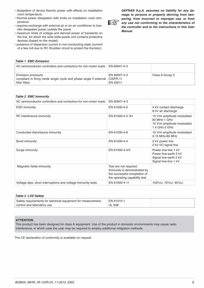
• dissipation of device thermic power with effects on installation room temperature.
• thermal power dissipation with limits on installation room tem-perature.
• requires exchange with external air or an air conditioner to tran-sfer dissipated power outside the panel.
• maximum limits of voltage and derived power of transients on the line, for which the solid state power unit contains protective devices (based on the model).
• presence of dispersion current in non-conducting state (current of a few mA due to RC Snubber circuit to protect the thyristor).
GEFRAN S.p.A. assumes no liability for any da-mage to persons or property deriving from tam-pering, from incorrect or improper use, or from any use not conforming to the characteristics of the controller and to the instructions in this User Manual.
AC semiconductor controllers and contactors for non-motor loads EN 60947-4-3
ESD immunity EN 61000-4-2 4 kV contact discharge8 kV air discharge
RF interference immunity EN 61000-4-3 /A1 10 V/m amplitude modulated 80 MHz-1 GHz10 V/m amplitude modulated 1.4 GHz-2 GHz
Conducted disturbance immunity EN 61000-4-6 10 V/m amplitude modulated 0.15 MHz-80 MHz
Burst immunity EN 61000-4-4 2 kV power line2 kV I/O signal line
Surge immunity EN 61000-4-4/5 Power line-line 1 kV Power line-earth 2 kVSignal line-earth 2 kVSignal line-line 1 kV
Magnetic fields immunity Test are not required. Immunity is demonstrated by the successful completion of the operating capability test
Voltage dips, short interruptions and voltage immunity tests EN 61000-4-11 100%U, 70%U, 40%U,
Table 2 EMC Immunity
Table 1 EMC EmissionAC semiconductor controllers and contactors for non-motor loads EN 60947-4-3
Emission enclosurecompliant in firing mode single cycle and phase angle if external filter fitted
EN 60947-4-3CISPR-11EN 55011
Class A Group 2
Safety requirements for electrical equipment for measurement, control and laboratory use
EN 61010-1UL 508
Table 3 LVD Safety
ATTENTIONThis product has been designed for class A equipment. Use of the product in domestic environments may cause radiointerference, in which case the user may be required to employ additional mitigation methods.
The CE declaration of conformity is available on request

6 80380A_MHW_IR-12/IR-24_11-2015_ENG
INSULATION DIAGRAM
220-
254V
ac50
/60H
z
CO
NTR
OL
LOG
IC
CPU
LO
GIC
I
N1,
IN2,
IN3,
IN4
OU
T1, .
..,O
UT4
LO
GIC
AC /
DC
+/-5
VAC
/ D
C5V
Low
vol
tage
+5Vd
c, 3
,3Vd
cC
ON
TRO
L LO
GIC
/ C
PU
Hig
h Vo
ltage
400
-480
Vac
Thre
e-ph
ase
+ N
eutra
l
Low
Vol
tage
5Vd
c Se
rial P
OR
T
SCR
OU
TPU
T
AC /
DC
5Vdc
O
UT
L1.
1 to
L1.
8
S
CR
9
Arm
s
AC /
DC
+24V
dc
Low
vol
tage
24V
dcFA
N
L1,
L2,L
3
VO
LTA
GE
M
EASU
RE
Exte
rnal
I/O
vol
tage
24
Vdc
FAN
1FA
N2
NTC
ove
r te
mpe
ratu
re
FUSE
L1.1 to L1.8
FUSE
L2.1 to L2.8
FUSE
L3.1 to L3.8
SSR
, FU
SE, L
OAD
di
agno
stic
Ser
ial P
OR
T M
OD
BU
S R
S485
or
FIE
LDB
US
O
UT
L2.
1 to
L2.
8
S
CR
9 A
rms
OU
T
L
3.1
to L
3.8
SC
R
9 Ar
ms

780380A_MHW_IR-12/IR-24_11-2015_ENG
2.4 Dimensions
Fastening can be done with five screw M6. See figures 1 and 2. All dimensions are expressed in mm.
Figure 1a - Dimensions of Models IR-24 and IR-12 with MODBUS RTU communication
Figure 1b - Dimensions of Models IR-24 and IR-12 with Fieldbus communication

8 80380A_MHW_IR-12/IR-24_11-2015_ENG
Figure 3
2.5 installation
Attention: respect the minimum distances shown in figure 3 to provide adequate air circulation.
2.4.1 TEMPLATE DIMENSIONSFigure 2
M6
980380A_MHW_IR-12/IR-24_11-2015_ENG
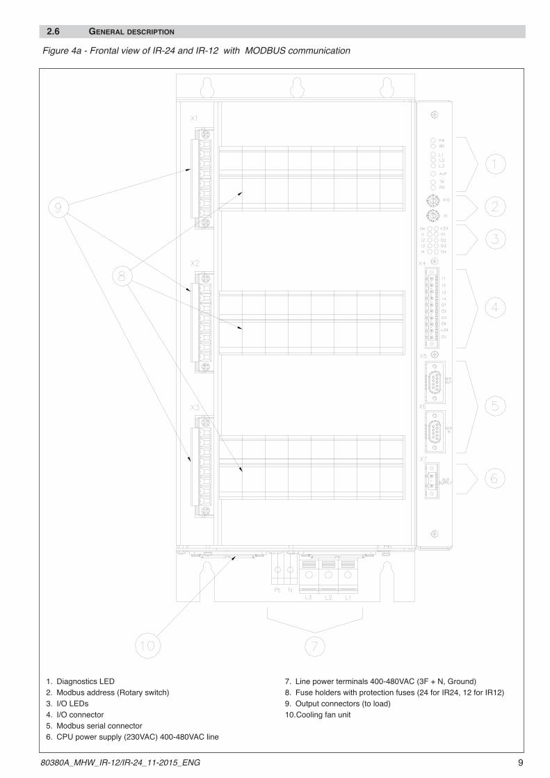
2.6 General DescriPtion
Figure 4a - Frontal view of IR-24 and IR-12 with MODBUS communication
1. Diagnostics LED 2. Modbus address (Rotary switch)3. I/O LEDs4. I/O connector 5. Modbus serial connector 6. CPU power supply (230VAC) 400-480VAC line
7. Line power terminals 400-480VAC (3F + N, Ground)8. Fuse holders with protection fuses (24 for IR24, 12 for IR12)9. Output connectors (to load)10. Cooling fan unit

10 80380A_MHW_IR-12/IR-24_11-2015_ENG
Figure 4b - Frontal View of IR-24 and IR-12 with Fieldbus PROFINET
1. Diagnostics Leds 2. Ethernet port ETH0, ETH13. I/O LEDs4. Ethernet port ETH0, ETH1 status Leds indication 5. I/O connector 6. CPU power supply (230VAC)
7. Line power terminals 400-480VAC (3F + N, Earth)8. Fuse holders with protection fuses (24 for IR24, 12 for IR12)9. Output connectors (to load)10. Cooling fan unit

1180380A_MHW_IR-12/IR-24_11-2015_ENG
2.7 cleaninG/checkinG or rePlacinG the fan
Figure 5
Fan suppy plug connector
Removable Fan Unit
Fan Unit fixing screws
NOTE: For IR-12 models, the fan Unit is provided with only one fan.

12 80380A_MHW_IR-12/IR-24_11-2015_ENG
PERIODIC CLEANING Every 6-12 months (depending on the dust level of the installation) blow a compressed air jet downward through the upper rectangular cooling grilles (on the side opposite the fan). This will clean the internal heat dissipater and the cooling fan.
IN CASE OF OVERHEAT ALARM ATTENTION: Before and during the inspection/maintenance cut power to the fan controller and verify that the system is isolated for operator safety.If periodic cleaning does not eliminate the problem, do as followsa Remove the cooling fan unit by unscrewing the 4 screws and sliding off the connector.b Disconnect the fan connector from the panelc Check the condition of the two fansd Clean or replace the fans Attention: check that the arrow (on the fan indicating the direction of air flow is pointing to the heat sinke Insert the connector into the panelf Insert the fan unit and fasten it with the 4 screwsg Power up the device and check fan rotation when at least one load is on.
2.8 rePlacinG the internal fuses
ATTENTION: Before and during the inspection/maintenance cut power to the fuses controller and verify that the system is isolated for operator safety.- Open the front cover (magnetic release)- This exposes the fuses - Pull the fuse holder outwards (remove the fuse)- Insert the new fuse.

1380380A_MHW_IR-12/IR-24_11-2015_ENG
3.1 Power connections
RECOMMENDED WIRE GAUGES
3 • ELECTRICAL CONNECTIONS
Table 4
MODEL TERMINAL /
CONNECTORCABLE SECTION TERMINAL TYPE TIGHTENING TORQUE /TOOL
IR24, IR12 L1, L2, L3 25-35 mm²4-2 AWG Tip / Stripped wire 4 ...4,2 Nm /
Flat-head screwdriver
IR24, IR12 PE 16-25 mm²6-4 AWG Tip / Stripped wire 2 ...2,2 Nm /
Flat-head screwdriver
IR24, IR12 N 1-16 mm²17-6 AWG Tip / Stripped wire 0,5 ...2,2 Nm /
Flat-head screwdriver
IR24, IR12 X1, X2, X3 2,5-4 mm²14-10 AWG Tip / Stripped wire 0,5 ...0,6 Nm /
Flat-head screwdriver
IR24, IR12 X7 1,5-2,5 mm²16-14 AWG Tip / Stripped wire 0,5 ...0,6 Nm /
Flat-head screwdriver
Defines address of module 00...99
(Only for models with MODBUS RS485 communication, please refer to figure N. 4a)
Table 6 Description of Rotary Switches
Switch Descriptionx10
x1
LED DESCRIPTION COLOR
PWW/D
CPU supply voltage ON green
Watch Dog tripped, CPU blocked yellow
L1L2L3
L1 phase voltage ON green
L2 phase voltage ON greenL3 phase voltage ON green
ALR One or more alarm conditions present red
TXRX
Status of serial line transmission greenStatus of serial line reception green
OK+24
Digital outputs functioning correctly green
24V voltage ON for digital I/Os greenI1 Status of digital input I1 greenI2 Status of digital input I2 greenI3 Status of digital input I3 greenI4 Status of digital input I4 greenO1 Status of digital output O1 greenO2 Status of digital output O2 greenO3 Status of digital output O3 greenO4 Status of digital output O4 green
3.2 functions of inDicator leDs Description of LEDsTable 6

14 80380A_MHW_IR-12/IR-24_11-2015_ENG
3.3 control connector
Connection schema X4 - Connector Digital I/O
PIN NAME DESCRIPTION1 I1 Digital input I12 I2 Digital input I23 I3 Digital input I34 I4 Digital input I45 O1 Digital output O16 O2 Digital output O27 O3 Digital output O38 O4 Digital output O49 +24V +24VDC power supply digital outputs
10 0V GROUND power supply digital inputs and outputs
CONNECTOR X4(CONTROL)
0,2 - 2,5mm2 24-14AWG
0,25 - 2,5mm2 23-14AWG
3.3.1 CONNECTOR X4 - DIGITAL I/O
Figure 6
Figure 7
Table 7
Table 8
1
2
3
4
5
6
7
8
9
10
LOA
D1
LOA
D2
LOA
D3
LOA
D4
24V dc
12
3
4
5
6
7
8
9
10
IN1IN2
IN3
IN4
+
-

1580380A_MHW_IR-12/IR-24_11-2015_ENG
3.3.2 CONNECTOR X5,X6 - modbus RS485
Figure 8
Cable type: Shielded
X4, X5 connector D-SUB 9 pin male
Nr. Pin Name
123456789
Descrption
1 2 3 4 5
6 7 8 9
For last module connected to serial line. Connect the termination resistor as shown in the figure (inside the connector).
Note
Data line
Data line
220
Pin 7 (+Tx / Rx)
Pin 8 (-Tx / Rx)
ohm
n.c.+ Tx/RxTerra
- Tx/RxGNDn.c.
+ Tx/Rx- Tx/Rx
n.c.
Not usedRS485 serial (A+)
Ground (cable shield)RS485 serial (B-)Serial GROUND
Not used(For termination)(For termination)
Not used
3.3.3 X7 CONNECTOR - 230VAC power supply
Figure 9
0,2 - 2,5mm2 24-14AWG
0,25 - 2,5mm2 23-14AWG
Table 9
1
2
1
2
AC S upply
AC S upply
230V ac

16 80380A_MHW_IR-12/IR-24_11-2015_ENG
3.4 connection examPle: Power section
Connection example: IR-24 connected to 24 loads
Figure 10a

1780380A_MHW_IR-12/IR-24_11-2015_ENG
Connection example: IR-12 connected to 12 loads
Figure 10b

18 80380A_MHW_IR-12/IR-24_11-2015_ENG
Example of operation in HSC mode with power at 33 and 66%.
Firing modes The IR24- IR12 power controllers have the following control modes:- modulation by variation of phase angle - modulation by variation of number of conduction cycles with “zero crossing”, Burst Firing or Half Single
Cycle firing
1 Burst Firing mode
BF -with variable cycle time This mode manages power on the load by means of a series of conduction (ON) and non-conduction (OFF) cycles. The ratio of the number of ON cycles to the number of OFF cycles is proportional to the power level to be supplied to the load. Repetition period CT is kept to the minimum for all power levels.
2 Optimized Burst Firing Mode
This mode manages power like BF, but optimizes conduction cycles among the various channels by shifting them in time in order to limit simultaneous conduction in all channels. A parameter defines the minimum number of conduction cycles settable from 1 to 10, in the following example, the parameter = 2.
Figure 11
Example of operation in BF mode with 50% power
3 Half Single Cycle Mode
HSC - Half single cycleThis mode corresponds to Burst Firing that manages ON and OFF half-cycles. It is useful for reducing theflickering of filaments with short/medium-wave IR lamp loads. With these loads, to limit operating current with
low power, it is useful to set a minimum power limit (for example, Lo.p = 10%).
Figure 12
Advanced single-cycle
P = 33% P = 66%

1980380A_MHW_IR-12/IR-24_11-2015_ENG
4 Phase angle (PA) This mode controls power on the load via modulation of trigger angle qExample: if power to be transferred to the load is 100%, q = 180° or if power to be transferred to the load is 50%, q = 90°
Figure 13
Resistive load Inductive load
ADDITIONAL FUNCTIONS
SoftstartThis type of start can be enabled to limit peak currents in IR lamps with initially cold filament.
Figure 14
Example of firing ramp with phase Soft-Start

20 80380A_MHW_IR-12/IR-24_11-2015_ENG
4 • INSTALLATION OF THE SERIAL PORTNOTE: - Chapter 4.0 and 4.1 are refered only to products with MODBUS communication. - For products with Fieldbus communication please refer to specific Fieldbus SW Manual
A network typically has a Master that “manages” communication by means of “commands,” and Slaves that carry out thesecommands.IR Control controller modules are considered Slaves to the network master, which is usually a supervision terminal or a PLC.It is positively identified by means of a node address (ID) set on rotary switches (tens + units).A maximum of 99 IR-12/IR-24 controller, modules can be installed in a serial network, with node address selectable from “01” to “99” IR-12/IR-24 controller modules have a ModBus serialThe MODBUS RTU port 1 has the following factory settings (default):
The following procedures are indispensable for the Modbus protocol.Set the rotary switch at “0+0” for AutoBaud function
Parameter Default RangeID 1 1...99BaudRate 57.6Kbit/s 1200...57600bit/sParity None Odd/Even/NoneStopBits 1 -
DataBits 8 -
ParameterPosition
rotary switches tens unit
AutoBaud 0 0 Allows setting of thecorrect BaudRate valueautomatically detecting the master transmission frequency
PLC / HMI IR Controlwith RS485
RS485 MODBUS DB9 Cable

2180380A_MHW_IR-12/IR-24_11-2015_ENG
4.1 “AUTOBAUD SERIAL 1” sequence
FunctionAdapt the serial communication speed and parity of the IR-12/IR-24 modules to the connected supervision terminal or PLC.
Procedure
1) Connect the serial cables for all modules on the network t and to the supervision terminal.
2) Set the rotary switch on the IR-12/IR-24 modules to be installed, or on all modules present in case of first installation, to position “0+0”.
3) The supervision terminal must transmit a series of generic “MODBUS” read messages to the network.
4) Wait at least 20 seconds.
The new speed parameter is saved permanently in each IR-12/IR-24; therefore, the “AUTOBAUD SERIAL” sequence does not have to be run at subsequent power-ups.
When the Autobaud procedure is done, set the Rotary Switches to the required address value.
INSTALLATION OF SERIAL NETWORK 1
ModBus
SETTING THE NODE ADDRESS
OPERATIVE FUNCTION
NO
The serial network communication speed is the same as for IR-12/IR-24 module.
?YES
“AUTOBAUD” SERIAL 1
SEQUENCE
Wait at least 20 seconds

22 80380A_MHW_IR-12/IR-24_11-2015_ENG
5 • TECHNICAL CHARACTERISTICSINPUTS
INDIG Digital Inputs Function N. 4 configurable digital inputsVoltage range 18-30V (max 15 mA) Safe voltage read status “0” < 15 VSafe voltage read status “1” > 18 V
Line voltage measurement Line voltage measurement function (F - N) Measure RMS voltage for each phase, phase/neutral
Working voltage range: 90...300VAC)Accuracy of RMS voltage measurement 1% f.s. at ambient temperature of 25°C
Thermal drift: < 100 ppm/°CLine frequency 50 / 60 Hz
OUTPUTSDIGITAL OUTPUTSFunction 4 configurable digital outputsType PNP Imax: 500mA protected against short circuit
24VDC external power supply
COMMUNICATION PORTS RS485 Modbus (Only for models with MODBUS communication)Function Local serial communication Protocol ModBus RTUBaudrate Settable 1200 …57600 bit/s (default 57.600Kbit/s)Node address Settable with 2 rotary-switchesType RS485 - DB9 dual connectorIsolation 500V
PROFINET FIELDBUS (Only for models with Profinet communication)Function Profinet-IO Slave Type N. 2 port RJ45 (ETH0, ETH1) Internal SwitchBaudrate 10/100Mbits base-tx, Autosensing, Autocrossover
Data transport Layer Ethernet II, IEEE 802.3Protocol PROFINET RTC - Real time Cyclic Protocol Class 1 & Class 2 (unsyncronized)
RTA - Real time Acyclic Protocol DCP - Discovery and Configuration Protocol
POWER (SOLID STATE POWER UNIT)CATEGORY OF USE(Tab. 2 EN60947-4-3)
AC 51 resistive loads or low inductionAC 55b infrared lamps
Firing modes PA - load control via modulation of firing phase angle BF - Burst Firing with variable cycle time.Optimized BF - like BF, but optimizes conduction cycles by shifting them in time in order to limit simultaneous firing of all channels (optimized distribution of currents)HSC - Half Single Cycle corresponds to Burst Firing that manages half-cycles of firing and stop cycles Useful for reducing flicker with short-wave IR loads
Three-phase line voltage compensation The line voltage compensation option can be selected to guarantee stable output power Max. nominal voltage 480Vac (Vf/n =270Vac) ± 10%Working voltage Max Range 50…530VacNon-repetitive voltage 1200VpNominal frequency 50/60Hz self-determinationNominal current AC51 -AC55b non-inductive or slightly inductive loads, IR lamps (@ Amb.T = 40°C) 9A for each output
Maximum output current 9A x 8 zones = 72A for each Threephase line (72A x 3)Dissipation For each zone = 1.2 V * ILOAD (Watts)Non-repetitive over-current (t=10msec) 500I²t for fusing (t=1…10msec) A²s 1250Critical Dv/dt with output deactivated 1000V/μsecRated impulse withstand voltage 4KVNominal current in short circuit 5KA

2380380A_MHW_IR-12/IR-24_11-2015_ENG
FUNCTIONSDiagnostics (for each zone) SSR short detection.
absence of line voltage, HB alarm (total load interrupt), blown fuse
OPTIONS Options - Timed Soft-Start firing ramp with phase angle control
- Soft-Start firing ramp specific for IR lamps Diagnostics - SCR in short circuit (presence of current with control OFF)
- Absence of current due to SCR open/load interrupted - Overtemperature alarm - HB interrupted load alarmVoltage read • No line voltage
NOTE1 : In PA_mode, the diagnostic Alarms Load-Open and Fuse_open are detected for SCR power firing higher than 40%.
NOTE2: In PA_mode, the diagnostic Alarm SSR-SHORT is detected when SCR power firing is P=0% or when its channel is disabled.
NOTE3: All diagnostics work with voltage line (F/N) between 200V and 305V.
GENERAL INFORMATIONPower supply CPU Board 230Vac ± 10%,
50-60 Hz 20VAPower supply for internal fan 24Vdc (internally provided)LEDs 18 Leds: for CPU status, Alarm diagnostic, I/O status, Threephase line detection.
(For details please refer to Table 6) Connection and load type Single-phase load (Phase/Neutral) 8 loads for each phase maximumProtection level IP20Working / Storage temperature 0…40°C Cooling N.2 fans 24Vdc - 3,6W (only one fan for IR-12 models)Relative humidity 10…95% Ur non-condensingAmbient operating conditions internal use, max. altitude 2000 metersInstallation Fastens to panel with screws Installation regulations Installation category II, pollution degree 2 -
Max. air temperature surrounding device 40°CWeight IR 24
14 Kg
IR 12 12 KgPacking dimensionsIR-12/IR-24 350 x 280 x 215mm

24 80380A_MHW_IR-12/IR-24_11-2015_ENG
This section contains information on order codes forthe Controller and its main accessories.
As mentioned in the Preliminary Instructions in thisUser Manual, a correct reading of the Controller order code
immediately identifies the unit’s hardware configuration.Therefore, you must always give the order code whencontacting Gefran Customer Care for the solution to anyproblems.
6 • TECHNICAL / COMMERCIAL INFORMATION
6.1 accessories
It is available the SW Configuration tool “GF-eXpress” cod. F043958, useful for quickIR-24 / IR-12 configuration using a PC with a USB / RS485 serial port.
It is also available the accessory cable USB/RS485 cod. F062615 useful for models with Modbus communication, to be connected to PC computer with USB port.
NUMBER OF ZONEs24 2412 12
IR -
6.2 fuses
ModelFUSES
Size I2 t
SignForm
ModelCode
Powerdissipation @ In
IR 24IR 12
32A600A² s
FUS-03210x38
FWC32A10F338483 1W
COMMUNICATIONM MODBUS RS485E4 PROFINET
MODEL DESCRIPTION CODEIR-12-M 12 Zones, Modbus RTU serial communication F062606IR-12-E4 12 Zones, Fieldbus Profinet serial communication F062611IR-24-M 24 Zones, Modbus RTU serial communication F062605IR-24-E4 24 Zones, Fieldbus Profinet serial communication F062612