
IPTV Testing over DSL - 123seminarsonly.com · The delivery of Internet protocol TV ... the video...
6
Telecom Test and Measurement www.EXFO.com The delivery of Internet protocol TV (IPTV) using DSL is an emerging and exciting technology that offers new business opportunities to service providers. ADSL2+ and VDSL2 data rates make it possible to easily integrate voice, video and data services over a single telephone line, commonly denominated triple-play services. With all these technological developments, it is now practical and economical to simultaneously provide multiple standard and high-definition television channels (SDTV and HDTV) to the residential user. The term IPTV usually includes a broad range of programs or TV channels provided by one or multiple service providers. Additionally, it might include some specialized programming like concerts, special events and movies, provided only when requested by the user; i.e., video on demand (VoD). Like every other evolving technology, there are multiple approaches for the delivery of IPTV across the core network and its transmission to the customer premises over an ADSL2+ connection. In general, video service providers first perform the coding and compression of the video signal typically using MPEG-2, MPEG-4 or WM9/VC-1 (it is at this stage that a trade-off between quality and required bandwidth occurs). Then, the video content is ready to be distributed by streaming IP packets using the user-datagram protocol (UDP), which is the preferred method of IP packet delivery when offering video due to its low latency. Once at its final destination, the subscriber’s house, the video stream is decoded by a set-top box (STB) and played on the TV. This document discusses the basic properties that define video over ADSL2+ streaming, the measurement principles behind IPTV quality of service (QoS), as well as how EXFO’s CoLT-450P can play a role in helping to deliver high-quality video services. Quality of IPTV On any ADSL-based deployment, the quality of the consumer’s video is not just a function of the network bandwidth (ADSL2+/ADSL) or the data stream, as there are a number of parameters that contribute to the customers’ perception of good vs. bad quality. As the video stream arrives to the set- top box and ultimately the television, it has gone through various protocol layers (e.g., physical ADSL layer, ATM layer, IP layer, transport layer, etc.). It is the interaction between these layers and the effect of external influences that affect the quality of the video perceived by the consumer; this is often referred to as quality of experience (QoE). Some of the parameters that influence the customer’s QoE include image pixelization and tiling, picture blurring and edge distortion, as well as audio dropouts and channel-change latency (also known as zap time). 148 APPLICATION NOTE IPTV TESTING OVER DSL Francisco Palacios, Product Manager, Copper Access Business Unit Figure 1: Typical IPTV-over-DSL network
Transcript of IPTV Testing over DSL - 123seminarsonly.com · The delivery of Internet protocol TV ... the video...

Telecom Test and Measurement
www.EXFO.com
The delivery of Internet protocol TV (IPTV) using DSL is an emerging and exciting technology that offers new business opportunities to service
providers. ADSL2+ and VDSL2 data rates make it possible to easily integrate voice, video and data services over a single telephone line, commonly
denominated triple-play services. With all these technological developments, it is now practical and economical to simultaneously provide multiple
standard and high-definition television channels (SDTV and HDTV) to the residential user.
The term IPTV usually includes a broad range of programs or TV channels provided by one or multiple service providers. Additionally, it might include
some specialized programming like concerts, special events and movies, provided only when requested by the user; i.e., video on demand (VoD).
Like every other evolving technology, there are multiple approaches for the delivery of IPTV across the core network and its transmission to the
customer premises over an ADSL2+ connection. In general, video service providers first perform the coding and compression of the video signal
typically using MPEG-2, MPEG-4 or WM9/VC-1 (it is at this stage that a trade-off between quality and required bandwidth occurs). Then, the video
content is ready to be distributed by streaming IP packets using the user-datagram protocol (UDP), which is the preferred method of IP packet delivery
when offering video due to its low latency. Once at its final destination, the subscriber’s house, the video stream is decoded by a set-top box (STB) and
played on the TV.
This document discusses the basic properties that define video over ADSL2+ streaming, the measurement principles behind IPTV quality of service
(QoS), as well as how EXFO’s CoLT-450P can play a role in helping to deliver high-quality video services.
Quality of IPTVOn any ADSL-based deployment, the quality of the
consumer’s video is not just a function of the
network bandwidth (ADSL2+/ADSL) or the data
stream, as there are a number of parameters that
contribute to the customers’ perception of good vs.
bad quality. As the video stream arrives to the set-
top box and ultimately the television, it has gone
through various protocol layers (e.g., physical
ADSL layer, ATM layer, IP layer, transport layer,
etc.). It is the interaction between these layers and
the effect of external influences that affect the
quality of the video perceived by the consumer; this
is often referred to as quality of experience (QoE).
Some of the parameters that influence the
customer’s QoE include image pixelization and
tiling, picture blurring and edge distortion, as well
as audio dropouts and channel-change latency
(also known as zap time).
148APPLICATION NOTE
IPTV TESTING OVER DSL
Francisco Palacios, Product Manager, Copper Access Business Unit
Figure 1: Typical IPTV-over-DSL network

Telecom Test and Measurement
www.EXFO.com
A typical IPTV configuration from the digital subscriber line access
multiplexer (DSLAM) to the customer premises is shown in Figure 2.
As shown, the video stream is delivered using ADSL2+ from the IP-
based DSLAM to the user’s ADSL2+ broadband router. The router,
while supporting voice and Internet service, passes the video stream to
the STB for decoding. The STB converts the video stream into required
signals for displaying on the consumer’s TV.
Factors Affecting Service
Encoding and CompressionThe quality of the video being distributed across the network can be
affected right at the source; i.e., at the video head end. The encoding
and compression process usually creates a trade-off between the quality
of the video and the desired compression level. In addition, depending
on the encoding and compression technique used, the amount of video
information per IP packet will vary. Therefore, an IP packet loss can
represent a single unnoticeable missing point of the video sequence or a
large period of degraded, pixelated or unavailable image.
JitterA typical IP packet carrying MPEG-2 video-streaming data consists of seven MPEG transport stream packets, each containing 184 bytes of payload
and 4 bytes of header. This results in 1316 bytes, plus the packet overhead – 8 bytes for the UDP header, 20 bytes for the IP header, 14 bytes for the
Ethernet header and 10 bytes for ATM overhead – for a total frame size of 1368 bytes.
Jitter is defined as a short-term variation in the packet arrival time, typically caused by
network or server congestion. If the Ethernet frames arrive at the STB at a rate that is
slower or faster, as determined by the network conditions, buffering is required to help
smooth out the variations. Based on the size of the buffer, there are delivery conditions
that can make the buffer overflow or underflow, which results in a degradation of the
perceived video. Similarly, knowing the characteristics of a specific STB, the service
provider might be able to characterize the maximum jitter supported by the IPTV network
before noticing a considerable video degradation. This value will be a decisive factor
when analyzing the video QoS at the customer premises.
Limited BandwidthThe total amount of video-stream data that can be sent is limited ultimately by the customer’s actual ADSL/ADSL2+ rate. Core IP infrastructure is
usually based on optical networks with a low level of congestion; therefore, bandwidth limitations are commonly located only within the access network
or the customer’s home network. When traffic levels hit the maximum bandwidth available, packets are discarded, leading to video quality degradation.
ADSL2+ rates may be temporarily affected by external factors, which in turn can generate pixelization of the image.
Another situation might occur when, in addition to the IPTV service, a high amount of data is downloaded simultaneously to a PC and the traffic
priorities have not been assigned correctly by the service provider; in these cases, video streaming packets are lost. A less common but important case
is when video is streamed in variable-rate mode, in which considerable changes in the video sequences lead to an increase in the bandwidth
requirement. This can generate packet loss and hence quality degradation.
Bandwidth limitation is one of the main factors to be evaluated during the network design stage.
Application Note 148
Figure 2: Typical IPTV configuration
Figure 4: Pixelated image
Figure 3: Frame for MPEG-2 Video

Telecom Test and Measurement
www.EXFO.com
Packet Loss Loss of IP packets may occur for multiple reasons — bandwidth limitations, network
congestion, failed links, and transmission errors. Packet loss usually presents a bursty
behavior, commonly related to periods of network congestion. Depending on the type of
transport protocol used for the video streaming, a packet loss will have different impact
on the quality of the perceived video. When UDP is used, the lost packets will directly
affect the image, as the information cannot be recovered and the image will simply be
corrupt or unavailable. When using TCP, a packet loss will generate a retransmission,
which can produce a buffer underflow and, consequently, a possible frozen image.
Ensuring High-Quality IPTV ServicesBelow is a five-step approach for IPTV service installation and troubleshooting.
This method provides the technician with an easy-to-remember procedure that can be performed from the network interface device (NID) or from the
customer TV room.
Step 1: Check the rates of the ADSL/ADSL2+ link Data rates for the downstream and upstream must be high enough to support IPTV. Even with MPEG-2 or MPEG-4 video compression, a speed of at
least 3 Mb/s per channel is required in the downstream direction — and much more if HDTV is contemplated.
Step 2: Ensure that DSL rates are stableSignal-to-noise ratio margin (SNRm) must be better than 6 dB and preferably more than 10 dB. Some DSL modems and DSLAMs are pre-configured
to operate at the highest possible rate with longest reach by trimming the SNRm. Although this trimming would produce a higher rate, it would
introduce errors. This situation was somewhat tolerable for data being delivered in TCP/IP when dealing only with Internet traffic, but it is highly
detrimental to IPTV quality. Typically, errors manifest themselves in a pixelization of the video or a complete loss of video feed.
Step 3: Be sure that ATM errors are consistently lowPresence of impulse noise can generate multiple errors at the DSL layer, especially if the SNRm is low, as previously indicated. Some other loop issues
can also affect the ATM payload directly. These errors are most likely related to the local loop, and therefore a thorough narrowband and wideband
evaluation of the cooper loop is recommended.
Step 4: Test IP and MPEG video layersOnce the ADSL or ADSL2+ link has been tested for rates, SNRm and ATM-layer errors, the next step is to test the IP and MPEG video layers.
If a video channel is being streamed over the DSL line, the IP and video transport stream can also be evaluated for rates and errors.
Any existing correlation between errors and sudden variations of the stream data rate may be an indication that the video is exceeding the available
bandwidth; therefore, some adjustments will be needed at the video streaming source.
On the other hand, the user must ensure that Internet Group Management Protocol (IGMP) requests, used to join and leave IPTV channels, are being
properly handled by the network. Channels must change correctly and under a certain amount of time, as determined by the target zapping time.
Step 5: Confirm the video quality for at least 15 minutesEvaluate the quality of video over a certain period of time. At least 15 minutes is recommended. If an error on the ATM layer results in an IP-layer error, it
will also affect the video quality. An IP-layer error that does not coexist with an ATM-layer error generally originates further back in the IP network and
will be usually experienced by multiple subscribers. Therefore, no remedial action is possible on the local loop.
QoS indicators like jitter, packet-loss percentage and zapping time must be monitored during this entire time, as they will provide an objective
confirmation that the video being received complies with the minimum standard of quality as set by the IPTV service provider.
Due to the different network topologies and network environments, thresholds for these parameters are often defined by each service provider.
Application Note 148
Figure 5: Edge distortion
Telecom Test and Measurement
www.EXFO.com
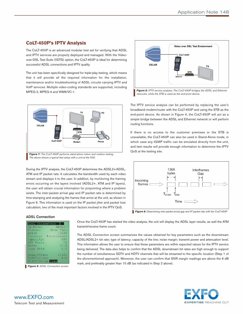
CoLT-450P’s IPTV AnalysisThe CoLT-450P is an advanced modular test set for verifying that ADSL
and IPTV services are properly deployed and managed. With the Video-
over-DSL Test Suite (VDTS) option, the CoLT-450P is ideal for determining
successful ADSL connections and IPTV quality.
The unit has been specifically designed for triple-play testing, which means
that it will provide all the required information for the installation,
maintenance and/or troubleshooting of ADSL circuits carrying IPTV and
VoIP services. Multiple video-coding standards are supported, including
MPEG-2, MPEG-4 and WM9/VC-1.
The IPTV service analysis can be performed by replacing the user’s
broadband modem/router with the CoLT-450P and using the STB as the
end-point device. As shown in Figure 4, the CoLT-450P will act as a
simple bridge between the ADSL and Ethernet network or will perform
routing functions.
If there is no access to the customer premises or the STB is
unavailable, the CoLT-450P can also be used in Stand-Alone mode, in
which case any IGMP traffic can be emulated directly from the unit,
and test results will provide enough information to determine the IPTV
QoS at the testing site.
During the IPTV analysis, the CoLT-450P determines the ADSL2+/ADSL,
ATM and IP packet rate. It calculates the bandwidth used by each video
stream and displays it to the user. In addition, by monitoring the framing
errors occurring on the layers involved (ADSL2+, ATM and IP layers),
the user will obtain crucial information for pinpointing where a problem
exists. The inter-packet arrival gap and IP packet rate is determined by
time-stamping and analyzing the frames that arrive at the unit, as shown in
Figure 6. This information is used on the IP packet jitter and packet loss
calculation, two of the most important factors involved in the IPTV QoS.
ADSL ConnectionOnce the CoLT-450P has started the video analysis, the unit will display the ADSL layer results, as well the ATM
transmit/receive frame count.
The ADSL Connection screen summarizes the values obtained for key parameters such as the downstream
ADSL/ADSL2+ bit rate; type of latency; capacity of the line; noise margin; transmit power and attenuation level.
This information allows the user to ensure that these parameters are within expected values for the IPTV service
being delivered. The data also helps to confirm that the ADSL downstream bit rates are high enough to support
the number of simultaneous SDTV and HDTV channels that will be streamed to the specific location (Step 1 of
the aforementioned approach). Moreover, the user can confirm that SNR margin readings are above the 6 dB
mark, and preferably greater than 10 dB (as indicated in Step 2 above).
Application Note 148
Figure 7: The CoLT-450P performs stand-alone indoor and outdoor testing.The above shows a typical test setup with a unit at the NID.
Figure 8: Determining inter-packet arrival gap and IP packet rate with the CoLT-450P
Figure 6: IPTV service analysis: The CoLT-450P bridges the ADSL and Ethernetnetworks, while the STB is used as the end-point device.
Figure 9: ADSL Connection screen

Telecom Test and Measurement
www.EXFO.com
Network StatusThe STB Information screen allows the user to confirm the line configuration of the CoLT-450P. It includes the
VPI/VCI information as well the type of encapsulation used on the ADSL side. The unit also provides specific
information for the different STBs operating on the LAN side of the CoLT-450P.
Data like MAC and IP addresses for the STB is also displayed, which may be useful in case any troubleshooting
between the STB and the broadband router (or CoLT-450P) is required. For example, the user can quickly determine
if a specific STB is being detected by the CoLT-450P; it is also possible to pinpoint problems with the Ethernet
cabling and/or the STB itself.
Stream AnalysisThe Video Stream Analysis screen provides a comprehensive breakdown of the rates available at the different layers related to the IPTV service, as well
as a summarized description of the multiple streams detected.
At the top of the screen, the CoLT-450P displays the data rates for the ADSL, ATM and IP layers. The ATM rate is
determined by the virtual channel (VC) configuration, where the service is located. The IP packet rate, on the other
hand, is based on the MPEG-2, MPEG-4 or WM9/VC-1 streams detected on the line. This information allows the
user to determine the amount of bandwidth used by the video service in comparison to the total available bandwidth.
As the number of simultaneous IPTV channels being streamed to the STBs increase, data rates, and consequently
utilization levels, increase as well.
An IPTV channel being multicasted to any STB located on the LAN side of the unit will be detected. The multicast IP
address, stream rate and bandwidth utilization is displayed for each of the detected channels (represented as a
portion of the total ATM rate).
The multicast IP address helps to determine the specific channel being received, while stream rates indicate how much bandwidth is consumed by
each of the channels. A stable constant bit rate (CBR) stream will ideally keep the same value all the time; a changing rate when using CBR will
indicate a problem at the video head end.
IGMP Packet StatisticsThe IGMP Statistics screen allows the user to confirm that IGMP traffic is being transferred between the central
network and the STB. The network frequently queries the STB and consequently receives a report package from the
remote device. These counters are displayed by the CoLT-450P.
Join and leave IGMP requests are also presented to the user. These are useful values to confirm that the STB is
properly sending these requests to the network; in exchange, the network should respond with a channel change as
requested. The time required for the channel change is reported as “zap time”.
If there is no increment on the join/leave request counter, it can be an indication that a problem may exist with the
STB; the issue can simply be related to the remote control, to internal processing or to the Ethernet connection to
the broadband router.
Multicast IP addresses for any joined or left channels are logged and showed on the screen.
IPTV Service ErrorsThe CoLT-450P’s video stream monitor detects and provides error information for the ADSL, ATM and IP layer, as well as counting of frames that
required forward error correction (FEC). Please note that FEC will not be available on systems with fast latency.
The tester generates a graph representing a five-minute monitor window where events like FEC, DSL frame errors, ATM and IP packet loss are
registered. These three-second sample marks provide a time reference for the errors.
FEC values represent erroneous data that could be corrected. A high number of FEC marks may indicate that a potential problem exists on the local
loop or ADSL layer. Errors on ADSL frames are a clear indication of problems on the local loop or DSLAM, and a deeper copper analysis is
Application Note 148
Figure 12: IGMP Statistics screen
Figure 11: Stream Analysis screen
Figure 10: Network Status screen

recommended using EXFO’s CableSHARK. On the other hand, errors on an ATM level can be attributed to
DSLAM problems, and if an ATM backbone is still in place, issues may also be related to the ATM switch.
IP packet loss, caused by errored and out-of-sequence packets, are usually the ones related to the IP core and
video head end; bandwidth limitations, network congestion, failed links and transmission problems can be some of
the reasons. Due to the centralized nature of the problem, issues on the IP layer are usually experienced
simultaneously by multiple subscribers.
Unrecoverable errors in the ADSL or ATM layers will most probably be reflected in higher layers like IP.
Typically, an IP packet loss will result in noticeable pixelization by the user.
At the bottom of the screen, the user can monitor the video-streaming rate. Each line represents the video rate a
certain time, so any fluctuation on this curve represents bit rate variations on the video signal. An auto-adjustable horizontal dashed line above the
curve is used as a reference for the maximum rate. Bit rates are presented in Mb/s.
JitterThe Maximum Stream Jitter graph provided by the CoLT-450P represents a five-minute monitor window where
the maximum jitter for the video stream is registered.
Each network will require specific levels of maximum jitter before perceiving degradation of the video.
The STB’s buffer size will help to determine tolerable levels of jitter in the network. It is recommended that each
service provider define their own jitter thresholds based on the local network characteristics.
QoS SummaryEXFO’s CoLT-450P provides the user with a QoS Summary screen that displays a simple Pass/Fail mark for the
factors affecting IPTV quality of service. Of course, thresholds must be set according to local network
characteristics so as to ensure optimum results, but accurate IP packet loss, jitter and zap time readings are all
displayed in a tidy and efficient results window, providing a clear overview of the QoS at a glance.
The CoLT-450P is the right tool for service confirmation testing, maintenance and troubleshooting, making IPTV
quality assessment a simple task.
Appnote148.1AN © 2006 EXFO Electro-Optical Engineering Inc. All rights reserved. Printed in Canada 06/06
EXFO Corporate Headquarters > 400 Godin Avenue, Quebec City (Quebec) G1M 2K2 CANADA Tel.: 1 418 683-0211 Fax: 1 418 683-2170 [email protected]
Toll-free: 1 800 663-3936 (USA and Canada) www.EXFO.com
EXFO Montreal 2650 Marie-Curie St-Laurent (Quebec) H4S 2C3 CANADA Tel.: 1 514 856-2222 Fax: 1 514 856-2232EXFO Toronto 160 Drumlin Circle Concord (Ontario) L4K 3E5 CANADA Tel.: 1 905 738-3741 Fax: 1 905 738-3712 EXFO America 3701 Plano Parkway, Suite 160 Plano, TX 75075 USA Tel.: 1 800 663-3936 Fax: 1 972 836-0164 EXFO Europe Omega Enterprise Park, Electron Way Chandlers Ford, Hampshire S053 4SE ENGLAND Tel.: +44 2380 246810 Fax: +44 2380 246801EXFO Asia 151 Chin Swee Road, #03-29 Manhattan House SINGAPORE 169876 Tel.: +65 6333 8241 Fax: +65 6333 8242EXFO China No.88 Fuhua, First Road Shenzhen 518048, CHINA Tel.: +86 (755) 8203 2300 Fax: +86 (755) 8203 2306
Central Tower, Room 801, Futian DistrictBeijing New Century Hotel Office Tower, Room 1754-1755 Beijing 100044 P. R. CHINA Tel.: +86 (10) 6849 2738 Fax: +86 (10) 6849 2662No. 6 Southern Capital Gym Road
Application Note 148Application Note 148
Figure 14: Jitter Monitor screen
Figure 15: Test Summary screen
Figure 13: Error/Rate Monitor screen