IPS-M-EL-176(1) - det-mop.irdet-mop.ir/IPS/el/m-el-176.pdf · DOCUMANTATION ... IEC 60993...
18
IPS-M-EL-176(1)
Transcript of IPS-M-EL-176(1) - det-mop.irdet-mop.ir/IPS/el/m-el-176.pdf · DOCUMANTATION ... IEC 60993...

IPS-M-EL-176(1)

JULY 2003
IPS-M-EL-176(1)
1
FOREWORD
This Standard is intended to be used within and for Iranian Ministry of Petroleum (N.I.O.C, N.I.G.C, N.P.C., N.I.O.R.D.C. and other affiliate organizations and companies) and has been prepared on the basis of the recognized standards, scientific publications, technical documents, accumulated knowledge and experiences in petroleum industries at national and international levels.
Iranian Petroleum Standards are prepared by Iranian Petroleum Standards Organization reviewed and amended by the relevant technical standard committees to incorporate acceptable comments made by oil, gas and petrochemical experts.
Standards are finally approved by the “Standards High Council” of Iranian Ministry of Petroleum.
Iranian Petroleum Standards (IPS) are subject to amendment withdrawal, if required, thus the latest edition of IPS shall be applicable.
Any comment or recommendation submitted to the “Iranian Petroleum Standards Organization” will be evaluated in the relevant technical committee and will be considered in the next revision, upon approval.
GENERAL DEFINITIONS:
Throughout this Standard the following definitions shall apply.
“COMPANY” : Refers to one of the related and/or affiliated companies of the Iranian Ministry of Petroleum such as National Iranian Oil Company, National Iranian Gas Company, National Petrochemical Company etc.
“PURCHASER” : Means the “Company “ Where this standard is part of direct purchaser order by the “Company”, and the “Contractor” where this Standard is a part of contract documents.
“VENDOR” and “SUPPLIER” : Refers to firm or person who will supply and/or fabricate the equipment or material.
“WILL” : Is normally used in connection with the action by the “Company” rather than by a contractor, supplier or vendor.
“MAY” : Is used where a provision is completely discretionary.
“SHOULD” : Is used where a provision is advisory only.
“SHALL” : Is used where a provision is mandatory.
IRANIAN PETROLEUM STANDARDS.
No. 19, Street 14, North Kheradmand Karimkhan Avenue, Tehran, Iran. Tel. : 66153055 : 88810460 Fax. : 88810462

JULY 2003
IPS-M-EL-176(1)
2
JULY 2003
MATERIAL AND EQUIPMENT STANDARD
FOR
UNINTERRUPTIBLE POWER SYSTEM
(UPS)
FIRST EDITION
JULY 2003
This Standard is the property of Iranian Ministry of Petroleum. All rights are reserved to the owner. Neither whole nor any part of this document may be disclosed to any third party, reproduced, stored in any retrieval system or transmitted in any form or by any means without the prior written consent of the Iranian Ministry of Petroleum

JULY 2003
IPS-M-EL-176(1)
3
CONTENTS : PAGE No.
1. SCOPE ............................................................................................................................................ 4
2. REFERENCES ................................................................................................................................ 4
3. SERVICE CONDITIONS ................................................................................................................. 5
4.OPERATING PRINCIPLE ................................................................................................................ 5
5. UPS SYSTEM CONFIGURATION.................................................................................................. 5
6.ELECTRICAL CHARACTERISTICS ............................................................................................... 6
7. GENERAL REQUIREMENTS ......................................................................................................... 6
8. RECTIFIER/CHARGER CONSTRUCTION .................................................................................... 9
9. BATTERY........................................................................................................................................ 9
10. INVERTER CONSTRUCTION .................................................................................................... 10
11. BYPASS CIRCUIT ...................................................................................................................... 11
12. TESTS AND INSPECTION ......................................................................................................... 12
13. SPARE PARTS ........................................................................................................................... 12
14. DOCUMANTATION .................................................................................................................... 12
15. PACKING FOR SHIPMENT........................................................................................................ 13
16. GUARANTEE.............................................................................................................................. 13
APPENDICES:
APPENDIX A UPS DATA SHEET .................................................................................................... 14
APPENDIX B ARRANGEMENT OF UPS SYSTEM......................................................................... 15
APPENDIX C APPLICABLE DEFINTIONS FOR THIS SPECIFICATION....................................... 16
JULY 2003
IPS-M-EL-176(1)
4
1. SCOPE
1.1 This Standard specification covers the minimum requirements for design, manufacture, quality control and testing of Uninterruptible Power Supply system (UPS) which will be installed in oil, gas and petrochemical industries in Iran under the service conditions stated herein.
1.2 Only the general requirements are given in this specification, the specific requirements, if any, will be given in request for quotation and / or purchase order.
Note: This is a revised version of the standard specification for uninterruptible power supply which is issued as revision (1). Revision (0) of the said standard specification is withdrawn.
2. REFERENCES
2.1 The Uninterruptible Power Supply system shall be designed, constructed, wired and tested in accordance with applicable sections of the latest edition of international electrotechnical commission “IEC” standards, in particular the following:
IEC 60051 Measuring Instruments and their Accessories
IEC 60073 Colors of Indicator Lights and Pushbuttons
IEC 60076 Power Transformer
IEC 60119 Recommendations for Polycrystalline Semiconductor Rectifier Stacks and Equipment
IEC 60146 Semiconductor Converters
IEC 60289 Reactors
IEC 60445 Identification of equipment terminals and of terminations of certain designated conductors
IEC 60529 Classification of Degrees of Protection Provided by Enclosures
IEC 60622 Sealed Nickel Cadmium Prismatic Rechargeable Single Cells
IEC 60623 Vented Nickel Cadmium Prismatic Rechargeable Single Cells
IEC 60896 Stationary Lead Acid Batteries
IEC 60947-3 Low voltage switches, Disconnectors, switch disconnectors and Fuse Combination Units
IEC 60993 Electrolyte for Vented Nickel Cadmium Cell
IEC 62040-3 Uninterruptible power systems-methods of specifying the performance and test requirements
2.2 Where standards other than IEC are specified, it is understood that the equivalent IEC standard is acceptable.
2.3 Any deviation from this specification and the above mentioned references shall be clearly mentioned in the vendor’s proposal.
2.4 In the event of conflict between the text of this document and the references cited herein, the text of this document takes precedence.

JULY 2003
IPS-M-EL-176(1)
5
3. SERVICE CONDITIONS
3.1 Unless otherwise specified in the data sheet, the equipment under this specification will be installed inside ventilated room/s with following ambient conditions:
- Maximum ambient air temperature 40ºC
- Minimum ambient air temperature 5ºC
- Relative humidity 90%
- Site elevation will be given in data sheet (Appendix A)
4.OPERATING PRINCIPLE
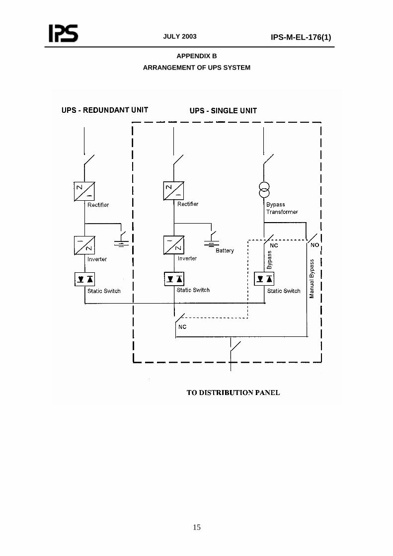
4.1 Each UPS unit shall consist of a rectifier/charger, an inverter, batteries, an static transfers switch, a maintenance bypass switch, and when required, a bypass transformer.
4.2 During normal operation, a source of alternating current will supply energy to the UPS unit. A rectifier converts incoming AC power to DC which supplies the inverter and charges the batteries. The inverter changes the DC to AC power which supplies electrical energy to the critical loads through the static transfer switch.
4.3 The output of the rectifier shall continuously supply the power requirements of the load, through the inverter, while simultaneously maintaining the battery in the float charge mode.
4.4 In the event of an interruption or depression in the AC mains voltage, the battery shall supply the power requirements of the load via the inverter.
4.5 Upon restoration of the A.C. mains voltage, the rectifier shall supply the power requirements of the load via the inverter, while simultaneously recharging the battery.
4.6 The UPS unit shall be equipped with a static transfer switch and, when required, a bypass transformer. The output voltage and frequency of the inverter shall be kept synchronized with the bypass supply.
4.7 In case where the inverter voltage and frequency deviates from the specified tolerances, the static switch initiates uninterrupted transfer of the load to the bypass supply.
4.8 Upon restoration of the inverter output voltage and frequency, the load shall be automatically transferred back to the inverter which resumes synchronous operation with the bypass supply.
4.9 A make before break switch shall also be provided, for manual transfer of the load to the bypass power supply, in order to isolate the rectifier, inverter and static transfer switch for maintenance purposes.
5. UPS SYSTEM CONFIGURATION
5.1 The UPS system will be used for supplying power to computers and digital electronic equipment, process control instrumentation, fire and gas detection systems, shutdown and interlock systems, analyzers, intra-plant communication systems, PABX and other critical electrical AC loads.
5.2 The UPS system adopted for different types of AC loads can consist of one or two units. The numbers of required units will be indicated in data sheet, Appendix A.
5.3 Generally one single UPS unit of manufacturer standard size shall be used. For special critical loads, duplicate units shall be applied.

JULY 2003
IPS-M-EL-176(1)
6
5.4 When duplicate unit configuration is selected, the units shall operate in parallel, to share the load, and shall energize a single distribution panel. Both units are to be fed from synchronized AC supply.
5.5 Each unit of duplicate unit configuration system shall be rated for 100% of the rated capacity, so that, when one unit fails or switched off, the other unit shall accepts the total load.
5.6 For duplicate units one single bypass supply shall be provided, which shall be synchronized with both inverters output. The bypass supply shall also be rated for 100% of the rated capacity. The arrangement of such configuration is shown in Appendix B.
5.7 Duplicate units shall include appropriate control circuitry to facilitate equal sharing of the load between the two units. The load sharing control circuit shall not be subject to common mode failure, and shall in no case, cause tripping of both inverters.
5.8 Where this specification is used as a part of an EPC contract, the EPC contractor shall determine the rated capacity of the UPS system to meet the project requirement according to paragraph 6.4 of this specification, and the company representative will decide on the system configuration.
6. ELECTRICAL CHARACTERISTICS
6.1 The AC power supply to the UPS unit/s will be symmetrical three phase 400 volt 50 Hertz with solidly earthed neutral.
For small size UPS unit/s single phase 230 volt supply voltage, one phase and earthed neutral may be selected. This will be indicated in the data sheet, Appendix A. Use of single phase supply voltage for UPS units above one KVA is not recommended.
6.2 The input voltage variation will be ± 10% and the frequency variation will be ± 5%. In addition to the above variations, the input voltage may be subject to short time voltage dips up to 20% during motor starting, and also transient high frequency voltages during system switching operations.
6.3 The output voltage and numbers of phases will be specified in data sheet. The output voltage variation shall be limited to ±1%. The output frequency shall be 50 Hertz and shall be maintained within ±1%.
6.4 The rated capacity of the UPS unit/s will be indicated in data sheet. The rated capacity shall include 20 per cent spare capacity over the estimated load, in order to accommodate future loads. The rated capacity shall be based on IEC 60146.
6.5 The UPS unit/s shall be capable to feed the loads with power factor between 0.7 lagging and unity.
6.6 Unless otherwise specified in data sheet, the output power of UPS unit/s with rating up to and including 30 KVA shall be single phase and neutral. The output power of units rated above 30 KVA can be 3 phase and neutral, if specified in data sheet. In general, single phase output is preferred.
6.7 The neutral of the UPS output voltage/s shall be solidly earthed.
7. GENERAL REQUIREMENTS
7.1 The UPS unit/s shall be modular in design allowing for easy maintenance, and shall be electronically regulated type.
7.2 The UPS components viz. rectifier, inverter, static transfer switch and manual bypass switch shall be designed for continuous and reliable operation such that the mean time between failures (MTBF) for individual components shall be more than 8760 hours or one year of operation.

JULY 2003
IPS-M-EL-176(1)
7
7.3 To ensure minimum down time, the mean time to repair (MTTR) of the UPS components shall not exceed one hour.
7.4 The UPS components shall be installed in suitable free standing floor mounted or wall mounted steel enclosure/s fabricated from sheet steel with a minimum thickness of 1.5 mm. Unless otherwise specified in the data sheet the enclosure shall provide a degree of protection of at least IP31, according to IEC 60529.
7.5 The enclosure/s shall be cleaned, primed, and painted in accordance with the manufacturer’s standard practice. The complete interior surface of the enclosure/s shall have a final coat of moisture and fungus resistant varnish.
7.6 The enclosure/s shall be arranged for front operation. Rear access will not be required.
7.7 Gland plates shall be provided within the enclosure/s for purchaser’s cables. Unless otherwise specified, the purchaser’s cables enter the enclosure from the bottom.
7.8 Lifting lugs shall be provided on each enclosure, for ease of handling.
7.9 Suitable terminal blocks shall be provided for connection of purchaser’s power cables and grounding cables. All terminals shall be clearly marked. The identification of terminals shall be in accordance with IEC 60445.
7.10 An earth rail with sufficient numbers of earthing bolts or screws shall be provided to facilitate termination of earthing cables and cables, armours. The earth rail shall be connected to the enclosures structure. The neutral of the inverter output shall be connected to the earth rail.
7.11 Transformers and reactors used in the construction of the UPS shall be dry type air cooled and shall comply with IEC 60076 and IEC 60289 plus extra requirements of IEC 60146.
7.12 Internal cooling of the enclosure/s can be natural or by forced air ventilation. Where forced air ventilation is adopted, two fans shall be used so that the unit delivers the rated output power with only one ventilation fan in service. In case of failure of the operating fan, the second fan shall be automatically energized. The ventilation fans shall be powered from the UPS output.
7.13 Permanent nameplates shall be provided to identify each instrument, switch, meter, relay, etc. on the enclosure/s. Equipment within the enclosure/s shall be suitably identified.
7.14 The noise level measured at one meter from the UPS unit/s shall not exceed 70dB(A) at any load.
7.15 The radio frequency interference shall be minimized and shall not exceed the value defined in relevant IEC recommendations (or EN55014).
7.16 Separate switch fuses or molded case circuit breakers shall be provided for the input AC supply to the rectifier/s and the bypass circuit supply, as shown in Appendix B. The tripping time of the circuit breaker or blow out time of the switch fuse feeding the bypass circuit supply shall be more than that of the rectifier/s. A switch fuse or molded case circuit breaker shall also be provided on the output of the UPS system.
7.17 Measuring instruments with analogue or digital display and with accuracy corresponding to class 1.5 of IEC 51-2 shall be provided to indicate the following data:
- AC input voltage.
- DC circuit voltage.
- Battery charge and discharge current.
JULY 2003
IPS-M-EL-176(1)
8
- UPS output voltage/s.
- UPS output current/s.
- UPS output frequency.
7.18 Indicating lights shall be provided to show at least the following operating status. Digital display for indications is acceptable:
- AC input supply available.
- Rectifier on.
- Inverter on.
- Load on inverter.
- Load on bypass.
- Inverter-bypass synchronized.
- Battery on equalize (high rate) charge.
7.19 Alarms shall be provided for failures which affect the overall integrity of the UPS system. At least the following local alarms with indicating lights shall be provided. Visual indication of alarms can be integrated in a digital display:
- AC input supply failure.
- Rectifier failure.
- DC voltage low/high.
- DC earth fault.
- Battery discharging.
- Battery disconnected.
- Inverter failure.
- Inverter over loaded.
- Inverter over temperature.
- AC output voltage low/high.
- Output frequency low/high.
- Ventilation failure and/or high temperature.
7.20 Alarms shall automatically reset after a predetermined time, but the indicating devices or displays shall remain energized until they are manually reset. For remote common alarm, one volt free double throw contact shall be provided, and wired to terminal blocks to be used for remote alarm and/or indication.
7.21 At least the following information shall be inscribed on a corrosion resistant nameplate attached to the UPS enclosure/s:
JULY 2003
IPS-M-EL-176(1)
9
- Name of manufacturer.
- Type and serial number of the unit.
- Nominal input voltage, current and frequency.
- Nominal output voltage, current and frequency.
- Rated capacity of the unit.
- Degree of protection.
8. RECTIFIER/CHARGER CONSTRUCTION
8.1 The rectifier/charger shall be a constant voltage self regulating static type and shall include a soft start feature to gradually accept load when feeding discharged batteries.
8.2 The rectifier shall be designed to continuously supply power to the inverter system and simultaneously supply DC power to floated batteries. The DC power shall not be used to energize any load other than the inverter.
8.3 The rectifier output voltage shall be regulated to ±1% for any combination of input AC voltage and frequency variation specified in paragraph 6.2 and any load variation.
8.4 The residual ripple on the rectifier output voltage shall be limited to one per cent rms of the nominal voltage for all values of loads with battery connected. Adequate filtering shall be provided so that the DC output of the rectifier meets the input requirements of the inverter, when the battery is disconnected.
8.5 The rectifier shall include provisions to automatically initiate high rate charging, here called equalize charging of batteries, upon restoration of AC power after an outage. The charging of batteries shall automatically reset to float charge, when the battery voltage reaches the nominal voltage.
8.6 Means shall be provided to perform equalize charging of batteries manually. In such case, when the battery voltage reaches the nominal voltage, the charging mode shall reset automatically to float charge.
8.7 The rectifier shall include an adjustable charging voltage range for float operation and a separate independent charging voltage range for equalize charging operation.
The range settings shall vary from nominal battery voltage to 25% above the battery voltage. Manual boost charging as defined in Appendix C is not required.
8.8 The rectifier charging performance shall be in accordance with the requirements of the selected batteries, as specified by the battery supplier.
8.9 The rectifier shall be sized to recharge the discharged batteries within 8 hours for nickel-cadmium and 15 hours for lead acid batteries, while supplying the full load of the inverter. The sizing of the rectifier shall be based on standard duty class 1 of IEC 60146.
9. BATTERY
9.1 The battery shall be Nickel–Cadmium type. For applications where lead acid battery could be applied, it will be indicated in the data sheet.
9.2 Sealed lead acid batteries can be considered as an alternative option. The supplier can submit an alternative proposal based on such type of batteries.
JULY 2003
IPS-M-EL-176(1)
10
9.3 The UPS vendor shall propose suitable numbers of battery cells for each nominal output voltage indicated in the data sheet Appendix A.
9.4 Unless otherwise indicated in data sheet, the battery cells shall be sized to supply the load, for a period of 30 minutes with charger in off condition.
9.5 The nickel-cadmium battery shall be shipped in discharged and dry condition. The lead-acid battery shall be shipped in charged and dry condition. The electrolyte shall be shipped in separate sealed containers.
9.6 All the necessary accessories for batteries including jointing cables between cells and a set of standard maintenance and testing tools shall be provided.
9.7 The battery shall be installed in separate cabinet or on freestanding support racks. The supply of battery cabinet or racks shall be indicated in the data sheet. For small UPS units, the batteries together with other components can be installed in one enclosure.
9.8 Suitably sized two poles load break switch or circuit breaker shall be provided to connect the battery to the rectifier/inverter. If the switch or circuit breaker is installed in the battery cabinet, it shall be suitable for hazardous area operation according to IEC recommendations.
9.9 The battery cabinet shall be naturally ventilated in order to prevent the accumulation of flammable gases inside the cabinet. Where batteries are installed in the same enclosure as the other components, forced air ventilation shall be provided according to paragraph 7.12 of this specification.
9.10 In case where support racks are supplied, the type of battery racks shall be indicated in the data sheet. Wooden racks shall be treated to be non- hygroscopic and acid resistant. Steel racks shall be with plastic or epoxy coating.
10. INVERTER CONSTRUCTION
10.1 The inverter shall be static semiconductor type.
10.2 The inverter steady state output voltage regulation shall be ± 1% when operating independently and shall not exceed ±5% when synchronized with bypass supply. In the event of instantaneous load changes of 100% rated output, the voltage variation shall not exceed ±10% and shall be restored to within the steady state limits in 0.1 second.
10.3 The steady state output frequency shall be maintained within ±1% when operating independently and shall not exceed ±2% when synchronized with bypass supply.
The UPS load shall not be subject to a rate of change of frequency greater than 0.2 Hz per second.
10.4 The inverter shall control the output voltage and frequency to maintain synchronism with the bypass power supply up to the steady state limits specified in 10.2 and 10.3.
10.5 For variations beyond the steady state limits, the inverter shall revert to unsynchronized operation with internal control for voltage and frequency. The inverter shall automatically resume synchronous operation with the bypass supply when the voltage and the frequency of the bypass power supply returns within the specified tolerances.
10.6 The inverter shall be equipped with automatic current limiting feature which prevents the output from exceeding the maximum safe rating of the inverter.
10.7 The waveform of the output voltage shall be sinusoidal with total harmonic distortion not exceeding 5% for linear or non linear loads.

JULY 2003
IPS-M-EL-176(1)
11
10.8 Means shall be provided to adjust the nominal output voltage of the inverter manually between 90% to 110% of the nominal output voltage.
10.9 The inverter shall be capable of delivering sufficient short circuit current during the time required for the static transfer switch to transfer the short circuited load to the bypass circuit. If the short circuit is not cleared by the downstream protective devices, the circuit breaker or switch fuse feeding the bypass circuit shall clear the fault.
10.10 The inverter shall be capable to accept loads with crest factor of 3 to 1 without derating of the output. (crest factor is the ratio of the peak value of the current or voltage waveform to their rms value).
11. BYPASS CIRCUIT
11.1 The bypass circuit shall consist of a static transfer switch, a manual maintenance switch and when required a bypass transformer.
11.2 In case where the output voltage of the UPS is different from the input AC supply, a double wound dry type air cooled transformer shall be provided in the bypass circuit. Single phase transformer can be connected across two phases of the three phase supply or across one phase and earthed neutral. The secondary winding of the transformer shall be earthed. The KVA rating of the bypass transformer shall not be less than the rated capacity of the UPS system.
11.3 The static transfer switch shall be capable of continuously carrying the rated output current of the UPS system, shall handle the inrush currents involved in the transfer, and also shall withstand the short circuit currents.
11.4 For maintenance purposes, a manual transfer switch shall be included as shown in Appendix B. The operation of this switch shall be make before break so that the changeover from inverter to the manual bypass supply and from the manual bypass supply to the inverter do not cause any power interruption.
11.5 It shall be possible to initiate manually the transfer of the load from the inverter to the bypass supply through the static transfer switch and from the static transfer switch to the manual maintenance switch and back.
11.6 When the load is manually transferred to the bypass power supply through the static switch, the inverter shall stay synchronized with the bypass supply and if the bypass supply fails, the load shall be automatically retransferred back to the inverter. Otherwise, the retransfer of the load to the inverter shall also be manual.
11.7 The manual transfer switch shall be installed in a location completely separate from the other UPS components such that, the rectifier, inverter, static transfer switch and their components could be safely isolated for maintenance work.
11.8 Facilities shall be provided to automatically initiate transfer of the load from the inverter to the bypass supply and retransfer back to the inverter, without interruption of power supply. The combined detection and switching time required for automatic load transfer shall not exceed 5 milliseconds.
11.9 Automatic transfer of the load to the bypass circuit shall be initiated in case of inverter failure or when the inverter voltage and frequency are out of the limits specified in paragraph 10.2 and 10.3, and also when the inverter current limit is exceeded.
11.10 Automatic retransfer of the load from the bypass circuit to the inverter shall be initiated when the voltage and frequency of the inverter reaches the specified limits and the inverter output voltage is synchronized with the bypass voltage. The retransfer to the inverter shall be possible after a predetermined time of not be less than 15 second.

JULY 2003
IPS-M-EL-176(1)
12
11.11 If the causes which resulted the automatic transfer of the load from the inverter to the bypass supply have not been completely cleared, after 3 unsuccessful attempts of retransfer in five minutes, the automatic retransfer to the inverter shall be inhibited and the load shall remain connected to the bypass supply.
11.12 In automatic mode, means shall be provided to inhibit the automatic retransfer operation so that, the transfer of the load from the inverter to bypass supply will be performed automatically and the retransfer to the inverter be done manually.
12. TESTS AND INSPECTION
12.1 The equipment under this specification shall be factory tested. Three certified copies of test reports and certificates shall be submitted to the purchaser.
12.2 Type tests, routine tests and functional tests shall be carried out on the UPS system and its components in accordance with the recommendations of IEC 62040-3 and the relevant IEC publications referred to therein.
12.3 Purchaser will require the presence of his nominated representative to witness the final factory tests. The supplier shall inform the date of such tests at least four weeks in advance.
12.4 The purchaser’s inspectors shall be granted the right for inspection at any stage of manufacture and testing.
13. SPARE PARTS
13.1 Together with the supply of all equipment under this specification, a complete set of spare parts for commissioning shall be supplied for each equipment. The supplied spare parts shall comply with the same specifications as the original parts and shall be fully interchangeable with the original parts without any modification.
13.2 The vendor shall also supply a list of recommended spare parts for two years of operation.
14. DOCUMANTATION
14.1 The vendor shall submit at least the following documents in three complete sets. General documents or drawings are not acceptable unless they are revised accordingly:
− General arrangement drawings.
− Single line diagrams.
− Main and control circuit schematic diagrams.
− Equipment lists.
− Recommended spare parts list.
− Test reports and performance curves.
− Operating manuals incorporating installation, commissioning, operating and maintenance
instruction, and also fault – finding and trouble shooting procedures.
− Dimensional drawing/s and panel’s front arrangement.
− Cable or conduit entrance locations.

JULY 2003
IPS-M-EL-176(1)
13
15. PACKING FOR SHIPMENT
15.1 The supplier of the equipment under this specification is the sole responsible for packing and preparation for shipment.
15.2 The packing and preparation for shipment shall be adequate to avoid mechanical damage during transport, handling and stacking.
15.3 Shipping documents with exact description of equipment for custom release shall be supplied.
16. GUARANTEE
16.1 The vendor shall replace any damaged equipment resulting from poor workmanship and / or faulty design.
16.2 The vendor shall replace any equipment failed under the following condition:
− Failure under startup and commissioning tests.
− Failure under normal usage for a period of 12 months, not execcding 18 months from the date of dispatch from the manufacturer’s work.
JULY 2003
IPS-M-EL-176(1)
14
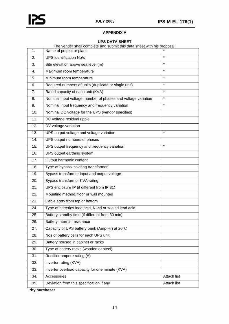
APPENDIX A
UPS DATA SHEET The vender shall complete and submit this data sheet with his proposal.
1. Name of project or plant *
2. UPS identification No/s *
3. Site elevation above sea level (m) *
4. Maximum room temperature *
5. Minimum room temperature *
6. Required numbers of units (duplicate or single unit) *
7. Rated capacity of each unit (KVA) *
8. Nominal input voltage, number of phases and voltage variation *
9. Nominal input frequency and frequency variation *
10. Nominal DC voltage for the UPS (vendor specifies)
11. DC voltage residual ripple
12. DV voltage variation
13. UPS output voltage and voltage variation *
14. UPS output numbers of phases
15. UPS output frequency and frequency variation *
16. UPS output earthing system
17. Output harmonic content
18. Type of bypass isolating transformer
19. Bypass transformer input and output voltage
20. Bypass transformer KVA rating
21. UPS enclosure IP (if different from IP 31)
22. Mounting method, floor or wall mounted
23. Cable entry from top or bottom
24. Type of batteries lead acid, Ni-cd or sealed lead acid
25. Battery standby time (if different from 30 min)
26. Battery internal resistance
27. Capacity of UPS battery bank (Amp-Hr) at 20°C
28. Nos of battery cells for each UPS unit
29. Battery housed in cabinet or racks
30. Type of battery racks (wooden or steel)
31. Rectifier ampere rating (A)
32. Inverter rating (KVA)
33. Inverter overload capacity for one minute (KVA)
34. Accessories Attach list
35. Deviation from this specification if any Attach list
*by purchaser
JULY 2003
IPS-M-EL-176(1)
15
APPENDIX B
ARRANGEMENT OF UPS SYSTEM

JULY 2003
IPS-M-EL-176(1)
16
APPENDIX C
APPLICABLE DEFINITIONS FOR THIS SPECIFICATION
The following definitions shall hold for the specification of uninterruptible power supply.
1. Float charging:
The float charging is passing an electric current through the battery bank, by applying a constant DC voltage in order to maintain the battery in the state of fully charged condition.
2. Equalize charging:
The equalize charging is passing sufficient electric current through the battery bank, by applying a controlled DC voltage in order to restore the partially or totally discharged battery in a limited time. This operation is performed automatically. The time duration is specified in this specification.
3. Boost charging:
The boost charging is passing sufficient electric current through the battery bank, by applying a controlled DC voltage in order to charge rapidly a partially or totally discharged battery in a predetermined time. This operation is performed manually. The duration for boost charging will be selected by the operator. During manual boost charging the charger and the associated battery bank will be isolated from the loads.
4. Crest factor:
Crest factor is the ratio of the peak value to the rms value of a periodic waveform.
JULY 2003
IPS-M-EL-176(1)
17
Note to Users
The IPS Standards reflect the views of the Iranian Ministry of Petroleum and are intended for use in the oil and gas production facilities, oil refineries, chemical and petrochemical plants, gas handling and processing installations and other such facilities.
IPS publications are based on internationally acceptable standards and include selections from the options stipulated in the referenced standards. They are also supplemented by additional requirements and/or modifications based on the experience acquired by the Iranian Petroleum Industry and the local market availability. The options which are not specified in the text of the standards are itemized in data sheet/s, so that, the user can select his appropriate preferences therein.
The IPS standards are therefore expected to be sufficiently flexible so that the users can adapt these standards to their requirements. However, they may not cover every requirement or diversity of conditions of each project or work.
For such cases, an addendum to IPS Standard shall be prepared by the user which elaborates the particular requirements of the user. This addendum together with the relevant IPS shall form the job specification for the specific project or work.
The users of IPS publications are therefore requested to send their views and comments, including any addendum prepared for particular cases to the Ministry of Petroleum, Standards and Research Organization. These comments and recommendations will be reviewed by the relevant technical committee and will be incorporated in the formal revision of the relevant IPS. The IPS publications are reviewed and revised approximately every five years.
IRANIAN PETROLEUM STANDARDS
No. 19, Street 14, North kheradmand Karimkhan Avenue, Tehran, Iran Tel: 66153055 88810460 Fax: 88810462 Email: [email protected]