IPoDWDM - cisco.com · CRS-MSC-40G-B (requires 3 6 x or higher)B ... With IPoDWDM, The Routing ......
73
IPoDWDM Amit Patel Technical Marketing Engineer Technical Marketing Engineer Service Provider Group
Transcript of IPoDWDM - cisco.com · CRS-MSC-40G-B (requires 3 6 x or higher)B ... With IPoDWDM, The Routing ......

IPoDWDM
Amit PatelTechnical Marketing EngineerTechnical Marketing EngineerService Provider Group
AgendaAgenda
IPoDWDM ArchitectureAdvanced IPoDWDM FeaturesIPoDWDM Management40G/100G Design Considerations
O ti l I i tOptical ImpairmentsModulation Schemes
40G/100G Deployment considerations in 10G Optical40G/100G Deployment considerations in 10G Optical networksCase Study100G - where we are today?Summary
© 2010 Cisco and/or its affiliates. All rights reserved.Presentation_ID 2

IPoDWDM Architecture
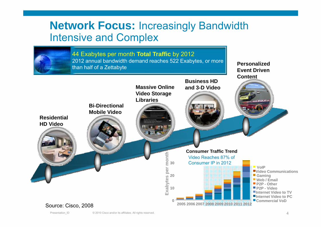
Network Focus: Increasingly Bandwidth Intensive and ComplexIntensive and Complex
44 Exabytes per month Total Traffic by 20122012 annual bandwidth demand reaches 522 Exabytes or more P li d2012 annual bandwidth demand reaches 522 Exabytes, or more than half of a Zettabyte
Massive OnlineBusiness HD and 3-D Video
Personalized Event Driven Content
Bi-Directional Mobile Video
Massive Online Video Storage Libraries
and 3-D Video
Residential HD Video
Mobile Video
30mon
th Video Reaches 87% of Consumer IP in 2012
Consumer Traffic Trend
10
20
xaby
tes
per m VoIP
Video CommunicationsGamingWeb / EmailP2P - OtherP2P - Video
© 2010 Cisco and/or its affiliates. All rights reserved.Presentation_ID 4
02005 2006 2007 2008 2009 2010 2011 2012
Ex Internet Video to TVInternet Video to PCCommercial VoD
Source: Cisco, 2008
Traffic TrendTraffic Trend
Services converging on IPServices converging on IP Peer to peerCarrier built broadcast and VoDOver the top providersVideo conferencingHigh impact data movementHigh impact data movement
Traffic is no longer predictableFlash crowds
Requires advanced protection mechanismMust meet stringent SLAs
Reduced revenue per bitEveryone wants more and more bandwidth, but not willing to pay more and more
© 2010 Cisco and/or its affiliates. All rights reserved.Presentation_ID 5

Today’s IP Network + Optical NetworkToday s IP Network + Optical Network
IP Layer Management Optical Layer Management
CoreR t
Metro Transponders converting short reach to λMetro
Router Networkreach to λNetwork
Electrical switching – OEO conversions
Electrical XC
P2P DWDM
Manual patching of
© 2010 Cisco and/or its affiliates. All rights reserved.Presentation_ID 6
Manual patching of 10G connections
Where Does This Take Us?Where Does This Take Us?
Higher band idths are needed to address this gro thHigher bandwidths are needed to address this growth:10 Gig Networks beginning to feel the strain
Cannot rely on L2/L3 aggregation: LAG 4 X 10G 40GCannot rely on L1 aggregation: DWDM ports are not unlimited
Increase wavelength capacity as soon as viable:Move to higher data rates per lambda, i.e. 40G and 100Gg p ,But must operate over existing infrastructureAnd ideally with equivalent performance to 10GRequires advanced optical modulation schemesRequires advanced optical modulation schemes
Remove all unnecessary network layers leaving only:Service layer (IP) Transport layer (DWDM)
Integrate DWDM technology on Router: IPoDWDM
© 2010 Cisco and/or its affiliates. All rights reserved.Presentation_ID 7
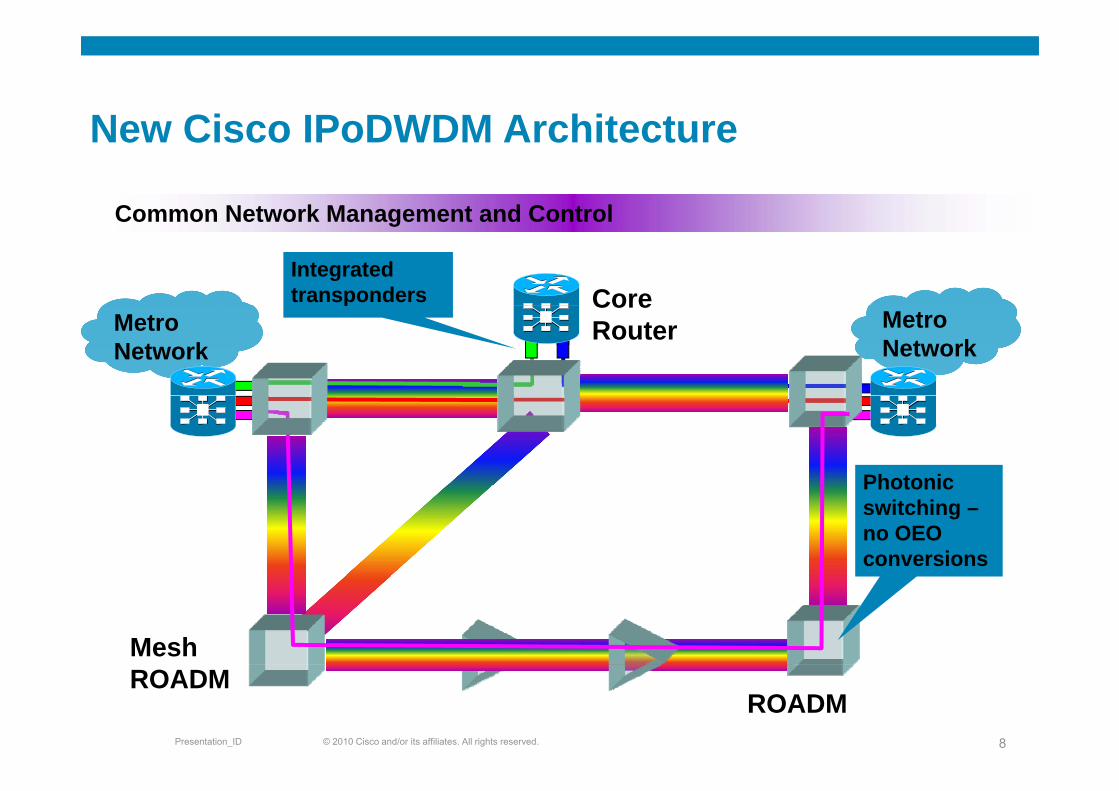
New Cisco IPoDWDM ArchitectureNew Cisco IPoDWDM Architecture
Common Network Management and Control
Integrated transponders Core
Common Network Management and Control
Metro Network
Metro Network
p CoreRouter
PhotonicPhotonic switching –no OEOconversions
Mesh
© 2010 Cisco and/or its affiliates. All rights reserved.Presentation_ID 8
ROADMROADM
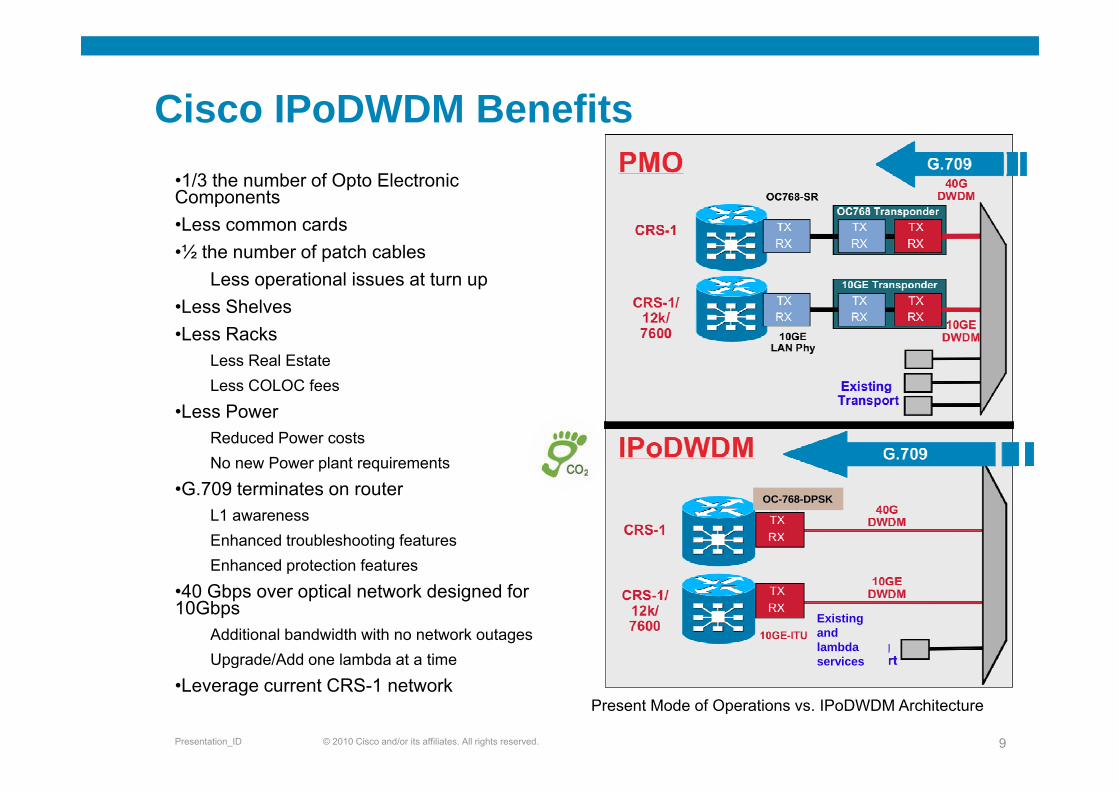
Cisco IPoDWDM Benefits •1/3 the number of Opto Electronic Components•Less common cards•½ the number of patch cables
Less operational issues at turn up•Less Shelves•Less Shelves•Less Racks
Less Real EstateLess COLOC fees
•Less PowerReduced Power costsNo new Power plant requirements
G 709 terminates on ro ter•G.709 terminates on routerL1 awarenessEnhanced troubleshooting featuresEnhanced protection features
OC-768-DPSK
•40 Gbps over optical network designed for 10Gbps
Additional bandwidth with no network outagesUpgrade/Add one lambda at a time
Existing and lambda services
© 2010 Cisco and/or its affiliates. All rights reserved.Presentation_ID 9
Upg ade/ dd o e a bda at a t e
•Leverage current CRS-1 networkservices
Present Mode of Operations vs. IPoDWDM Architecture
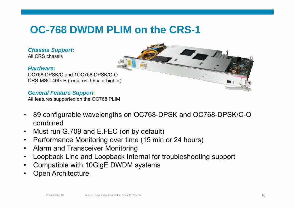
OC-768 DWDM PLIM on the CRS-1OC 768 DWDM PLIM on the CRS 1
Chassis Support:All CRS chassisAll CRS chassis
Hardware:OC768-DPSK/C and 1OC768-DPSK/C-O CRS MSC 40G B (requires 3 6 x or higher)CRS-MSC-40G-B (requires 3.6.x or higher)
General Feature Support:All features supported on the OC768 PLIM
• 89 configurable wavelengths on OC768-DPSK and OC768-DPSK/C-O combined
• Must run G.709 and E.FEC (on by default)• Performance Monitoring over time (15 min or 24 hours)• Alarm and Transceiver Monitoringg• Loopback Line and Loopback Internal for troubleshooting support• Compatible with 10GigE DWDM systems• Open Architecture
© 2010 Cisco and/or its affiliates. All rights reserved.Presentation_ID 10
Open Architecture
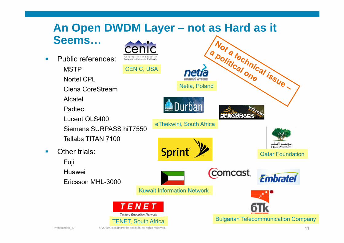
An Open DWDM Layer – not as Hard as it SeemsSeems…
Public references:MSTPNortel CPLCiena CoreStream
CENIC, USA
Netia, Poland
AlcatelPadtecLucent OLS400Siemens SURPASS hiT7550Tellabs TITAN 7100
Oth t i l
eThekwini, South Africa
Other trials:FujiHuawei
Qatar Foundation
Ericsson MHL-3000Kuwait Information Network
© 2010 Cisco and/or its affiliates. All rights reserved.Presentation_ID 11TENET, South Africa Bulgarian Telecommunication Company
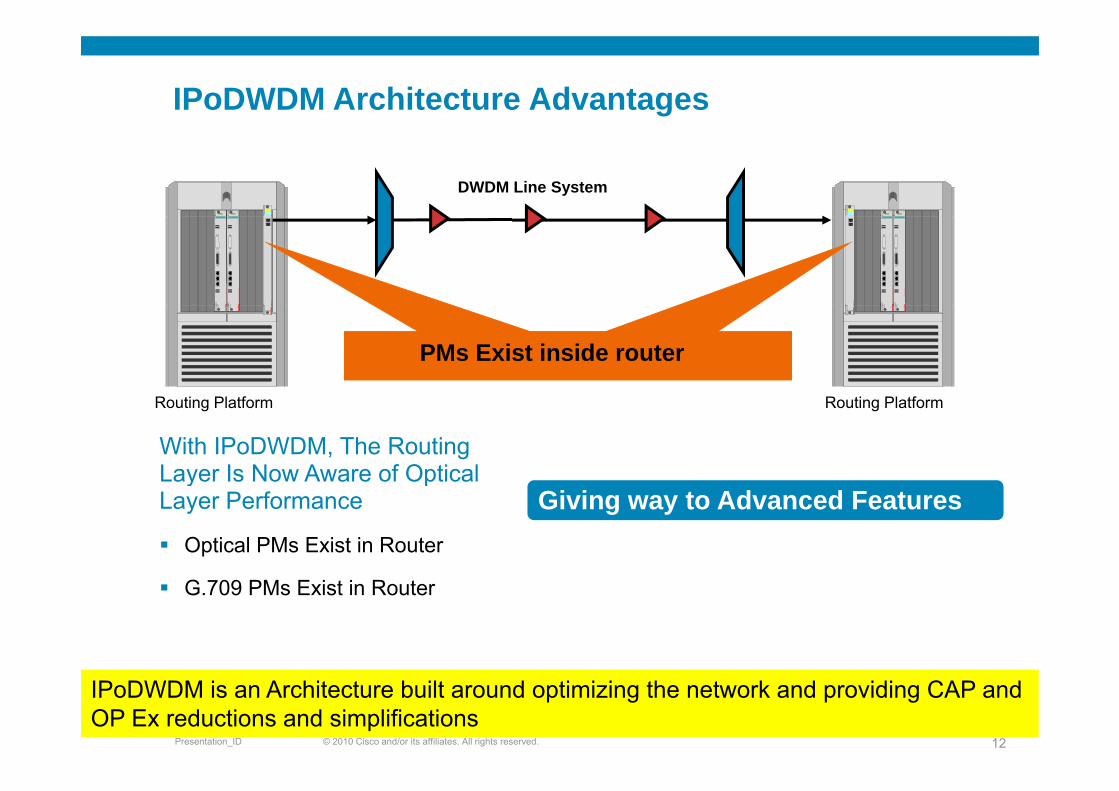
IPoDWDM Architecture Advantages
DWDM Line System
PMs Exist inside router
With IPoDWDM, The RoutingLayer Is Now Aware of Optical
Routing PlatformRouting Platform
y pLayer Performance
Optical PMs Exist in Router
Giving way to Advanced Features
G.709 PMs Exist in Router
© 2010 Cisco and/or its affiliates. All rights reserved.Presentation_ID 12
IPoDWDM is an Architecture built around optimizing the network and providing CAP and OP Ex reductions and simplifications

Advanced IPoDWDM Features
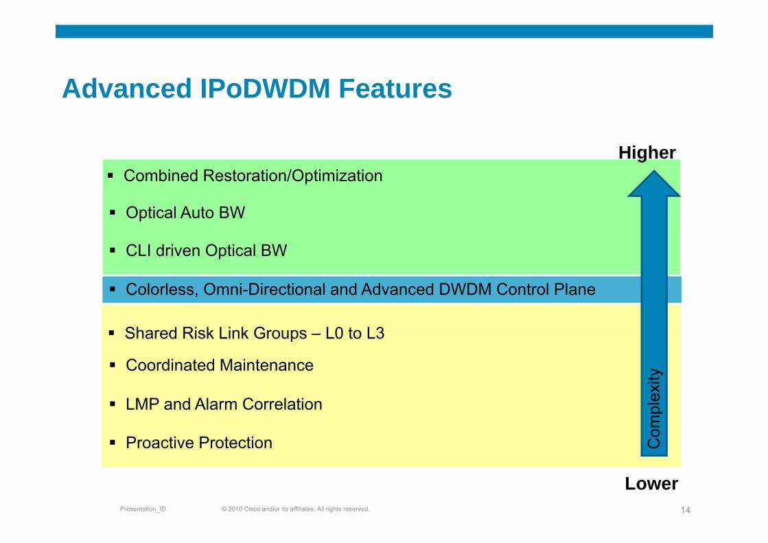
Advanced IPoDWDM FeaturesAdvanced IPoDWDM Features
Hi h
Optical Auto BW
Combined Restoration/OptimizationHigher
CLI driven Optical BW
Optical Auto BW
Shared Risk Link Groups L0 to L3
Colorless, Omni-Directional and Advanced DWDM Control Plane
Coordinated Maintenance
Shared Risk Link Groups – L0 to L3
exity
LMP and Alarm Correlation
Proactive Protection Com
ple
© 2010 Cisco and/or its affiliates. All rights reserved.Presentation_ID 14
Lower

Advanced IPoDWDM Features- Proactive ProtectionProactive Protection
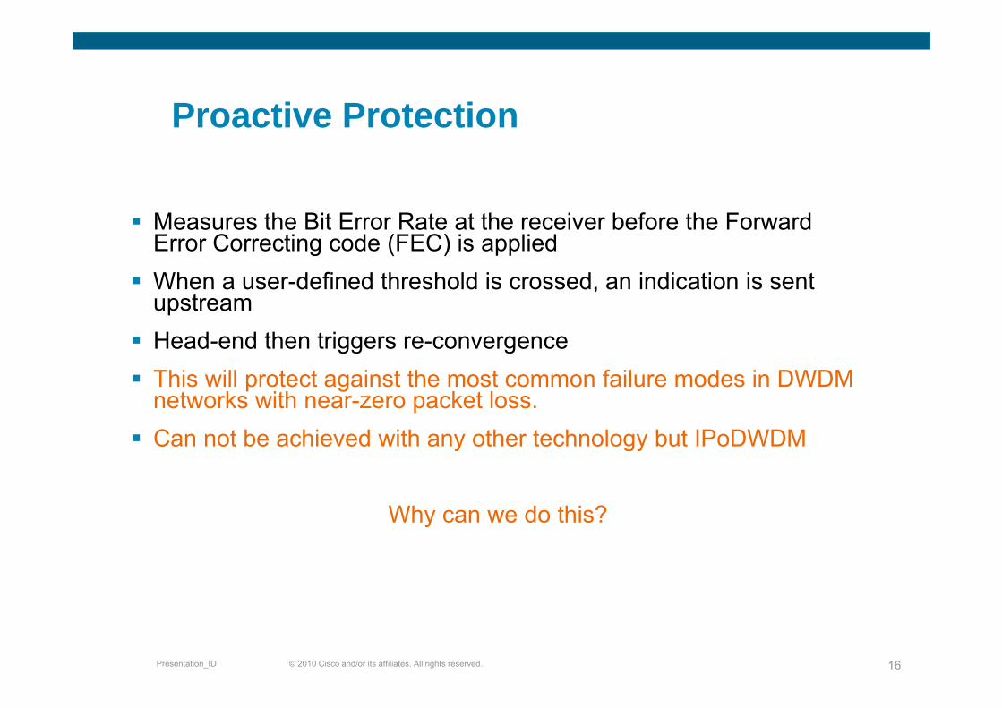
Proactive ProtectionProactive Protection
Measures the Bit Error Rate at the receiver before the Forward Error Correcting code (FEC) is appliedWh d fi d th h ld i d i di ti i tWhen a user-defined threshold is crossed, an indication is sent upstreamHead-end then triggers re-convergenceThis will protect against the most common failure modes in DWDMnetworks with near-zero packet loss.Can not be achieved with any other technology but IPoDWDMCan not be achieved with any other technology but IPoDWDM
Why can we do this?Why can we do this?
© 2010 Cisco and/or its affiliates. All rights reserved.Presentation_ID 16
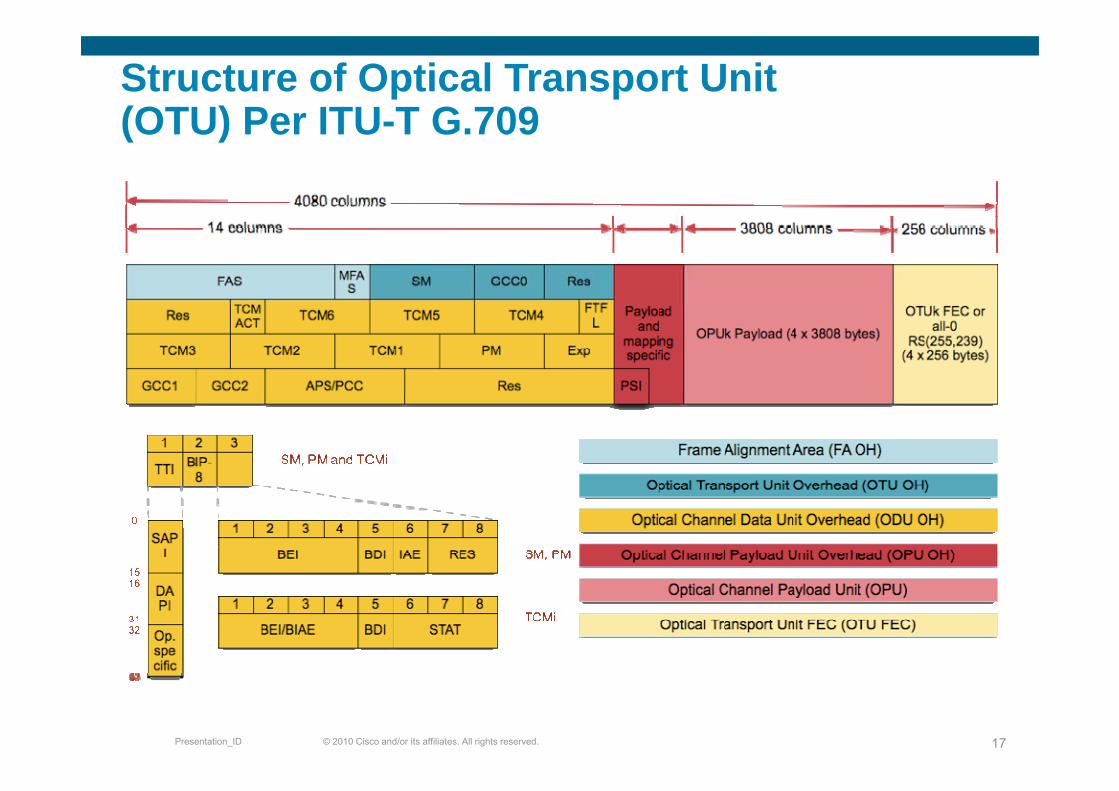
Structure of Optical Transport Unit (OTU) Per ITU-T G 709(OTU) Per ITU-T G.709
© 2010 Cisco and/or its affiliates. All rights reserved.Presentation_ID 17
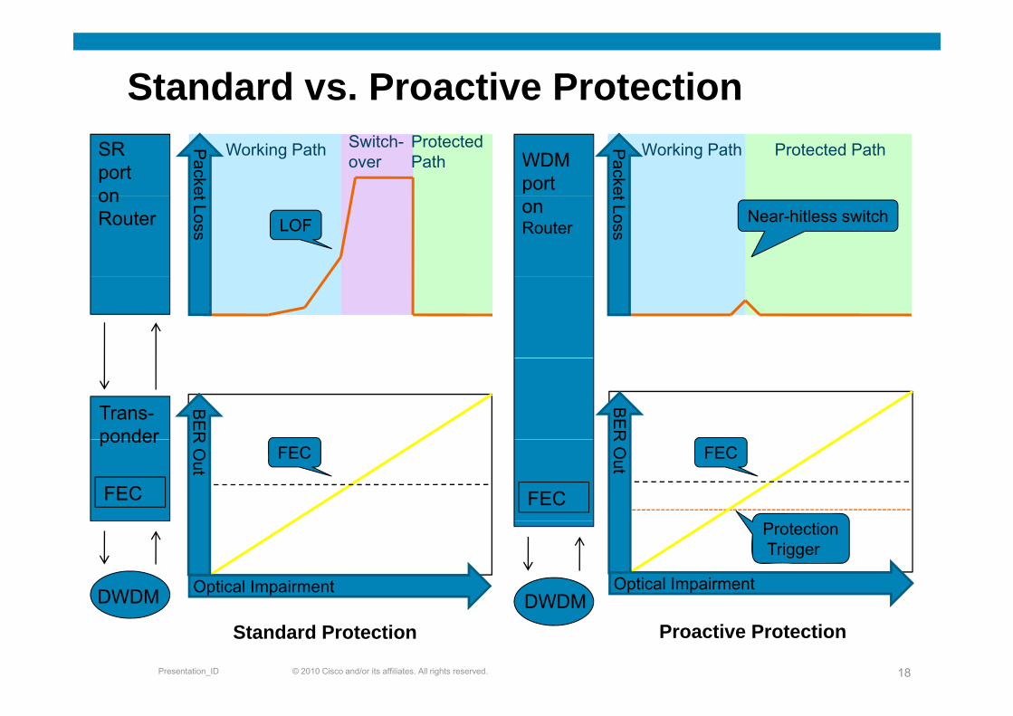
Standard vs. Proactive ProtectionSR porton
Packe
Working Path Switch-over
ProtectedPath WDM
port
Packe
Working Path Protected Path
on Router
t Loss LOFon Router
t Loss Near-hitless switch
Trans-ponder
BER
BER
ponder
FEC
R O
ut
FEC
FEC
R O
ut FEC
DWDM Optical ImpairmentDWDM
ProtectionTrigger
Optical Impairment
© 2010 Cisco and/or its affiliates. All rights reserved.Presentation_ID 18
DWDM
Standard ProtectionDWDM
Proactive Protection
Maintenance mode for DWDM interfaceMaintenance mode for DWDM interface
Proactive protection is also used to switch traffic away due to aProactive protection is also used to switch traffic away due to a maintenance activity
When the state of a DWDM port is put in out of service – maint(OOS MT) b t t l ( CTC) ll ( i CLI)(OOS-MT), by a mgmt tool (e.g., CTC) or manually (via CLI), proactive protection will be used
Proactive protection will bidirectionally switch away from the line f th t i t i OOS MT d It ill bl fonce one of the ports is put in OOS-MT mode. It will re-enable use of
the line only when both ends are back in service
Note: this behavior is active irrespective if proactive protection is enabled or disabled – the “no enable” command disables automatic triggering of protection but not maintenance triggers
© 2010 Cisco and/or its affiliates. All rights reserved.Presentation_ID 19
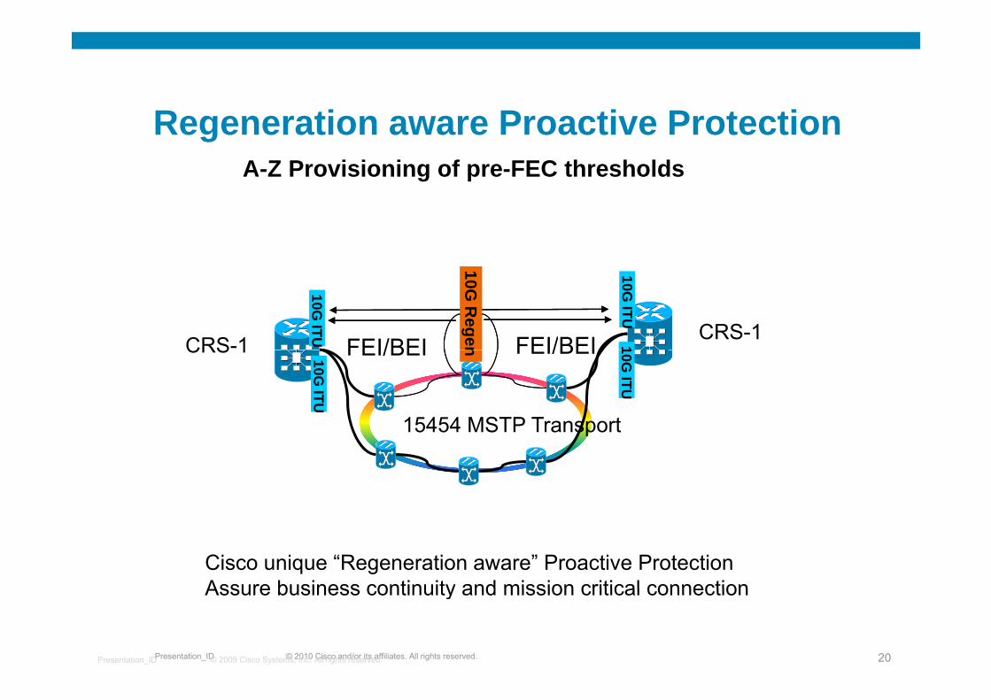
R ti P ti P t tiRegeneration aware Proactive ProtectionA-Z Provisioning of pre-FEC thresholds
10G ITU
10G R
egenFEI/BEI FEI/BEI10G
ITU1CRS-1 CRS-1nFEI/BEI FEI/BEI10G
ITU
10G ITU
15454 MSTP Transport
CRS 1
15454 MSTP Transport
Cisco unique “Regeneration aware” Proactive ProtectionAssure business continuity and mission critical connection
© 2010 Cisco and/or its affiliates. All rights reserved.Presentation_ID 20© 2009 Cisco Systems, Inc. All rights reserved.Presentation_ID
Assure business continuity and mission critical connection
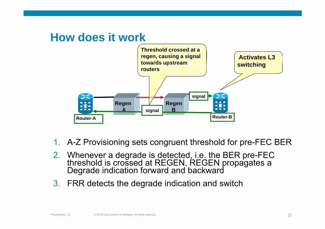
How does it workHow does it workThreshold crossed at a regen, causing a signal towards upstream
Activates L3 it hitowards upstream
routersswitching
RegenA
RegenB
signal
signal
1 A Z Pro isioning sets congr ent threshold for pre FEC BER
Router-A Router-B
1. A-Z Provisioning sets congruent threshold for pre-FEC BER2. Whenever a degrade is detected, i.e. the BER pre-FEC
threshold is crossed at REGEN, REGEN propagates a , p p gDegrade indication forward and backward
3. FRR detects the degrade indication and switch
© 2010 Cisco and/or its affiliates. All rights reserved.Presentation_ID 21
Advanced IPoDWDM Features- Shared Risk Link Groups (SRLG)Shared Risk Link Groups (SRLG)
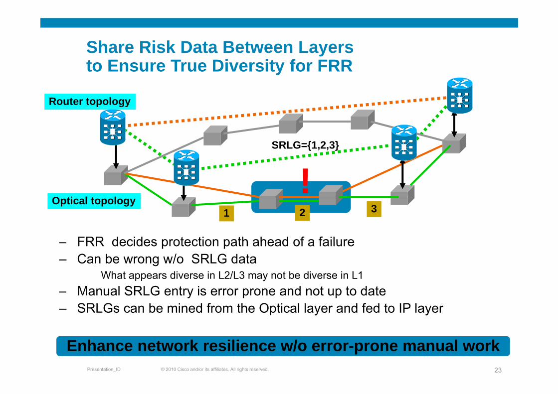
Share Risk Data Between Layersto Ensure True Diversity for FRRto Ensure True Diversity for FRR
Router topology
SRLG={1,2,3}
!O ti l t l
FRR decides protection path ahead of a failure
1 2 3Optical topology
– FRR decides protection path ahead of a failure– Can be wrong w/o SRLG data
What appears diverse in L2/L3 may not be diverse in L1M l SRLG t i d t t d t– Manual SRLG entry is error prone and not up to date
– SRLGs can be mined from the Optical layer and fed to IP layer
© 2010 Cisco and/or its affiliates. All rights reserved.Presentation_ID 23
Enhance network resilience w/o error-prone manual work
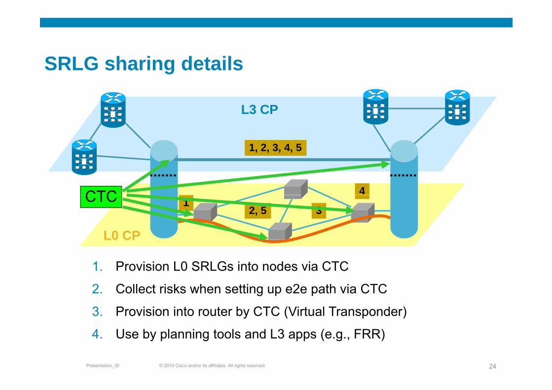
SRLG sharing detailsSRLG sharing details
L3 CPL3 CP
1, 2, 3, 4, 5
4
1, 2, 3, 4, 5
CTC 12, 5 3
L0 CP
CTC
1. Provision L0 SRLGs into nodes via CTC
L0 CP
2. Collect risks when setting up e2e path via CTC
3. Provision into router by CTC (Virtual Transponder)
© 2010 Cisco and/or its affiliates. All rights reserved.Presentation_ID 24
4. Use by planning tools and L3 apps (e.g., FRR)

IPoDWDM Management
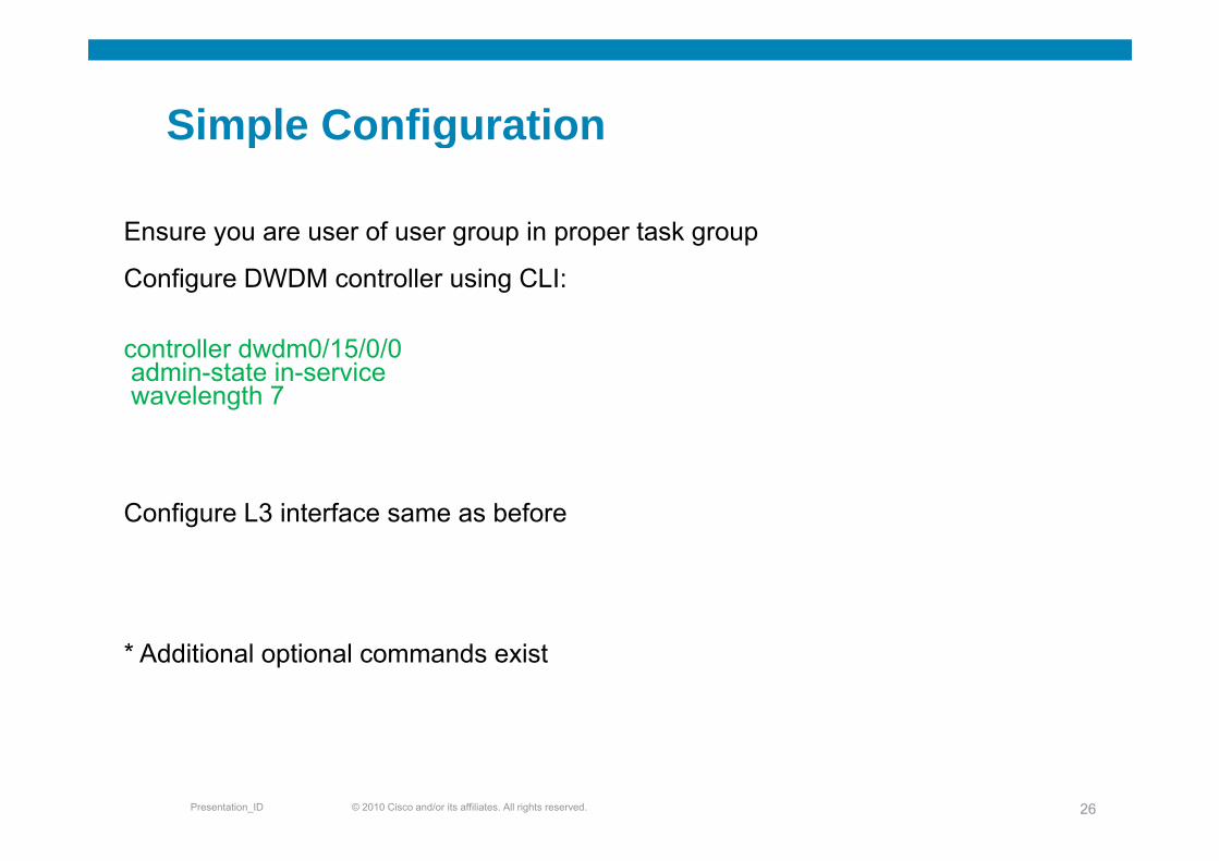
Simple ConfigurationSimple Configuration
Ensure you are user of user group in proper task groupEnsure you are user of user group in proper task group
Configure DWDM controller using CLI:
controller dwdm0/15/0/0admin-state in-servicewavelength 7
Configure L3 interface same as before
* Additional optional commands exist
© 2010 Cisco and/or its affiliates. All rights reserved.Presentation_ID 26
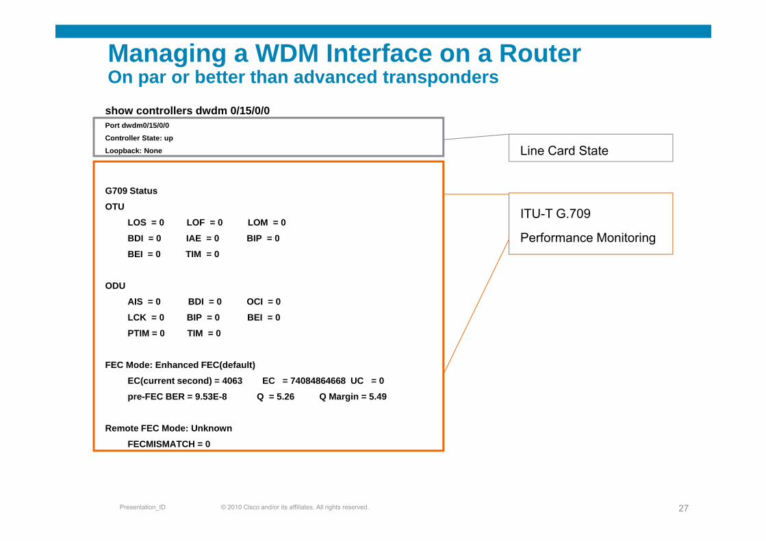
Managing a WDM Interface on a RouterOn par or better than advanced transpondersp p
Li C d St t
show controllers dwdm 0/15/0/0 Port dwdm0/15/0/0
Controller State: up
ITU T G 709
Line Card StateLoopback: None
G709 Status
OTU ITU-T G.709
Performance Monitoring
OTU
LOS = 0 LOF = 0 LOM = 0
BDI = 0 IAE = 0 BIP = 0
BEI = 0 TIM = 0
ODU
AIS = 0 BDI = 0 OCI = 0
LCK = 0 BIP = 0 BEI = 0
PTIM = 0 TIM = 0PTIM = 0 TIM = 0
FEC Mode: Enhanced FEC(default)
EC(current second) = 4063 EC = 74084864668 UC = 0
FEC BER 9 53E 8 Q 5 26 Q M i 5 49pre-FEC BER = 9.53E-8 Q = 5.26 Q Margin = 5.49
Remote FEC Mode: Unknown
FECMISMATCH = 0
© 2010 Cisco and/or its affiliates. All rights reserved.Presentation_ID 27
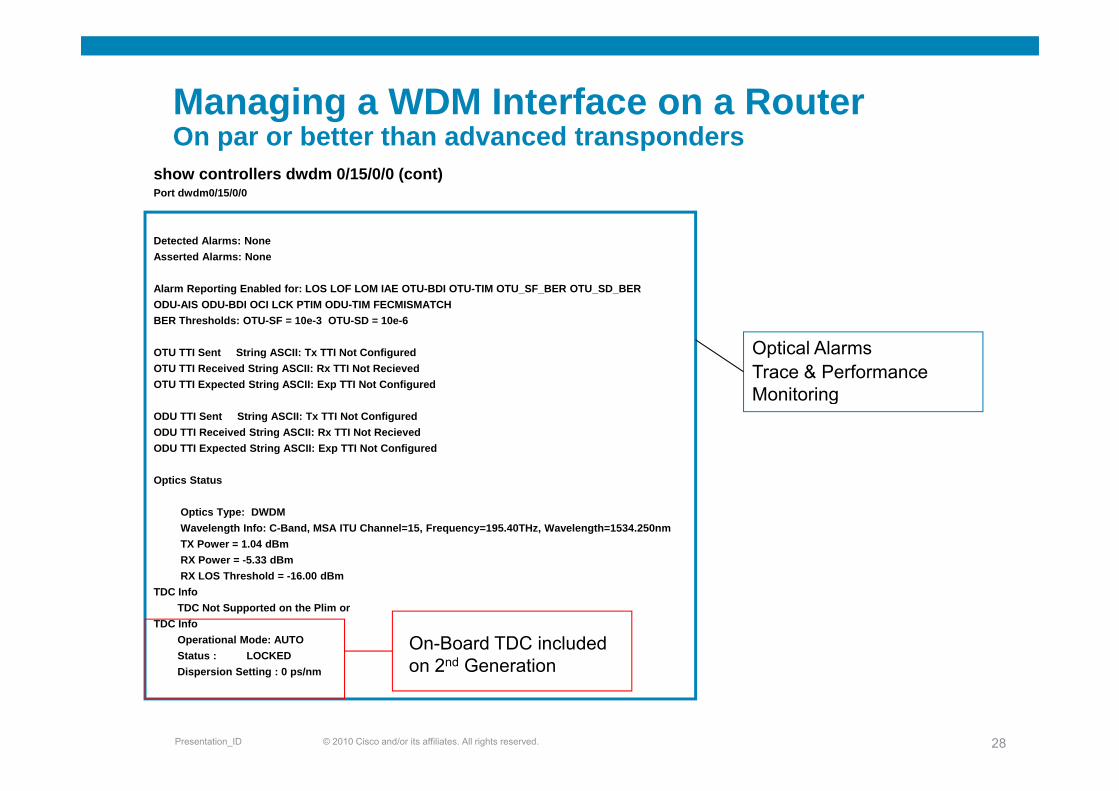
Managing a WDM Interface on a RouterOOn par or better than advanced transponders
show controllers dwdm 0/15/0/0 (cont)Port dwdm0/15/0/0
Detected Alarms: NoneAsserted Alarms: None
Alarm Reporting Enabled for: LOS LOF LOM IAE OTU-BDI OTU-TIM OTU_SF_BER OTU_SD_BER ODU-AIS ODU-BDI OCI LCK PTIM ODU-TIM FECMISMATCH
Optical Alarms Trace & Performance Monitoring
ODU-AIS ODU-BDI OCI LCK PTIM ODU-TIM FECMISMATCH BER Thresholds: OTU-SF = 10e-3 OTU-SD = 10e-6
OTU TTI Sent String ASCII: Tx TTI Not Configured OTU TTI Received String ASCII: Rx TTI Not Recieved OTU TTI Expected String ASCII: Exp TTI Not Configured
MonitoringODU TTI Sent String ASCII: Tx TTI Not Configured ODU TTI Received String ASCII: Rx TTI Not Recieved ODU TTI Expected String ASCII: Exp TTI Not Configured
Optics Status p
Optics Type: DWDMWavelength Info: C-Band, MSA ITU Channel=15, Frequency=195.40THz, Wavelength=1534.250nm TX Power = 1.04 dBm RX Power = -5.33 dBm RX LOS Threshold = 16 00 dBm
On-Board TDC included on 2nd Generation
RX LOS Threshold = -16.00 dBm TDC Info
TDC Not Supported on the Plim orTDC Info
Operational Mode: AUTOStatus : LOCKED
© 2010 Cisco and/or its affiliates. All rights reserved.Presentation_ID 28
on 2nd GenerationDispersion Setting : 0 ps/nm
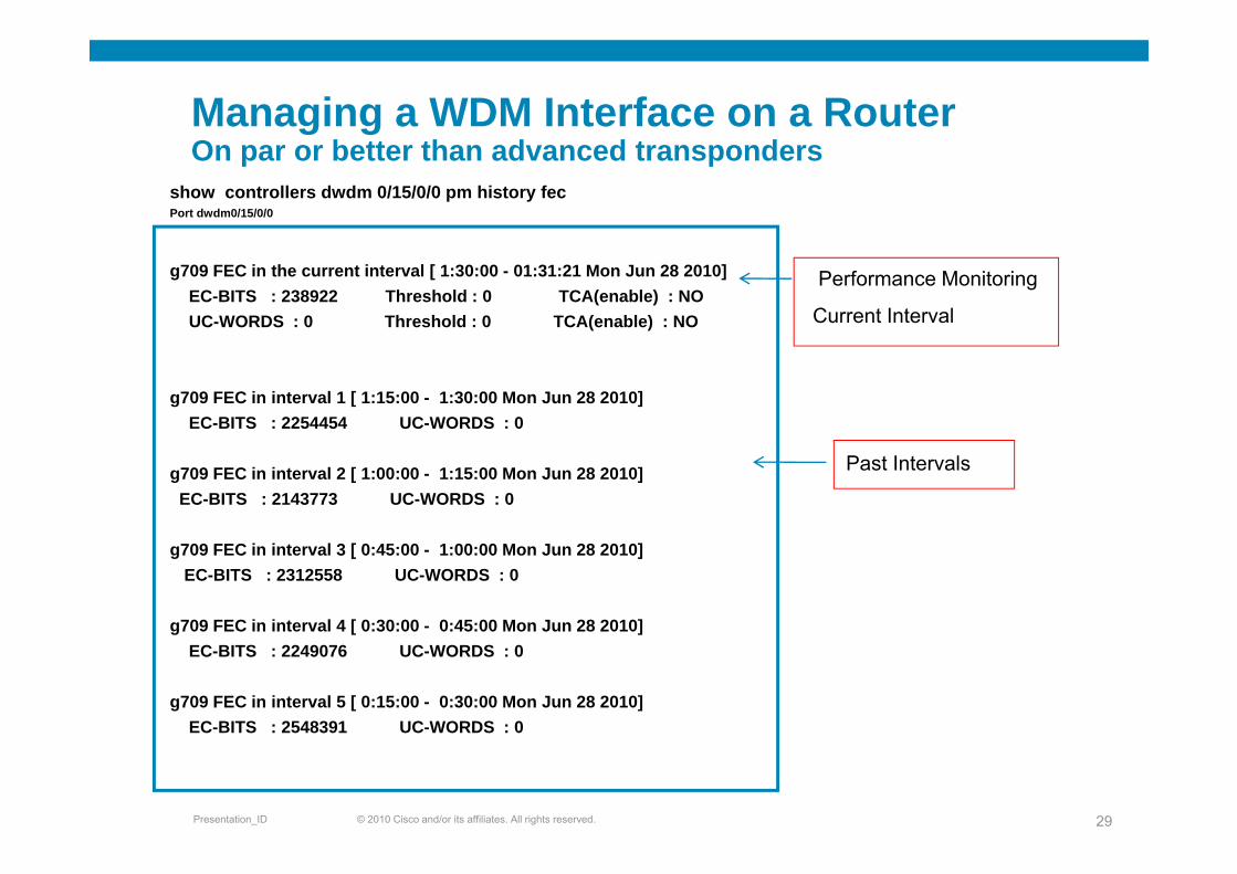
Managing a WDM Interface on a RouterOOn par or better than advanced transponders
show controllers dwdm 0/15/0/0 pm history fecPort dwdm0/15/0/0
Performance Monitoring
Current Interval
g709 FEC in the current interval [ 1:30:00 - 01:31:21 Mon Jun 28 2010]EC-BITS : 238922 Threshold : 0 TCA(enable) : NOUC-WORDS : 0 Threshold : 0 TCA(enable) : NO
g709 FEC in interval 1 [ 1:15:00 - 1:30:00 Mon Jun 28 2010]EC-BITS : 2254454 UC-WORDS : 0
Past Intervalsg709 FEC in interval 2 [ 1:00:00 - 1:15:00 Mon Jun 28 2010]EC-BITS : 2143773 UC-WORDS : 0
g709 FEC in interval 3 [ 0:45:00 - 1:00:00 Mon Jun 28 2010]EC-BITS : 2312558 UC-WORDS : 0
g709 FEC in interval 4 [ 0:30:00 - 0:45:00 Mon Jun 28 2010]EC-BITS : 2249076 UC-WORDS : 0
g709 FEC in interval 5 [ 0:15:00 - 0:30:00 Mon Jun 28 2010]EC-BITS : 2548391 UC-WORDS : 0
© 2010 Cisco and/or its affiliates. All rights reserved.Presentation_ID 29
Managing the SP “walls”: Virtual g gTransponders
The major objection against IPoDWDM: theThe major objection against IPoDWDM: the transport people want to manage “their” transponderstransponders
The data/network people don’t want the transport people to touch “their” routersp p p
Virtual Transponders address this issue
© 2010 Cisco and/or its affiliates. All rights reserved.Presentation_ID 30
What does the Virtual Transponder do?What does the Virtual Transponder do?
Exposes the DWDM aspects of an IPoDWDM interfaceExposes the DWDM aspects of an IPoDWDM interface
Integrate into DWDM EMS using XML
Allows for segmented management of the transmission and IP networksand IP networks
© 2010 Cisco and/or its affiliates. All rights reserved.Presentation_ID 31
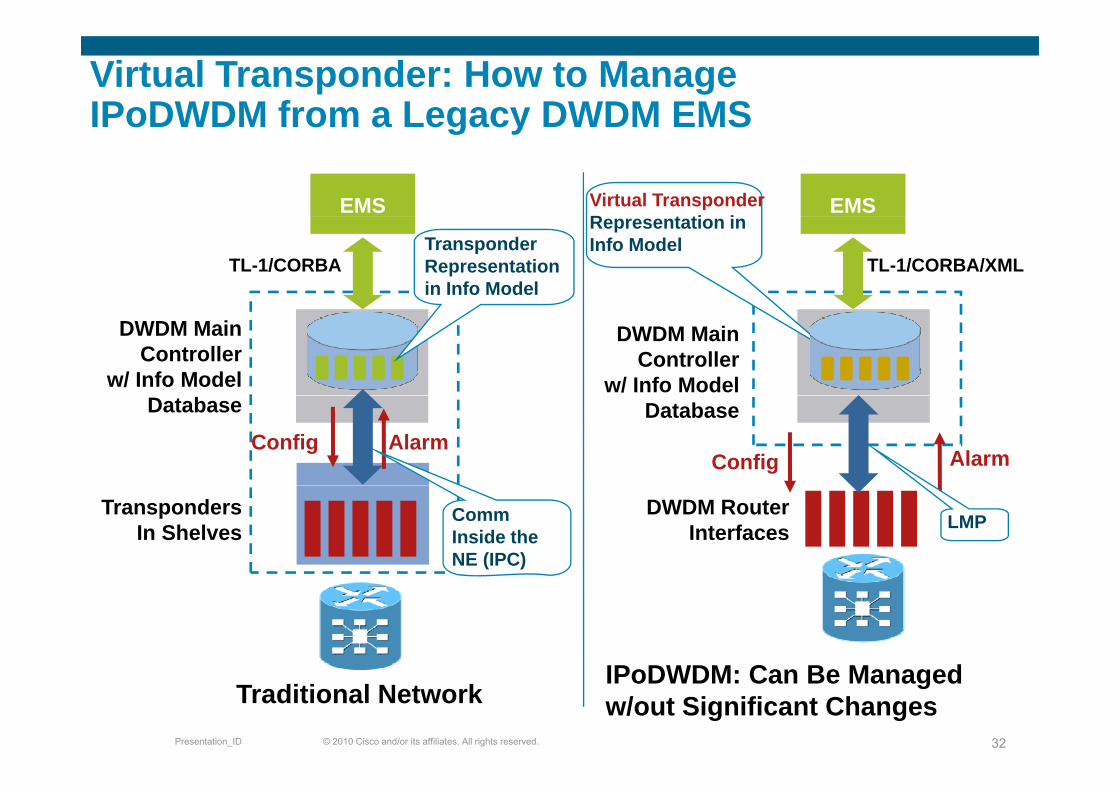
Virtual Transponder: How to Manage IPoDWDM from a Legacy DWDM EMSIPoDWDM from a Legacy DWDM EMS
EMS EMSVirtual Transponder R t ti i
TL-1/CORBATransponder Representation in Info Model
TL-1/CORBA/XML
Representation in Info Model
DWDM Main Controller
w/ Info Model
DWDM Main Controller
w/ Info Model
Alarm
Database
ConfigAlarmConfig
Database
TranspondersIn Shelves
Comm Inside the NE (IPC)
DWDM Router Interfaces LMP
IP DWDM C B M d
© 2010 Cisco and/or its affiliates. All rights reserved.Presentation_ID 32
Traditional NetworkIPoDWDM: Can Be Managed w/out Significant Changes
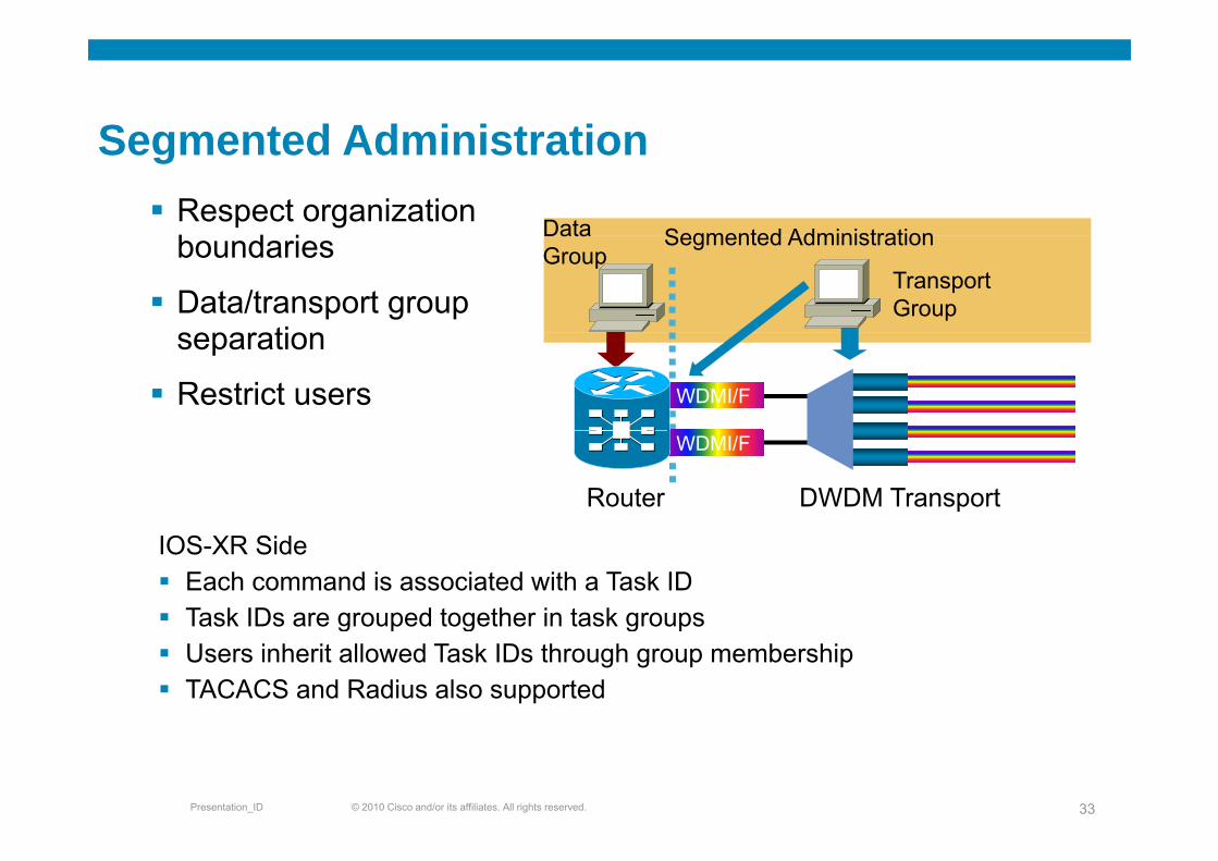
Segmented AdministrationRespect organization b d i Segmented AdministrationData
Segmented Administration
boundaries
Data/transport group separation
Segmented AdministrationData Group
Transport Group
separation
Restrict users rule based access control
WDMI/F
rule-based access control
DWDM TransportRouter
WDMI/F
IOS-XR SideEach command is associated with a Task ID Task IDs are grouped together in task groupsTask IDs are grouped together in task groupsUsers inherit allowed Task IDs through group membershipTACACS and Radius also supported
© 2010 Cisco and/or its affiliates. All rights reserved.Presentation_ID 33
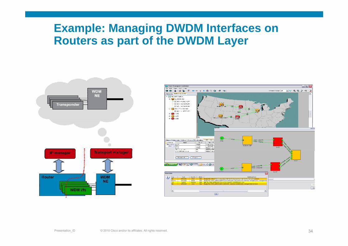
Example: Managing DWDM Interfaces on Routers as part of the DWDM LayerRouters as part of the DWDM Layer
© 2010 Cisco and/or its affiliates. All rights reserved.Presentation_ID 34
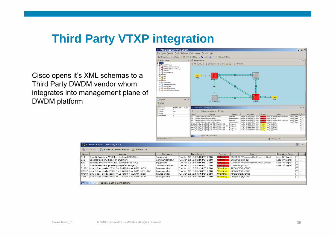
Third Party VTXP integrationThird Party VTXP integration
Cisco opens it’s XML schemas to a Third Party DWDM vendor whom integrates into management plane ofintegrates into management plane of DWDM platform
© 2010 Cisco and/or its affiliates. All rights reserved.Presentation_ID 35

40G/ 100G Design Considerations
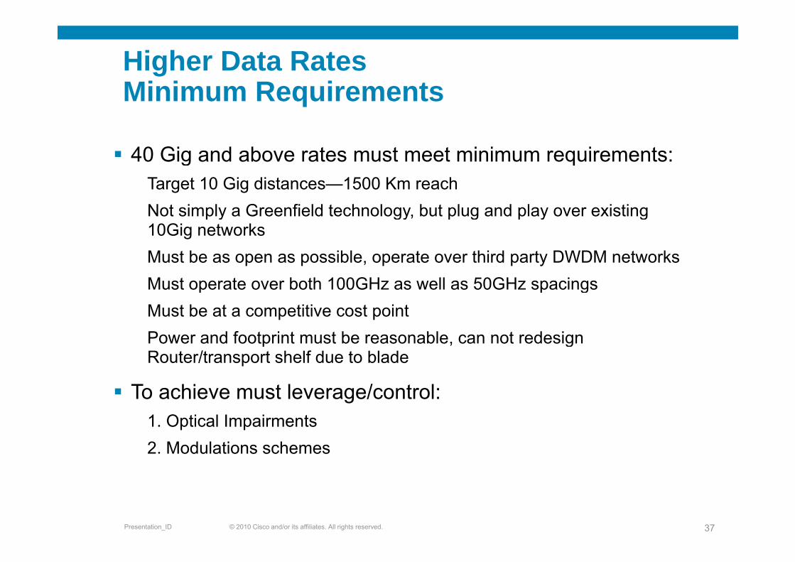
Higher Data RatesMinimum RequirementsMinimum Requirements
40 Gig and above rates must meet minimum requirements:40 Gig and above rates must meet minimum requirements:Target 10 Gig distances—1500 Km reachNot simply a Greenfield technology, but plug and play over existing p y gy, p g p y g10Gig networksMust be as open as possible, operate over third party DWDM networksMust operate over both 100GHz as well as 50GHz spacingsMust operate over both 100GHz as well as 50GHz spacingsMust be at a competitive cost pointPower and footprint must be reasonable, can not redesign p , gRouter/transport shelf due to blade
To achieve must leverage/control:1. Optical Impairments2. Modulations schemes
© 2010 Cisco and/or its affiliates. All rights reserved.Presentation_ID 37
Optical Impairments
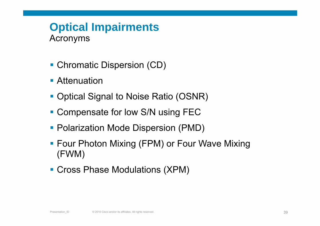
Optical ImpairmentsAAcronyms
Ch ti Di i (CD)Chromatic Dispersion (CD)
Attenuation
Optical Signal to Noise Ratio (OSNR)
Compensate for low S/N using FECCompensate for low S/N using FEC
Polarization Mode Dispersion (PMD)
Four Photon Mixing (FPM) or Four Wave Mixing (FWM)
Cross Phase Modulations (XPM)
© 2010 Cisco and/or its affiliates. All rights reserved.Presentation_ID 39
Optical ImpairmentsOptical Impairments
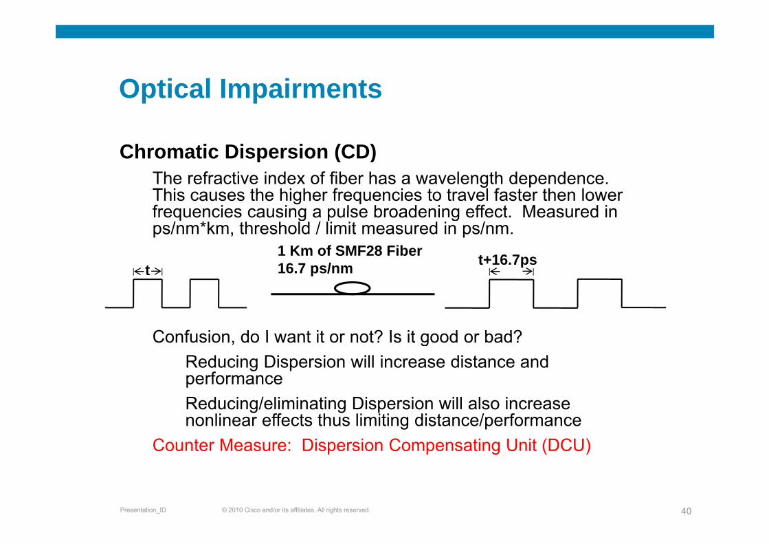
Chromatic Dispersion (CD)Chromatic Dispersion (CD)The refractive index of fiber has a wavelength dependence. This causes the higher frequencies to travel faster then lower frequencies causing a pulse broadening effect Measured infrequencies causing a pulse broadening effect. Measured in ps/nm*km, threshold / limit measured in ps/nm.
tt+16.7ps1 Km of SMF28 Fiber
16.7 ps/nm
Confusion do I want it or not? Is it good or bad?
t 16.7 ps/nm
Confusion, do I want it or not? Is it good or bad?Reducing Dispersion will increase distance and performanceReducing/eliminating Dispersion will also increase nonlinear effects thus limiting distance/performance
Counter Measure: Dispersion Compensating Unit (DCU)
© 2010 Cisco and/or its affiliates. All rights reserved.Presentation_ID 40
Optical ImpairmentsOptical Impairments
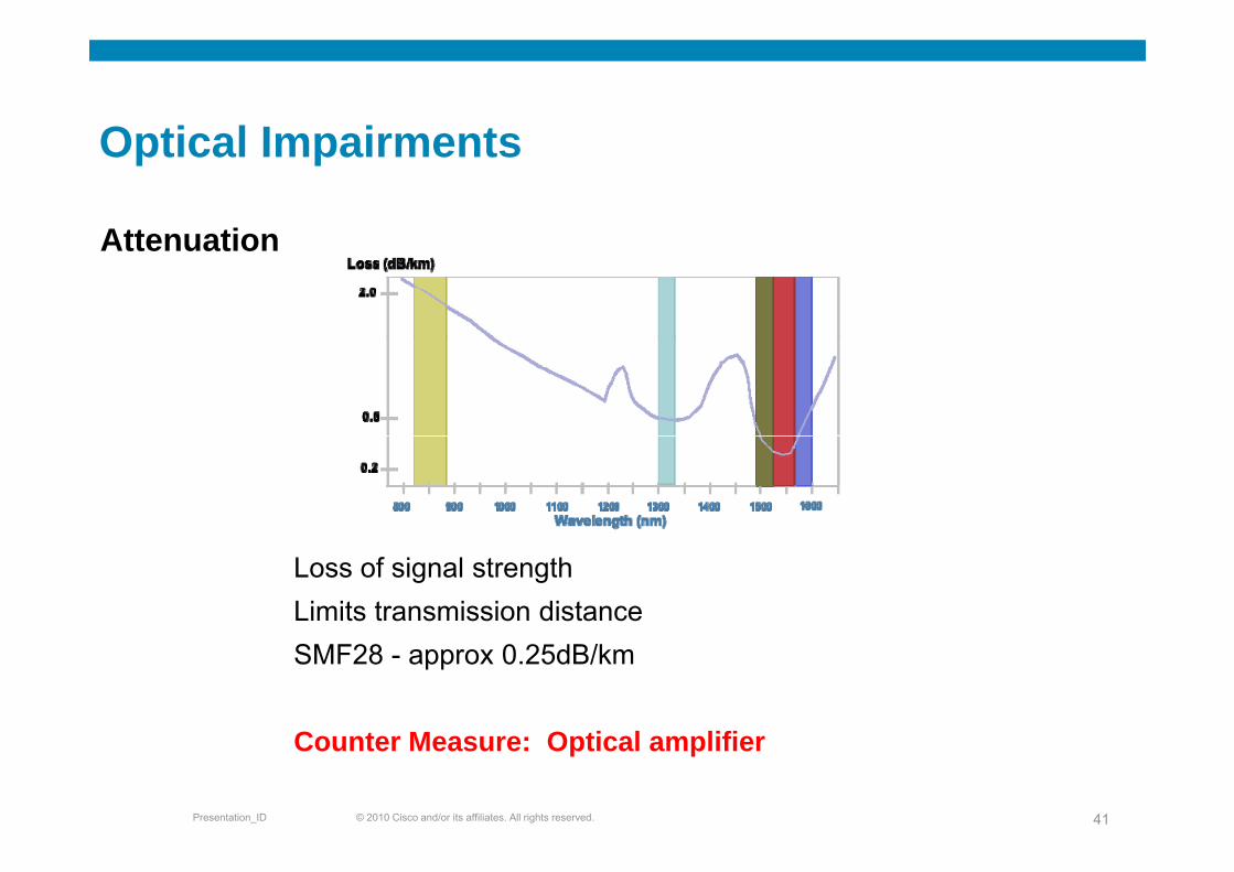
AttenuationAttenuation
Loss of signal strength Limits transmission distanceSMF28 - approx 0.25dB/km
C t M O ti l lifi
© 2010 Cisco and/or its affiliates. All rights reserved.Presentation_ID 41
Counter Measure: Optical amplifier
Optical ImpairmentsOptical Impairments
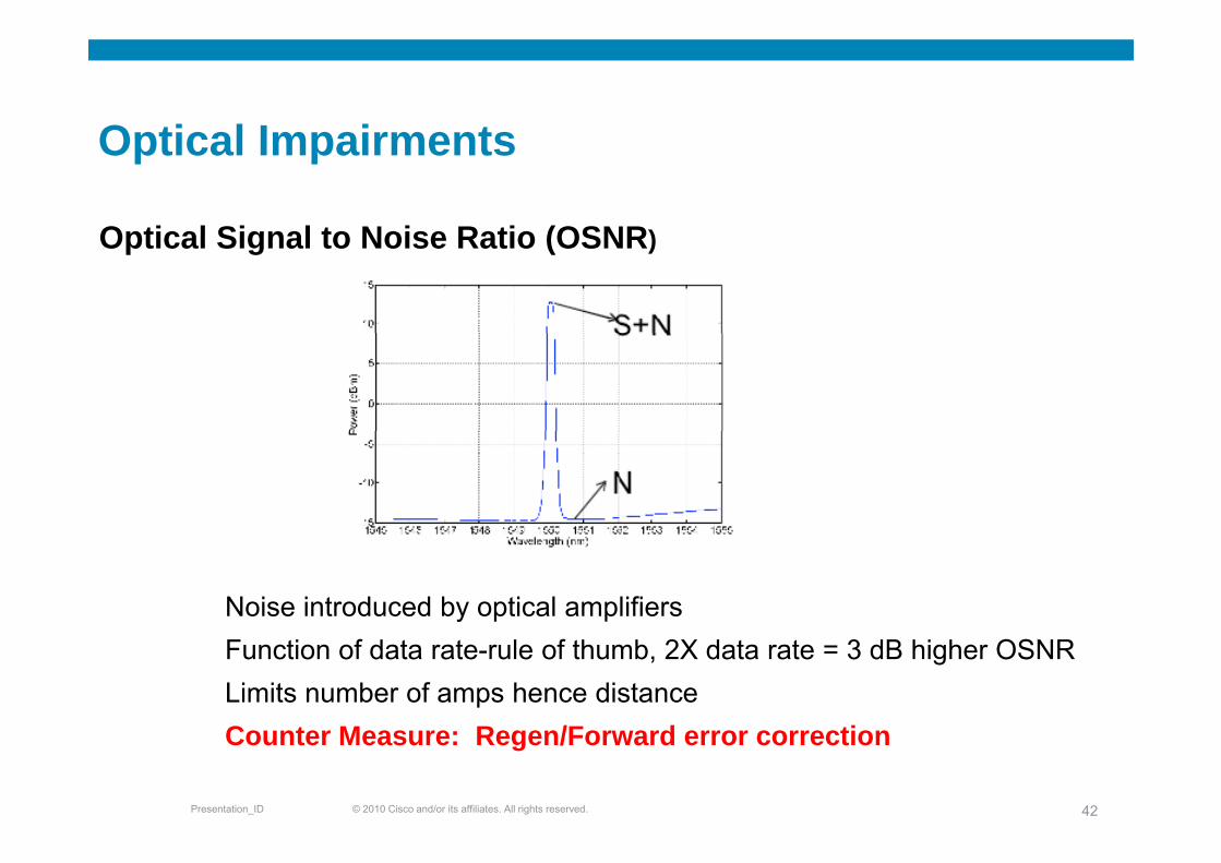
Optical Signal to Noise Ratio (OSNR)Optical Signal to Noise Ratio (OSNR)
Noise introduced by optical amplifiersFunction of data rate-rule of thumb, 2X data rate = 3 dB higher OSNRLimits number of amps hence distanceC M R /F d i
© 2010 Cisco and/or its affiliates. All rights reserved.Presentation_ID 42
Counter Measure: Regen/Forward error correction

Optical ImpairmentsCompensate for low S/N using FEC
1
0
Compensate for low S/N using FEC
FEC extends reach and
–4
–3
–2–1
Raw Channel BER=1.5e-3FEC extends reach and design flexibility, at “silicon cost”
G 709 t d d i
BER
)
–7
–6–5
4G.709 standard improves OSNR tolerance by 6.2 dB (at 10–15 BER)
Log
(B
–10–9
–8Offers intrinsic performance monitoring (error statistics)
Higher gains (8 4dB) possible
14–13
–12
–11 UncodedNo FEC
EFEC=8.4 dB
Higher gains (8.4dB) possible by enhanced FEC (with same G.709 overhead)
4 5 6 7 8 9 10 11 12 13 14 15–15
–14
S/N (dB)
EFEC 8.4 dBFEC=6.2 dB
© 2010 Cisco and/or its affiliates. All rights reserved.Presentation_ID 43
Benefit: FEC/EFEC Extends Reach and Offers 10–15 BER
Optical ImpairmentsOptical Impairments
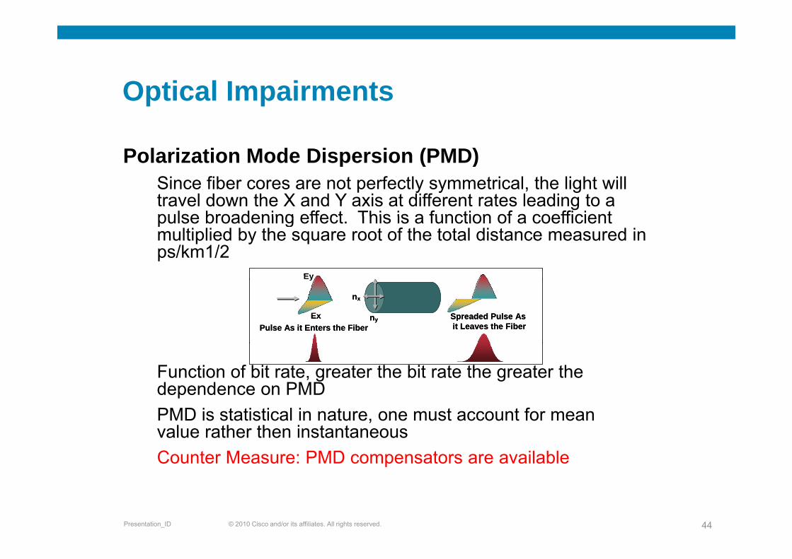
Polarization Mode Dispersion (PMD)Polarization Mode Dispersion (PMD)Since fiber cores are not perfectly symmetrical, the light will travel down the X and Y axis at different rates leading to a pulse broadening effect This is a function of a coefficientpulse broadening effect. This is a function of a coefficient multiplied by the square root of the total distance measured in ps/km1/2
EyEy
nx
nyEx
y
Pulse As it Enters the FiberSpreaded Pulse As it Leaves the Fiber
nx
nyEx
y
Pulse As it Enters the FiberSpreaded Pulse As it Leaves the Fiber
Function of bit rate, greater the bit rate the greater the dependence on PMDPMD is statistical in nature, one must account for mean value rather then instantaneousCounter Measure: PMD compensators are available
© 2010 Cisco and/or its affiliates. All rights reserved.Presentation_ID 44
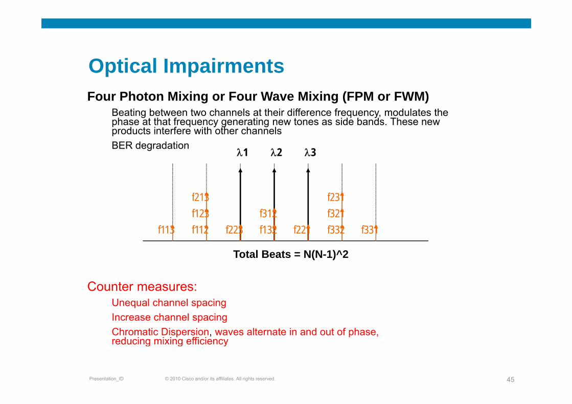
Optical ImpairmentsOptical ImpairmentsFour Photon Mixing or Four Wave Mixing (FPM or FWM)
B ti b t t h l t th i diff f d l t thBeating between two channels at their difference frequency, modulates the phase at that frequency generating new tones as side bands. These new products interfere with other channelsBER degradation
λ1 λ2 λ3
f213 f231
f113 f112f123
f223 f132f312
f221 f332f321
f331
Counter measures:
Total Beats = N(N-1)^2
Unequal channel spacingIncrease channel spacingChromatic Dispersion, waves alternate in and out of phase, reducing mixing efficiency
© 2010 Cisco and/or its affiliates. All rights reserved.Presentation_ID 45
reducing mixing efficiency
Optical ImpairmentsOptical Impairments
C Ph M d l ti (XPM)Cross Phase Modulation (XPM)This arises due to the weak dependence of the refractive index on intensity: n=n0 + n2*I Here the nonlinear refractiveindex on intensity: n n0 + n2 I. Here the nonlinear refractive index modulates one of the carriers onto the other. Pulse broadening gets exaggerated with Chromatic Di iDispersion
Counter measures:Chromatic Dispersion, the group velocity causes the interfering pulse to walk thru the other Larger spacing between carriersLarger spacing between carriers
© 2010 Cisco and/or its affiliates. All rights reserved.Presentation_ID 46

Modulation Schemes
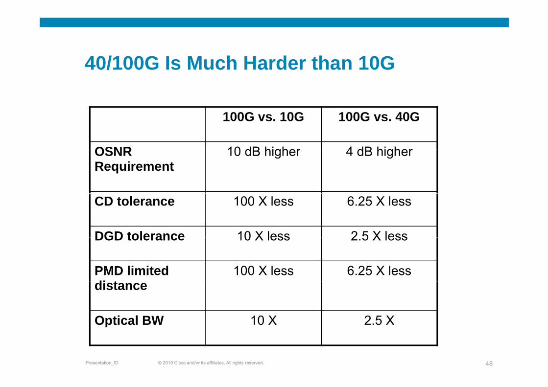
40/100G Is Much Harder than 10G40/100G Is Much Harder than 10G
100G vs. 10G 100G vs. 40G
OSNR 10 dB higher 4 dB higherOSNR Requirement
10 dB higher 4 dB higher
CD tolerance 100 X less 6.25 X less
DGD tolerance 10 X less 2 5 X lessDGD tolerance 10 X less 2.5 X less
PMD limited di t
100 X less 6.25 X lessdistance
Optical BW 10 X 2.5 X
© 2010 Cisco and/or its affiliates. All rights reserved.Presentation_ID 48
p
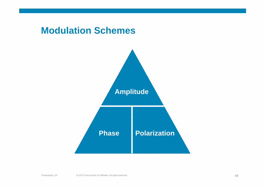
Modulation SchemesModulation Schemes
AmplitudeAmplitude
Phase Polarization
© 2010 Cisco and/or its affiliates. All rights reserved.Presentation_ID 49
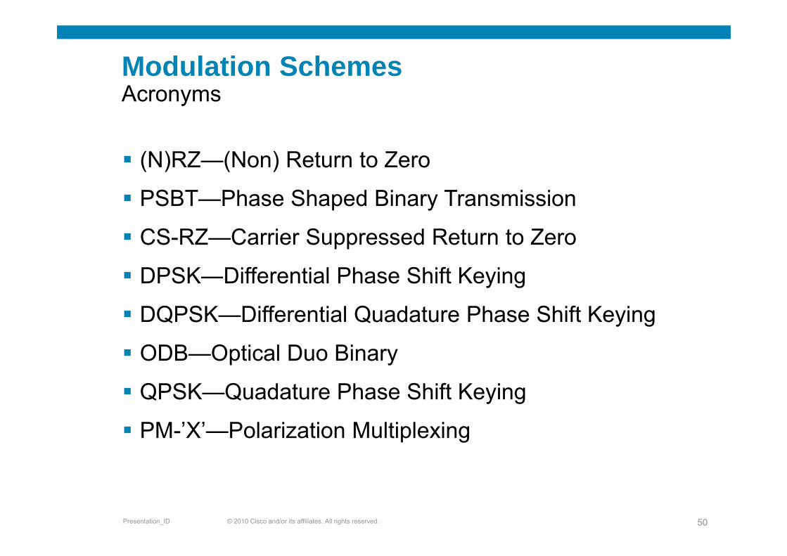
Modulation SchemesAAcronyms
(N)RZ (N ) R t t Z(N)RZ—(Non) Return to Zero
PSBT—Phase Shaped Binary Transmission
CS-RZ—Carrier Suppressed Return to Zero
DPSK—Differential Phase Shift KeyingDPSK—Differential Phase Shift Keying
DQPSK—Differential Quadature Phase Shift Keying
ODB—Optical Duo Binary
QPSK—Quadature Phase Shift Keying
PM-’X’—Polarization Multiplexing
© 2010 Cisco and/or its affiliates. All rights reserved.Presentation_ID 50
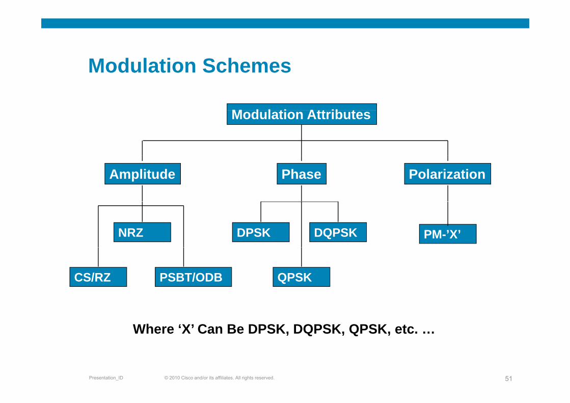
Modulation SchemesModulation Schemes
M d l ti Att ib tModulation Attributes
Amplitude Phase Polarization
NRZ DPSK DQPSK PM-’X’
CS/RZ PSBT/ODB QPSK
Where ‘X’ Can Be DPSK, DQPSK, QPSK, etc. …
© 2010 Cisco and/or its affiliates. All rights reserved.Presentation_ID 51
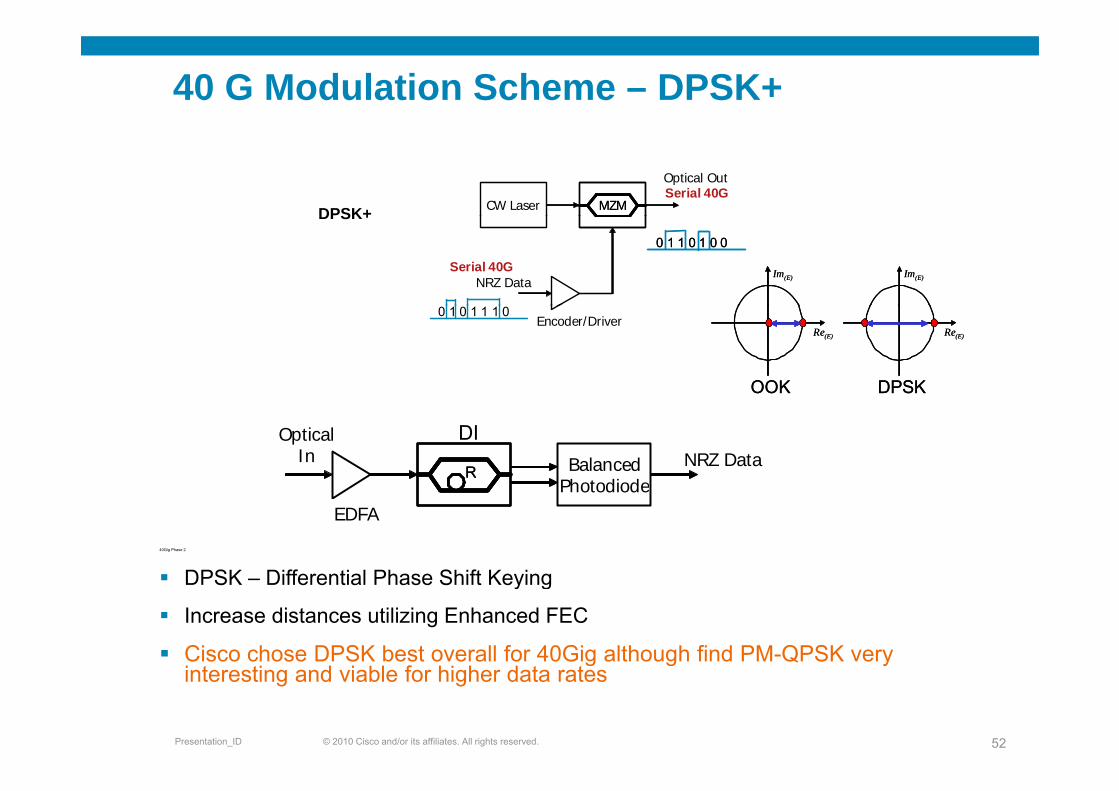
40 G Modulation Scheme – DPSK+
CW Laser MZMMZMSerial 40GOptical Out
DPSK+
NRZ Data
0 1 1 0 1 0 00 1 1 0 1 0 0
Serial 40G Im(E) Im(E)Im(E) Im(E)
DPSK+
Encoder/Driver0 1 0 1 1 1 0
Re(E)
OOK
Re(E)
DPSK
Re(E)
OOK
Re(E)
DPSK
BalancedPhotodiode
NRZ DataDI
RR
OpticalIn
40Gig Phase 2
DPSK Differential Phase Shift Keying
PhotodiodeEDFA
DPSK – Differential Phase Shift Keying
Increase distances utilizing Enhanced FEC
Cisco chose DPSK best overall for 40Gig although find PM-QPSK very
© 2010 Cisco and/or its affiliates. All rights reserved.Presentation_ID 52
g g yinteresting and viable for higher data rates
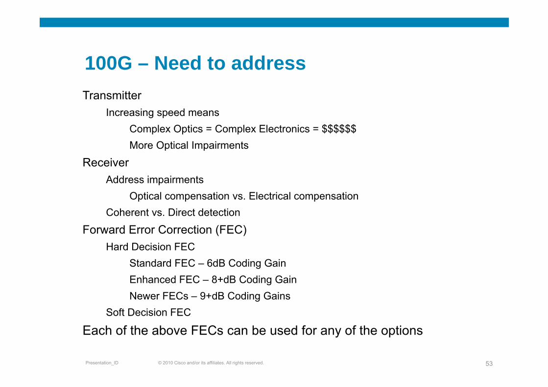
100G Need to address100G – Need to addressTransmitter
Increasing speed meansComplex Optics = Complex Electronics = $$$$$$More Optical Impairmentsp p
ReceiverAddress impairments
O ti l ti El t i l tiOptical compensation vs. Electrical compensationCoherent vs. Direct detection
Forward Error Correction (FEC)Hard Decision FEC
Standard FEC – 6dB Coding GainEnhanced FEC – 8+dB Coding GainEnhanced FEC 8+dB Coding GainNewer FECs – 9+dB Coding Gains
Soft Decision FEC
f C f f
© 2010 Cisco and/or its affiliates. All rights reserved.Presentation_ID 53
Each of the above FECs can be used for any of the options
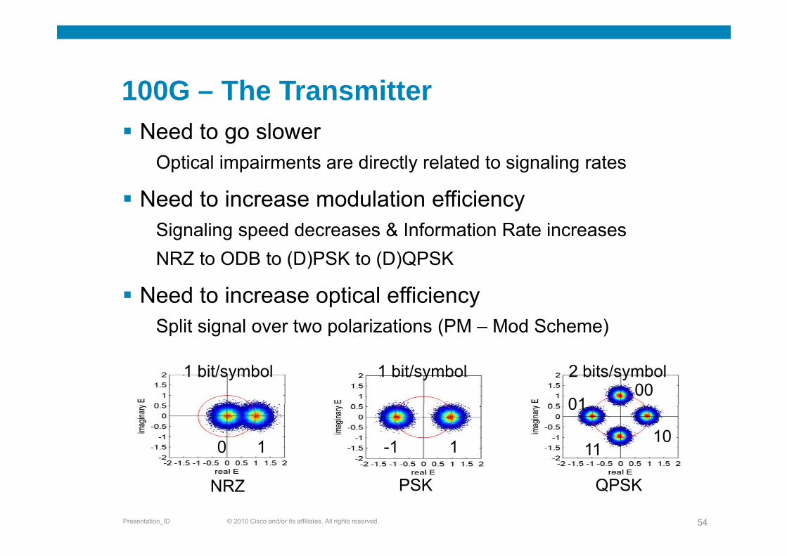
100G The Transmitter100G – The TransmitterNeed to go slower
Optical impairments are directly related to signaling rates
Need to increase modulation efficiencySignaling speed decreases & Information Rate increasesNRZ to ODB to (D)PSK to (D)QPSK
Need to increase optical efficiencySplit signal over two polarizations (PM – Mod Scheme)
1 bit/symbol 1 bit/symbol 2 bits/symbol00
01
0 1 1-1 1011
01
© 2010 Cisco and/or its affiliates. All rights reserved.Presentation_ID 54
NRZ PSK QPSK
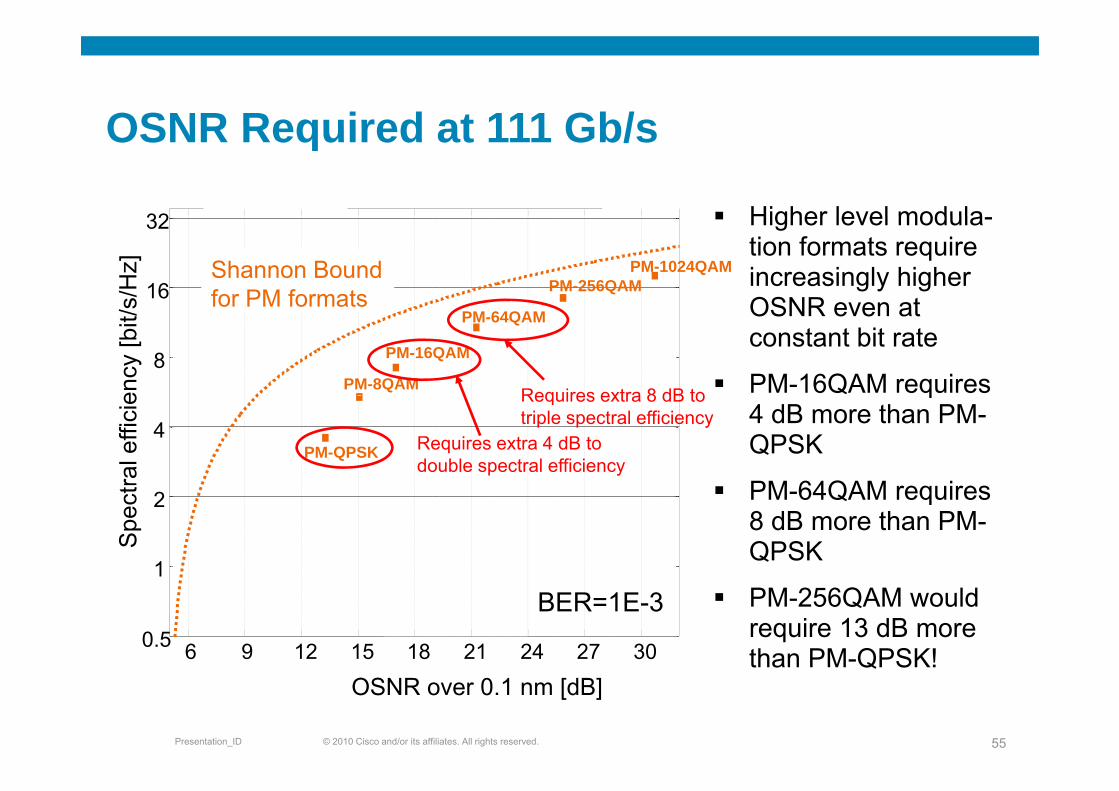
OSNR Required at 111 Gb/s
32
OSNR Required at 111 Gb/s
Higher level modula
16
32
s/H
z]
PM-256QAMPM-1024QAMShannon Bound
for PM formats
Higher level modula-tion formats require increasingly higher OSNR even at
8
ency
[bit/
s
PM-8QAM
PM-16QAM
PM-64QAMfor PM formats
Requires extra 8 dB to
OSNR even at constant bit rate
PM-16QAM requires
4
ral e
ffici
e
PM-QPSK Requires extra 4 dB to double spectral efficiency
Requires extra 8 dB to triple spectral efficiency
q4 dB more than PM-QPSK
PM 64QAM i
1
2
Spe
ct PM-64QAM requires 8 dB more than PM-QPSK
6 9 12 15 18 21 24 27 300.5
1PM-256QAM would require 13 dB more than PM-QPSK!
BER=1E-3
© 2010 Cisco and/or its affiliates. All rights reserved.Presentation_ID 55
OSNR over 0.1 nm [dB]than PM QPSK!
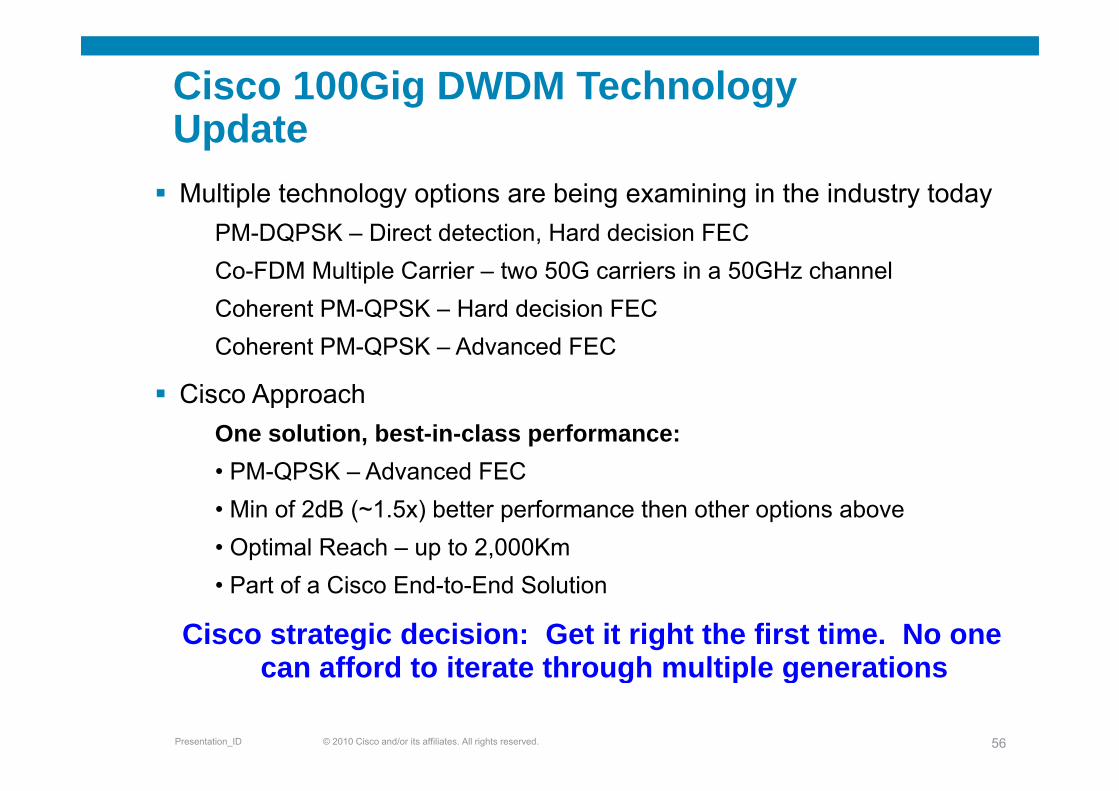
Cisco 100Gig DWDM Technology UpdateUpdateMultiple technology options are being examining in the industry today
PM-DQPSK – Direct detection, Hard decision FECCo-FDM Multiple Carrier – two 50G carriers in a 50GHz channelCoherent PM QPSK Hard decision FECCoherent PM-QPSK – Hard decision FECCoherent PM-QPSK – Advanced FEC
Cisco ApproachCisco ApproachOne solution, best-in-class performance:• PM-QPSK – Advanced FEC• Min of 2dB (~1.5x) better performance then other options above • Optimal Reach – up to 2,000Km• Part of a Cisco End-to-End Solution
Cisco strategic decision: Get it right the first time. No one can afford to iterate through multiple generations
© 2010 Cisco and/or its affiliates. All rights reserved.Presentation_ID 56
can afford to iterate through multiple generations
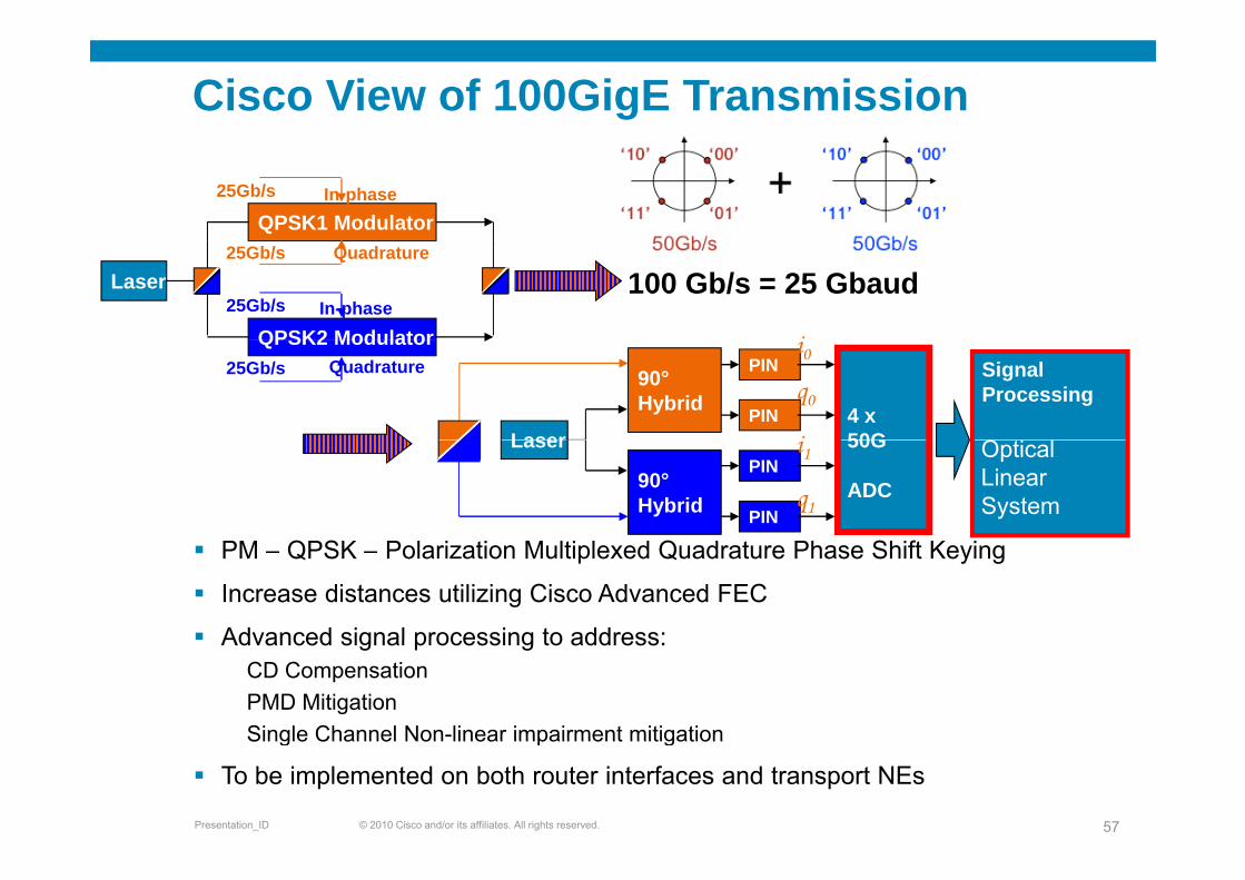
Cisco View of 100GigE Transmission
25Gb/s
QPSK1 ModulatorIn-phase
i
Laser25Gb/s
100 Gb/s = 25 Gbaud25Gb/s
QPSK2 Modulator
Quadrature
In-phase
4 x50G
SignalProcessing
PIN
PINLaser
90°Hybrid
i0q0
i O i l
QPSK2 Modulator25Gb/s Quadrature
50G
ADCPIN
PIN
Laser
90°Hybrid
i1
q1
Optical Linear System
PM – QPSK – Polarization Multiplexed Quadrature Phase Shift Keying
Increase distances utilizing Cisco Advanced FEC
Advanced signal processing to address:Advanced signal processing to address:CD CompensationPMD MitigationSingle Channel Non-linear impairment mitigation
© 2010 Cisco and/or its affiliates. All rights reserved.Presentation_ID 57
Single Channel Non linear impairment mitigation
To be implemented on both router interfaces and transport NEs
40G/100G Deployment Considerations in10G Optical Networks
Operating on 3rd party DWDM SystemOperating on 3rd party DWDM System
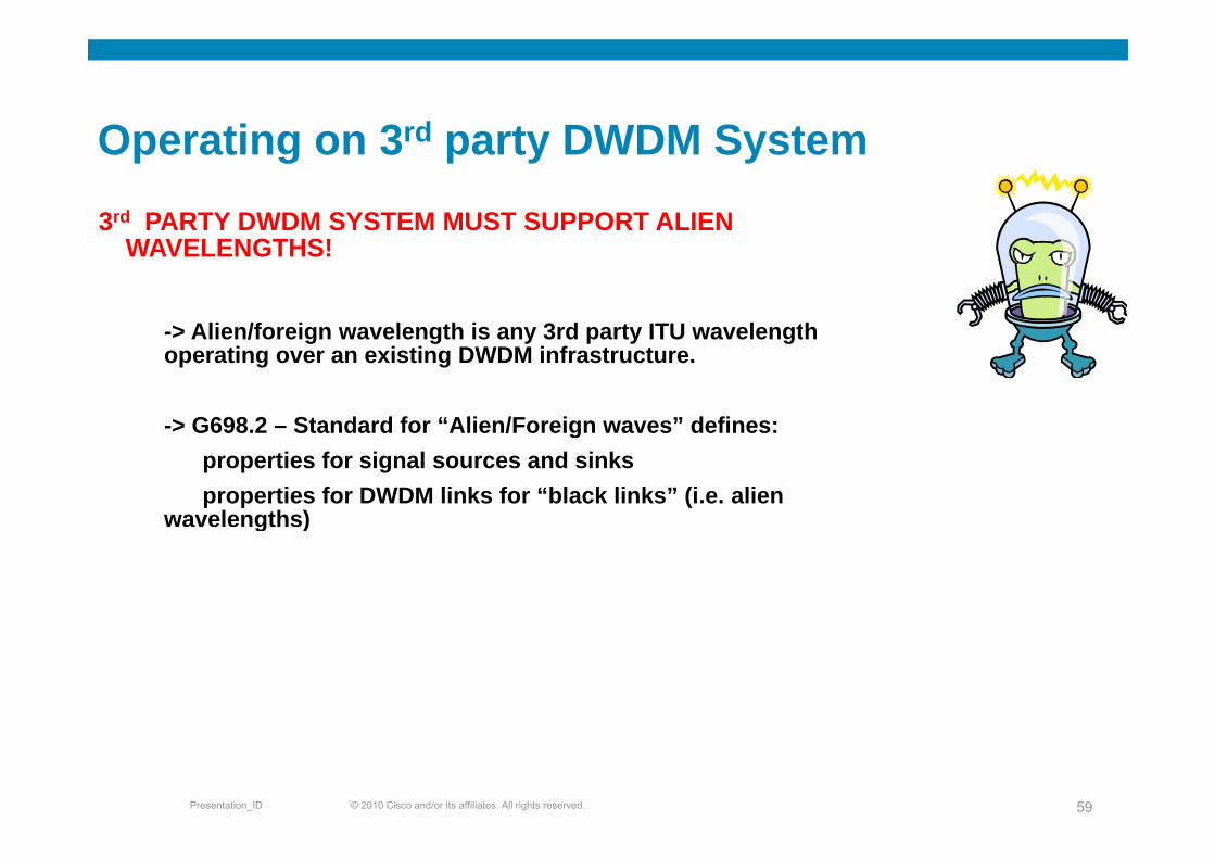
3rd PARTY DWDM SYSTEM MUST SUPPORT ALIEN WAVELENGTHS!
-> Alien/foreign wavelength is any 3rd party ITU wavelength-> Alien/foreign wavelength is any 3rd party ITU wavelength operating over an existing DWDM infrastructure.
-> G698 2 – Standard for “Alien/Foreign waves” defines:> G698.2 Standard for Alien/Foreign waves defines:properties for signal sources and sinksproperties for DWDM links for “black links” (i.e. alien
wavelengths)g )
© 2010 Cisco and/or its affiliates. All rights reserved.Presentation_ID 59
Network ArchitectureD i C id tiDesign Considerations
40G i diff f 10G
Noise and Impairment Limits
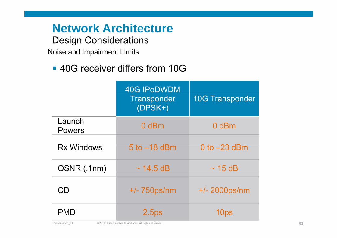
40G receiver differs from 10G
40G IPoDWDM40G IPoDWDMTransponder
(DPSK+)10G Transponder
L hLaunch Powers 0 dBm 0 dBm
Rx Windows 5 to 18 dBm 0 to 23 dBmRx Windows 5 to –18 dBm 0 to –23 dBm
OSNR (.1nm) ~ 14.5 dB ~ 15 dB
CD +/- 750ps/nm +/- 2000ps/nm
© 2010 Cisco and/or its affiliates. All rights reserved.Presentation_ID 60
PMD 2.5ps 10ps
What to take into consideration ?Basics that you should start withBasics that you should start with
Fib T•Fiber Type
•OSNR
•Chromatic Dispersion
•Polarization Mode Dispersion
Spectrum Allocation•Spectrum Allocation
•Channel Spacingp g
•Design Margin
© 2010 Cisco and/or its affiliates. All rights reserved.Presentation_ID 61
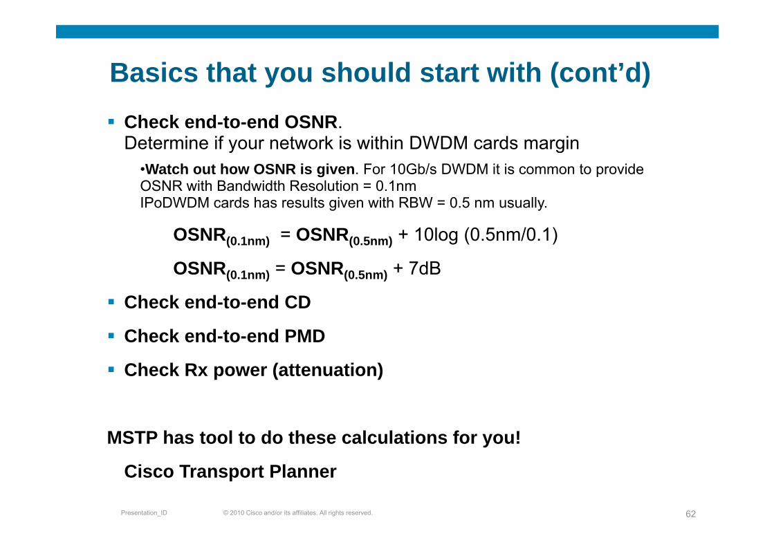
Basics that you should start with (cont’d)y ( )Check end-to-end OSNR.Determine if your network is within DWDM cards marginy g
•Watch out how OSNR is given. For 10Gb/s DWDM it is common to provide OSNR with Bandwidth Resolution = 0.1nmIPoDWDM cards has results given with RBW = 0.5 nm usually.
OSNR(0.1nm) = OSNR(0.5nm) + 10log (0.5nm/0.1)
OSNR(0 1nm) = OSNR(0 5nm) + 7dBOSNR(0.1nm) OSNR(0.5nm) 7dB
Check end-to-end CD
Check end to end PMDCheck end-to-end PMD
Check Rx power (attenuation)
MSTP has tool to do these calculations for you!
© 2010 Cisco and/or its affiliates. All rights reserved.Presentation_ID 62
Cisco Transport Planner
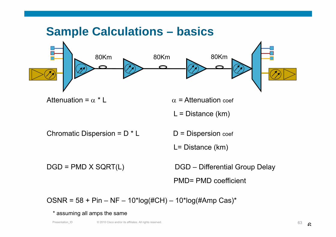
Sample Calculations – basics
80Km 80Km 80Km
Attenuation = α * L α = Attenuation coef
L = Distance (km)
Chromatic Dispersion = D * L D = Dispersion coef
L Di t (k )L= Distance (km)
DGD = PMD X SQRT(L) DGD – Differential Group Delay
PMD= PMD coefficient
OSNR = 58 + Pin NF 10*log(#CH) 10*log(#Amp Cas)*
© 2010 Cisco and/or its affiliates. All rights reserved.Presentation_ID 63 6
OSNR = 58 + Pin – NF – 10*log(#CH) – 10*log(#Amp Cas)*
* assuming all amps the same

100G: Where are we today?100G: Where are we today?
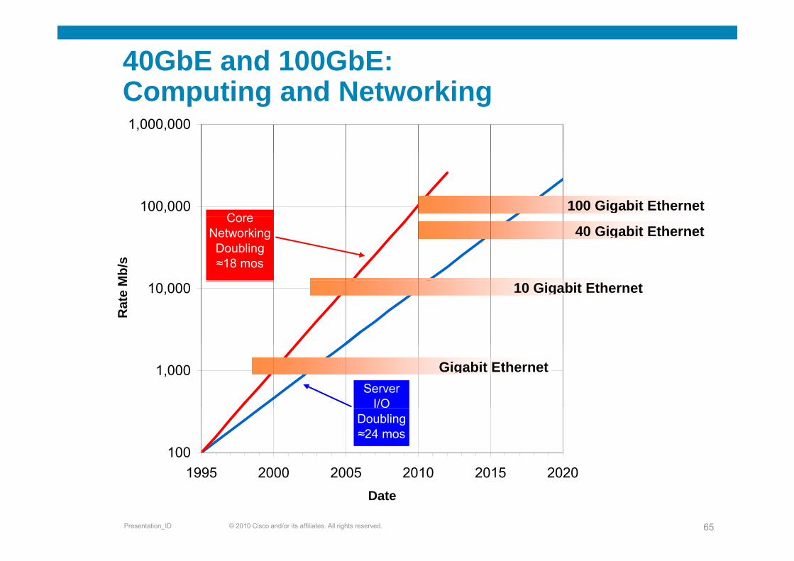
40GbE and 100GbE: Computing and NetworkingComputing and Networking1,000,000
100,000Core
100 Gigabit Ethernet
Mb/
s
CoreNetworkingDoubling≈18 mos
40 Gigabit Ethernet
10,000
Rat
e M 10 Gigabit Ethernet
1,000Server
I/O
Gigabit Ethernet
1001995 2000 2005 2010 2015 2020
Doubling≈24 mos
© 2010 Cisco and/or its affiliates. All rights reserved.Presentation_ID 65
1995 2000 2005 2010 2015 2020Date
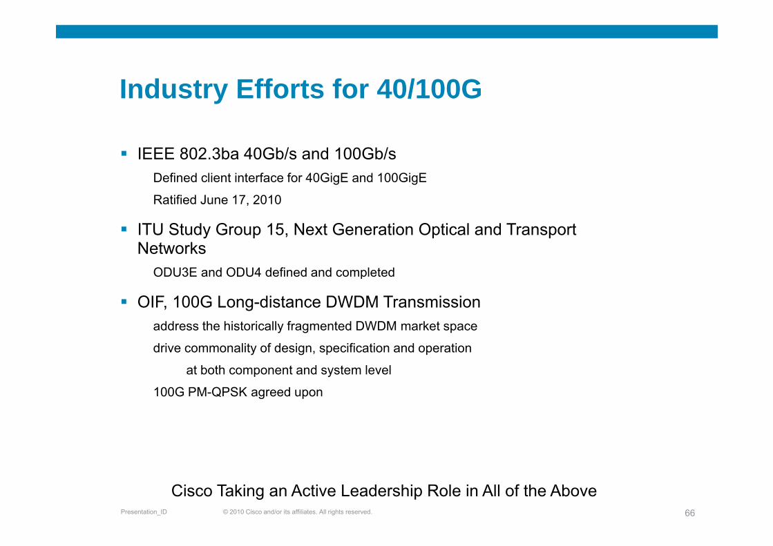
Industry Efforts for 40/100GIndustry Efforts for 40/100G
IEEE 802 3b 40Gb/ d 100Gb/IEEE 802.3ba 40Gb/s and 100Gb/sDefined client interface for 40GigE and 100GigE
Ratified June 17, 2010
ITU Study Group 15, Next Generation Optical and Transport Networks
ODU3E and ODU4 defined and completedODU3E and ODU4 defined and completed
OIF, 100G Long-distance DWDM Transmissionaddress the historically fragmented DWDM market space
drive commonality of design, specification and operation
at both component and system level
100G PM-QPSK agreed upong p
© 2010 Cisco and/or its affiliates. All rights reserved.Presentation_ID 66
Cisco Taking an Active Leadership Role in All of the Above
Key TakeawaysKey Takeaways
100GE d 40GE h b tifi d J 17 2010100GE and 40GE have been ratified June 17, 2010
100GE demand is high from SP customers to address networking and aggregation issuesnetworking and aggregation issues
Cisco is taking a strong leadership role:Both LAN and WAN technologiesBoth LAN and WAN technologiesIndustry standards Components and sub-components and obviously in 100G IP forwarding!
Cisco launched the industry’s first 100GE interface!!June 2008 – client sideMarch 2010 100GigE on CRS 3 live AT&TMarch 2010 – 100GigE on CRS-3 – live AT&T
© 2010 Cisco and/or its affiliates. All rights reserved.Presentation_ID 67
What Comes After 100Gig?What Comes After 100Gig?
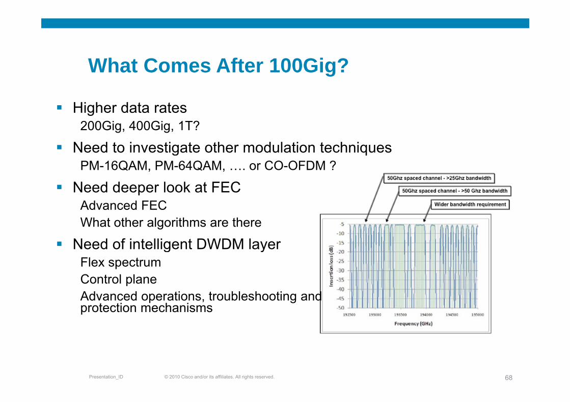
Higher data ratesHigher data rates200Gig, 400Gig, 1T?
Need to investigate other modulation techniquesg qPM-16QAM, PM-64QAM, …. or CO-OFDM ?
Need deeper look at FECAd d FECAdvanced FECWhat other algorithms are there
Need of intelligent DWDM layerNeed of intelligent DWDM layerFlex spectrumControl planeAd d ti t bl h ti dAdvanced operations, troubleshooting and protection mechanisms
© 2010 Cisco and/or its affiliates. All rights reserved.Presentation_ID 68

SummarySummary
Cisco IPoDWDM Summary and BenefitsCisco IPoDWDM Summary and Benefits
IP traffic continues to growIP traffic continues to grow24 Exabytes per month by 2012Driven by application service convergence on IP
Optical layer must be openOptical layer must be openOptical layer needs to be in place for 5–10 year minimumCannot afford to tie transmission rate innovation to DWDM vendor’s roadmapEncourages innovation by maintaining competition
New services converging on IP need more robustnessIPoDWDM delivers robustness, reliability and cost savings
Fewer shelves—less CO space, less power, less gear improving reliabilityF O t l t i t i d li bilitFewer Opto electronic components—increased reliability Half number of patch cable—dirty connectors and miss connection account for majority of problems in fieldG.709 PMs to the interface not masked by transponder—improved network resiliencyE bl d d f tEnable advanced features40G over current 10G optical network
Investigation underway in 1 Tbps
© 2010 Cisco and/or its affiliates. All rights reserved.Presentation_ID 70
AcronymsAcronymsBER – Bit Error Rate
CD – Chromatic Dispersion
MMF – Multi Mode Fiber
OIF – Optical Internetworking Forum
CTC – Cisco Transport Planner
DGD – Differential Group Delay
DWDM D W Di i i M lti l i
OSNR – Optical Signal to Noise Ratio
PM – Performance Monitoring
PMD – Polarization Mode DispersionDWDM – Dense Wave Division Multiplexing
FEC- Forward Error Correction
FRR – Fast Re-Route
PMO – Present Mode of Operations
QAM – Quadrature Amplitude Modulation
ROADM Reprogrammable Optical Add/DropFPM – Four Photon Mixing
FWM – Four Wave Mixing
GMPLS – General Multiprotocol Label Switching
ROADM – Reprogrammable Optical Add/Drop Multiplexer
SLA – Service Level Agreement
SMF – Single Mode FiberGMPLS – General Multiprotocol Label Switching
IEEE – Institute of Electrical and Electronics Engineers
ITU – International Telecommunication Union
SR- Short Reach
SRLG – Shared Risk Link Groups
VOD Video on DemandITU International Telecommunication Union
LMP – Link Management Protocol
MAC- Media Access Control
VOD – Video on Demand
VTXP – Virtual Transponder
XPM – Cross Phase Modulation
© 2010 Cisco and/or its affiliates. All rights reserved.Presentation_ID 71

Q&AQ&A
© 2010 Cisco and/or its affiliates. All rights reserved.Presentation_ID 73