IPA-48S - Alvaco
54
IPA-48S User Manual Version 1.0 RECYCLABLE
Transcript of IPA-48S - Alvaco

IPA-48SUser Manual
Version 1.0
RECYCLABLE

Contents:
WARNING INSTRUCTIONS................................................................................................................3
1.1IPA-48S Overview............................................................................................................................................ 4
1.2Application....................................................................................................................................................... 4
1.3Specification ................................................................................................................................................... 5
2.1Description of Hardware................................................................................................................................. 7
2.2Accessory Parts check................................................................................................................................... 9
............................................................................................................................................................................. 10
3.2Configuration................................................................................................................................................. 17
3.2.2 Bridge Features.......................................................................................................................17
............................................................................................................................................................................. 17
3.2.2.1 ............................................................................................................................................... 17
Bridge Configuration.......................................................................................................................17
............................................................................................................................................................................. 18
............................................................................................................................................................................. 27
............................................................................................................................................................................. 28
............................................................................................................................................................................. 28
3.2.5.1 Ingress..................................................................................................................................30
3.2.5.1.1 Setup:.................................................................................................................................30
............................................................................................................................................................................. 30
............................................................................................................................................................................. 31
3.2.5.1.2 Attachment.........................................................................................................................31
3.2.5.2 Egress...............................................................................................................................31
............................................................................................................................................................................. 33
3.3.1.2 Protocal Attachment...........................................................................................................35
............................................................................................................................................................................. 391

............................................................................................................................................................................. 53
2

WARNING INSTRUCTIONSWARNING INSTRUCTIONS
Before installing IPA-48S, the following the safety instructions must be complied.
1. All installation, repair or replacement procedures must be performed by qualified service
personnel.
2. Before attempting to operate or repair this product, make sure the IPA-48S is
properly grounded.
3. The maximum recommended operating temperature for the IPA-48S is 65ºC.
Care must be taken to allow sufficient air circulation.
4. The connections and equipment that supply power to the IPA-48S should be
capable of operating safely within the maximum power requirements of the IPA-48S.
If the input DC voltage is more than 10% lower than the standard the IPA-48S may
malfunction. Make sure that the power supply is stable and the voltage is correct.
5. Do not allow anything to rest on the power cord, and do not locate the product where the
power cord can be stepped on. Do not touch exposed connections, components or wiring
when power is present.
6. To reduce the risk of fire or any other malfunction and damages to the IPA-48S, use the
cables and power adapter provided in the package.
7. Following installation and the final configuration, the product must comply with the applicable
safety standards and regulatory requirements of the country in which it is installed. If
necessary, request technical support.
8. Do not operate this product with panels removed or with suspected failure or damage to
electrical components.
9. IPA-48S is not water-proofed. Never place or install the product in a wet location unless
specially designed waterproof protection is present.
iTAS will not be responsible for any damages or injuries to the IPA-48S, environment, or
operating personnel if any of the safety instructions described above are violated or operating the
device in the non-recommended conditions.
3
1 Introduction
Thank you for choosing the IPA-48S as your broadband access solution. This manual will help
you with the setup and configuration of your product.
1.1 IPA-48S Overview
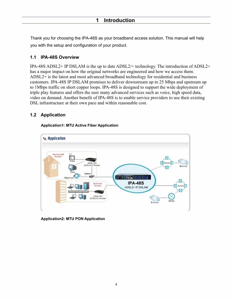
IPA-48S ADSL2+ IP DSLAM is the up to date ADSL2/+ technology. The introduction of ADSL2+ has a major impact on how the original networks are engineered and how we access them. ADSL2+ is the latest and most advanced broadband technology for residential and business customers. IPA-48S IP DSLAM promises to deliver downstream up to 25 Mbps and upstream up to 1Mbps traffic on short copper loops. IPA-48S is designed to support the wide deployment of triple play features and offers the user many advanced services such as voice, high speed data, video on demand. Another benefit of IPA-48S is to enable service providers to use their existing DSL infrastructure at their own pace and within reasonable cost.
1.2 Application
Application1: MTU Active Fiber Application
Application2: MTU PON Application
4

1.3 Specification
System Features Protocol Support
λ DSL/POTS Ports
λ 48-port ADSL/2/2+ subscriber interface with built-in POTS Splitter
λ Centronic 50-pin connector for Telco line in and out
λ Alarm Relay for 3 inputs and 1 output
λ Two Uplink Port SFP/GE Combos
λ Plugable FAN Module
λ ATM Functionality
λ RFC 1483/2684 multi-protocol encapsulation over ATM AAL5
λ LLC/VCMUX auto detection
λ VBR/GFR/UBR/ABR/CBR/VBR-nrt Policing
λ VBR/GFR/UBR+/WFQ/UBR/GFR/VBR-nrt Shaping
λ Bridging Port
λ Tagged/Untagged/All Frame Filter
λ VLAN Ingress Filter
λ Static and Port-based VLAN
λ S-tag/C-tag Priority Mapping
λ Support for Transparent LAN Service (TLS)
λ VLAN
λ Single or Double tag support
λ N:1/1:1 VLAN
λ Forwarding Database
λ 16K MAC address entries
λ Dynamic/Static FDB
λ Forwarding N:1/1:1 VLAN
λ Multicast
λ IGMPv1, v2, v3 snooping and proxy
λ PPPoE Intermediate Agent
λ DHCP L2 Relay – TR101 Appendix B
λ IEEE 802.1x
λ STP (802.1D) / RSTP (802.1W)λ SNTP Clientλ SysLog Client
λ ADSL/ADSL2/ADSL2+ Interfaceλ ADSL/ADSL2/ADSL2+: Downstream DMT data rate
of 32 kb/s up to 25 Mbps; Upstream DMT data rate of 32 kb/s up to 1 Mbps
λ Complies with the ITU G.992.1 (G.DMT), G.DMT.bis, ITU G.992.2 (G.Lite), ANSI T1.413 issue 2, ITU G.994.1 (G.handshake) for ADSL, G.992.3 for ADSL2, and G.992.5 for ADSL2+ standards
λ Extended power management capabilities to optimize power consumption for each application
λ Distance up to 18 kft
λ Management
λ Local RS-232 CLI and Ethernet Web/SNMP/TELNET management
λ Remote in-band Web/SNMP/TELNET managementλ Firmware upgradeable via HTTP, FTP or TFTPλ Support for SNMP v1, v2, v3
λ Operating Requirements
λ Operating Temperature: -20 to 65°Cλ Storage Temperature: -30 to 70°Cλ Operating Humidity: 5 to 90% RH non-condensing
λ Dimensions and Weight
λ Dimensions: 260 mm (d) x 440 mm (w) x 44mm (h) λ Weight: 6kg
λ Power
λ AC power model: 90 VAC ~ 240 VAC, 50-60 Hzλ DC power model: -36 VDC ~ -72 VDCλ Power Consumption: 70 Watts
λ Certifications
5

λ Up to 256 multicast addresses
λ IGMP v1, v2, v3
λ Multicast VLAN mapping
o Independent VLAN multicast (IVM).
o Shared VLAN Multicast (SVM)
λ Policer
λ Broadcast/Unknown rate limit
λ 802.1P Priority rate limit
λ Access Control List
λ Filter on MAC, IP, Ether Type and port
λ Packet size 64 byte to 1522 byte
λ EMCλ FCC Part 15 Class Aλ CE-EMC Class A
λ Safetyλ EN60950-1λ ITU-T K.20
6

2 Hardware Setup and Startup
2.1 Description of Hardware
2.1.1. Power Outlet
AC: 90 ~ 240VAC, 50/60Hz; 70Watts (Max.)
DC: -36 ~ -72 VDC; 70Watts (Max.)
2.1.2. Optical Ethernet Port (UP1 and UP2) – SFP Cage
- Two 1000BASE-X (SX, LX, LHX, ZX ) ports- Two uplink ports or- One port is for uplink and another one for downlink (stacking port)
2.1.3. Electrical Ethernet Port (UP1 and UP2) – RJ45
- Two automatic MDI/MDI-X 1000/100/10 BASE T Ports- Two uplink ports or- One port is for uplink and another one for downlink (stacking port)
2.1.4. System LED
-7
Pin Signal Name1 Transmit Data plus (TD1+)2 Receive Data minus (RD1-)3 Transmit Data plus (TD2+)4 Transmit Data plus (TD3+)5 Receive Data minus (RD3-)6 Receive Data minus (RD2-)7 Transmit Data plus (TD4+)8 Receive Data minus (RD4-)
System Status LEDsLED Condition StatusPWR On Green Power is properly suppliedSYS On Green System initialization is properly completedALM On Red System alarm is activeTST On Amber System test in progress

2.1.5. LINE ports and PSTN ports
Line Port Pin Assignment
PIN # Usage PIN# Usage1 DSL/PSTN 1-T 26 DSL/PSTN 1-R
2 DSL/PSTN 2-T 27 DSL/PSTN 2-R
3 DSL/PSTN 3-T 28 DSL/PSTN 3-R
4 DSL/PSTN 4-T 29 DSL/PSTN 4-R
5 DSL/PSTN 5-T 30 DSL/PSTN 5-R
6 DSL/PSTN 6-T 31 DSL/PSTN 6-R
7 DSL/PSTN 7-T 32 DSL/PSTN 7-R
8 DSL/PSTN 8-T 33 DSL/PSTN 8-R
9 DSL/PSTN 9-T 34 DSL/PSTN 9-R
10 DSL/PSTN 10-T 35 DSL/PSTN 10-R
11 DSL/PSTN 11-T 36 DSL/PSTN 11-R
12 DSL/PSTN 12-T 37 DSL/PSTN 12-R
13 DSL/PSTN 13-T 38 DSL/PSTN 13-R
14 DSL/PSTN 14-T 39 DSL/PSTN 14-R
15 DSL/PSTN 15-T 40 DSL/PSTN 15-R
16 DSL/PSTN 16-T 41 DSL/PSTN 16-R
17 DSL/PSTN 17-T 42 DSL/PSTN 17-R
18 DSL/PSTN 18-T 43 DSL/PSTN 18-R
19 DSL/PSTN 19-T 44 DSL/PSTN 19-R
20 DSL/PSTN 20-T 45 DSL/PSTN 20-R
21 DSL/PSTN 21-T 46 DSL/PSTN 21-R
22 DSL/PSTN 22-T 47 DSL/PSTN 22-R
23 DSL/PSTN 23-T 48 DSL/PSTN 23-R
24 DSL/PSTN 24-T 49 DSL/PSTN 24-R
25 NOT USED 50 NOT USED
-8

2.2 Accessory Parts check
Check the following items in your package. Contact our sales representatives if any item is missing or damaged. IPA-48S x 1RJ-45 cable x 1RS232 cable x 1Power Cable x 1Mounting hardware pkg x 1
-9

3 EmWeb Setup and Startup
1. To access EmWeb on the IPA-48S, one has to connect uplink port and enter URL below at web browser.
Uplink #1 (UP1): http://192.168.100.111Uplink #2 (UP2): http://192.168.1.111
2. If you first time login the EmWeb, the default User name/Password as follows User Name: adminPassword: admin
3. Click on . You are now ready to configure IPA-48S IP DSLAM using EmWeb.
EmWeb provides a series of
web pages that you can use
to setup and configure the IPA-48S IP DSLAM. These pages are organized into four main
topics. You can select each of the following topics from the menu on the left-hand side of the
main window:
• System: The System section lets you carry out system commands like Firmware Update,
System Reboot, Save Config, and Recall Config.
• Configuration: information about the current configuration of various system features with
options to change the configuration.
• Advanced: information about the current configuration of various system features with options
to change the configuration.
• Status: Information about the current setup and status of the system.
• Maintenance: show the statistics of the interface.
The changes made via web pages will immediately reflect in all elements of the network.
The exact information displayed on each web page depends on the specific configuration that you are using. The following sections give you a general overview of the setup and configuration details.
-10
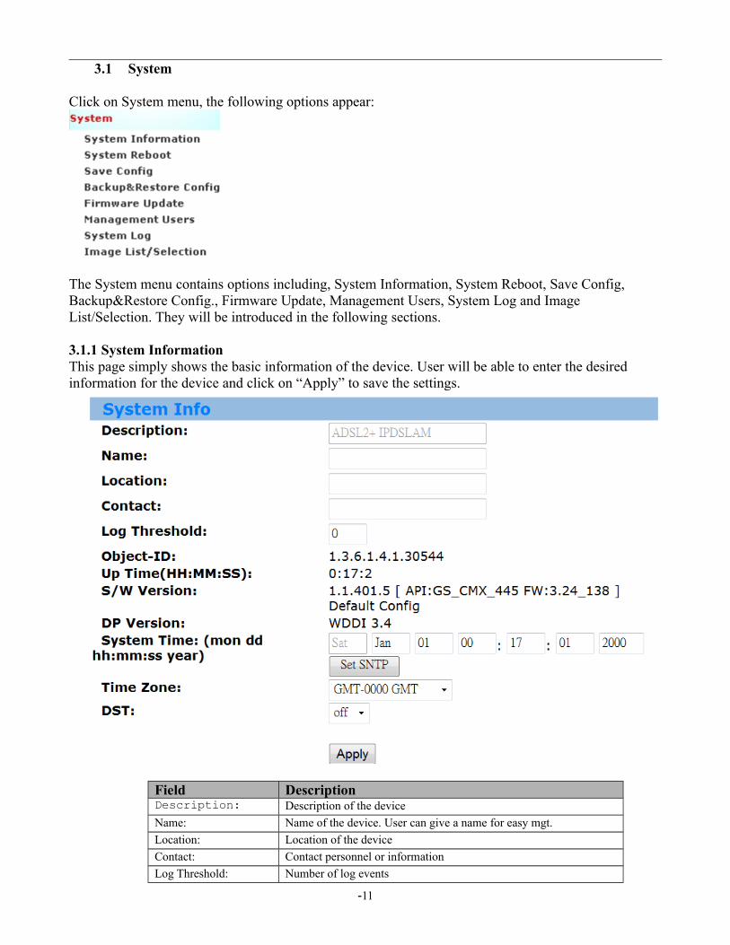
3.1 System
Click on System menu, the following options appear:
The System menu contains options including, System Information, System Reboot, Save Config, Backup&Restore Config., Firmware Update, Management Users, System Log and Image List/Selection. They will be introduced in the following sections.
3.1.1 System InformationThis page simply shows the basic information of the device. User will be able to enter the desired information for the device and click on “Apply” to save the settings.
Field DescriptionDescription: Description of the device
Name: Name of the device. User can give a name for easy mgt.
Location: Location of the device
Contact: Contact personnel or information
Log Threshold: Number of log events
-11
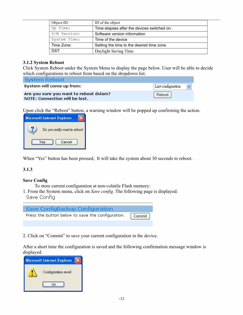
Object-ID: ID of the objectUp Time: Time elapses after the devices switched on.S/W Version: Software version informationSystem Time: Time of the device
Time Zone: Setting the time to the desired time zone
DST: Daylight Saving Time
3.1.2 System RebootClick System Reboot under the System Menu to display the page below. User will be able to decide which configurations to reboot from based on the dropdown list.
Upon click the “Reboot” button, a warning window will be popped up confirming the action.
When “Yes” button has been pressed, It will take the system about 30 seconds to reboot.
3.1.3
Save Config To store current configuration at non-volatile Flash memory:
1. From the System menu, click on Save config. The following page is displayed:
2. Click on “Commit” to save your current configuration in the device.
After a short time the configuration is saved and the following confirmation message window is displayed.
-12
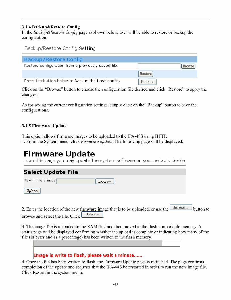
3.1.4 Backup&Restore ConfigIn the Backup&Restore Config page as shown below, user will be able to restore or backup the configuration.
Click on the “Browse” button to choose the configuration file desired and click “Restore” to apply the changes.
As for saving the current configuration settings, simply click on the “Backup” button to save the configurations.
3.1.5 Firmware Update
This option allows firmware images to be uploaded to the IPA-48S using HTTP. 1. From the System menu, click Firmware update. The following page will be displayed:
2. Enter the location of the new firmware image that is to be uploaded, or use the button to
browse and select the file. Click .
3. The image file is uploaded to the RAM first and then moved to the flash non-volatile memory. A status page will be displayed confirming whether the upload is complete or indicating how many of the file (in bytes and as a percentage) has been written to the flash memory.
4. Once the file has been written to flash, the Firmware Update page is refreshed. The page confirms completion of the update and requests that the IPA-48S be restarted in order to run the new image file. Click Restart in the system menu.
-13
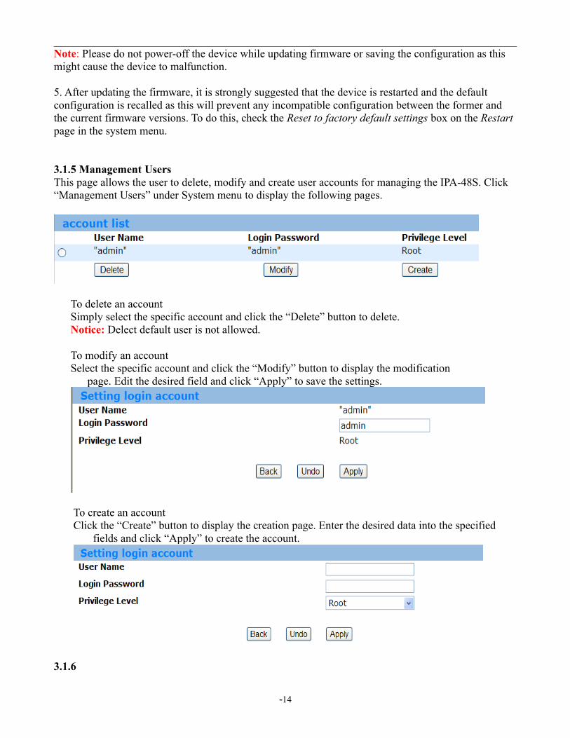
Note: Please do not power-off the device while updating firmware or saving the configuration as this might cause the device to malfunction.
5. After updating the firmware, it is strongly suggested that the device is restarted and the default configuration is recalled as this will prevent any incompatible configuration between the former and the current firmware versions. To do this, check the Reset to factory default settings box on the Restart page in the system menu.
3.1.5 Management UsersThis page allows the user to delete, modify and create user accounts for managing the IPA-48S. Click “Management Users” under System menu to display the following pages.
To delete an account Simply select the specific account and click the “Delete” button to delete. Notice: Delect default user is not allowed.
To modify an account Select the specific account and click the “Modify” button to display the modification
page. Edit the desired field and click “Apply” to save the settings.
To create an account Click the “Create” button to display the creation page. Enter the desired data into the specified
fields and click “Apply” to create the account.
3.1.6
-14

System Log 1. System Log ConfigThis page allows the user to create or delete syslog send server. Click “Syslog Sender Config” under System Log of the System menu to display the following image.
Use the dropdown box next to enable or disable the sender. Note: In order to make Syslog Sender Enable to be effective, user need to set the Log Threshold under the System Info to be a non-zero value.
User can also create or delete the Collector List by clicking the “Delete” or “Create” buttons to display the following image.
2. Syslog Log This page lists the entire system event log. User will be able to check the event history under this section. User can click “Reload” to refresh the page for updated events or click “Reset” to clear the past events. To display the following page, simply click Syslog Log of the System Log under the System menu.
3.1.7 Image List/SelectionThis page allows the user to display repository image version and to change repository. User can simply to check Select option next to the desired image version and click “Apply” to change the image version. Click on the Image List under System menu to display the following page.
-15

-16
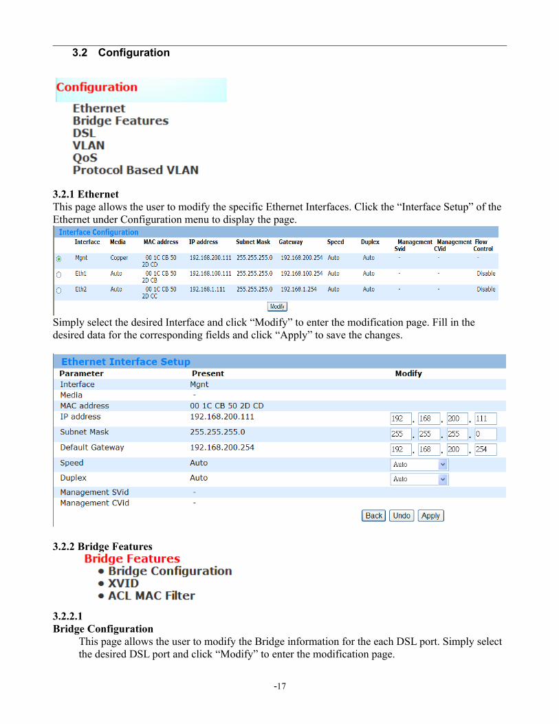
3.2 Configuration
3.2.1 EthernetThis page allows the user to modify the specific Ethernet Interfaces. Click the “Interface Setup” of the Ethernet under Configuration menu to display the page.
Simply select the desired Interface and click “Modify” to enter the modification page. Fill in the desired data for the corresponding fields and click “Apply” to save the changes.
3.2.2 Bridge Features
3.2.2.1 Bridge Configuration
This page allows the user to modify the Bridge information for the each DSL port. Simply select the desired DSL port and click “Modify” to enter the modification page.
-17

Once the modification page displayed, enter the desired information to the corresponding fields and click “Modify” to save the settings.
-18

Here need to add more information for above figure.Field Description
Port ID The bridge port ID. Valid values: 1...26 (1...24: DSL, 25...26: eth)
Admin Status Show the port disable and enable status
Port Type
Accept Frame type
All: forward tagged/untagged packet by defaultTagged: Forward Tagged packetUntagged: Forward Untagged packet
Default CVID Customer VLAN ID, which is used to be the default Customer VLAN ID. Valid values: 1...4093
Default SVID Service VLAN ID, which is used to be the default Service VLAN ID. Valid values: 1...4093
Default Priority
Set 802.1p value for the port, valid value: 0-7
Default Priority Mode
Untagged :mean no 802.1p priority tag trafficAll: forward any 802.1p priority tag traffic
Learning Mode The state of learning on this bridge port, which is used to learn VLAN ID. Valid values: disable / enable
3.2.2.2 XVID
This page displays the list of all CVIDs for any specific ports. You can transfer the CVID to predefined SVID/CVID. Click CVID under the Configuration menu and display the page below.
Click on “Modify” button to display the modification page as below, where user will be able to modify CVID member list translation rule of any specific ports. Simply use the dropdown list to choose the desired option and click “Apply” to save the settings.
3.2.2.3. ACL MAC FilterClick on flter Table config and add the VLAN ID and MAC filter mapping table at first.
-19
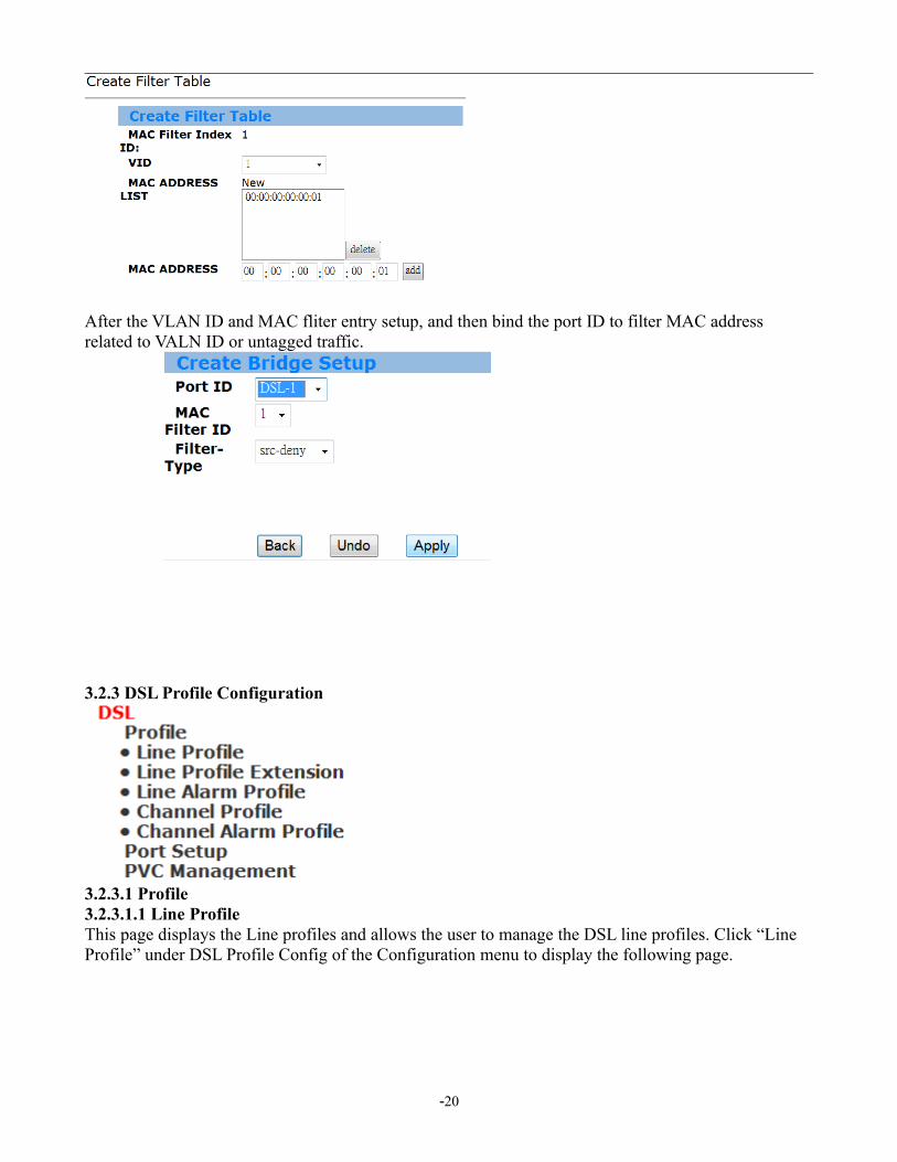
After the VLAN ID and MAC fliter entry setup, and then bind the port ID to filter MAC address related to VALN ID or untagged traffic.
3.2.3 DSL Profile Configuration
3.2.3.1 Profile 3.2.3.1.1 Line ProfileThis page displays the Line profiles and allows the user to manage the DSL line profiles. Click “Line Profile” under DSL Profile Config of the Configuration menu to display the following page.
-20
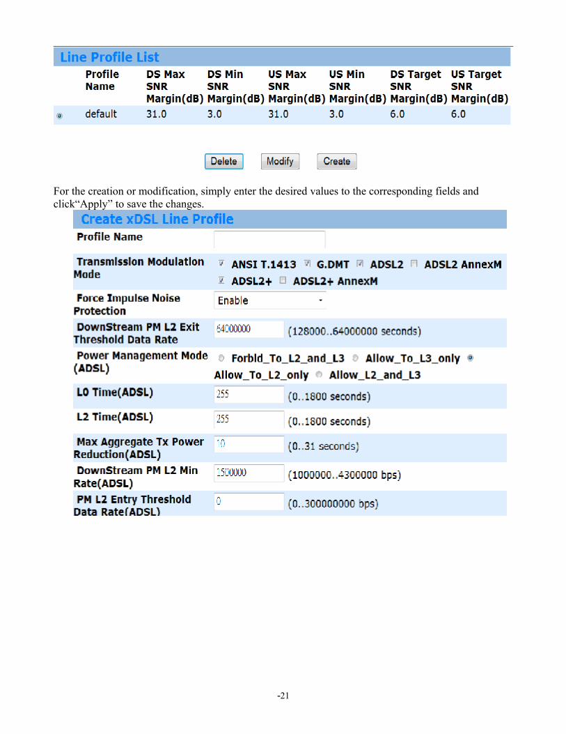
For the creation or modification, simply enter the desired values to the corresponding fields and click“Apply” to save the changes.
-21

3.2.3.1.2 Line Profile ExtensionThis page displays current line profile extension information. Click “Line Profile Extension” under DSL of the Configuration menu to display the following page for line profile extention management.
For the creation or modification, simply enter the desired values to the corresponding fields and click “Apply” to save the changes.
-22

3.2.3.1.3 Line Alarm Profile This page displays all profile information and allows the user to manage DSL line alarm profiles.
For the creation or modification, simply enter the desired values to the corresponding fields and click “Apply” to save the changes.
-23

3.2.3.1.4 Channel ProfileClick “Channel Profile” under DSL of the Configuration menu to display the following page and allow uer to manage them.
For the creation or modification, simply enter the desired values to the corresponding fields and click “Apply” to save the changes.
-24
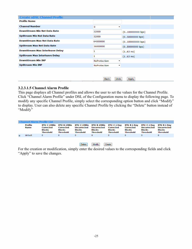
3.2.3.1.5 Channel Alarm Profile This page displays all Channel profiles and allows the user to set the values for the Channel Profile. Click “Channel Alarm Profile” under DSL of the Configuration menu to display the following page. To modify any specific Channel Profile, simply select the corresponding option button and click “Modify” to display. User can also delete any specific Channel Profile by clicking the “Delete” button instead of “Modify”
For the creation or modification, simply enter the desired values to the corresponding fields and click “Apply” to save the changes.
-25

3.2.3.2 Port Setup
3.2.3.2 Port Setup3.2.3.2.1 Line InterfaceThe Line interface page alow user to disable/enable each DSL port.
3.2.3.2.2 Line ProfileThis page allows the user to display the profile mapping information as well as letting the user to apply other line profile to specified DSL port. Click “Line Profile” under DSL Port Mapping of the Configuration menu to display the following page. To modify any specific Line Profile, simply select the corresponding option button and click “Apply” to change.
-26

3.2.3.2.3 Line Profile ExtensionThis page allows the user to display the profile mapping information as well as lettingthe user to apply other line profile extension to specified DSL port. Click “Line Profile Extension” under DSL of the Configuration menu to display the following page. To modify any specific Profile, simply select the corresponding option button and click “Apply” to change.
3.2.3.2.4 Line Alarm ProfileThis page allows the user to display the profile mapping information as well as letting the user to apply other alarm profile to specified DSL port. To modify any specific Line Alarm Profile, simply select the corresponding option button and click “Apply” to change.
3.2.3.2.5
-27

Channel ProfileThis page allows the user to display the profile mapping information as well as letting the user to apply other channel profile to specified DSL port. Click “Channel Profile” under DSL of the Configuration menu to display the following page. To modify any specific Channel Profile, simply select the corresponding option button and click “Apply” to change.
3.2.3.2.6 Channel Alarm Profile This page allows the user to display the profile mapping information as well as letting the user to apply other channel alarm profile to specified DSL port. Click “Channel Alarm Profile” under DSL of the Configuration menu to display the following page. To modify any specific Channel Profile, simply select the corresponding option button and click “Apply” to change.
3.2.3.3 PVC ManagementThe VC management interface provides the modification of the virtual channel and encapsulation type.
Modify:
-28
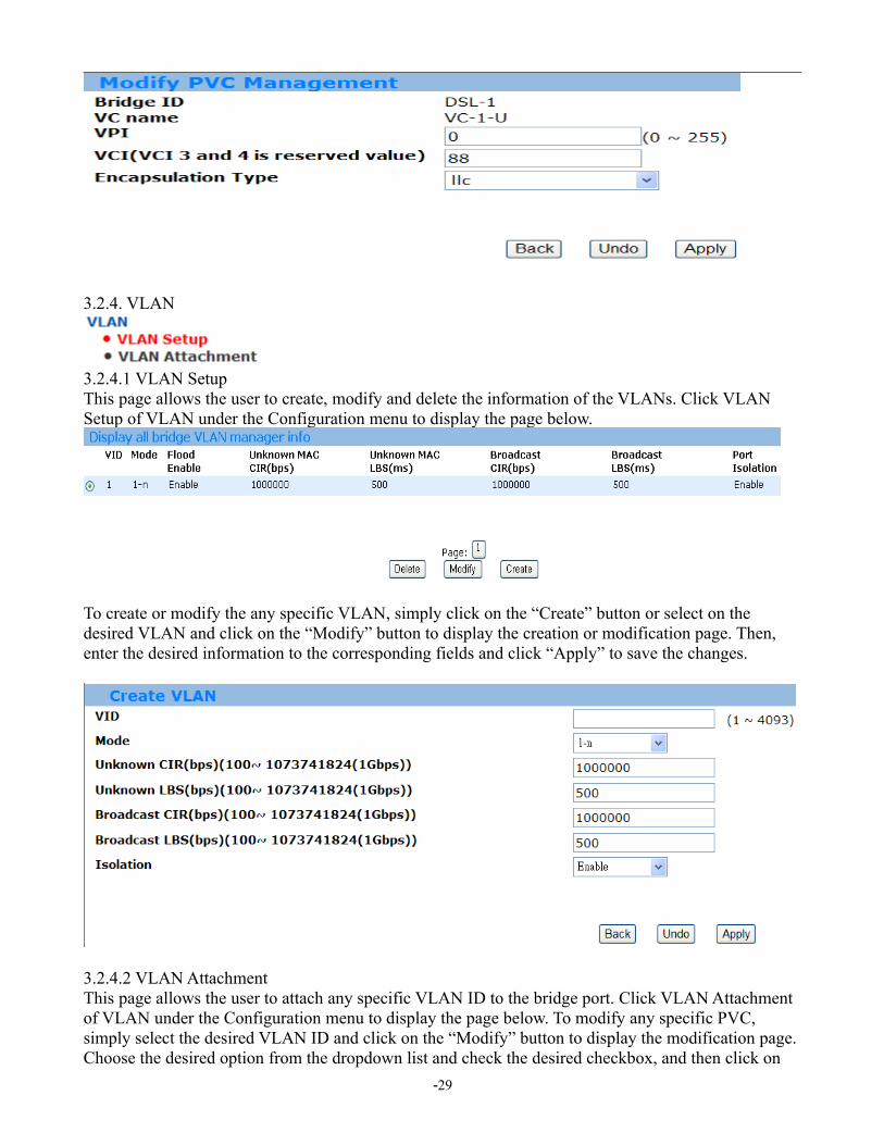
3.2.4. VLAN
3.2.4.1 VLAN SetupThis page allows the user to create, modify and delete the information of the VLANs. Click VLAN Setup of VLAN under the Configuration menu to display the page below.
To create or modify the any specific VLAN, simply click on the “Create” button or select on the desired VLAN and click on the “Modify” button to display the creation or modification page. Then, enter the desired information to the corresponding fields and click “Apply” to save the changes.
3.2.4.2 VLAN AttachmentThis page allows the user to attach any specific VLAN ID to the bridge port. Click VLAN Attachment of VLAN under the Configuration menu to display the page below. To modify any specific PVC, simply select the desired VLAN ID and click on the “Modify” button to display the modification page. Choose the desired option from the dropdown list and check the desired checkbox, and then click on
-29

the “Apply” to save the settings.
3.2.5 QoS
3.2.5.1 Ingress
3.2.5.1.1 Setup:
Create:
-30

3.2.5.1.2 Attachment
Attach
3.2.5.2 Egress
3.2.5.2.1 Contract Setup
Create:
-31
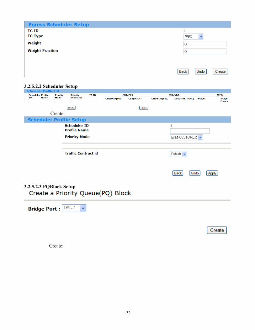
3.2.5.2.2 Scheduler Setup
Create:
3.2.5.2.3 PQBlock Setup
Create:
-32

3.2.6
Protocol Based VLAN
3.2.6.1 PBV SetupThis page displays all the rules in a PBV group. User will be able to create, modify and delete the PBV groups as well as their rules. Click PBV Setup of Protocol Based VLAN under the Configuration menu to display the page below.
First, click “Create PBV Group ID” then it will increase the PBV ID value automatic.
Then, use the dropdown list to select which PBV ID to modify. Next, click the “Create” or “Modify” button to edit the rule for that specific PBV ID as the page below. Finally, select the desired option and click “Apply” to make the changes.
Field
Description
PBV ID PBV Group Index. Valid values: 1-15 EtherType Ethernet type protocol ID. Valid values: IPv4 0x0800 | ARP 0x0806 |
802.1Q 0x8100 | IPv6 0x86dd | 802.1X 0x888e | 802.1ad 0x88a8 | OAM 0x8902 | Q-in-Q 0x9100 | LLT 0xcafe
VID VLAN ID. Valid values: 1-4093-33

3.2.6.2 PBV Attachment
This page allows the user to attach certain PBV to any specific bridge ports. Simply select which bridge port to modify first by choosing the option in the dropdown list. Then, click “Attach” button to display the attaching page as below. Again, simply use the dropdown list to select the desired PBV ID to attach and click “Apply” to save the settings.
3.3 Advanced3.3.1 Protocol Enable
3.3.1.1 Protocol Enable SetupThis page allows the user to get a list of all DFC accelerator filter groups as well as enable different protocols. Click Protocol Enable Setup of Protocol Enable under the Advanced menu to display the page below.
First, click “Create” button to display the creation page for creating DFC filters group including reserved multicast Mac, PPPoE, ARP, IGMP and DHCP packet as below. Simply use the dropdown list to select the desired options to enable and click “Apply” to create the Filter Group.
-34

3.3.1.2 Protocal AttachmentThen, attach any specific group ID by clicking on the Protocol Attachment page.
Simply check the desired option from the checkbox and click “Apply” to save the settings.
-35

3.3.2 SNMP
3.3.2.1 SNMP HOST Setup
This page allows the user to create the SNMP HOST List. Click SNMP HOST Setup of SNMP under the Advanced menu to display the page below.
-36

To add a new Host Address, simply click the “Create” button to enter the creation page as below. Enter the desired value into the corresponding fields and click “Apply” to save the settings.
3.3.2.2 SNMP TrapHost Setup This page allows the user to create the SNMP TrapHost List. Click SNMP TrapHost Setup of SNMP under the Advanced menu to display the page below.
To add a new TrapHost Address, simply click the “Create” button to enter the creation page as below. Enter the desired value into the corresponding fields and click “Apply” to save the settings.
-37

3.3.3. IGMP
3.3.3.1 IGMP ACL Setup This page allows the user to create the IGMP ACL List. Click IGMP ACL Setup of IGMP under the Advanced menu to display the page below.
To add a new IGMP ACL, simply click the “Create” button to enter the creation page as below. Enter the desired value into the corresponding fields and click “Apply” to save the settings.
3.3.3.2 IGMP Group List
3.3.3.2.1 Group List This page allows the user to create the IGMP Group List. Click Group List of IGMP Group List under the Advanced menu to display the page below.
-38
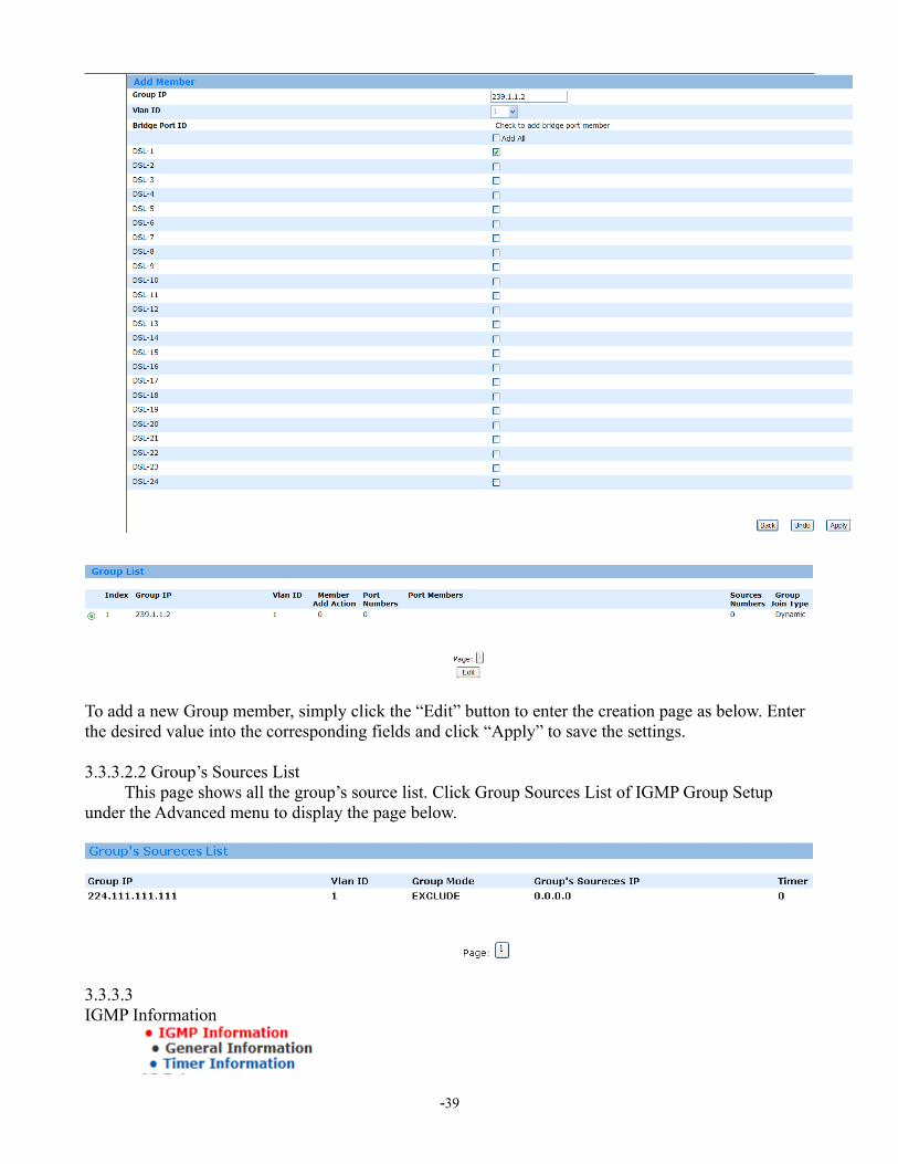
To add a new Group member, simply click the “Edit” button to enter the creation page as below. Enter the desired value into the corresponding fields and click “Apply” to save the settings.
3.3.3.2.2 Group’s Sources List This page shows all the group’s source list. Click Group Sources List of IGMP Group Setup under the Advanced menu to display the page below.
3.3.3.3 IGMP Information
-39

3.3.3.3.1General InformationThis page shows all the general information of the IGMP. Click General Information in the IGMP Information of IGMP under the Advanced menu to display the page below.
To modify the general information, click the “Modify” button to enter the modification page as below. Simply select the desired option from the dropdown list and click “Apply” to save the settings.
3.3.3.3.2 Timer Information This page shows all the Timer information of the IGMP. Click Timer Information in the IGMP Information of IGMP under the Advanced menu to display the page below.
-40
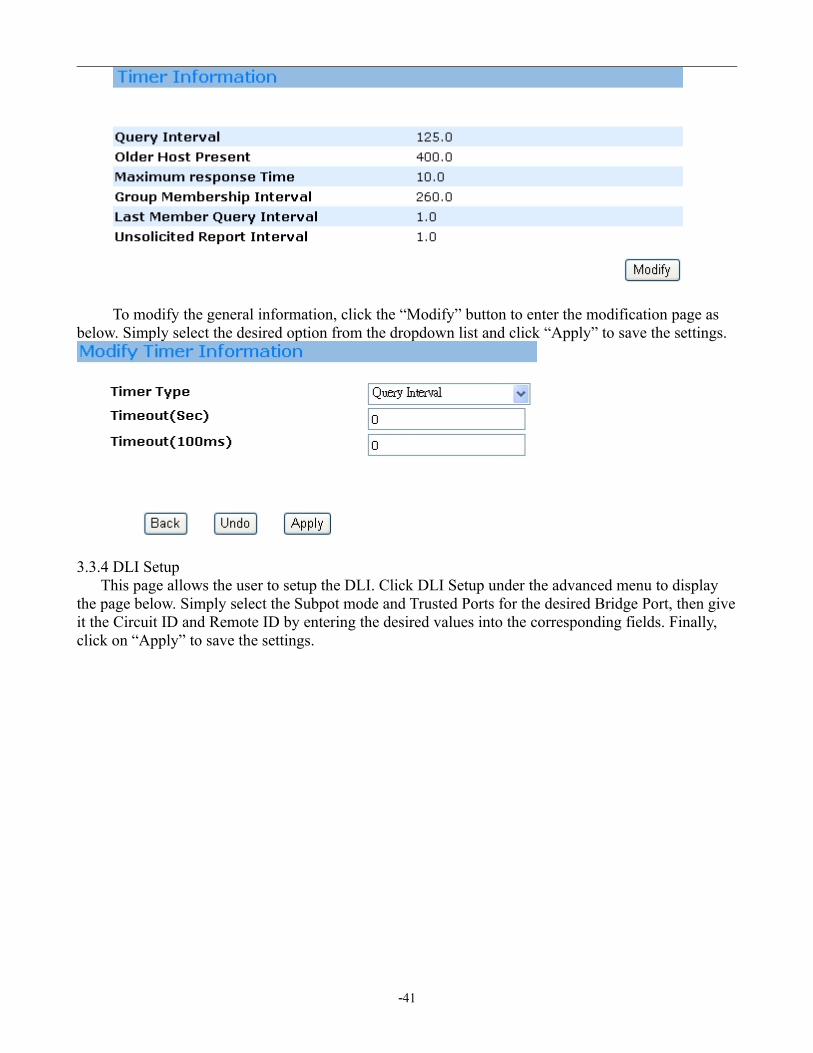
To modify the general information, click the “Modify” button to enter the modification page as below. Simply select the desired option from the dropdown list and click “Apply” to save the settings.
3.3.4 DLI Setup This page allows the user to setup the DLI. Click DLI Setup under the advanced menu to display the page below. Simply select the Subpot mode and Trusted Ports for the desired Bridge Port, then give it the Circuit ID and Remote ID by entering the desired values into the corresponding fields. Finally, click on “Apply” to save the settings.
-41
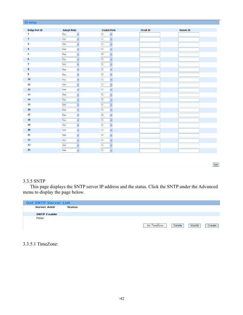
3.3.5 SNTP This page displays the SNTP server IP address and the status. Click the SNTP under the Advanced menu to display the page below.
3.3.5.1 TimeZone:
-42
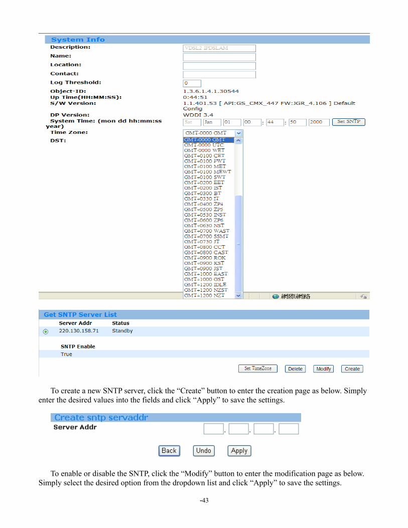
To create a new SNTP server, click the “Create” button to enter the creation page as below. Simply enter the desired values into the fields and click “Apply” to save the settings.
To enable or disable the SNTP, click the “Modify” button to enter the modification page as below. Simply select the desired option from the dropdown list and click “Apply” to save the settings.
-43

3.3.6 STP/RSTP
3.3.6.1 STP/RSTP InfoThis page displays the general information of the STP. Click the STP Info of STP/RSTP under the Advanced menu to display the page below.
To modify the STP Info, click the “Modify” button to enter the modification page as below. Simply enter the desired information and click “Apply” to save the settings.
3.3.6.2 STP/RSTP Port This page displays the general information of the STP. Click the STP Info of STP/RSTP under the
-44

Advanced menu to display the page below.
To modify the STP Ports Info, click the “Modify” button to enter the modification page as below. Simply enter the desired information and click “Apply” to save the settings.
3.3.7 802.1X
3.3.7.1 Server List This page displays the list of existing server information. Click the Server List of 802.1X under the Advanced menu to display the page below.
To create a new 802.1X server, click the “Create” button to enter the creation page as below. Simply enter the desired values into the fields and click “Apply” to save the settings.
-45
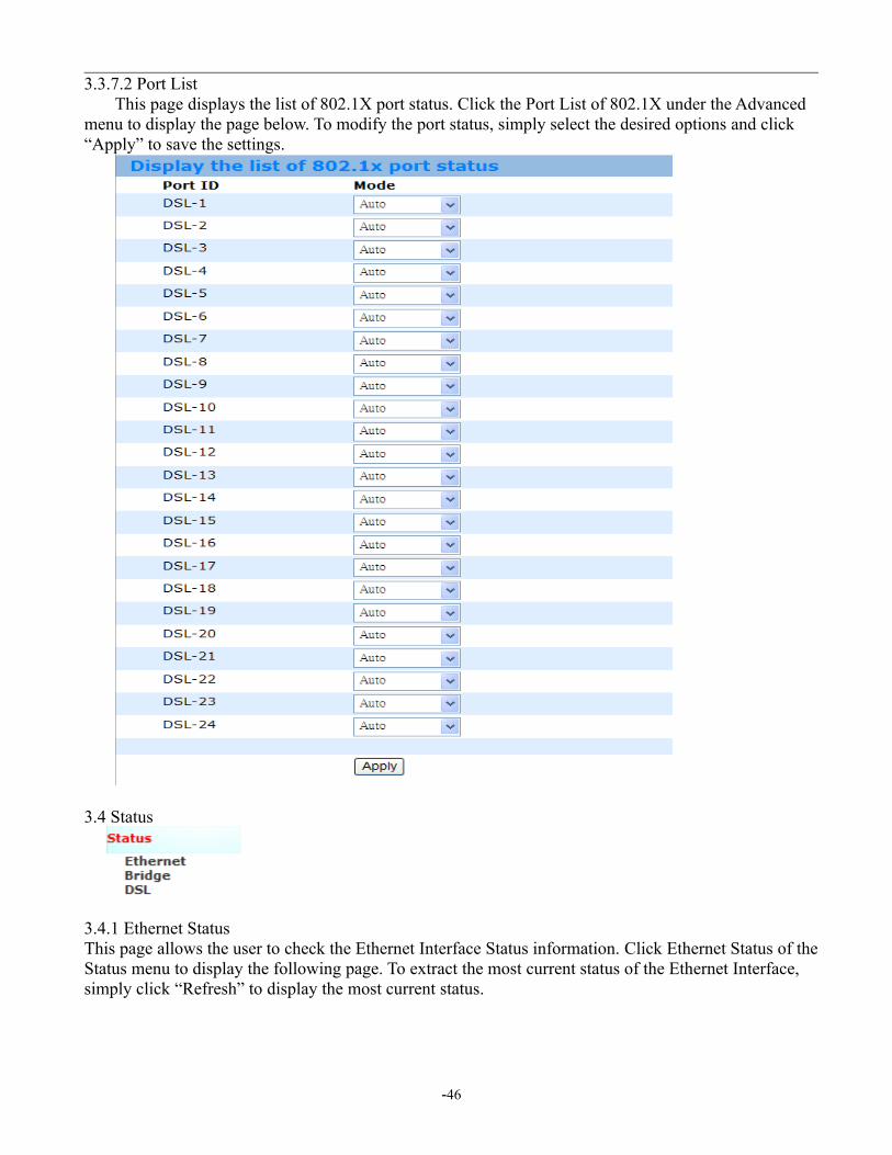
3.3.7.2 Port List This page displays the list of 802.1X port status. Click the Port List of 802.1X under the Advanced menu to display the page below. To modify the port status, simply select the desired options and click “Apply” to save the settings.
3.4 Status
3.4.1 Ethernet StatusThis page allows the user to check the Ethernet Interface Status information. Click Ethernet Status of the Status menu to display the following page. To extract the most current status of the Ethernet Interface, simply click “Refresh” to display the most current status.
-46
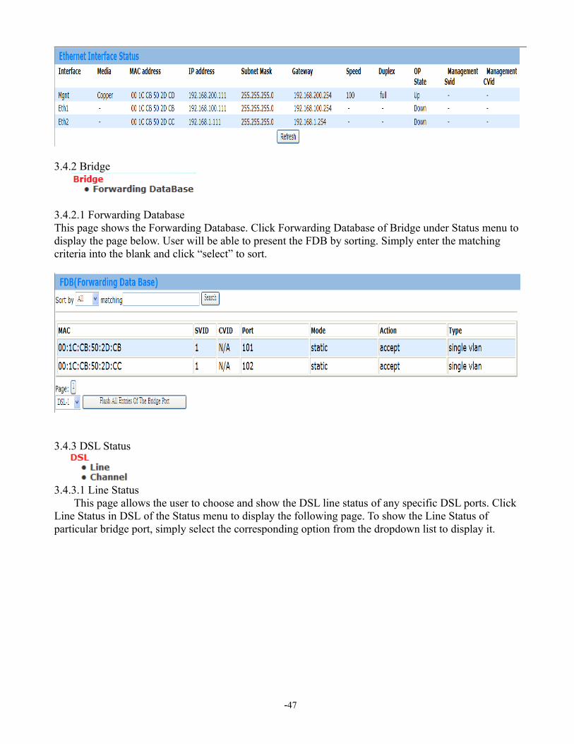
3.4.2 Bridge
3.4.2.1 Forwarding DatabaseThis page shows the Forwarding Database. Click Forwarding Database of Bridge under Status menu to display the page below. User will be able to present the FDB by sorting. Simply enter the matching criteria into the blank and click “select” to sort.
3.4.3 DSL Status
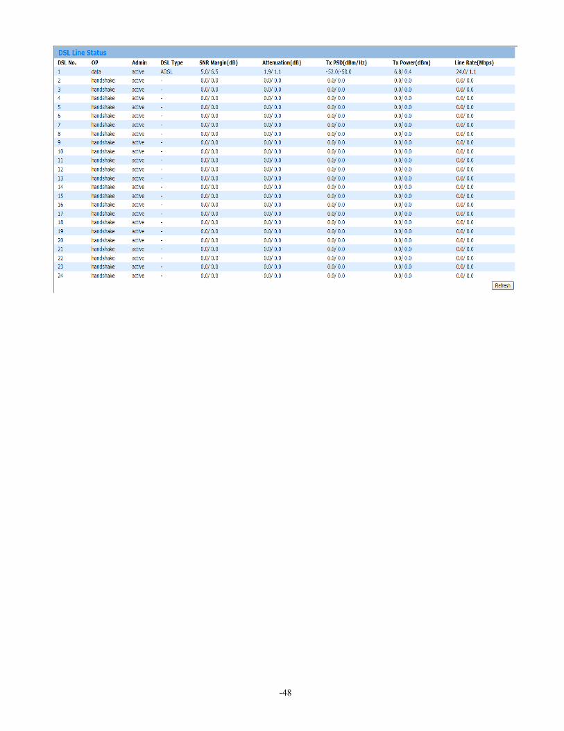
3.4.3.1 Line Status This page allows the user to choose and show the DSL line status of any specific DSL ports. Click Line Status in DSL of the Status menu to display the following page. To show the Line Status of particular bridge port, simply select the corresponding option from the dropdown list to display it.
-47
-48

3.4.3.2 Channel StatusThis page allows the user to choose and show the DSL channel status of any specific DSL ports. Click Channel Status in DSL Status of the Status menu to display the following page. To show the Channel Status of particular bridge port, simply select the corresponding option from the dropdown list to display it.
-49

3.5 Maintenance
3.5.1 Ethernet StatisticsThis page shows all the Ethernet interface statistics. Click ETH IF Statistics under Maintenance menu to present the page below. Simply select the desired ETH interface name from the dropdown list to display the information.
3.5.2 Bridge StatisticsThis page shows all the bridge statistics. Click Bridge Statistics under Maintenance menu to present the page below. Simply select the desired Bridge port ID from the dropdown list to display the information.
3.5.3 DSL Statistics
-50
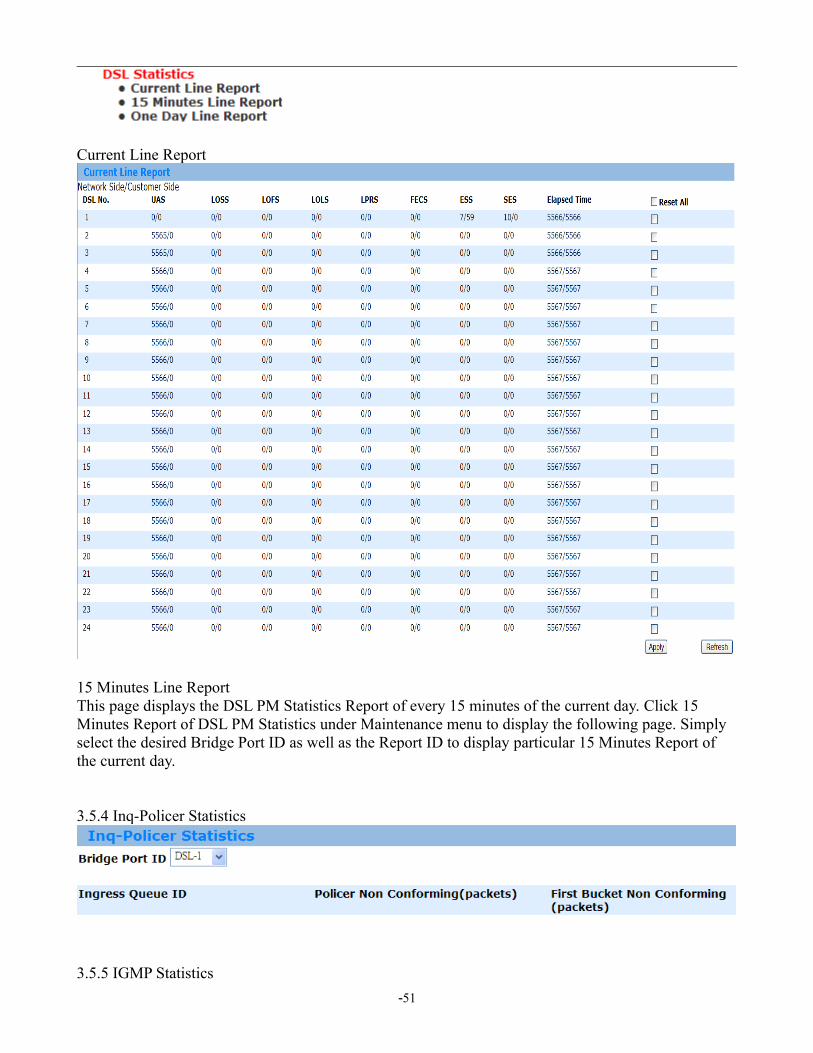
Current Line Report
15 Minutes Line ReportThis page displays the DSL PM Statistics Report of every 15 minutes of the current day. Click 15 Minutes Report of DSL PM Statistics under Maintenance menu to display the following page. Simply select the desired Bridge Port ID as well as the Report ID to display particular 15 Minutes Report of the current day.
3.5.4 Inq-Policer Statistics
3.5.5 IGMP Statistics
-51
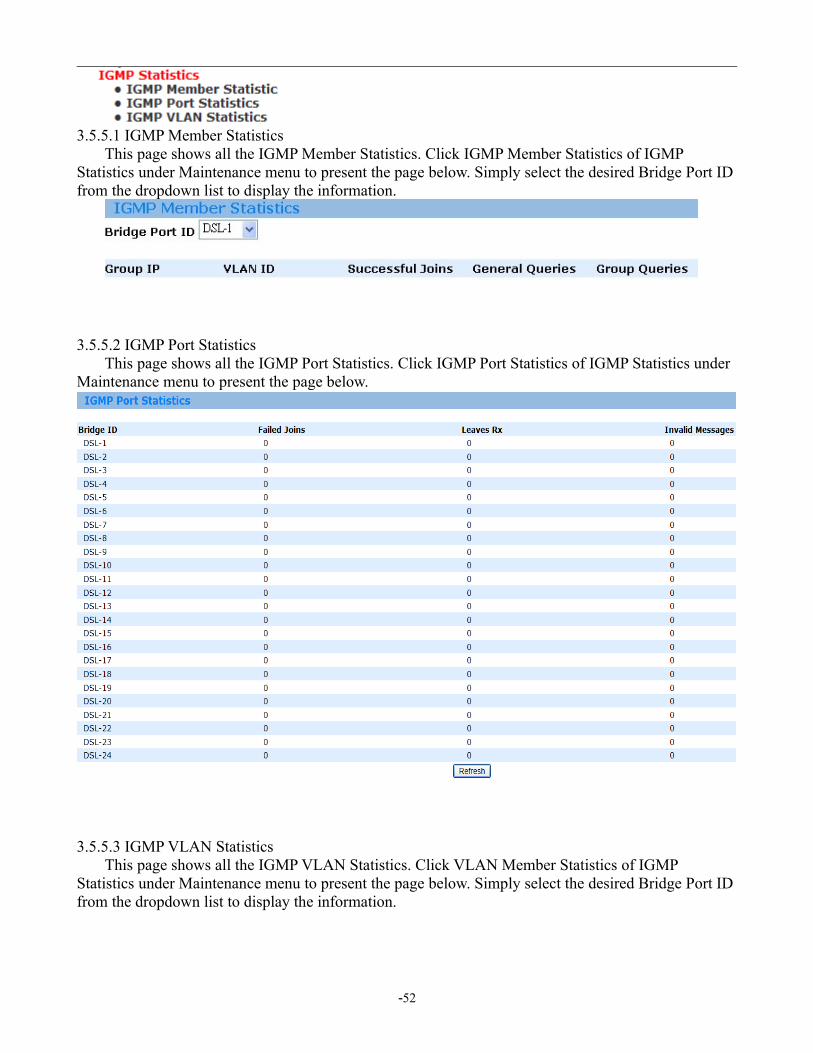
3.5.5.1 IGMP Member Statistics This page shows all the IGMP Member Statistics. Click IGMP Member Statistics of IGMP Statistics under Maintenance menu to present the page below. Simply select the desired Bridge Port ID from the dropdown list to display the information.
3.5.5.2 IGMP Port Statistics This page shows all the IGMP Port Statistics. Click IGMP Port Statistics of IGMP Statistics under Maintenance menu to present the page below.
3.5.5.3 IGMP VLAN Statistics This page shows all the IGMP VLAN Statistics. Click VLAN Member Statistics of IGMP Statistics under Maintenance menu to present the page below. Simply select the desired Bridge Port ID from the dropdown list to display the information.
-52
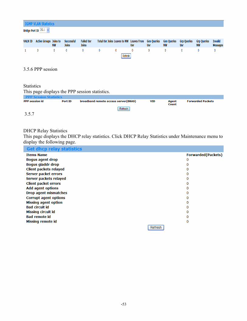
3.5.6 PPP session
StatisticsThis page displays the PPP session statistics.
3.5.7
DHCP Relay StatisticsThis page displays the DHCP relay statistics. Click DHCP Relay Statistics under Maintenance menu to display the following page.
-53