IP4319 F0313BE90QP 27 120827 - Panasonic
12
Installation Instructions Trim kit 24”cabinet (596 mm) TK712SSQP TK712SWQP © Panasonic Appliances Microwave Oven (Shanghai) Co., Ltd. 2012
Transcript of IP4319 F0313BE90QP 27 120827 - Panasonic
Installation Instructions
Trim kit
24”cabinet(596 mm)
TK712SSQP TK712SWQP
© Panasonic Appliances Microwave Oven (Shanghai) Co., Ltd. 2012
IP4319_F0313BE90QP_27_120827.indd 1IP4319_F0313BE90QP_27_120827.indd 1 2012-8-27 13:17:132012-8-27 13:17:13
1
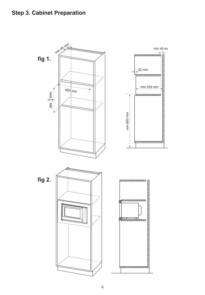
1. This trim kit can be installed into a cabinet.The cabinet opening must have the following internal dimensions as shown in fig 1, p 4.
A vent is required at the rear of the cabinet. It should travel the full height of the cabinet and the cabinet should not be obstructed. Minimum dimension of vent: 45 mm x 600 mm (fig 1, p 4).
MINIMUM INSTALLATION HEIGHT 850 MM.
2. Electrical Connections The appliance is supplied with a mains plug attached and should only be connected into an earthed socket that has been installed according to the relevant safety regulations. If the plug is no longer accessible after the appliance has been built into the cabinet, a dual pole isolator must be installed to conform to the relevant safety standards.
3. Appliance shall be provided with means for disconnection from the supply mains having a contact separation in all poles that provide full disconnection under overvoltage Ⅲ conditions, such means must be incorporated in the fixed wiring in accordance with the wiring rules and accessible.
4. It is essential that the cabinet is fixed to the wall for stability. The shelf must be able to support a weight of 30 kg.
5. If the microwave oven is to be removed from the kitchen cabinet and used free standing, the built in parts must be removed, and the oven returned to its original condition. Keep these installation instructions for future reference so the installation process can be reversed.
TAKE CARE NOT TO KINK OR TRAP THE MICROWAVE ELECTRICAL CABLE.
The diagram may vary from the actual unit and is only for your reference.
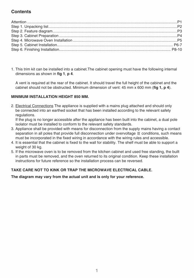
Contents
Attention .............................................................................................................................................P1Step 1. Unpacking list .........................................................................................................................P2Step 2. Feature diagram .....................................................................................................................P3Step 3. Cabinet Preparation ...............................................................................................................P4Step 4. Microwave Oven Installation ..................................................................................................P5Step 5. Cabinet Installation............................................................................................................. P6-7Step 6. Finishing Installation......................................................................................................... P8-10
IP4319_F0313BE90QP_27_120827.indd Sec1:1IP4319_F0313BE90QP_27_120827.indd Sec1:1 2012-8-27 13:17:142012-8-27 13:17:14
2
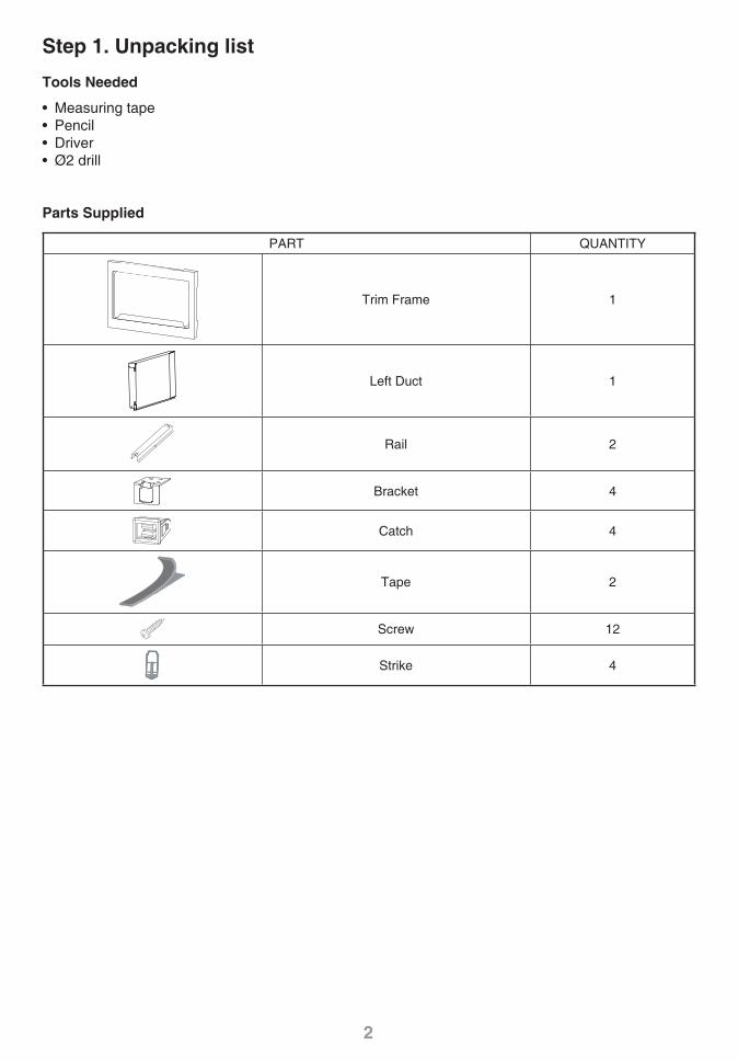
Step 1. Unpacking list
Tools Needed
• Measuring tape• Pencil• Driver• Ø2 drill
Parts Supplied
PART QUANTITY
Trim Frame 1
Left Duct 1
Rail 2
Bracket 4
Catch 4
Tape 2
Screw 12
Strike 4
IP4319_F0313BE90QP_27_120827.indd Sec1:2IP4319_F0313BE90QP_27_120827.indd Sec1:2 2012-8-27 13:17:142012-8-27 13:17:14
3
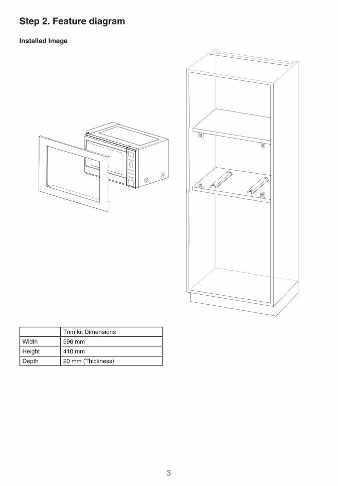
Step 2. Feature diagram
Installed Image
Trim kit Dimensions
Width 596 mm
Height 410 mm
Depth 20 mm (Thickness)
IP4319_F0313BE90QP_27_120827.indd Sec1:3IP4319_F0313BE90QP_27_120827.indd Sec1:3 2012-8-27 13:17:142012-8-27 13:17:14
4
min 45 mm
min
850
mm
min 533 mm
22 mm
600 mm
395 -4
0
mm
min 45 mm
fig 1.
fig 2.
Step 3. Cabinet Preparation
IP4319_F0313BE90QP_27_120827.indd Sec1:4IP4319_F0313BE90QP_27_120827.indd Sec1:4 2012-8-27 13:17:142012-8-27 13:17:14
5
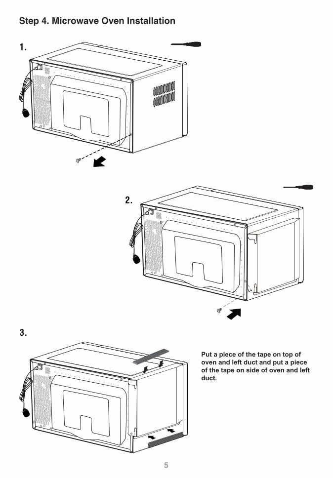
Step 4. Microwave Oven Installation
1.
3.
2.
Put a piece of the tape on top of oven and left duct and put a piece of the tape on side of oven and left duct.
IP4319_F0313BE90QP_27_120827.indd Sec1:5IP4319_F0313BE90QP_27_120827.indd Sec1:5 2012-8-27 13:17:142012-8-27 13:17:14
6
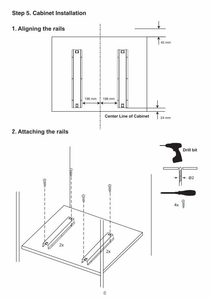
196 mm 196 mm
24 mm
45 mm
1. Aligning the rails
2. Attaching the rails
Center Line of Cabinet
Step 5. Cabinet Installation
4x
ø2
2x
2x
Drill bit
IP4319_F0313BE90QP_27_120827.indd Sec1:6IP4319_F0313BE90QP_27_120827.indd Sec1:6 2012-8-27 13:17:142012-8-27 13:17:14
7
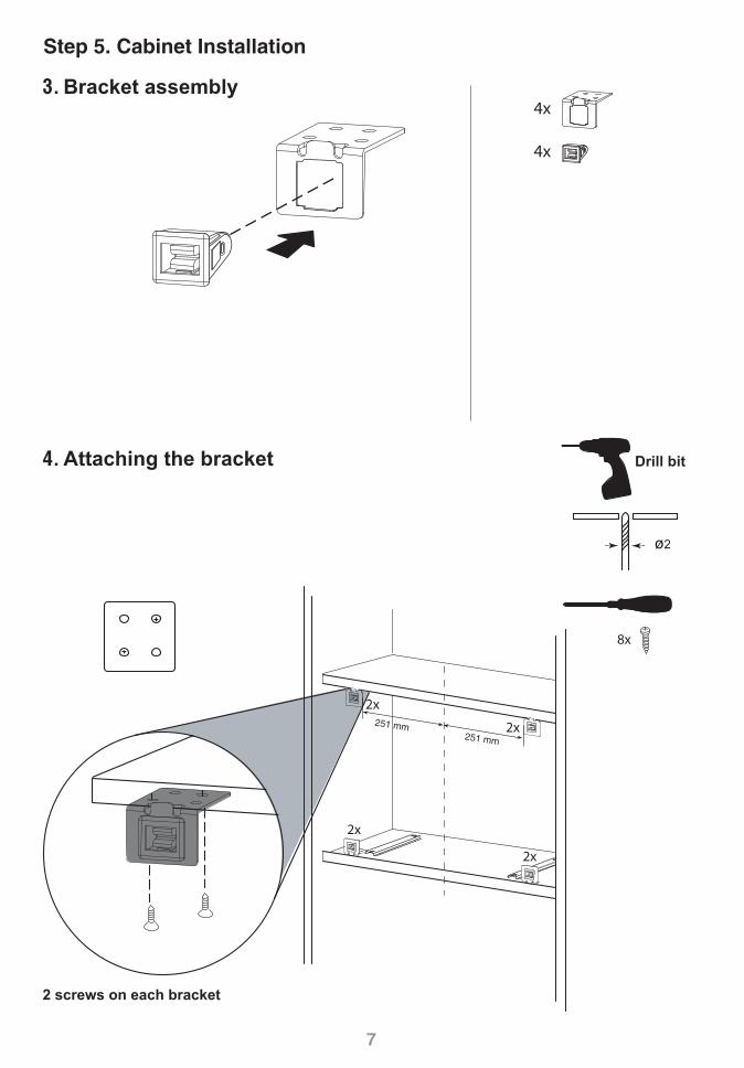
4x
4x
2x
2x
8x
ø2
2x
2x251 mm251 mm
4. Attaching the bracket
3. Bracket assembly
Step 5. Cabinet Installation
Drill bit
2 screws on each bracket
IP4319_F0313BE90QP_27_120827.indd Sec1:7IP4319_F0313BE90QP_27_120827.indd Sec1:7 2012-8-27 13:17:142012-8-27 13:17:14

88
4X
Step 6. Finishing Installation
Trim Frame
1. Inserting strikes 1-1
1-2
IP4319_F0313BE90QP_27_120827.indd Sec1:8IP4319_F0313BE90QP_27_120827.indd Sec1:8 2012-8-27 13:17:142012-8-27 13:17:14
9
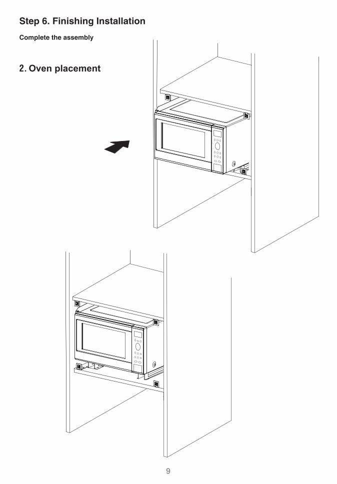
Step 6. Finishing Installation
Complete the assembly
2. Oven placement
IP4319_F0313BE90QP_27_120827.indd Sec1:9IP4319_F0313BE90QP_27_120827.indd Sec1:9 2012-8-27 13:17:142012-8-27 13:17:14
10
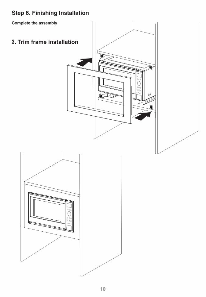
Step 6. Finishing Installation
Complete the assembly
10
3. Trim frame installation
IP4319_F0313BE90QP_27_120827.indd Sec1:10IP4319_F0313BE90QP_27_120827.indd Sec1:10 2012-8-27 13:17:152012-8-27 13:17:15

F0313BE90QPIP0812-0
Printed in China
IP4319_F0313BE90QP_27_120827.indd Sec1:11IP4319_F0313BE90QP_27_120827.indd Sec1:11 2012-8-27 13:17:152012-8-27 13:17:15