IP - The Internet Protocolmagda/cs620/ch4.pdfIP and the Internet Architecture 3 Network Layer Link...
50
IP - The Internet Protocol Magda El Zarki Dept. of CS UC Irvine Email: [email protected] http://www.ics.uci.edu/~magda 1
Transcript of IP - The Internet Protocolmagda/cs620/ch4.pdfIP and the Internet Architecture 3 Network Layer Link...

IP - The Internet Protocol Magda El Zarki
Dept. of CS UC Irvine
Email: [email protected] http://www.ics.uci.edu/~magda
1
Overview
IP (Internet Protocol) is a Network Layer Protocol.
Several versions – most popular (IPv4). It is specified in RFC 891.
Gaining popularity is IPv6 due to increased addressing space and security handling.
2

IP and the Internet Architecture
3
NetworkLayer
Link Layer
IP
ARP NetworkAccess
Media
ICMP IGMP
TransportLayer
TCP UDP
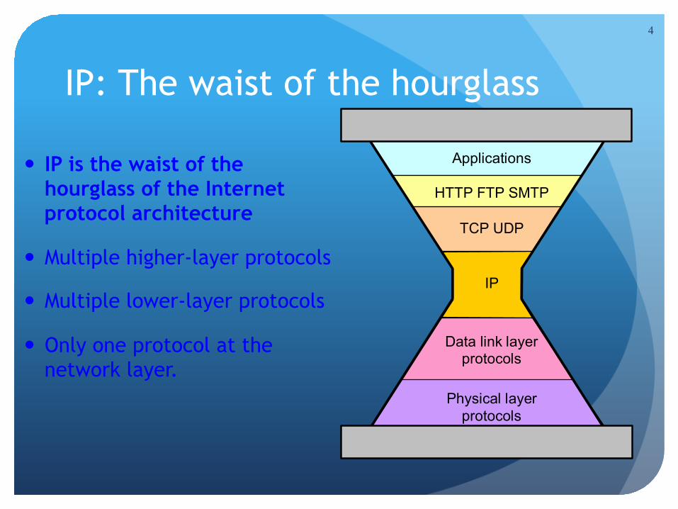
IP: The waist of the hourglass
IP is the waist of the hourglass of the Internet protocol architecture
Multiple higher-layer protocols
Multiple lower-layer protocols
Only one protocol at the network layer.
4
Applications
HTTP FTP SMTP
TCP UDP
IP
Data link layer protocols
Physical layer protocols
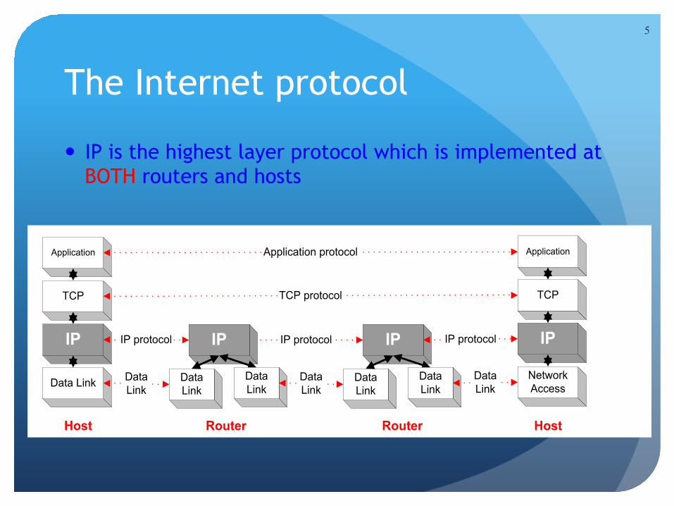
The Internet protocol
IP is the highest layer protocol which is implemented at BOTH routers and hosts
5
Application
TCP
IP
Data Link
Application
TCP
IP
NetworkAccess
Application protocol
TCP protocol
IP protocol IP protocol
DataLink
DataLink
IP
DataLink
DataLink
IP
DataLink
DataLink
DataLink
IP protocol
RouterRouter HostHost
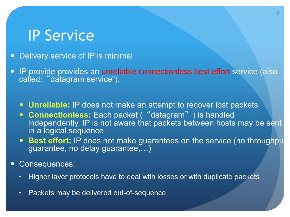
IP Service Delivery service of IP is minimal
IP provide provides an unreliable connectionless best effort service (also called:“datagram service”).
Unreliable: IP does not make an attempt to recover lost packets Connectionless: Each packet (“datagram”) is handled
independently. IP is not aware that packets between hosts may be sent in a logical sequence
Best effort: IP does not make guarantees on the service (no throughput guarantee, no delay guarantee,…)
Consequences: • Higher layer protocols have to deal with losses or with duplicate packets
• Packets may be delivered out-of-sequence
6

IP Service
IP supports the following services: one-to-one (unicast) one-to-all (broadcast) one-to-several (multicast)
IP multicast also supports a many-to-many service.
IP multicast requires support of other protocols (IGMP, multicast routing)
7
unicast broadcast multicast

IP Datagram Format
20 bytes ≤ Header Size < 24 x 4 bytes = 60 bytes
20 bytes ≤ Total Length < 216 bytes = 65536 bytes
8
ECNversion headerlength DS total length (in bytes)
Identification Fragment offset
source IP address
destination IP address
options (0 to 40 bytes)
payload
4 bytes
time-to-live (TTL) protocol header checksum
bit # 0 15 23 248 317 16
0 MF
DF

IP Datagram Format Question: In which order are the bytes of an IP datagram
transmitted?
Answer: Transmission is row by row For each row:
1. First transmit bits 0-7 2. Then transmit bits 8-15 3. Then transmit bits 16-23 4. Then transmit bits 24-31
This is called network byte order or big endian byte ordering.
Note: some computers store 32-bit words in little endian format.
9

Fields of the IP Header
Version (4 bits): current version is 4, next version will be 6.
Header length (4 bits): length of IP header, in multiples of 4 bytes
DS/ECN field (1 byte) This field was previously called as Type-of-Service (TOS) field.
The role of this field has been re-defined, but is “backwards compatible” to TOS interpretation
Differentiated Service (DS) (6 bits): Used to specify service level (currently not supported in the
Internet)
Explicit Congestion Notification (ECN) (2 bits): Feedback mechanism used by TCP
10
Fields of the IP Header
Identification (16 bits): Unique identification of a datagram from a host. Incremented whenever a datagram is transmitted
Flags (3 bits): First bit always set to 0 DF bit (Do not fragment) MF bit (More fragments) Will be explained later Fragmentation
11

Fields of the IP Header
Time To Live (TTL) (1 byte): Specifies longest paths before datagram is dropped Role of TTL field: Ensure that packet is eventually dropped
when a routing loop occurs Used as follows: Sender sets the value (e.g., 16) Each router decrements the value by 1 When the value reaches 0, the datagram is dropped
12
Fields of the IP Header
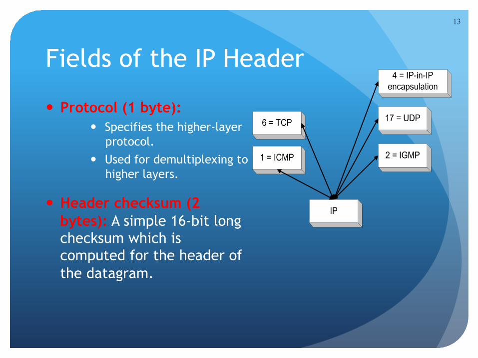
Protocol (1 byte): Specifies the higher-layer
protocol. Used for demultiplexing to
higher layers.
Header checksum (2 bytes): A simple 16-bit long checksum which is computed for the header of the datagram.
13
IP
1 = ICMP 2 = IGMP
6 = TCP 17 = UDP
4 = IP-in-IPencapsulation

Fields of the IP Header
Options: Security restrictions
Record Route: each router that processes the packet adds its IP address to the header.
Timestamp: each router that processes the packet adds its IP address and time to the header.
(loose) Source Routing: specifies a list of routers that must be traversed.
(strict) Source Routing: specifies a list of the only routers that can be traversed.
Padding: Padding bytes are added to ensure that header ends on a 4-byte boundary
14
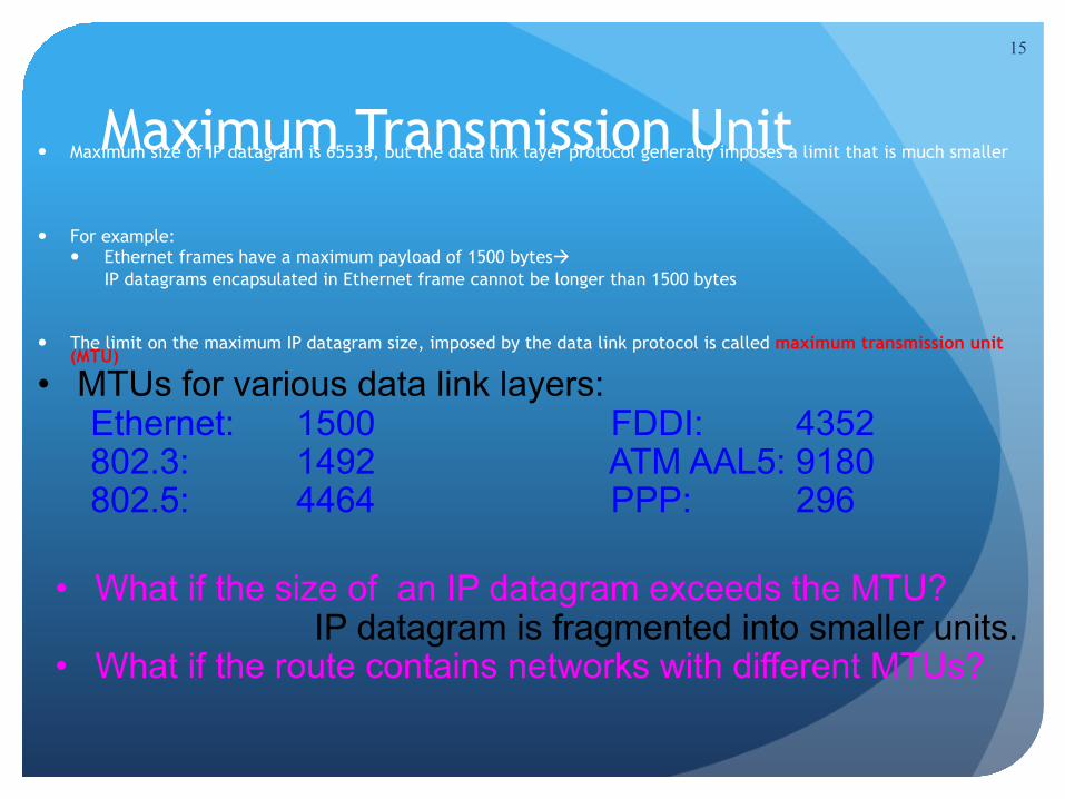
Maximum Transmission Unit Maximum size of IP datagram is 65535, but the data link layer protocol generally imposes a limit that is much smaller
For example: Ethernet frames have a maximum payload of 1500 bytes
IP datagrams encapsulated in Ethernet frame cannot be longer than 1500 bytes
The limit on the maximum IP datagram size, imposed by the data link protocol is called maximum transmission unit (MTU)
15
• What if the size of an IP datagram exceeds the MTU? IP datagram is fragmented into smaller units.
• What if the route contains networks with different MTUs?
• MTUs for various data link layers: Ethernet: 1500 FDDI: 4352 802.3: 1492 ATM AAL5: 9180 802.5: 4464 PPP: 296
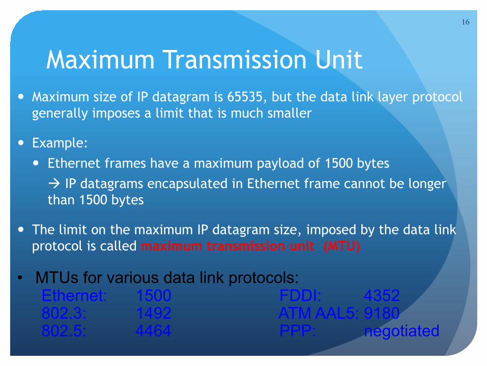
Maximum Transmission Unit Maximum size of IP datagram is 65535, but the data link layer protocol
generally imposes a limit that is much smaller
Example: Ethernet frames have a maximum payload of 1500 bytes
IP datagrams encapsulated in Ethernet frame cannot be longer than 1500 bytes
The limit on the maximum IP datagram size, imposed by the data link protocol is called maximum transmission unit (MTU)
16
• MTUs for various data link protocols: Ethernet: 1500 FDDI: 4352 802.3: 1492 ATM AAL5: 9180 802.5: 4464 PPP: negotiated

IP Fragmentation
FDDIRing
RouterHost A Host B
Ethernet
17
MTUs: FDDI: 4352 Ethernet: 1500 • Fragmentation:
• IP router splits the datagram into several datagrams • Fragments are reassembled at receiver
• What if the size of an IP datagram exceeds the MTU? • IP datagram is fragmented into smaller units.
• What if the route contains networks with different MTUs? • IP datagram is fragmented into smaller and smaller units
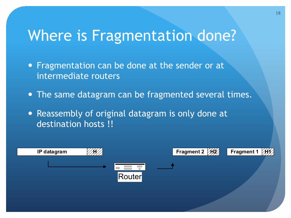
Where is Fragmentation done?
Fragmentation can be done at the sender or at intermediate routers
The same datagram can be fragmented several times.
Reassembly of original datagram is only done at destination hosts !!
18
Router
IP datagram H Fragment 1 H1Fragment 2 H2
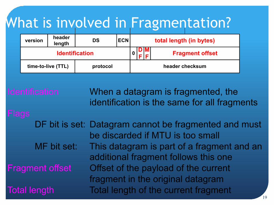
What is involved in Fragmentation? ECNversion header
length DS total length (in bytes)
Identification Fragment offset
time-to-live (TTL) protocol header checksum
0 MF
DF
19
Identification When a datagram is fragmented, the identification is the same for all fragments
Flags DF bit is set: Datagram cannot be fragmented and must be discarded if MTU is too small MF bit set: This datagram is part of a fragment and an additional fragment follows this one
Fragment offset Offset of the payload of the current fragment in the original datagram
Total length Total length of the current fragment
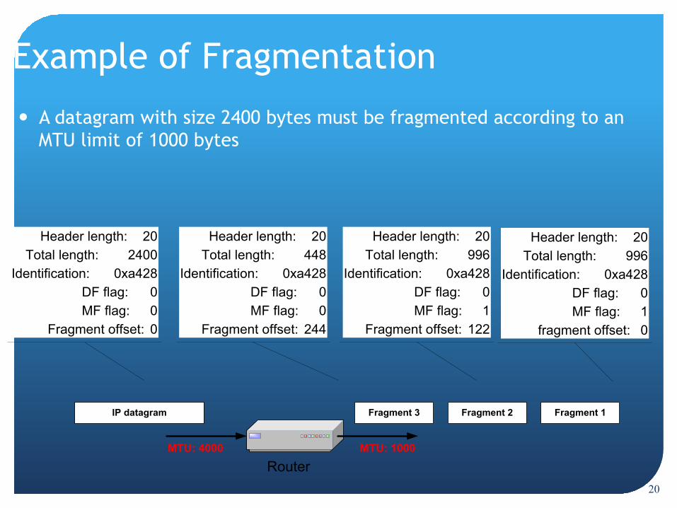
Example of Fragmentation
A datagram with size 2400 bytes must be fragmented according to an MTU limit of 1000 bytes
IP datagram
Router
Fragment 2Fragment 3
MTU: 1000MTU: 4000
Fragment 1
Header length: 20Total length: 2400
Identification: 0xa428DF flag: 0MF flag: 0
Fragment offset: 0
20
Header length: 20Total length: 996
Identification: 0xa428DF flag: 0MF flag: 1
fragment offset: 0
Header length: 20Total length: 996
Identification: 0xa428DF flag: 0MF flag: 1
Fragment offset: 122
Header length: 20Total length: 448
Identification: 0xa428DF flag: 0MF flag: 0
Fragment offset: 244
21
Internet Control Message Protocol (ICMP)
22
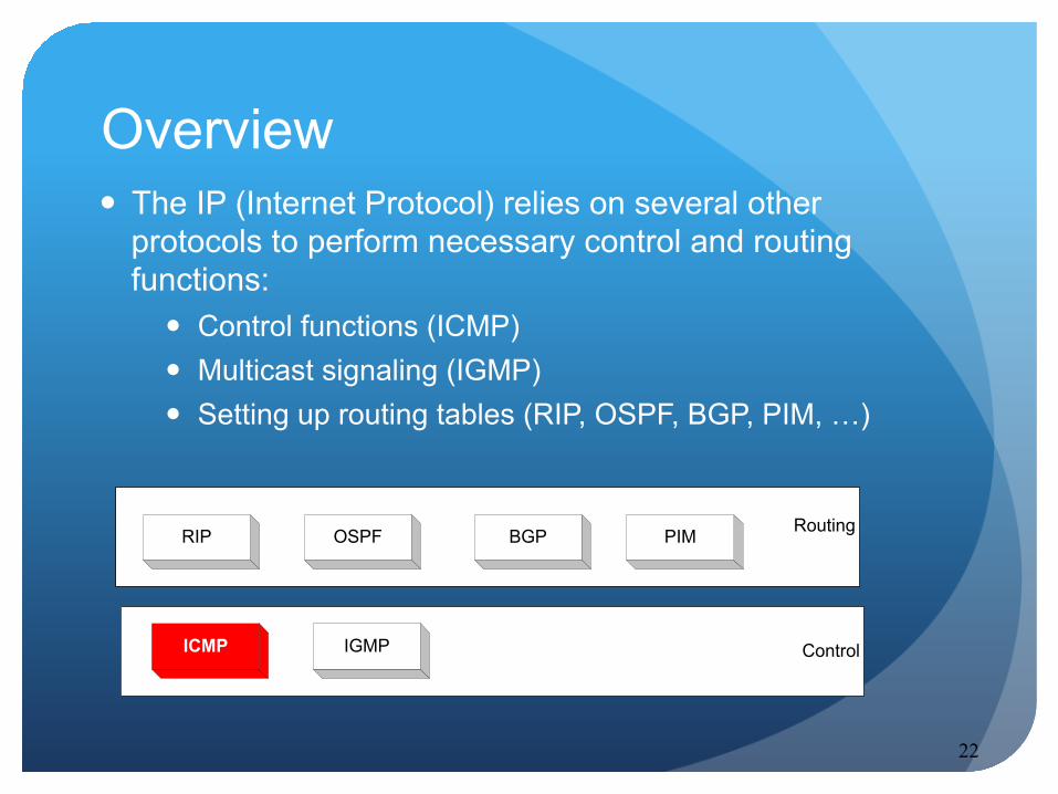
The IP (Internet Protocol) relies on several other protocols to perform necessary control and routing functions:
Control functions (ICMP) Multicast signaling (IGMP) Setting up routing tables (RIP, OSPF, BGP, PIM, …)
Control
Routing
ICMP IGMP
RIP OSPF BGP PIM
Overview

23
ICMP The Internet Control Message Protocol (ICMP) is a helper
protocol that supports IP with: Error reporting Simple queries
ICMP messages are encapsulated as IP datagrams:
IP header ICMP message
IP payload
24
ICMP message format
additional informationor
0x00000000
type code checksum
bit # 0 15 23 248 317 16
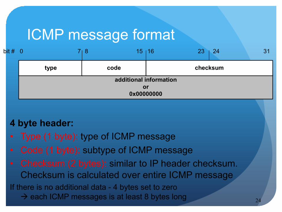
4 byte header: • Type (1 byte): type of ICMP message • Code (1 byte): subtype of ICMP message • Checksum (2 bytes): similar to IP header checksum.
Checksum is calculated over entire ICMP message If there is no additional data - 4 bytes set to zero
each ICMP messages is at least 8 bytes long
25
ICMP Query message
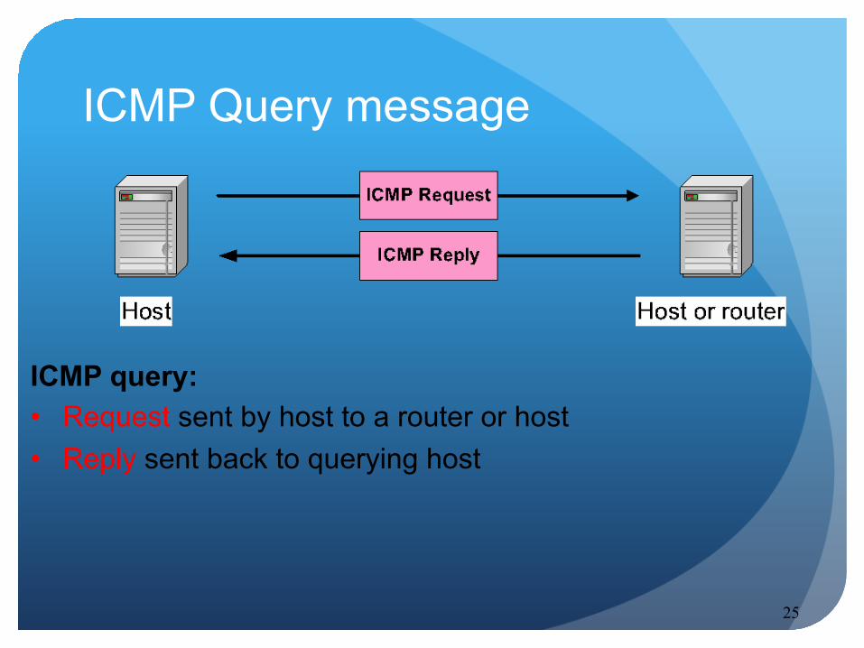
ICMP query: • Request sent by host to a router or host • Reply sent back to querying host
26
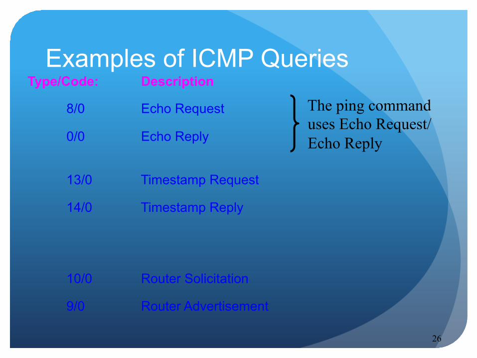
Examples of ICMP Queries Type/Code: Description
8/0 Echo Request
0/0 Echo Reply
13/0 Timestamp Request
14/0 Timestamp Reply
10/0 Router Solicitation
9/0 Router Advertisement
The ping command uses Echo Request/ Echo Reply
27
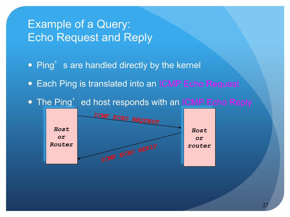
Ping’s are handled directly by the kernel
Each Ping is translated into an ICMP Echo Request
The Ping’ed host responds with an ICMP Echo Reply
Example of a Query: Echo Request and Reply
Host or
Router
ICMP ECHO REQUEST Host or
router
ICMP ECH
O REPLY

28
Example of a Query: ICMP Timestamp
A system (host or router) asks another system for the current time.
Time is measured in milliseconds after midnight UTC (Universal Coordinated Time) of the current day
Sender sends a request, receiver responds with reply Type
(= 17 or 18)Code(=0) Checksum
32-bit sender timestamp
identifier sequence number
32-bit receive timestamp
32-bit transmit timestamp
Sender
Receiver
Timestamp Request
Timestamp Reply

29
ICMP Error message
• ICMP error messages report error conditions • Typically sent when a datagram is discarded • Error message is often passed from ICMP to the
application program

30
ICMP Error message
• ICMP error messages include the complete IP header and the first 8 bytes of the payload (typically: UDP, TCP)
Unused (0x00000000)
IP header ICMP header IP header 8 bytes of payload
ICMP Message
from IP datagram that triggered the error
type code checksum

31
Common ICMP Error messages
Type Code Description 3
0–15 Destination
unreachable Notification that an IP datagram could not be forwarded and was dropped. The code field contains an explanation.
5 0–3 Redirect Informs about an alternative route for the datagram and should result in a routing table update. The code field explains the reason for the route change.
11 0, 1 Time exceeded
Sent when the TTL field has reached zero (Code 0) or when there is a timeout for the reassembly of segments (Code 1)
12 0, 1 Parameter problem
Sent when the IP header is invalid (Code 0) or when an IP header option is missing (Code 1)

32
Some subtypes of the “Destination Unreachable”
Code Description Reason for Sending
0 Network Unreachable
No routing table entry is available for the destination network.
1 Host Unreachable
Destination host should be directly reachable, but does not respond to ARP Requests.
2 Protocol Unreachable
The protocol in the protocol field of the IP header is not supported at the destination.
3 Port Unreachable
The transport protocol at the destination host cannot pass the datagram to an application.
4 Fragmentation Needed and DF Bit Set
IP datagram must be fragmented, but the DF bit in the IP header is set.
33
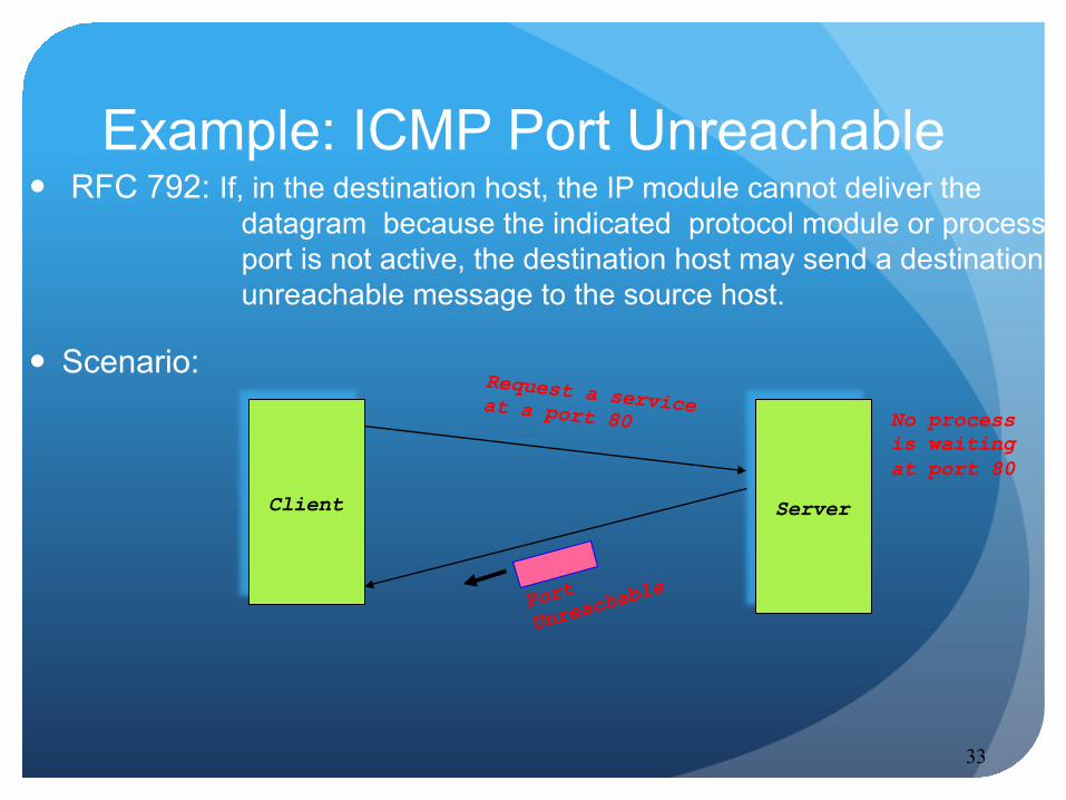
Example: ICMP Port Unreachable RFC 792: If, in the destination host, the IP module cannot deliver the
datagram because the indicated protocol module or process port is not active, the destination host may send a destination unreachable message to the source host.
Scenario:
Client
Request a service at a port 80
Server
No process is waiting at port 80
Port
Unreacha
ble
34
IP Forwarding
35
Internet is a collection of networks
IP provides an end-to-end delivery service between hosts
The delivery service is realized with the help of IP routers
Overview
36
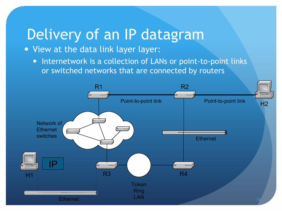
Delivery of an IP datagram
Ethernet
TokenRingLANEthernet
H1
R1 R2
R3 R4
H2
Network ofEthernetswitches
Point-to-point link Point-to-point link
IP
View at the data link layer layer: Internetwork is a collection of LANs or point-to-point links
or switched networks that are connected by routers
37
H1
R1 R2
R3 R4
H210.2.1.0/24
20.1.0.0/1610.1.2.0/24
10.1.0.0/24 10.3.0.0/16
20.2.1.0/28
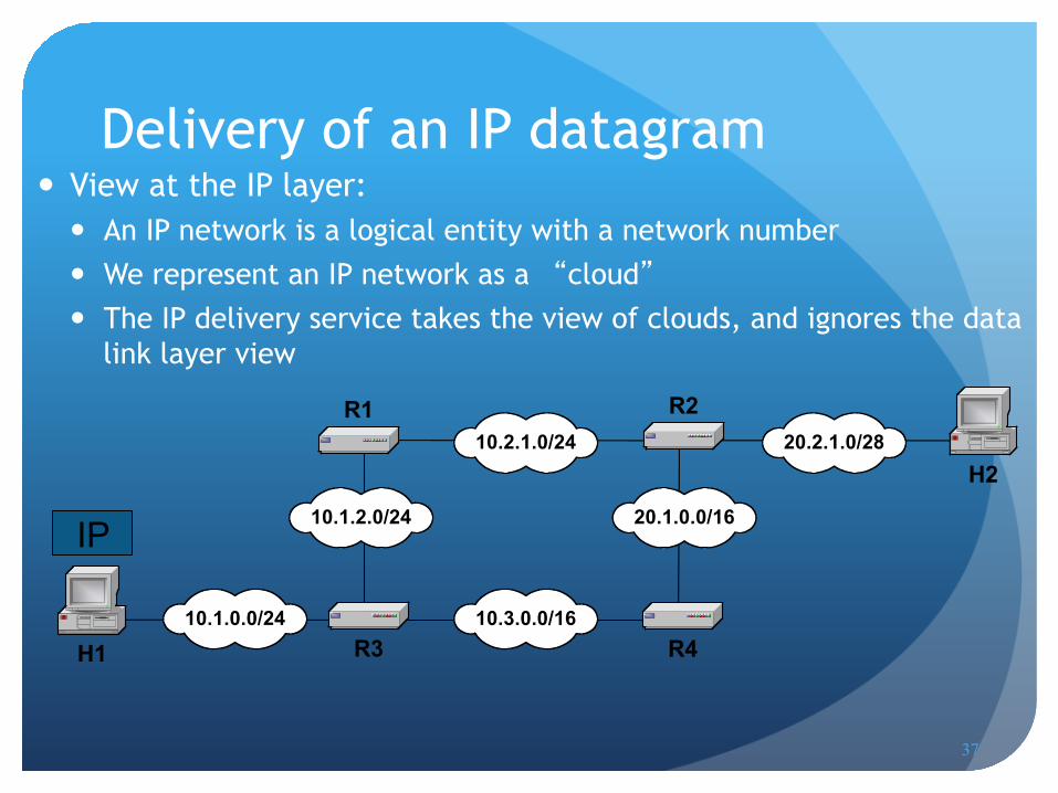
Delivery of an IP datagram
IP
View at the IP layer: An IP network is a logical entity with a network number We represent an IP network as a “cloud” The IP delivery service takes the view of clouds, and ignores the data
link layer view
38
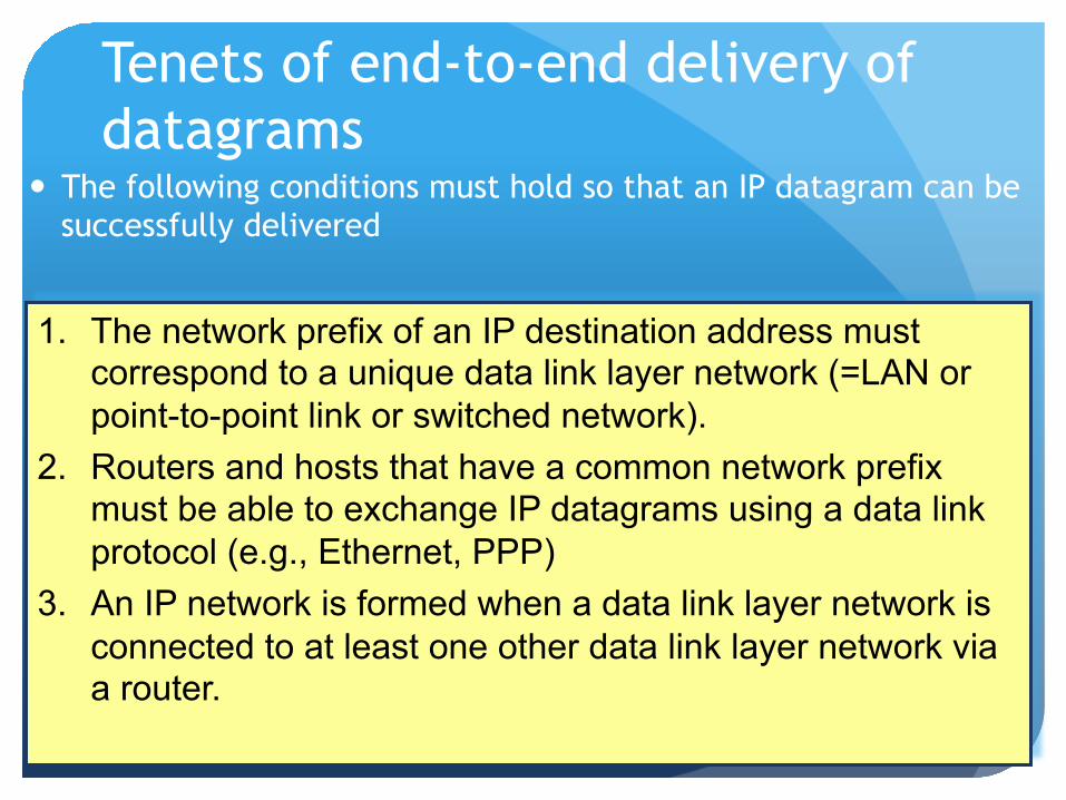
Tenets of end-to-end delivery of datagrams
The following conditions must hold so that an IP datagram can be successfully delivered
1. The network prefix of an IP destination address must correspond to a unique data link layer network (=LAN or point-to-point link or switched network).
2. Routers and hosts that have a common network prefix must be able to exchange IP datagrams using a data link protocol (e.g., Ethernet, PPP)
3. An IP network is formed when a data link layer network is connected to at least one other data link layer network via a router.

39
Routing tables Each router and each host keeps a routing table which tells
the router how to process an outgoing packet
Main columns: 1. Destination address: where is the IP datagram going to? 2. Next hop or interface: how to send the IP datagram?
Routing tables are set so that a datagram gets closer to the its destination
Destination Next Hop 20.2.1.0/28 10.1.0.0/24 10.1.2.0/24 10.2.1.0/24 10.3.1.0/24 20.1.0.0/16
R4 direct direct R4 direct R4
Routing table of a host or router IP datagrams can either be directly delivered (“direct”) or are sent to a next hop router (“R4”)

40
Delivery with routing tables
Destination Next Hop 10.1.0.0/24 10.1.2.0/24 10.2.1.0/24 10.3.1.0/24 20.1.0.0/16 20.2.1.0/28
direct R3 R3 R3 R3 R3
H1
R1 R2
R3 R4
H210.2.1.0/24
20.1.0.0/1610.1.2.0/24
10.1.0.0/24 10.3.0.0/16
20.2.1.0/28
20.2.1.2/28
Destination Next Hop 10.1.0.0/24 10.1.2.0/24 10.2.1.0/24 10.3.1.0/24 20.1.0.0/16 20.2.1.0/28
direct direct R4 direct R4 R4
Destination Next Hop 10.1.0.0/24 10.1.2.0/24 10.2.1.0/24 10.3.1.0/24 20.1.0.0/16 20.2.1.0/28
R3 R3 R2 direct direct R2
Destination Next Hop 10.1.0.0/24 10.1.2.0/24 10.2.1.0/24 10.3.1.0/24 20.2.0.0/16 30.1.1.0/28
R3 direct direct R3 R2 R2
Destination Next Hop 10.1.0.0/24 10.1.2.0/24 10.2.1.0/24 10.3.1.0/24 20.1.0.0/16 20.2.1.0/28
R1 R1 direct R4 direct direct
Destination Next Hop 10.1.0.0/24 10.1.2.0/24 10.2.1.0/24 10.3.1.0/24 20.1.0.0/16 20.2.1.0/28
R2 R2 R2 R2 R2 direct
to: 20.2.1.2

41
Delivery of IP datagrams There are two distinct processes to delivering IP
datagrams:
1. Forwarding: How to pass a packet from an input interface to the output interface?
2. Routing: How to find and setup the routing tables?
Forwarding must be done as fast as possible: on routers, is often done with support of hardware on PCs, is done in kernel of the operating system
Routing is less time-critical On a PC, routing is done as a background process
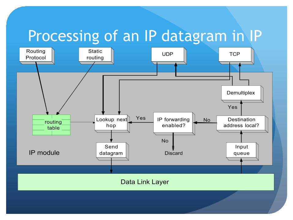
Processing of an IP datagram in IP UDP TCP
Inputqueue
Lookup nexthop
RoutingProtocol
Destinationaddress local?
Staticrouting
Yes
Senddatagram
IP forwardingenabled?
No
Discard
Yes No
Demultiplex
routingtable
IP module
Data Link Layer
43
Processing of an IP datagram in IP
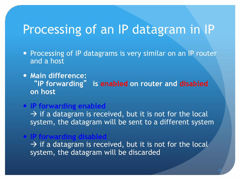
Processing of IP datagrams is very similar on an IP router and a host
Main difference: “IP forwarding” is enabled on router and disabled on host
IP forwarding enabled if a datagram is received, but it is not for the local system, the datagram will be sent to a different system
IP forwarding disabled if a datagram is received, but it is not for the local system, the datagram will be discarded
44
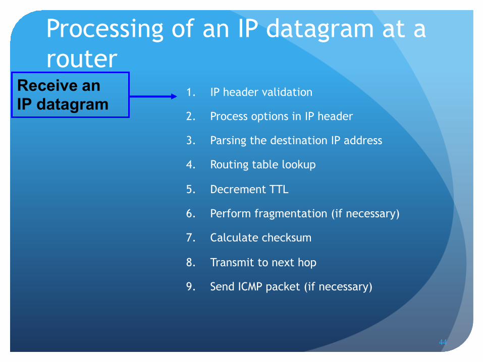
Processing of an IP datagram at a router
1. IP header validation
2. Process options in IP header
3. Parsing the destination IP address
4. Routing table lookup
5. Decrement TTL
6. Perform fragmentation (if necessary)
7. Calculate checksum
8. Transmit to next hop
9. Send ICMP packet (if necessary)
Receive an IP datagram
45
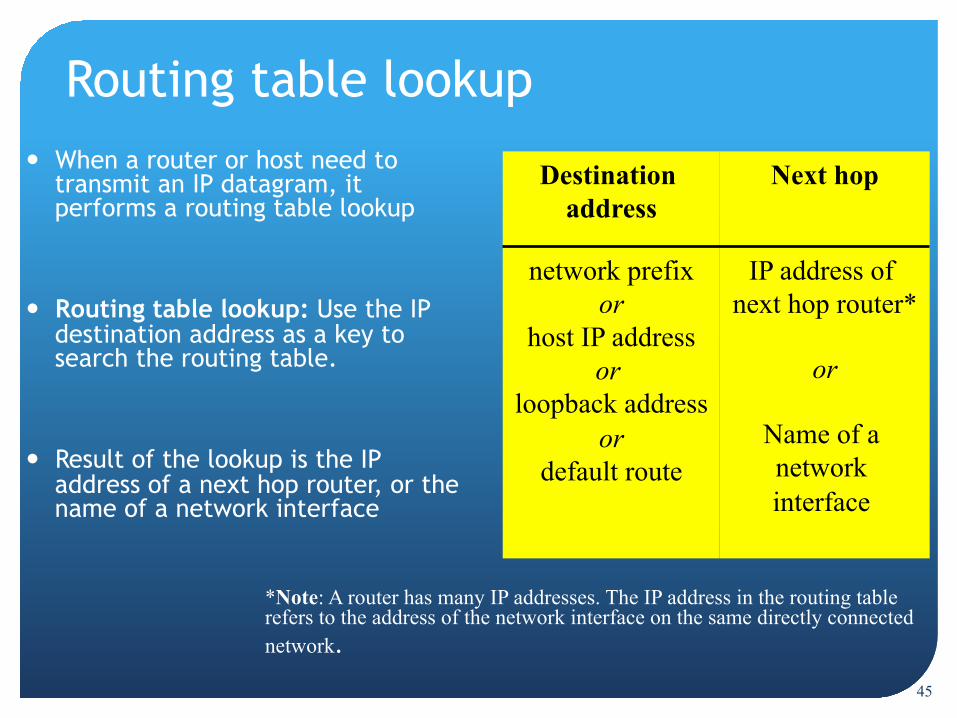
Routing table lookup When a router or host need to
transmit an IP datagram, it performs a routing table lookup
Routing table lookup: Use the IP destination address as a key to search the routing table.
Result of the lookup is the IP address of a next hop router, or the name of a network interface
Destination address Next hop
network prefix or
host IP address or
loopback address or
default route
IP address of next hop router*
or
Name of a network interface
*Note: A router has many IP addresses. The IP address in the routing table refers to the address of the network interface on the same directly connected network.

46
Type of routing table entries Network route
Destination addresses is a network address (e.g., 10.0.2.0/24) Most entries are network routes
Host route Destination address is an interface address (e.g., 10.0.1.2/32) Used to specify a separate route for certain hosts
Default route Used when no network or host route matches The router that is listed as the next hop of the default route is
the default gateway (for Cisco: “gateway of last resort)
Loopback address Routing table for the loopback address (127.0.0.1) The next hop lists the loopback (lo0) interface as outgoing
interface
47
Destination address Next hop
10.0.0.0/8 128.143.0.0/16 128.143.64.0/20
128.143.192.0/20 128.143.71.0/24
128.143.71.55/32 default
R1 R2 R3 R3 R4 R3 R5
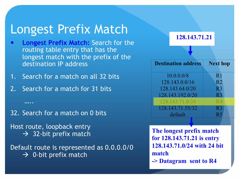
Longest Prefix Match Longest Prefix Match: Search for the
routing table entry that has the longest match with the prefix of the destination IP address
1. Search for a match on all 32 bits
2. Search for a match for 31 bits
…..
32. Search for a match on 0 bits
Host route, loopback entry 32-bit prefix match
Default route is represented as 0.0.0.0/0 0-bit prefix match
128.143.71.21
The longest prefix match for 128.143.71.21 is entry 128.143.71.0/24 with 24 bit match -> Datagram sent to R4

48
Route Aggregation Longest prefix match algorithm permits the aggregation of
prefixes with identical next hop address to a single entry
This contributes significantly to reducing the size of routing tables of Internet routers
Destination Next Hop 10.1.0.0/24 10.1.2.0/24 10.2.1.0/24 10.3.1.0/24 20.0.0.0/14
R3 direct direct
R3 R2
Destination Next Hop 10.1.0.0/24 10.1.2.0/24 10.2.1.0/24 10.3.1.0/24 20.2.0.0/16 20.1.1.0/28
R3 direct direct
R3 R2 R2
49
Destination Next Hop 10.1.0.0/24 …
R2
Destination Next Hop 10.1.0.0/24 …
R1
Ethernet
H1
R1 R2
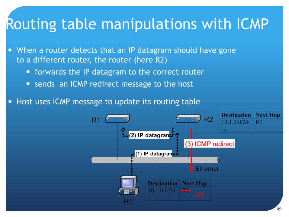
Routing table manipulations with ICMP
When a router detects that an IP datagram should have gone to a different router, the router (here R2)
forwards the IP datagram to the correct router sends an ICMP redirect message to the host
Host uses ICMP message to update its routing table
(1) IP datagram
R1
(2) IP datagram(3) ICMP redirect
50
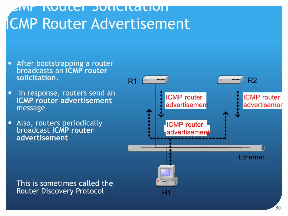
ICMP Router Solicitation ICMP Router Advertisement
After bootstrapping a router broadcasts an ICMP router solicitation.
In response, routers send an ICMP router advertisement message
Also, routers periodically broadcast ICMP router advertisement
This is sometimes called the Router Discovery Protocol
Ethernet
H1
R1 R2
ICMP routeradvertisement
ICMP routeradvertisement
ICMP routeradvertisement