IP Protection
6
Altech Corp.® • 35 Royal Road • Flemington, NJ 08822-6000 • Phone (908)806-9400 • FAX (908)806-9490 • www.altechcorp.com 141 Technical Annex CHART I International Protection (IP) Ratings to IEC 529 CHART II NEMA / IP Cross Reference The chart below provides a cross-reference from NEMA to International Protection (IP) Ratings. This cross-reference is an approximation based on the most current information available. It is not sanctioned by NEMA, IEC, or any other regulatory body. This chart should be used only as a guideline. IEC 529 NEMA Ratings Protection Ratings 1 2 3 3R 4 4X 5 6 12 13 IP 00 IP 10 IP 11 IP 20 IP 21 IP 22 IP 23 IP 30 IP 31 IP 32 IP 33 IP 40 IP 41 IP 42 IP 43 IP 50 IP 51 IP 52 IP 53 IP 54 IP 55 IP 56 IP 60 IP 61 IP 62 IP 63 IP 64 IP 65 IP 66 IP 67 IP 68 IP 0X IP 1X IP 2X IP 3X IP 00 IP 10 IP 11 IP 12 IP 20 IP 21 IP 22 IP 23 IP 30 IP 31 IP 32 IP 33 IP 34 IP 40 IP 41 IP 42 IP 43 IP 44 IP 50 IP 54 IP 55 IP 60 IP 65 IP 66 IP 67 IP 68 IP 4X IP 5X IP 6X IP X0 IP X1 IP X2 IP X3 IP X4 IP X5 IP X6 IP X7 IP X8 No Protection Protection Protection Protection Protection Protection Protection Protection Protection against against against against against against against against dripping dripping dripping splashing water jets heavy seas effects submersion water water even water even water from from any from any of falling when tilted when tilted any direction direction immersion vertically 15° 60° direction vertically No protection No protection Protection against Protection against touching with large solid the hand bodies > 50mm Ø Protection against Protect. against touching with med., solid bod- the finger ies > 12.5 mm Ø Protection against Protection touching with tools, against small, wires, etc., solid bodies > 2.5 mm Ø > 2.5 mm Ø First Digit Second Digit – Degree of Water Protection Protection against Protection touching with tools, against small, wires, etc., solid bodies > 1 mm Ø > 1 mm Ø Protection against Protection touching with tools, against internal wires, etc., dust > 1 mm Ø accumulation Protection against Protection touching with tools, against all wires, etc., dust > 1 mm Ø penetration Protection Modes to EN 60529 DIN VDE 0470 Part 1 Protection against penetra- Person tion of foreign touching bodies In some countries a third digit is added. It gives information about the mechanical properties of the equipment. This designation has not yet been standardized according to current DIN and IEC regulations. Devices in this catalogue correspond to digit IP .7.
Transcript of IP Protection
Altech Corp.® • 35 Royal Road • Flemington, NJ 08822-6000 • Phone (908)806-9400 • FAX (908)806-9490 • www.altechcorp.com141
Technical Annex
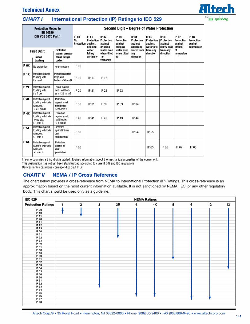
CHART I International Protection (IP) Ratings to IEC 529
CHART II NEMA / IP Cross ReferenceThe chart below provides a cross-reference from NEMA to International Protection (IP) Ratings. This cross-reference is an
approximation based on the most current information available. It is not sanctioned by NEMA, IEC, or any other regulatory
body. This chart should be used only as a guideline.
IEC 529 NEMA Ratings
Protection Ratings 1 2 3 3R 4 4X 5 6 12 13
IP 00IP 10IP 11IP 20IP 21IP 22IP 23IP 30IP 31IP 32IP 33IP 40IP 41IP 42IP 43IP 50IP 51IP 52IP 53IP 54IP 55IP 56IP 60IP 61IP 62IP 63IP 64IP 65IP 66IP 67IP 68
IP 0X
IP 1X
IP 2X
IP 3X
IP 00
IP 10 IP 11 IP 12
IP 20 IP 21 IP 22 IP 23
IP 30 IP 31 IP 32 IP 33 IP 34
IP 40 IP 41 IP 42 IP 43 IP 44
IP 50 IP 54 IP 55
IP 60 IP 65 IP 66 IP 67 IP 68
IP 4X
IP 5X
IP 6X
IP X0 IP X1 IP X2 IP X3 IP X4 IP X5 IP X6 IP X7 IP X8 No Protection Protection Protection Protection Protection Protection Protection Protection Protection against against against against against against against against dripping dripping dripping splashing water jets heavy seas effects submersion water water even water even water from from any from any of falling when tilted when tilted any direction direction immersion vertically 15° 60° direction vertically
No protection No protection
Protection against Protection againsttouching with large solidthe hand bodies > 50mm Ø
Protection against Protect. againsttouching with med., solid bod-the finger ies > 12.5 mm Ø
Protection against Protection touching with tools, against small,wires, etc., solid bodies> 2.5 mm Ø > 2.5 mm Ø
First Digit
Second Digit – Degree of Water Protection
Protection against Protection touching with tools, against small,wires, etc., solid bodies > 1 mm Ø > 1 mm Ø
Protection against Protectiontouching with tools, against internalwires, etc., dust> 1 mm Ø accumulation
Protection against Protectiontouching with tools, against allwires, etc., dust> 1 mm Ø penetration
Protection Modes to EN 60529
DIN VDE 0470 Part 1
Protection against penetra- Person tion of foreign touching bodies
In some countries a third digit is added. It gives information about the mechanical properties of the equipment.This designation has not yet been standardized according to current DIN and IEC regulations.Devices in this catalogue correspond to digit IP .7.
Altech Corp.® • 35 Royal Road • Flemington, NJ 08822-6000 • Phone (908)806-9400 • FAX (908)806-9490 • www.altechcorp.com142
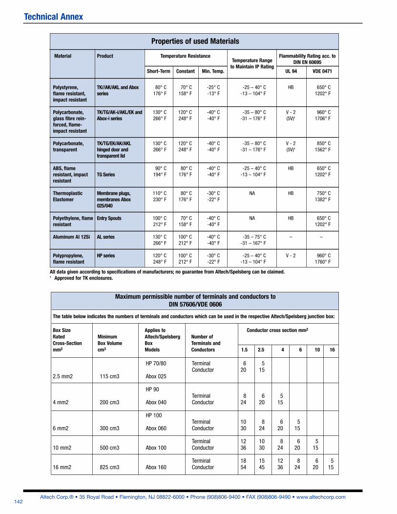
The table below indicates the numbers of terminals and conductors which can be used in the respective Altech/Spelsberg junction box:
Box Size Applies to Conductor cross section mm2
Rated Minimum Altech/Spelsberg Number ofCross-Section Box Volume Box Terminals andmm2 cm3 Models Conductors 1.5 2.5 4 6 10 16
HP 70/80 Terminal 6 5 Conductor 20 152.5 mm2 115 cm3 Abox 025
HP 90 Terminal 8 6 54 mm2 200 cm3 Abox 040 Conductor 24 20 15
HP 100 Terminal 10 8 6 56 mm2 300 cm3 Abox 060 Conductor 30 24 20 15
Terminal 12 10 8 6 510 mm2 500 cm3 Abox 100 Conductor 36 30 24 20 15
Terminal 18 15 12 8 6 516 mm2 825 cm3 Abox 160 Conductor 54 45 36 24 20 15
Maximum permissible number of terminals and conductors toDIN 57606/VDE 0606
Properties of used Materials
TK//AK/AKL and Aboxseries
TK/TG/AK-i/AKL/EK andAbox-i series
TK/TG/EK/AK/AKLhinged door andtransparent lid
TG Series
Membrane plugs,membranes Abox025/040
Entry Spouts
AL series
HP series
All data given according to specifications of manufacturers; no guarantee from Altech/Spelsberg can be claimed.1 Approved for TK enclosures.
Technical Annex
80° C176° F
130° C266° F
130° C266° F
90° C194° F
110° C230° F
100° C212° F
130° C266° F
120° C248° F
70° C158° F
120° C248° F
120° C248° F
80° C176° F
80° C176° F
70° C158° F
100° C212° F
100° C212° F
-25° C-13° F
-40° C-40° F
-40° C-40° F
-40° C-40° F
-30° C-22° F
-40° C-40° F
-40° C-40° F
-30° C-22° F
HB
V - 2(5V)1
V - 2(5V)1
HB
HB
HB
–
V - 2
650° C1202° F
960° C1706° F
850° C1562° F
650° C1202° F
750° C1382° F
650° C1202° F
–
960° C1760° F
Temperature Resistance Flammability Rating acc. toDIN EN 60695
-25 – 40° C-13 – 104° F
-35 – 80° C-31 – 176° F
-35 – 80° C-31 – 176° F
-25 – 40° C-13 – 104° F
NA
NA
-35 – 75° C-31 – 167° F
-25 – 40° C-13 – 104° F
Temperature Rangeto Maintain IP Rating
Polystyrene,flame resistant,impact resistant
Polycarbonate,glass fibre rein-forced, flame-impact resistant
Polycarbonate,transparent
ABS, flameresistant, impactresistant
ThermoplasticElastomer
Polyethylene, flameresistant
Aluminum Al 12Si
Polypropylene,flame resistant
Material Product
Short-Term Constant Min. Temp. UL 94 VDE 0471
Material Product
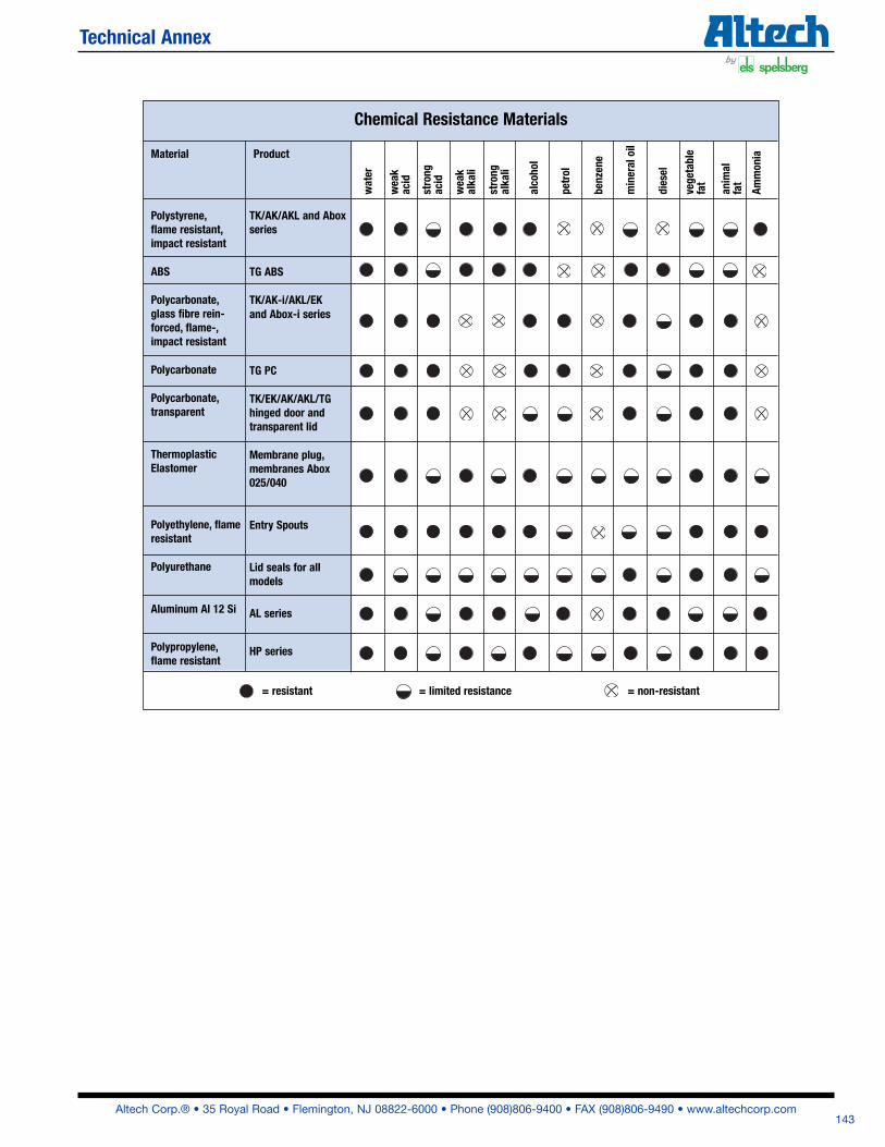
Chemical Resistance Materials
Polystyrene,flame resistant,impact resistant
ABS
Polycarbonate,glass fibre rein-forced, flame-,impact resistant
Polycarbonate
Polycarbonate,transparent
ThermoplasticElastomer
Polyethylene, flameresistant
Polyurethane
Aluminum Al 12 Si
Polypropylene,flame resistant
water
wea
kac
id
strong
acid
wea
kalka
li
strong
alka
li
vege
table
fat
anim
alfat
= resistant = limited resistance = non-resistant
diesel
benz
ene
petrol
alco
hol
mineral oil
Ammon
ia
TK/AK/AKL and Aboxseries
TG ABS
TK/AK-i/AKL/EKand Abox-i series
TG PC
TK/EK/AK/AKL/TGhinged door andtransparent lid
Membrane plug,membranes Abox025/040
Entry Spouts
Lid seals for allmodels
AL series
HP series
Altech Corp.® • 35 Royal Road • Flemington, NJ 08822-6000 • Phone (908)806-9400 • FAX (908)806-9490 • www.altechcorp.com143
Technical Annex
The degree of weather resistance given by the polycarbonate enclosures used is generally adequate. Theenclosures have been tested under practical conditions in tropical regions for many years. If transparent lids areused, it is recommended to protect them against the direct effects of sun radiation. The American UL testing laboratories have approved several types of the PC series. A part of this examination is thetest for UV resistance (UL 746 C). The weather proof test according to DIN 53 387 / 1000 hours was conducted at the "National Materials TestingAuthority" in Dortmund.Materials tested: Polyethylene gray + black Polycarbonate, 15% GV, gray Polypropylene gray Polycarbonate, transparent TPE gray Polycarbonate, smoky topaz FS 131 grayNote: The test reports can be obtained from us free of charge.
UV - Resistance
For installation in air raid shelters in accordance with standard test class RK 0.63/6.3, safety degree A.Devices up to an allowable weight of 2 kg are not subject to compulsory testing. Of the larger enclosures, the following types have been tested and approved:
• TK 2518, TK 3625 as empty enclosure• RK 2518, RK 3625 as serial terminal enclosure • EK 12, EK 24 as distribution box• AK 12, AK 24 as distribution board (Application certificate 023/95)
Approval through «Bureau Veritas»
The following program series have been approved (Nr. 2661/2869/BO/OD) and are consequently suitable forinstallation in ships and shipyards:
• EK- Series distribution boards• Nautic- Series junction boxes • RK- Series terminal boxes• TK- Series empty enclosures
Shock-Testing by the Federal Office for Civil Defense
Polyurethane - sealing material
All enclosure types utilize a seal composed of a dual-component, specialty mixture. The seals are halogen-free,chemically resistant (see summary on pg. 120) and especially temperature resistant. The seals are inserted byrobots, are exactly evenly distributed, and have a solid grip on the upper section of the enclosure. Consequently, asecure and safe respect reliable function of the seals is guaranteed.
Altech Corp.® • 35 Royal Road • Flemington, NJ 08822-6000 • Phone (908)806-9400 • FAX (908)806-9490 • www.altechcorp.com144
Technical Annex
Altech Corp.® • 35 Royal Road • Flemington, NJ 08822-6000 • Phone (908)806-9400 • FAX (908)806-9490 • www.altechcorp.com145
Technical Annex
A B C D
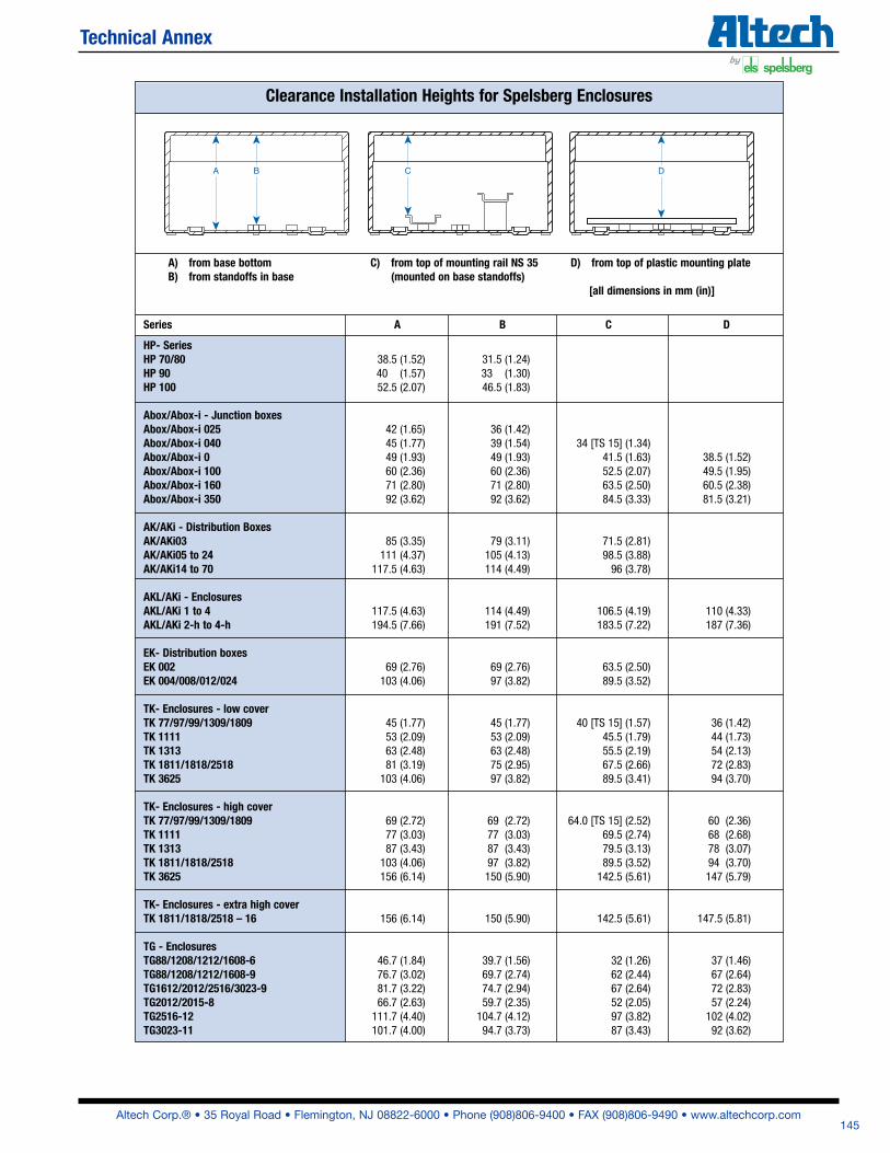
HP- Series HP 70/80 38.5 (1.52) 31.5 (1.24)HP 90 40 (1.57) 33 (1.30)HP 100 52.5 (2.07) 46.5 (1.83)
Abox/Abox-i - Junction boxesAbox/Abox-i 025 42 (1.65) 36 (1.42)Abox/Abox-i 040 45 (1.77) 39 (1.54) 34 [TS 15] (1.34)Abox/Abox-i 0 49 (1.93) 49 (1.93) 41.5 (1.63) 38.5 (1.52)Abox/Abox-i 100 60 (2.36) 60 (2.36) 52.5 (2.07) 49.5 (1.95)Abox/Abox-i 160 71 (2.80) 71 (2.80) 63.5 (2.50) 60.5 (2.38)Abox/Abox-i 350 92 (3.62) 92 (3.62) 84.5 (3.33) 81.5 (3.21)
AK/AKi - Distribution BoxesAK/AKi03 85 (3.35) 79 (3.11) 71.5 (2.81)AK/AKi05 to 24 111 (4.37) 105 (4.13) 98.5 (3.88)AK/AKi14 to 70 117.5 (4.63) 114 (4.49) 96 (3.78)
AKL/AKi - EnclosuresAKL/AKi 1 to 4 117.5 (4.63) 114 (4.49) 106.5 (4.19) 110 (4.33)AKL/AKi 2-h to 4-h 194.5 (7.66) 191 (7.52) 183.5 (7.22) 187 (7.36)
EK- Distribution boxesEK 002 69 (2.76) 69 (2.76) 63.5 (2.50)EK 004/008/012/024 103 (4.06) 97 (3.82) 89.5 (3.52)
TK- Enclosures - low coverTK 77/97/99/1309/1809 45 (1.77) 45 (1.77) 40 [TS 15] (1.57) 36 (1.42)TK 1111 53 (2.09) 53 (2.09) 45.5 (1.79) 44 (1.73)TK 1313 63 (2.48) 63 (2.48) 55.5 (2.19) 54 (2.13)TK 1811/1818/2518 81 (3.19) 75 (2.95) 67.5 (2.66) 72 (2.83)TK 3625 103 (4.06) 97 (3.82) 89.5 (3.41) 94 (3.70)
TK- Enclosures - high coverTK 77/97/99/1309/1809 69 (2.72) 69 (2.72) 64.0 [TS 15] (2.52) 60 (2.36)TK 1111 77 (3.03) 77 (3.03) 69.5 (2.74) 68 (2.68)TK 1313 87 (3.43) 87 (3.43) 79.5 (3.13) 78 (3.07)TK 1811/1818/2518 103 (4.06) 97 (3.82) 89.5 (3.52) 94 (3.70)TK 3625 156 (6.14) 150 (5.90) 142.5 (5.61) 147 (5.79)
TK- Enclosures - extra high coverTK 1811/1818/2518 – 16 156 (6.14) 150 (5.90) 142.5 (5.61) 147.5 (5.81)
TG - EnclosuresTG88/1208/1212/1608-6 46.7 (1.84) 39.7 (1.56) 32 (1.26) 37 (1.46)TG88/1208/1212/1608-9 76.7 (3.02) 69.7 (2.74) 62 (2.44) 67 (2.64)TG1612/2012/2516/3023-9 81.7 (3.22) 74.7 (2.94) 67 (2.64) 72 (2.83)TG2012/2015-8 66.7 (2.63) 59.7 (2.35) 52 (2.05) 57 (2.24)TG2516-12 111.7 (4.40) 104.7 (4.12) 97 (3.82) 102 (4.02)TG3023-11 101.7 (4.00) 94.7 (3.73) 87 (3.43) 92 (3.62)
Clearance Installation Heights for Spelsberg Enclosures
A) from base bottom B) from standoffs in base
C) from top of mounting rail NS 35 (mounted on base standoffs)
D) from top of plastic mounting plate
[all dimensions in mm (in)]
Series A B C D
Altech Corp.® • 35 Royal Road • Flemington, NJ 08822-6000 • Phone (908)806-9400 • FAX (908)806-9490 • www.altechcorp.com146
Technical Annex
1
51
1
1 5
1
4
1
1
1
1
51
1
1
11 11 11
331
1
1
1
1
1
1
1 1
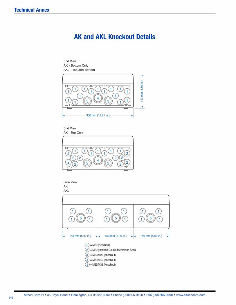
150 mm (5.90 in.) 150 mm (5.90 in.) 150 mm (5.90 in.)
300 mm (11.81 in.)
142
mm
(5.5
9 in
.)
4
11 11 12
222
2
2
1
2
1
2
2 2
1 = M20 (Knockout)
2 = M20 (Installed Double Membrane Seal)
3 = M20/M25 (Knockout)
4 = M32/M40 (Knockout)
= M25/M32 (Knockout)
End ViewAK – Top Only
End ViewAK / AKL
Side ViewAkII / AKL
2 2
5
AK and AKL Knockout Details
End View
AK - Bottom Only
AKL - Top and Bottom
End View
AK - Top Only
Side View
AK
AKL