
IP Communicator Series Product Installation Document
19
IP Communicator Series Product Installation Document PN 53109:I2 7/26/2011 11-494 1 IPDACT - Internet Protocol Digital Alarm Communicator/ Transmitter The IPDACT, IPDACT-2 and IPDACT-2UD are compact, Internet Protocol Digital Alarm Communicators/Transmitters designed to allow FACP status communication to a Central Station via the internet. Using Contact ID protocol from the FACP, the IPDACT Series convert the standard DACT phone communication to a protocol that can be transmitted and received via the internet. They also check connectivity between the FACP and Central Station. The IPDACT Series operate in conjunction with the VisorALARM receiver, located at the Central Station. The Visor ALARM receives signals transmitted by the IPDACT Series over the internet, instead of the traditional public switched telephone lines, and sends the signals through a serial port to automation software for processing. The installer must determine whether the FACP has enough reserve auxiliary power (24 VDC nonresettable, filtered, reg- ulated) to supply the IPDACT Series module. The following table lists the power requirements for each version of the IPDACT. If the FACP cannot supply sufficient auxiliary power, the IPDACT Series module requires an auxiliary power supply such as the HP300ULX as described in Section 2.3. 2 IPDACT Series Mounting/Wiring Options There are several mounting options available for the IPDACT Series. The following sections describe these options. The tables below are a guide for IPDACT Series mounting. The following models are compatible with IPDACT Series Models. IPDACT Model Alarm Current Standby Current IPDACT 129 mA 100 mA IPDACT-2 136 mA 93 mA IPDACT-2UD 155 mA 98 mA NOTES: 1. Following installation, refer to the Quick Startup Guide, supplied with the IPDACT, for programming and activation of the IPDACT Series on the internet. 2. Although not required, the FACP Secondary Phone Line may be connected to the Public Switched Telephone Network (i.e. a POTS line) for backup reporting. 3. Installation and wiring of this device must be done in accordance with NFPA 70, 72 and local ordinances. 4. The IPDACT can only be used for commercial fire applications. Application (Power Source) Mounting Location Refer to Mounting Instruction Section No Reserve Auxiliary Power HP300ULX Enclosure Section 2.3 on page 12 MS-9600(UD)LS FACP Enclosure Section 2.1.1 on page 4 MS-9200UD(E) IPENC Enclosure Section 2.2 on page 10 MS-9200UDLS(E) FACP Enclosure Section 2.1.1 on page 4 MS-9050UD FACP Enclosure Section 2.1.1 on page 4 MS-5UD-3(C)(E) 1 FACP Enclosure Section 2.1.1 on page 4 MS-10UD-7(C)(E) 1 FACP Enclosure Section 2.1.1 on page 4 MS-25 2 HP300ULX Enclosure Section 2.3 on page 12 Table 1 IPDACT Series Mounting/Wiring Options
Transcript of IP Communicator Series Product Installation Document

IP Communicator SeriesProduct Installation Document
PN 53109:I2 7/26/2011 11-494
1 IPDACT - Internet Protocol Digital Alarm Communicator/TransmitterThe IPDACT, IPDACT-2 and IPDACT-2UD are compact, Internet Protocol Digital Alarm Communicators/Transmitters designed to allow FACP status communication to a Central Station via the internet. Using Contact ID protocol from the FACP, the IPDACT Series convert the standard DACT phone communication to a protocol that can be transmitted and received via the internet. They also check connectivity between the FACP and Central Station.
The IPDACT Series operate in conjunction with the VisorALARM receiver, located at the Central Station. The Visor ALARM receives signals transmitted by the IPDACT Series over the internet, instead of the traditional public switched telephone lines, and sends the signals through a serial port to automation software for processing.
The installer must determine whether the FACP has enough reserve auxiliary power (24 VDC nonresettable, filtered, reg-ulated) to supply the IPDACT Series module. The following table lists the power requirements for each version of the IPDACT.
If the FACP cannot supply sufficient auxiliary power, the IPDACT Series module requires an auxiliary power supply such as the HP300ULX as described in Section 2.3.
2 IPDACT Series Mounting/Wiring OptionsThere are several mounting options available for the IPDACT Series. The following sections describe these options. The tables below are a guide for IPDACT Series mounting.
The following models are compatible with IPDACT Series Models.
IPDACT Model Alarm Current Standby Current
IPDACT 129 mA 100 mA
IPDACT-2 136 mA 93 mA
IPDACT-2UD 155 mA 98 mA
NOTES:1. Following installation, refer to the Quick Startup Guide, supplied with the IPDACT, for programming and activation of the IPDACT Series on the internet. 2. Although not required, the FACP Secondary Phone Line may be connected to the Public Switched Telephone Network (i.e. a POTS line) for backup reporting.3. Installation and wiring of this device must be done in accordance with NFPA 70, 72 and local ordinances.4. The IPDACT can only be used for commercial fire applications.
Application (Power Source) Mounting Location Refer to Mounting Instruction Section
No Reserve Auxiliary Power HP300ULX Enclosure Section 2.3 on page 12
MS-9600(UD)LS FACP Enclosure Section 2.1.1 on page 4
MS-9200UD(E) IPENC Enclosure Section 2.2 on page 10
MS-9200UDLS(E) FACP Enclosure Section 2.1.1 on page 4
MS-9050UD FACP Enclosure Section 2.1.1 on page 4
MS-5UD-3(C)(E) 1 FACP Enclosure Section 2.1.1 on page 4
MS-10UD-7(C)(E) 1 FACP Enclosure Section 2.1.1 on page 4
MS-25 2 HP300ULX Enclosure Section 2.3 on page 12
Table 1 IPDACT Series Mounting/Wiring Options

2 IP Communicator Series Installation Document — P/N 53109:I2 7/26/2011
MS-25 2 IPENC Enclosure Section 2.2 on page 10
FireWarden-100-2(E) FACP Enclosure Section 2.1.1 on page 4
FireWarden-100(E) IPENC Enclosure Section 2.2 on page 10
FireWarden-50 FACP Enclosure Section 2.1.1 on page 4
SFP-5UD(E)(R) 1 FACP Enclosure Section 2.1.1 on page 4
SFP-10UD(E)(R) 1 FACP Enclosure Section 2.1.1 on page 4
411(UD) 3 HP300ULX Enclosure Section 2.4 on page 16
411UDAC 3 HP300ULX Enclosure Section 2.3 on page 12
NFS2-3030(E) 4 FACP Enclosure (IPCHSKIT) 5 Section 2.1.2 on page 6
NFS2-640(E) 4 FACP Enclosure (IPCHSKIT) 5 Section 2.1.2 on page 6
NFS-320(E)(C) 4 IPENC Enclosure Section 2.2 on page 10
NSP-25 2 HP300ULX Enclosure Section 2.3 on page 12
NSP-25 2 IPENC Enclosure Section 2.2 on page 10
NCA-2 4 FACP Enclosure (IPCHSKIT) 5 Section 2.1.2 on page 6
XLS3000 4 FACP Enclosure (IPCHSKIT) 5 Section 2.1.2 on page 6
XLS140-2 4 FACP Enclosure (IPCHSKIT) 5 Section 2.1.2 on page 6
XLS-NCA2 4 FACP Enclosure (IPCHSKIT) 5 Section 2.1.2 on page 6
IFC2-3030(E) 4 FACP Enclosure (IPCHSKIT) 5 Section 2.1.2 on page 6
IFC2-640(E) 4 FACP Enclosure (IPCHSKIT) 5 Section 2.1.2 on page 6
IFC-320(E)(C) 4 IPENC Enclosure Section 2.2 on page 10
JNCA-2 4 FACP Enclosure (IPCHSKIT) 5 Section 2.1.2 on page 6
Unimode 200 Plus IPENC Enclosure Section 2.2 on page 10
Unimode 9050UD FACP Enclosure Section 2.1.1 on page 4
Unimode 5UD 1 FACP Enclosure Section 2.1.1 on page 4
Unimode 10UD 1 FACP Enclosure Section 2.1.1 on page 4
Unimode 640-2 4 FACP Enclosure (IPCHSKIT) 5 Section 2.1.2 on page 6
ADT-NCA-2 4 FACP Enclosure (IPCHSKIT) 5 Section 2.1.2 on page 6
IQ-636X-2(E) 4 FACP Enclosure (IPCHSKIT) 5 Section 2.1.2 on page 6
IQ-318(E)(C) 4 IPENC Enclosure Section 2.2 on page 10
AP-NCA-2 4 FACP Enclosure (IPCHSKIT) 5 Section 2.1.2 on page 6
MICRO-320I(E) 4 IPENC Enclosure Section 2.2 on page 10
E3 Series 6 IPENC Enclosure Section 2.2 on page 10
GF505(W) 1 FACP Enclosure Section 2.1.1 on page 4
GF510(W) 1 FACP Enclosure Section 2.1.1 on page 4
GIF100 2 HP300ULX Enclosure Section 2.3 on page 12
GIF100 2 IPENC Enclosure Section 2.2 on page 10
5820XL 7 HP300ULX Enclosure Section 2.3 on page 12
5820XL 7 IPENC Enclosure Section 2.2 on page 10
5808 7 HP300ULX Enclosure Section 2.3 on page 12
5808 7 IPENC Enclosure Section 2.2 on page 10
IFP-2000 / IFP-2000VIP 7 HP300ULX Enclosure Section 2.3 on page 12
IFP-2000 / IFP-2000VIP 7 IPENC Enclosure Section 2.2 on page 10
IFP-1000 / IFP-1000VIP 7 HP300ULX Enclosure Section 2.3 on page 12
IFP-1000 / IFP-1000VIP 7 IPENC Enclosure Section 2.2 on page 10
IFP-100 / IFP-100VIP 7 HP300ULX Enclosure Section 2.3 on page 12
IFP-100 / IFP-100VIP 7 IPENC Enclosure Section 2.2 on page 10
IFP-50 / IFP-50VIP 2 HP300ULX Enclosure Section 2.3 on page 12
Application (Power Source) Mounting Location Refer to Mounting Instruction Section
Table 1 IPDACT Series Mounting/Wiring Options

IP Communicator Series Installation Document — P/N 53109:I2 7/26/2011 3
The following models are to be used with the IPDACT Series for retrofit applications only.
IFP-50 / IFP-50VIP 2 IPENC Enclosure Section 2.2 on page 10
5700 2 HP300ULX Enclosure Section 2.3 on page 12
5700 2 IPENC Enclosure Section 2.2 on page 10
5600 2 HP300ULX Enclosure Section 2.3 on page 12
5600 2 IPENC Enclosure Section 2.2 on page 10
5208 2 HP300ULX Enclosure Section 2.3 on page 12
5208 2 IPENC Enclosure Section 2.2 on page 10
5104 2, 8 HP300ULX Enclosure Section 2.3 on page 12
5104 2, 8 IPENC Enclosure Section 2.2 on page 10
IFP-25 2 HP300ULX Enclosure Section 2.3 on page 12
IFP-25 2 IPENC Enclosure Section 2.2 on page 10
1 The IPDACT is powered by the HP300ULX Power Supply only (not required for the IPDACT-2 and IPDACT-2UD)
2 This panel is compatible with the IPDACT-2 model only.3 Provides a complete communicator solution for any fire monitoring application.4 Use of the UDACT Universal Digital Alarm Communicator/Transmitter is required for this
application. (For more information, see the UDACT Manual #50050.) This panel is only compatible with the IPDACT-2 model.
5 If the system configuration does not support installation of the IPCHSKIT, use the IPENC enclosure.6 Use of the DACT-E3 Digital Alarm Communicator/Transmitter is required for this application. (For
more information, see the DACT-E3 Installation Document #9000-0581.) This panel is only compatible with the IPDACT-2 model.
7 This panel is compatible with the IPDACT-2 and IPDACT-2UD only.8 This panel must be used with the HP300ULX Power Supply.
Application (Power Source) Mounting Location Refer to Mounting Instruction Section
MS-9600 IPENC Enclosure Section 2.2 on page 10
Unimode 9600 IPENC Enclosure Section 2.2 on page 10
MS-5024UD IPENC Enclosure Section 2.2 on page 10
MS-5210UD IPENC Enclosure Section 2.2 on page 10
SFP-1024 IPENC Enclosure Section 2.2 on page 10
Unimode 5 IPENC Enclosure Section 2.2 on page 10
Unimode 10 IPENC Enclosure Section 2.2 on page 10
NFS-3030(E) 1 FACP Enclosure (IPCHSKIT) 2 Section 2.1.2 on page 6
NFS-640(E) 1 FACP Enclosure (IPCHSKIT) 2 Section 2.1.2 on page 6
NCA 1 FACP Enclosure (IPCHSKIT) 2 Section 2.1.2 on page 6
AM2020/AFP-1010 1 FACP Enclosure (IPCHSKIT) 2 Section 2.1.2 on page 6
System 5000(C) 1 FACP Enclosure (IPCHSKIT) 2 Section 2.1.2 on page 6
System 500(C) 1 FACP Enclosure (IPCHSKIT) 2 Section 2.1.2 on page 6
AFP-300/400 1 FACP Enclosure (IPCHSKIT) 2 Section 2.1.2 on page 6
AFP-200(C) 1 IPENC Enclosure Section 2.2 on page 10
AFP-100(E) 1 IPENC Enclosure Section 2.2 on page 10
XLS140 1 FACP Enclosure (IPCHSKIT) 2 Section 2.1.2 on page 6
XLS-NCA 1 FACP Enclosure (IPCHSKIT) 2 Section 2.1.2 on page 6
IFC-640(E) 1 FACP Enclosure (IPCHSKIT) 2 Section 2.1.2 on page 6
JNCA 1 FACP Enclosure (IPCHSKIT) 2 Section 2.1.2 on page 6
IFC-2020/1010 1 FACP Enclosure (IPCHSKIT) 2 Section 2.1.2 on page 6
Table 2 IPDACT Series Mounting/Wiring Options for Retrofit Applications
Application (Power Source) Mounting Location Refer to Mounting Instruction Section
Table 1 IPDACT Series Mounting/Wiring Options
4 IP Communicator Series Installation Document — P/N 53109:I2 7/26/2011
2.1 Mounting IPDACT Series in the Fire Alarm Control Panel EnclosureInstall the IPDACT Series in the FACP backbox using the IPBRKT bracket or the IPCHSKIT, as described below.
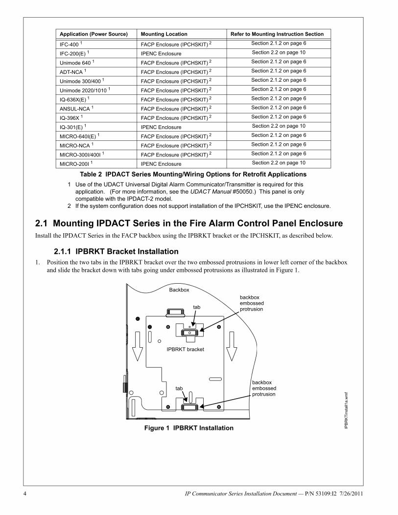
2.1.1 IPBRKT Bracket Installation1. Position the two tabs in the IPBRKT bracket over the two embossed protrusions in lower left corner of the backbox
and slide the bracket down with tabs going under embossed protrusions as illustrated in Figure 1.
IFC-400 1 FACP Enclosure (IPCHSKIT) 2 Section 2.1.2 on page 6
IFC-200(E) 1 IPENC Enclosure Section 2.2 on page 10
Unimode 640 1 FACP Enclosure (IPCHSKIT) 2 Section 2.1.2 on page 6
ADT-NCA 1 FACP Enclosure (IPCHSKIT) 2 Section 2.1.2 on page 6
Unimode 300/400 1 FACP Enclosure (IPCHSKIT) 2 Section 2.1.2 on page 6
Unimode 2020/1010 1 FACP Enclosure (IPCHSKIT) 2 Section 2.1.2 on page 6
IQ-636X(E) 1 FACP Enclosure (IPCHSKIT) 2 Section 2.1.2 on page 6
ANSUL-NCA 1 FACP Enclosure (IPCHSKIT) 2 Section 2.1.2 on page 6
IQ-396X 1 FACP Enclosure (IPCHSKIT) 2 Section 2.1.2 on page 6
IQ-301(E) 1 IPENC Enclosure Section 2.2 on page 10
MICRO-640I(E) 1 FACP Enclosure (IPCHSKIT) 2 Section 2.1.2 on page 6
MICRO-NCA 1 FACP Enclosure (IPCHSKIT) 2 Section 2.1.2 on page 6
MICRO-300I/400I 1 FACP Enclosure (IPCHSKIT) 2 Section 2.1.2 on page 6
MICRO-200I 1 IPENC Enclosure Section 2.2 on page 10
1 Use of the UDACT Universal Digital Alarm Communicator/Transmitter is required for this application. (For more information, see the UDACT Manual #50050.) This panel is only compatible with the IPDACT-2 model.
2 If the system configuration does not support installation of the IPCHSKIT, use the IPENC enclosure.
Application (Power Source) Mounting Location Refer to Mounting Instruction Section
Table 2 IPDACT Series Mounting/Wiring Options for Retrofit Applications
Figure 1 IPBRKT Installation
Backbox
tab
backbox embossed protrusion
IPBRKT bracket
tabbackbox embossed protrusion
IPB
RK
Tin
stal
l1a
.wm
f
IP Communicator Series Installation Document — P/N 53109:I2 7/26/2011 5
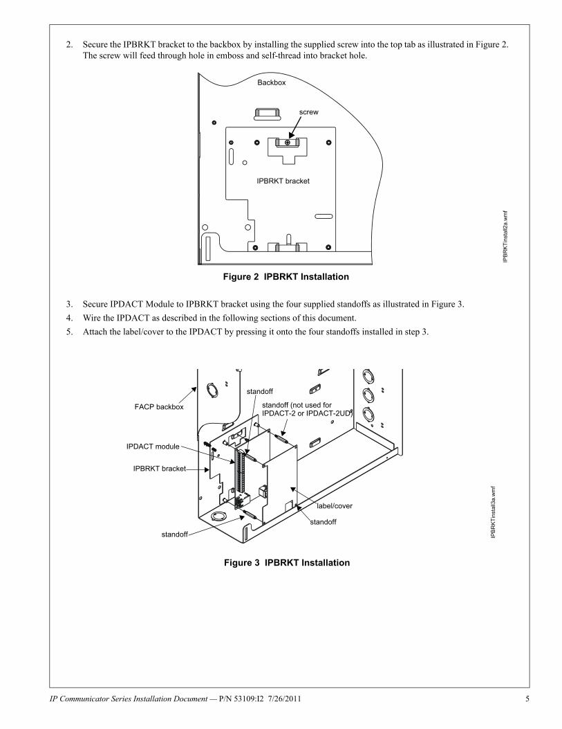
2. Secure the IPBRKT bracket to the backbox by installing the supplied screw into the top tab as illustrated in Figure 2. The screw will feed through hole in emboss and self-thread into bracket hole.
3. Secure IPDACT Module to IPBRKT bracket using the four supplied standoffs as illustrated in Figure 3.
4. Wire the IPDACT as described in the following sections of this document.
5. Attach the label/cover to the IPDACT by pressing it onto the four standoffs installed in step 3.
IPBRKT bracket
Backbox
screw
Figure 2 IPBRKT Installation
IPB
RK
Tin
sta
ll2a.
wm
f
FACP backbox
label/cover
IPBRKT bracket
IPDACT module
standoff
standoff
standoff
standoff (not used for IPDACT-2 or IPDACT-2UD)
Figure 3 IPBRKT Installation
IPB
RK
Tin
stal
l3a
.wm
f
6 IP Communicator Series Installation Document — P/N 53109:I2 7/26/2011
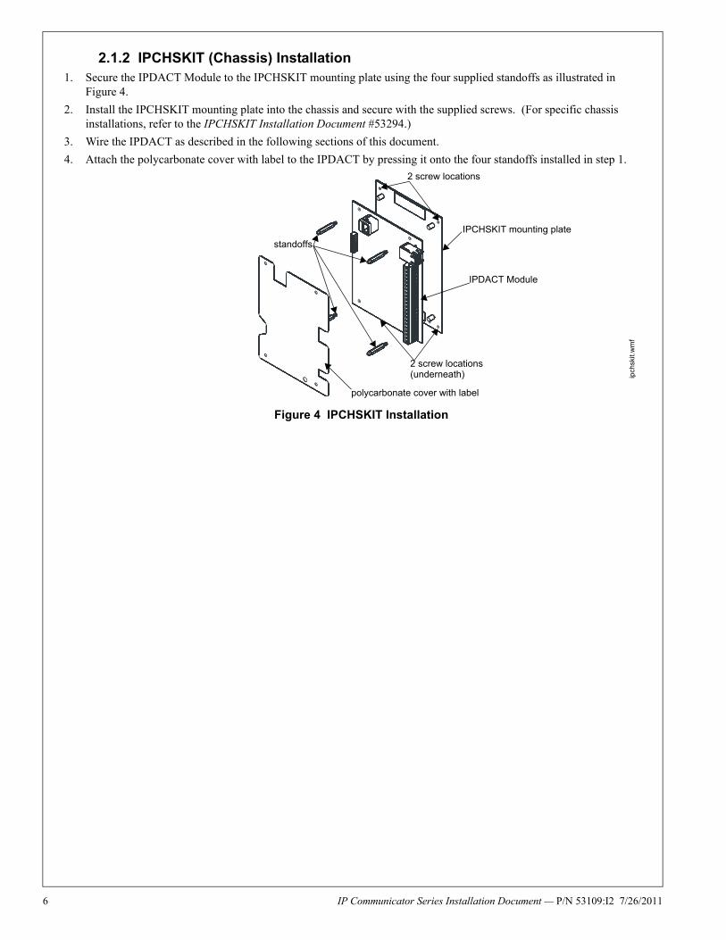
2.1.2 IPCHSKIT (Chassis) Installation1. Secure the IPDACT Module to the IPCHSKIT mounting plate using the four supplied standoffs as illustrated in
Figure 4.
2. Install the IPCHSKIT mounting plate into the chassis and secure with the supplied screws. (For specific chassis installations, refer to the IPCHSKIT Installation Document #53294.)
3. Wire the IPDACT as described in the following sections of this document.
4. Attach the polycarbonate cover with label to the IPDACT by pressing it onto the four standoffs installed in step 1.
IPCHSKIT mounting plate
IPDACT Module
polycarbonate cover with label
standoffs
2 screw locations
2 screw locations(underneath)
Figure 4 IPCHSKIT Installation
ipch
skit.
wm
f
IP Communicator Series Installation Document — P/N 53109:I2 7/26/2011 7
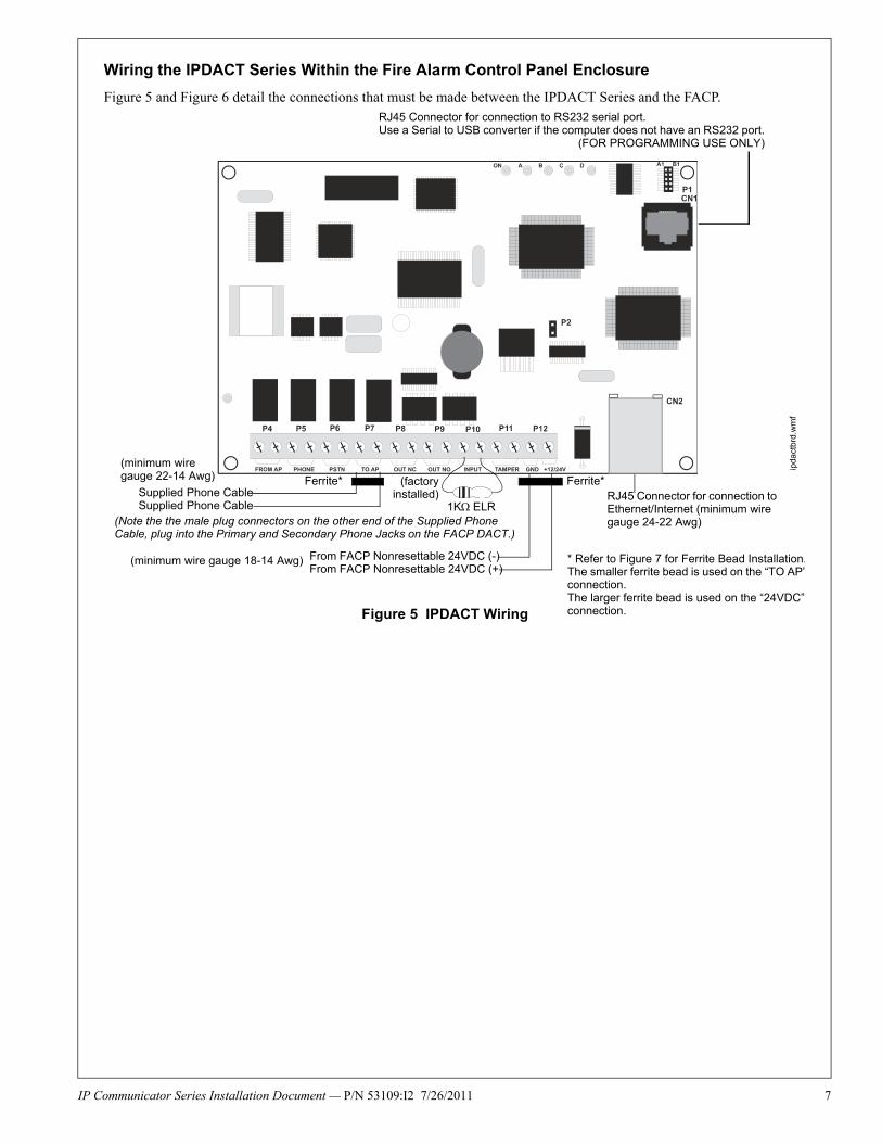
Wiring the IPDACT Series Within the Fire Alarm Control Panel Enclosure
Figure 5 and Figure 6 detail the connections that must be made between the IPDACT Series and the FACP.RJ45 Connector for connection to RS232 serial port.Use a Serial to USB converter if the computer does not have an RS232 port.
(FOR PROGRAMMING USE ONLY)
Supplied Phone CableSupplied Phone Cable
(factoryinstalled)
Ferrite* Ferrite*
(minimum wire gauge 22-14 Awg)
(Note the the male plug connectors on the other end of the Supplied Phone Cable, plug into the Primary and Secondary Phone Jacks on the FACP DACT.)
1KELR
From FACP Nonresettable 24VDC (-) From FACP Nonresettable 24VDC (+)
(minimum wire gauge 18-14 Awg)
RJ45 Connector for connection to Ethernet/Internet (minimum wire gauge 24-22 Awg)
* Refer to Figure 7 for Ferrite Bead Installation.The smaller ferrite bead is used on the “TO AP”connection.The larger ferrite bead is used on the “24VDC” connection.Figure 5 IPDACT Wiring
ipda
ctbr
d.w
mf

8 IP Communicator Series Installation Document — P/N 53109:I2 7/26/2011
Ferrite Bead Installation
A Ferrite Bead is required for the TO AP (smaller bead) to FACP Telco Line wires and for the IPDACT Series 24 VDC (larger bead) Power Supply wires. Each wire must be wrapped twice around the Ferrite Bead at the end closest to IPDACT Series board.
Note that the following illustration depicts one wire wrapped around the Ferrite Bead. The two wires to the TO AP termi-nals must be wrapped around one, smaller Ferrite Bead and the -24 VDC and + 24 VDC wires must be wrapped around a second, larger Ferrite Bead.
RJ45 Connector for connection to RS232 serial port.Use a Serial to USB converter if the computer does not have an RS232 port.
(FOR PROGRAMMING USE ONLY)
2UD Modem Card
Supplied Phone CableSupplied Phone Cable
Ferrite*
(minimum wire gauge 22-14 Awg)
(Note the the male plug connectors on the other end of the Supplied Phone Cable, plug into the Primary and Secondary Phone Jacks on the FACP DACT.)
1KELRs(factory installed)
From FACP Nonresettable 24VDC (-) From FACP Nonresettable 24VDC (+)
RJ45 Connector for connection to Ethernet/Internet (minimum wire gauge 24-22 Awg)
Ferrite*
(minimum wire gauge 18-14 Awg)
Figure 6 IPDACT-2 and IPDACT-2UD Wiring
* Refer to Figure 7 for Ferrite Bead InstallationThe smaller ferrite bead is used on the “TO APconnection.The larger ferrite bead is used on the “24VDC”connection.
ipd
act
-2b
rd_2
UD
.wm
f
Figure 7 Ferrite Bead Installation
ferr
iteip
dact
.wm
f
IP Communicator Series Installation Document — P/N 53109:I2 7/26/2011 9
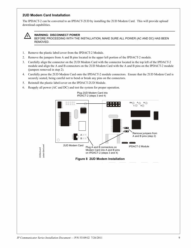
2UD Modem Card Installation
The IPDACT-2 can be converted to an IPDACT-2UD by installing the 2UD Modem Card. This will provide upload/download capabilities.
1. Remove the plastic label/cover from the IPDACT-2 Module.
2. Remove the jumpers from A and B pins located in the upper left portion of the IPDACT-2 module.
3. Carefully align the connector on the 2UD Modem Card with the connector located in the top left of the IPDACT-2 module and align the A and B connectors on the 2UD Modem Card with the A and B pins on the IPDACT-2 module (jumpers removed in step 2).
4. Carefully press the 2UD Modem Card onto the IPDACT-2 module connectors. Ensure that the 2UD Modem Card is securely seated, being careful not to bend or break any pins on the connectors.
5. Reinstall the plastic label/cover on the IPDACT-2UD Module.
6. Reapply all power (AC and DC) and test the system for proper operation.
! WARNING: DISCONNECT POWERBEFORE PROCEEDING WITH THE INSTALLATION, MAKE SURE ALL POWER (AC AND DC) HAS BEEN REMOVED.
Plug A and B connectors on Modem Card into A and B pins on IPDACT-2 (steps 3 and 4)
IPDACT-2 Module
Plug 2UD Modem Card into IPDACT-2 (steps 3 and 4)
2UD Modem Card
Remove jumpers from A and B pins (step 2)
Figure 8 2UD Modem Installation
2UD
brd.
wm
f
ipda
ct-2
brd
.wm
f
10 IP Communicator Series Installation Document — P/N 53109:I2 7/26/2011
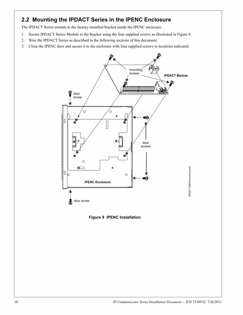
2.2 Mounting the IPDACT Series in the IPENC EnclosureThe IPDACT Series mounts to the factory-installed bracket inside the IPENC enclosure.
1. Secure IPDACT Series Module to the bracket using the four supplied screws as illustrated in Figure 9.
2. Wire the IPDACT Series as described in the following sections of this document.
3. Close the IPENC door and secure it to the enclosure with four supplied screws in locations indicated.
Figure 9 IPENC Installation
mounting screws
door screw
door screw
door screws
IPENC Enclosure
IPDACT Module
IPD
AC
T-E
NC
Fm
oun
t1a
.wm
f
IP Communicator Series Installation Document — P/N 53109:I2 7/26/2011 11
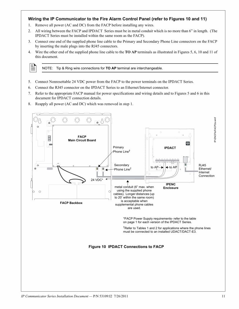
Wiring the IP Communicator to the Fire Alarm Control Panel (refer to Figures 10 and 11)
1. Remove all power (AC and DC) from the FACP before installing any wires.
2. All wiring between the FACP and IPDACT Series must be in metal conduit which is no more than 6” in length. (The IPDACT Series must be installed within the same room as the FACP).
3. Connect one end of the supplied phone line cable to the Primary and Secondary Phone Line connectors on the FACP by inserting the male plugs into the RJ45 connectors.
4. Wire the other end of the supplied phone line cable to the TO AP terminals as illustrated in Figures 5, 6, 10 and 11 of this document.
5. Connect Nonresettable 24 VDC power from the FACP to the power terminals on the IPDACT Series.
6. Connect the RJ45 connector on the IPDACT Series to an Ethernet/Internet connector.
7. Refer to the appropriate FACP manual for power specifications and wiring details and to Figures 5 and 6 in this document for IPDACT connection details.
8. Reapply all power (AC and DC) which was removed in step 1.
NOTE: Tip & Ring wire connections for TO AP terminal are interchangeable.
FACPMain Circuit Board
PrimaryPhone Line†
Secondary
Phone Line†
metal conduit (6” max. when using the supplied phone
cables). Longer distances (up to 20’ within the same room)
is acceptable when supplemental phone cables
are used.
*FACP Power Supply requirements- refer to the table on page 1 for each version of the IPDACT Series.
FACP Backbox
IPDACT
24 VDC*
RJ45 Ethernet/Internet Connection
Figure 10 IPDACT Connections to FACP
to APto AP
†Refer to Tables 1 and 2 for applications where the phone lines must be connected to an installed UDACT/DACT-E3.
IPENCEnclosure
IP-E
NC
Fto
FA
CP
2a.w
mf
12 IP Communicator Series Installation Document — P/N 53109:I2 7/26/2011
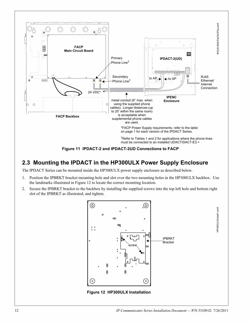
2.3 Mounting the IPDACT in the HP300ULX Power Supply EnclosureThe IPDACT Series can be mounted inside the HP300ULX power supply enclosure as described below.
1. Position the IPBRKT bracket mounting hole and slot over the two mounting holes in the HP300ULX backbox. Use the landmarks illustrated in Figure 12 to locate the correct mounting location.
2. Secure the IPBRKT bracket to the backbox by installing the supplied screws into the top left hole and bottom right slot of the IPBRKT as illustrated, and tighten.
FACPMain Circuit Board
PrimaryPhone Line†
Secondary
Phone Line†
FACP Backbox
IPDACT-2(UD)
24 VDC*
RJ45 Ethernet/Internet Connection
Figure 11 IPDACT-2 and IPDACT-2UD Connections to FACP
to APto AP
*FACP Power Supply requirements- refer to the table on page 1 for each version of the IPDACT Series.
†Refer to Tables 1 and 2 for applications where the phone lines must be connected to an installed UDACT/DACT-E3.=
IPENCEnclosure
IP2
UD
-EN
CF
toF
AC
P2
a.w
mf
metal conduit (6” max. when using the supplied phone
cables). Longer distances (up to 20’ within the same room)
is acceptable when supplemental phone cables
are used.
IPBRKT Bracket
screw
Figure 12 HP300ULX Installation
HP
300U
LXin
sta
ll1.w
mf

IP Communicator Series Installation Document — P/N 53109:I2 7/26/2011 13
3. Attach the four supplied 0.75” M/F standoffs to the IPBRKT as shown in Figure 13.
4. Then, secure the IPDACT Series Module to the IPBRKT using the four supplied M/M standoffs (three for IPDACT-2 and IPDACT-2UD).
5. Wire the IPDACT Series as described in the following sections of this document.
6. Attach the polycarbonate cover with label by pressing it onto the four standoffs installed in step 4.
Wiring the IPDACT Series to the HP300ULX Power Supply and FACPNote: If a 411UD is also installed, refer to for details on wiring both units.
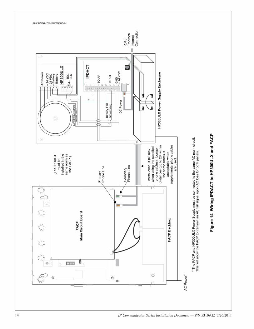
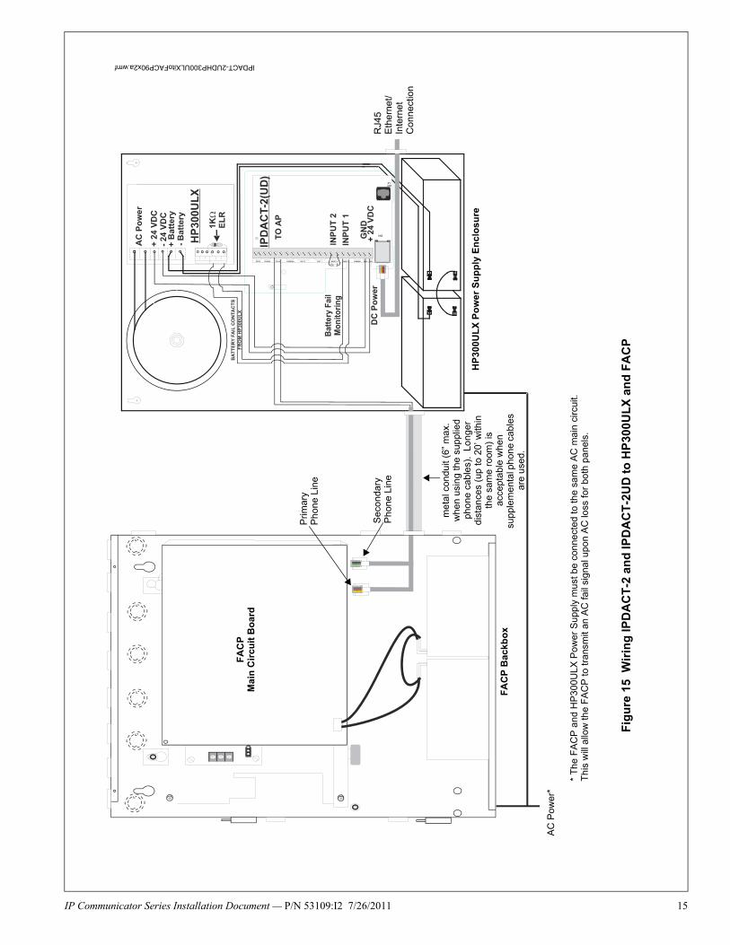
Refer to Figure 14 on page 14 (IPDACT) or Figure 15 on page 15 (IPDACT-2/UD) for an illustration of the following wiring details.
1. Connect the AC power terminals of the FACP and HP300ULX Power Supply to the same AC power main feed. A loss of AC power will cause the FACP to generate an AC Power Loss indication which will be recognized as an AC power loss for both panels.
2. The phone lines between the FACP and IPDACT Series, which is mounted in the HP300ULX backbox, must be in conduit. (The IPDACT Series must be installed in the same room as the FACP).
3. Connect one end of the supplied phone line cable to the Primary and Secondary Phone Line connectors on the FACP by inserting the male plugs into the RJ45 connectors.
4. Wire the other end of the supplied phone line cable to the TO AP terminals of the IPDACT Series as illustrated in Figure 14 (IPDACT) or Figure 15 (IPDACT-2/UD) on the following pages and in Figures 5 or 6 of this document.
5. Connect Nonresettable 24 VDC power from the HP300ULX to the power terminals on the IPDACT Series as illustrated in Figure 14 (IPDACT) or Figure 15 (IPDACT-2/UD).
6. Connect one wire from the Battery Fail NO (Normally Open) contact of the HP300ULX to one of the Input terminals on the IPDACT Series and a second wire from the Battery Fail C (Common) contact of the HP300ULX to the other Input terminal on the IPDACT Series. This will allow the IPDACT Series auxiliary trouble input terminals to monitor for an HP300ULX battery failure.
7. Install a 1K ELR across the Battery Fail NO (Normally Open) contact and the C (Common) contact to allow the IPDACT Series to supervise the wiring.
8. Connect the RJ45 connector on the IPDACT Series to an Ethernet/Internet connector.
9. Refer to the appropriate FACP manual for power specifications and wiring details and to Figures 5 or 6 in this document for IPDACT connection details.
NOTE: Tip & Ring wire connections for TO AP terminal are interchangeable.
M/F standoff (not used for IPDACT-2 or IPDACT-2UD)
standoff (not used for IPDACT-2 or IPDACT-2UD)
standoff
standoff
IPDACT Module
IPBRKT bracket
polycarbonate cover with label
Figure 13 IPDACT Series Mounting in HP300ULX
HP
300
ULX
inst
all3
.wm
f
M/F standoff
M/F standoff
standoff
14 IP Communicator Series Installation Document — P/N 53109:I2 7/26/2011
FA
CP
Mai
n C
ircu
it B
oar
d
FA
CP
Ba
ckb
ox
AC
Pow
er*
HP
300
UL
X P
ow
er S
up
ply
En
clo
sure
RJ4
5 E
ther
net/
Inte
rnet
C
onn
ectio
n
(The
IPD
AC
T
mu
st b
e in
stal
led
in th
e sa
me
room
as
the
FA
CP
.)
Prim
ary
P
hone
Lin
e
Seo
ndar
y
Pho
ne L
ine
* T
he F
AC
P a
nd H
P30
0ULX
Po
wer
Sup
ply
mus
t be
co
nnec
ted
to th
e sa
me
AC
mai
n ci
rcui
t.T
his
will
allo
w th
e F
AC
P to
tran
smit
an A
C fa
il si
gnal
upo
n A
C lo
ss fo
r bo
th p
anel
s.
Fig
ure
14
Wir
ing
IP
DA
CT
to
HP
300
UL
X a
nd
FA
CP
HP300ULXitoFACP90x2a.wmf
met
al c
ondu
it (6
” m
ax.
whe
n u
sing
the
supp
lied
pho
ne c
abl
es).
Lon
ger
dist
ance
s (u
p to
20’
with
in
the
sam
e ro
om)
is
acce
ptab
le w
hen
su
pple
men
tal p
hone
cab
les
are
use
d.
IP Communicator Series Installation Document — P/N 53109:I2 7/26/2011 15
FA
CP
Mai
n C
ircu
it B
oar
d
FA
CP
Bac
kbo
x
AC
Pow
er*
HP
300U
LX
Po
wer
Su
pp
ly E
nc
losu
re
RJ4
5 E
ther
net/
Inte
rnet
C
onne
ctio
n
Prim
ary
P
hone
Lin
e
Sec
onda
ry
Pho
ne L
ine
* T
he F
AC
P a
nd H
P3
00U
LX P
ower
Sup
ply
mus
t be
conn
ecte
d to
the
sam
e A
C m
ain
circ
uit.
Th
is w
ill a
llow
the
FA
CP
to tr
ansm
it an
AC
fail
sign
al u
pon
AC
loss
for
both
pan
els.
Fig
ure
15
W
irin
g IP
DA
CT
-2 a
nd
IPD
AC
T-2
UD
to
HP
300
UL
X a
nd
FA
CP
IPDACT-2UDHP300ULXitoFACP90x2a.wmf
me
tal c
ondu
it (6
” m
ax.
whe
n us
ing
the
supp
lied
phon
e c
able
s).
Lon
ger
dist
ance
s (u
p to
20’
with
in
the
sam
e ro
om)
is
acce
ptab
le w
hen
su
pple
men
tal p
hone
cab
les
are
used
.

16 IP Communicator Series Installation Document — P/N 53109:I2 7/26/2011
2.4 Mounting 411 or 411UD in HP300ULX Power Supply Enclosure with IPDACT SeriesThe 411/411UD can be mounted inside the HP300ULX power supply enclosure as described below.
1. Position the two mounting tabs on the 411/411UD, over the two mounting holes in the HP300ULX backbox. Use dimensions and the landmarks illustrated in Figure 16 to locate the correct mounting location.
2. Secure the 411/411UD to the backbox by installing the supplied screws into the top and bottom mounting tabs of the 411/411UD and tighten. Refer to Figure 17.
3. Install the IPDACT Series in the HP300ULX enclosure as described in Section 2.3 of this document.
411/411UD mounting
holes
Figure 16 411/411UD Installation
HP
300
ULX
inst
all4
11U
D.w
mf
411/411UD DACT
mounting tab
mounting tab
Figure 17 411/411UD Installation
HP
300U
LXin
sta
ll411
UD
2a.
wm
f

IP Communicator Series Installation Document — P/N 53109:I2 7/26/2011 17
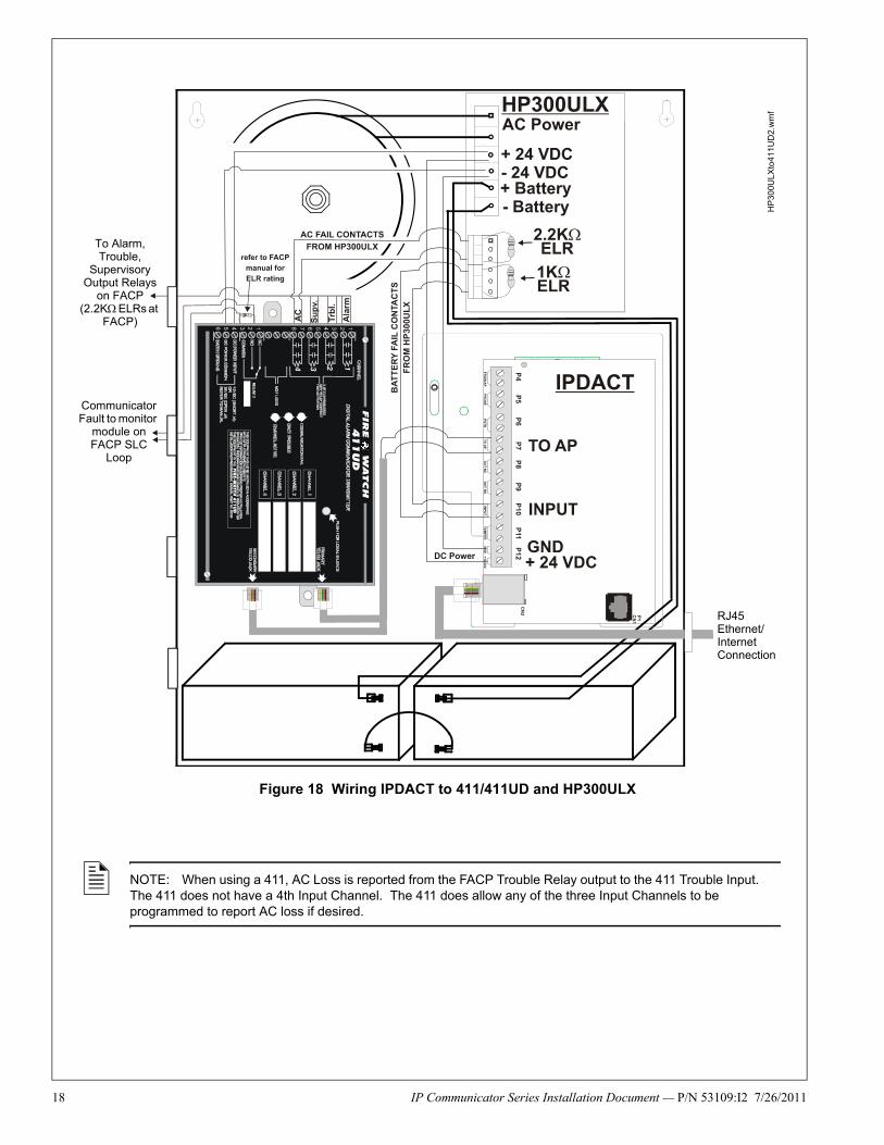
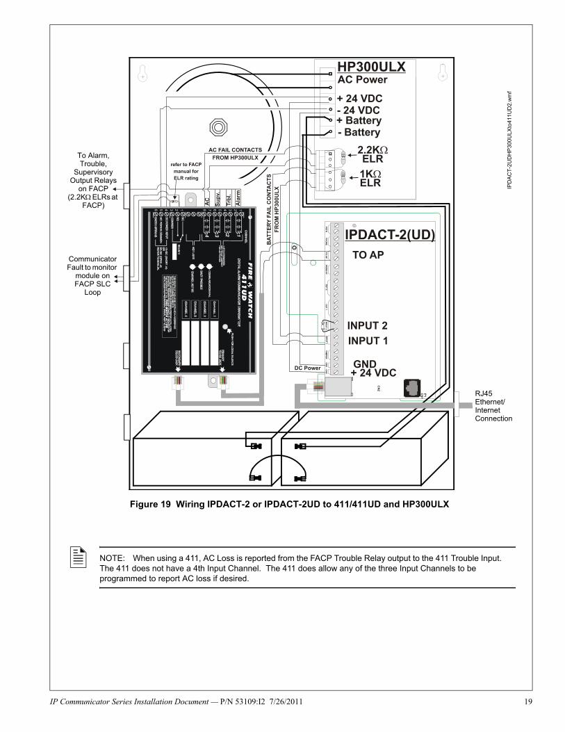
Wiring 411 or 411UD and IPDACT Series to the HP300ULX Power Supply and FACP
Refer to Figure 18 on page 18 (IPDACT) or Figure 19 on page 19 (IPDACT-2/UD) for wiring details.
1. Connect the AC power terminals of the FACP and HP300ULX Power Supply to the same AC power main feed. A loss of AC power will cause the 411/411UD to generate an AC Power Loss indication which will be recognized as an AC power loss for both panels.
2. Connect one end of the supplied phone cable to the Primary and Secondary Telco Jack on the 411/411UD.
3. Wire the other end of the supplied phone line cable to the TO AP terminals of the IPDACT Series as illustrated in Figure 18 on page 18 for the IPDACT or Figure 19 on page 19 for the IPDACT-2 and IPDACT-2UD and in Figures 5 or 6 of this document.
4. Connect Nonresettable 24 VDC power from the HP300ULX to the power terminals on the IPDACT and to the power terminals on the 411/411UD as illustrated in Figure 18 or Figure 19.
5. Connect one wire from the Battery Fail NO (Normally Open) contact of the HP300ULX to one of the Input terminals on the IPDACT Series and a second wire from the Battery Fail C (Common) contact of the HP300ULX to the other Input terminal on the IPDACT Series. This will allow the IPDACT auxiliary trouble input terminals to monitor for an HP300ULX battery failure.
6. Install a 1K ELR across the Battery Fail NO (Normally Open) contact and the C (Common) contact to allow the IPDACT Series to supervise the wiring.
7. Connect the RJ45 connector on the IPDACT Series to an Ethernet/Internet connector.
8. For the 411UD only, connect one wire from the AC Fail NO (Normally Open) contact of the HP300ULX to one of the Channel 4 Input terminals on the 411UD and a second wire from the AC Fail C (Common) contact of the HP300ULX to the other Channel 4 Input terminal on the 411UD. Program the 411UD Input Channel 4 to monitor for an HP300ULX AC failure (factory default).
9. For the 411UD only, install a 2.2K ELR across the AC Fail NO (Normally Open) contact and the C (Common) contact to allow the 411UD to supervise the wiring.
10. Connect a pair of wires from the Channel 1 Input terminals on the 411/411UD to the FACP Alarm Relay C (Common) and NO (Normally Open) Contacts and program the 411/411UD Channel 1 to monitor for alarms.
11. Install a 2.2K ELR across the FACP Alarm Relay C (Common) and NO (Normally Open) contacts to allow the 411/411UD to supervise the wiring.
12. Connect a pair of wires from the Channel 2 Input terminals on the 411/411UD to the FACP Trouble Relay C (Common) and NO (Normally Open) Contacts and program the 411/411UD Channel 1 to monitor for troubles.
13. Install a 2.2K ELR across the FACP Trouble Relay C (Common) and NO (Normally Open) contacts to allow the 411/411UD to supervise the wiring.
14. Connect a pair of wires from the Channel 3 Input terminals on the 411/411UD to the FACP Supervisory Relay C (Common) and NO (Normally Open) Contacts and program the 411/411UD Channel 1 to monitor for supervisory conditions.
15. Install a 2.2K ELR across the FACP Supervisory Relay C (Common) and NO (Normally Open) contacts to allow the 411/411UD to supervise the wiring.
16. Connect a pair of wires between the NO (Normally Open) and C (Common) Trouble Relay on the 411/411UD and an addressable monitor module on the FACP SLC Loop. Program the module to monitor for 411/411UD communicator fault.
17. Refer to the appropriate FACP manual for power specifications and wiring details.
NOTE: Tip & Ring wire connections for TO AP terminal are interchangeable.
18 IP Communicator Series Installation Document — P/N 53109:I2 7/26/2011
NOTE: When using a 411, AC Loss is reported from the FACP Trouble Relay output to the 411 Trouble Input. The 411 does not have a 4th Input Channel. The 411 does allow any of the three Input Channels to be programmed to report AC loss if desired.
RJ45 Ethernet/Internet Connection
Communicator Fault to monitor
module on FACP SLC
Loop
To Alarm, Trouble,
Supervisory Output Relays
on FACP (2.2K ELRs at
FACP)
Figure 18 Wiring IPDACT to 411/411UD and HP300ULX
HP
300U
LX
to4
11U
D2
.wm
f
IP Communicator Series Installation Document — P/N 53109:I2 7/26/2011 19
NOTE: When using a 411, AC Loss is reported from the FACP Trouble Relay output to the 411 Trouble Input. The 411 does not have a 4th Input Channel. The 411 does allow any of the three Input Channels to be programmed to report AC loss if desired.
RJ45 Ethernet/Internet Connection
Communicator Fault to monitor
module on FACP SLC
Loop
To Alarm, Trouble,
Supervisory Output Relays
on FACP (2.2K ELRs at
FACP)
Figure 19 Wiring IPDACT-2 or IPDACT-2UD to 411/411UD and HP300ULXIP
DA
CT
-2U
DH
P30
0ULX
to4
11U
D2
.wm
f