IP Ceiling Speaker for SIP Endpoint Paging or Multicast ... · PRODUCT MANUAL Designed, ... • Can...
18
PRODUCT MANUAL Designed, Manufactured and Supported in the USA SECURITY & COMMUNICATION SOLUTIONS VIKING Specifications Information: 715-386-8861 www.VikingElectronics.com • PoE powered (class 2, <6.5 watts) • Paging prioritization • Plays audio from multicast • SIP endpoint or multicast group member • Supports up to 10 multicast paging groups • Blue paging status LED indicator • SIP compliant (see page 2 for compatible IP-PBX phone systems) • Automatic Noise Canceling (ANC) feature for clear audio - even in noisy environments • Autoprovisioning via Viking programming software • Built-in high efficiency 4 watt class D amplifier • SIP/Multicast: SIP page, SIP page and zoned multicast stream, zoned multicast receive • Support for access code to prevent unwanted SIP calls • Line-level audio output for connecting to an external amplifier • Network remote speaker volume control • Can drive additional external analog speakers for greater coverage • Mounting: Blind mounts into 9.5” hole, clearance requirement of 3.45” (87.3mm) above 1/2” gypsum board ceiling • Heavy duty back box protects speaker and circuitry from plenum dust Power: PoE class 2 (<6.5 watts) Dimensions: Overall: 11” x 11” x 4” (279mm x 279mm x 102mm) Back box: 9.25” x 9.25” x 3.45” (235mm x 235mm x 88mm) Shipping Weight: 5.0 lbs (2.27 kg) Operating Temperature: -40°F to 140°F (-40° C to 60° C) Humidity - Standard Products: 5% to 95% non-condensing Audio Codecs: G711u, G722 and G711a (SIP only) Network Compliance: IEEE 802.3 af PoE, SIP 2.0 RFC3261, 100BASE-TX with auto cross over Connections: (1) RJ45 10/100 Base-T, (1) 8 position terminal block Sensitivity: 96dB / 1W / 1M S.P. Level The Viking model 40-IP Ceiling/Wall Speaker enables SIP endpoint paging and also allows for standard paging and background music via multicast. The speaker easily connects with a single CAT5/6 cable from your PoE switch. Its shallow depth allows the speaker to be conveniently mounted in a standard 2” x 4” stud wall or ceiling. Line-level audio output connections are provided for connecting to an external amplifier. Speaker output connections are also provided to directly drive additional analog speakers. The LED on the 40-IP can be programmed to light during paging. • Amplified SIP endpoint or multicast IP paging for: schools, hospitals, retail stores, office spaces, etc. • Provide background music and sound masking • Add programmable secure relay control with optional RC-4A see DOD# 582 40-IP SIP / Multicast Ceiling Speaker April 3, 2017 IP Ceiling Speaker for SIP Endpoint Paging or Multicast Paging / Background Music Applications Installation requires a Network Administrator / IT Technician ! Model 40-IP (front view) (side view) Features
Transcript of IP Ceiling Speaker for SIP Endpoint Paging or Multicast ... · PRODUCT MANUAL Designed, ... • Can...
PRODUCT MANUALDesigned, Manufactured and Supported in the USA
S E C U R I T Y & C O M M U N I C AT I O N S O L U T I O N S
VIKING
Specifications
Information: 715-386-8861
www.VikingElectronics.com
• PoE powered (class 2, <6.5 watts)• Paging prioritization • Plays audio from multicast• SIP endpoint or multicast group member• Supports up to 10 multicast paging groups• Blue paging status LED indicator • SIP compliant (see page 2 for compatible IP-PBX phone systems)• Automatic Noise Canceling (ANC) feature for clear audio - even in
noisy environments• Autoprovisioning via Viking programming software • Built-in high efficiency 4 watt class D amplifier• SIP/Multicast: SIP page, SIP page and zoned multicast stream, zoned
multicast receive • Support for access code to prevent unwanted SIP calls• Line-level audio output for connecting to an external amplifier• Network remote speaker volume control• Can drive additional external analog speakers for greater coverage• Mounting: Blind mounts into 9.5” hole, clearance requirement of 3.45”
(87.3mm) above 1/2” gypsum board ceiling• Heavy duty back box protects speaker and circuitry from plenum dust
Power: PoE class 2 (<6.5 watts)Dimensions:
Overall: 11” x 11” x 4” (279mm x 279mm x 102mm)Back box: 9.25” x 9.25” x 3.45” (235mm x 235mm x 88mm)
Shipping Weight: 5.0 lbs (2.27 kg)Operating Temperature: -40°F to 140°F (-40° C to 60° C)Humidity - Standard Products: 5% to 95% non-condensingAudio Codecs: G711u, G722 and G711a (SIP only)Network Compliance: IEEE 802.3 af PoE, SIP 2.0 RFC3261,100BASE-TX with auto cross overConnections: (1) RJ45 10/100 Base-T, (1) 8 position terminalblockSensitivity: 96dB / 1W / 1M S.P. Level
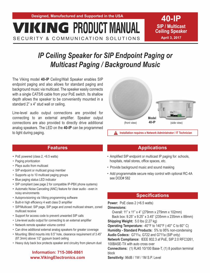
The Viking model 40-IP Ceiling/Wall Speaker enables SIPendpoint paging and also allows for standard paging andbackground music via multicast. The speaker easily connectswith a single CAT5/6 cable from your PoE switch. Its shallowdepth allows the speaker to be conveniently mounted in astandard 2” x 4” stud wall or ceiling.
Line-level audio output connections are provided forconnecting to an external amplifier. Speaker outputconnections are also provided to directly drive additionalanalog speakers. The LED on the 40-IP can be programmedto light during paging.
• Amplified SIP endpoint or multicast IP paging for: schools,hospitals, retail stores, office spaces, etc.
• Provide background music and sound masking• Add programmable secure relay control with optional RC-4A
see DOD# 582
40-IPSIP / Multicast
Ceiling SpeakerApril 3, 2017
IP Ceiling Speaker for SIP Endpoint Paging or Multicast Paging / Background Music
Applications
Installation requires a Network Administrator / IT Technician!
Model40-IP(front view) (side view)
Features

2
Viking VoIP SIP System Compatibility List
* Note: Not compatible with ShoreTel Ring Group/Hunt Group (unit can be programmed to ring an extension 2 or 3 times then roll to the next number, fora total of 5 numbers).
** Note: Relay operation commands are Not compatible with Panasonic Phone Systems (Panasonic does not transmit DTMF between station ports).
Known Incompatible System or Service Provider: Ring Central (Requires Authorization ID and Proxy address).
NOTE: Exclusion from this list means only that compatibility has not been verified, it does not mean incompatibility.
For detailed configuration instructions for certain vendors below, see Configuring Viking VoIP Phone and SIP
Servers, DOD# 944.
Vendor
Infrastructure Class
Softswitch PBX ProxySBC
(session border
controller)
Service
Provider
3COM VCX X
3CX X
Aastra X
Asterisk X
Atcom X
Avaya Aura Communication Manager X
Avaya IP Office X
BlueBox X
Brekeke X
Callcentric X
Cisco Unified Communications Manager (CUCM) X X
Cisco Unified Communications Manager Express
(CUCME)X X
Elastix X
Epygi QX200 X
Freeswitch X
Grandstream X
Interactive Intelligence X X
iPECS (Ericsson-LG) X
iptel.org X
Kamailio X X
MetaSwitch X X
NEC X
OfficeSIP X
OpenSIPS X
Panasonic** (with SIP Extension Card) X
Samsung Communications Manager (SCM) X X
ShoreTel* X
Siemens Communications Server (SCS) X
SIP Express Router (SER) X X
sip.antisip.com X
Snom PBX X
Sonus X
Switchvox X X
Teksip X
Toshiba X
VoIP.ms X
3
Definitions
Client: A computer or device that makes use of a server. As an example, the client might request a particular file from the server.
DHCP: Dynamic Host Configuration Protocol. In this procedure the network server or router takes note of a client’s MAC address and
assigns an IP address to allow the client to communicate with other devices on the network.
DNS Server: A DNS (Domain Name System) server translates domain names (ie: www.vikingelectronics.com) into an IP address.
Ethernet: Ethernet is the most commonly used LAN technology. An Ethernet Local Area Network typically uses twisted pair wires to
achieve transmission speeds up to 1Gbps.
Host: A computer or device connected to a network.
Host Name: A host name is a label assigned to a device connected to a computer network that is used to identify the device in various
forms of network communication.
Hosts File: A file stored in a computer that lists host names and their corresponding IP addresses with the purpose of mapping addresses
to hosts or vice versa.
Internet: A worldwide system of computer networks running on IP protocol which can be accessed by individual computers or networks.
IP: Internet Protocol is the set of communications conventions that govern the way computers communicate on networks and on the
Internet.
IP Address: This is the address that uniquely identifies a host on a network.
LAN: Local Area Network. A LAN is a network connecting computers and other devices within an office or building.
Lease: The amount of time a DHCP server reserves an address it has assigned. If the address isn’t used by the host for a period of
time, the lease can expire and the address can be assigned to another host.
MAC Address: MAC stands for Media Access Control. A MAC address, also called a hardware address or physical address, is a unique
address assigned to a device at the factory. It resides in the device’s memory and is used by routers to send network traffic to the correct
IP address. You can find the MAC address of your 40-IP phone printed on a white label on the top surface of the PoE LAN port.
Router: A device that forwards data from one network to another. In order to send information to the right location, routers look at IP
Address, MAC Address and Subnet Mask.
RTP: Real-Time Transport Protocol is an Internet protocol standard that specifies a way for programs to manage the real-time transmission
of multimedia data over either unicast or multicast network services.
Server: A computer or device that fulfills requests from a client. This could involve the server sending a particular file requested by the
client.
Session Initiation Protocol (SIP): Is a signaling communications protocol, widely used for controlling multimedia communication sessions
such as voice and video calls over Internet Protocol (IP) networks. The protocol defines the messages that are sent between endpoints,
which govern establishment, termination and other essential elements of a call.
Static IP Address: A static IP Address has been assigned manually and is permanent until it is manually removed. It is not subject to the
Lease limitations of a Dynamic IP Address assigned by the DHCP Server. The default static IP Address is: 192.168.154.1
Subnet: A portion of a network that shares a common address component. On TCP/IP networks, subnets are defined as all devices
whose IP addresses have the same prefix. For example, all devices with IP addresses that start with 100.100.100. would be part of the
same subnet. Dividing a network into subnets is useful for both security and performance reasons. IP networks are divided using a subnet
mask.
TCP/IP: Transmission Control Protocol/Internet Protocol is the suite of communications protocols used to connect hosts on the Internet.
TCP/IP uses several protocols, the two main ones being TCP and IP. TCP/IP is built into the UNIX operating system and is used by the
Internet, making it the de facto standard for transmitting data over networks.
TISP: Telephone Internet Service Provider
WAN: Wide Area Network. A WAN is a network comprising a large geographical area like a state or country. The largest WAN is the
Internet.
Wireless Access Point (AP): A device that allows wireless devices to connect to a wired network using Wi-Fi, or related standards. The
AP usually connects to a router (via a wired network) as a standalone device, but it can also be an integral component of the router itself.
Wireless Repeater (Wireless Range Extender): takes an existing signal from a wireless router or access point and rebroadcasts it to
create a second network. When two or more hosts have to be connected with one another over the IEEE 802.11 protocol and the distance
is too long for a direct connection to be established, a wireless repeater is used to bridge the gap.

4
Features Overview
Speaker: 8” paper with wizzer cone
Blue Call/Status LED: Flashes during dialing, then lights steady when answered.
Front View
SpeakerOut
MAC Address Label: The MAC address is a unique 12 digit number used by routers to send network traffic to the correct IP address.
PoE LAN Port 10/100, PoE Class 2 (<6.5 Watts): Connect to your LAN via RJ45 plug and CAT5 or greater twisted pair wire.
Yellow Network Status LED: Lights steady to indicate power and data link. Blinks to indicate network activity.
Green Unit Status LED
+-
- OR -
- OR-
Line Out
Side View
Remove jumper wire when adding Speakers
Adjustable Mounting Clamps
VIKING©VIKING
ELECTRONICSHUDSON, WI 54016
60 WATT 2 ZONEPOWER AMPLIFIER
PWR
60
W+/
24
VD
C
MODEL PA-60
SPK
RS
PWRLED
SPK
RS
LIN
E LE
VEL
A
UD
IO IN
PUT
GAIN GAIN
70V OUT
SPK
RS
SPK
RS
LIN
E LE
VEL
AU
DIO
INPU
T
70V OUT
CHANNEL 2 CHANNEL 1
2 31 5 7 10 11 124 6 8 9
Up to (15)8 Ohm Speakers(25AE shown,not included)
Up to (15)8 Ohm Speakers(30AE shown,not included)
Up to (15)8 Ohm Speakers(35AE shown,not included)
Up to (15)8 Ohm Speakers(40AE shown,not included)
600 OhmPaging Audio
VolumeControl
Optional Viking Model 40AE analog speakers
See DOD# 498
Optional Viking Model PA-60 paging amplifier See DOD# 493

5
Installation and Mounting
Ceiling or Wall Installation
The 40-IP Ceiling Speaker is intended to be mounted in a T-bar acoustic tile, gypsum ceiling or wall.
An optional T-Bar support bracket (SA-TBA) is available that can transfer the speaker weight onto
the T-bar rails. Installation instructions are provided with the support bracket. The metal protective
speaker grill must be removed to access the four Phillips head screws that operate the four clamps.
A small wire speaker grill removal tool is provided to remove the grill. The clamp screws must be
sufficiently loose to allow clamps to rotate and clear the ceiling material thickness. When tightened,
the clamps are locked to prevent rotating. Removal of the speaker from the ceiling requires the
clamps to be sufficiently loosened before they can rotate in to pass through the 9.5” hole required
in the ceiling. The wiring connections are easiest made prior to mounting if possible. Network
connection is made by inserting a RJ45 plug into the jack on the side of the housing. Wire
connections for relay input, switch input, speaker output and line level output (if used) are made
using the 8 position pluggable terminal block provided. The back box helps prevent plenum dust
from entering the enclosure. With connections made, lift the housing into the ceiling and tighten the
4 clamps using a #2 Phillips screwdriver until snug. After installation and testing the speaker grill
can then be fastened by adding grill adhesive (provided with grill removal tool) to 4 edges of grill
then gently working the speaker grill into its friction fit position and ensure it is evenly flush to the
housing around the edge. The speaker grill is intentionally tight to prevent falling from the ceiling. A
speaker grill removal tool supplied with the 40-IP Ceiling Speaker can be used to remove the grill.
If lost, a small Allen key or heavy duty paperclip bent into an L shape can be used to remove the
grill by pulling close to the edge.

6
Switch
SIP VoIP PBX, SIP Cloud based Service Provider
orPC with SIP
Server Software
Internet
PoESwitch
LED 8LED 7LED 6
LED 4
LED 3LED 2LED 1 LED 5
LED 9
1 2 3
on
4
1 2 3 4
VIKINGELECTRONICS
HUDSON, WI 54016
NETWORK ENABLEDRELAY CONTROLLER
MODEL RC-4A©VIKING
1IN1 C IN2 IN3 C IN4
2 3 4 5 6POW
ER 1
2V D
C
RELAY 1 RELAY 2 RELAY 3 RELAY 4
1 2 3 4 5 7 8 9 10 11 12
STATUSLED
6 NETWORK
LOGIC LEVELPROGRAMMINGRESTORE DEFAULTSSPARE
12V DC Adapter(included)
SensorExamples:
Door Sensor
Gate Sensor
Door Sensor
Door Sensor
N.O.
COM.
Connect to Doorstrike,Mag Lock, Gate Controller, etc.
2 Gel-Filled ButtConnectors (included)
Doorstrike / Magnetic Lock
120V AC
Door / Gate Examples:
Door near Entry Phone 1
N.O.
COM.
2 Gel-Filled ButtConnectors (included)
(Power typically notrequired for gate controllers)
Gate Controller
40-IPSpeaker 1
40-IPSpeaker 2
40-IPSpeaker 3
40-IPSpeaker 4
Relay 2 Output Contacts (5A@30VDC / 250VAC max)Connect to Gate Controller, etc.
Gate near Entry Phone 1
N.O.
COM.
2 Gel-Filled ButtConnectors (included)
Doorstrike / Magnetic Lock
120V AC
Door near Entry Phone 2
N.O.
COM.
Relay 4 Output Contacts (5A@30VDC / 250VAC max) Connect to Doorstrike,
Mag Lock, Gate Controller, etc.
2 Gel-Filled ButtConnectors (included)
Doorstrike / Magnetic Lock
120V AC
Door near Entry Phone 3
1IN1 C IN2 IN3 C IN4
2 3 4 5 6
Relay 1 Output Contacts (5A@30VDC / 250VAC max)
Connect to Doorstrike,Mag Lock, Gate Controller, etc.
Relay 3 Output Contacts (5A@30VDC / 250VAC max)
For applications requiring secure relay control a Viking model RC-4A remote relay controller can be used. The relay controller
is mounted securely inside the building and connected to the same LAN as the 40-IP. The 40-IP will send an encrypted
message to the RC-4A to activate its relays which control the door strikes/gates.
Up to 4 40-IP’s can communicate with one RC-4A allowing you to securely control four entrances.
When using an RC-4A for remote relay control the 40-IP’s relays should be set to “External” in the PC programming.
Note: If the 40-IP loses communications with the RC-4A, the LED on the front panel of the 40-IP will flash 3 times every 2seconds indicating the communication error. If this error occurs, make sure the RC-4A is powered, has a network connectionand has the correct IP address and security code of the 40-IP displaying errors.
Adding an optional Viking Model RC-4A For Secure Remote Relay Control
Applications and Wiring

7
• IBM compatible personal computer with:
Windows 2000 (service pack 4 or higher)
Windows XP (service pack 2 or higher)
Windows Vista (SP2 or newer), 32 or 64 bit versions
Windows 7
Windows 8
Windows 10
PC Requirements
PC Programming
A DVD is included with each 40-IP. The DVD contains the application “Viking IP Programming” used to program the unit
using a PC running Windows 2000, XP, Vista, Windows 7, Windows 8 or Windows 10 (see System Requirements above).
The PC must be connected to the same LAN as the 40-IP. Install the application on your PC by placing the DVD into your
PC’s drive. Click “I Accept” on the bottom of the first screen, then select “Viking IP Programming” and click the “Install” button.
Follow the directions on the screen. To start the Viking IP Programming application, click on the Viking IP Programming icon
on your desk top. The Main screen will appear, allowing the user to program any 40-IP connected to that LAN.
Typical Installation on SIP Based VoIP Phone System
SIP VoIP PBXor
PC withSIP ServerSoftware
100m (328 ft) maximum*
Viking supplies
Customer’s Responsibility
Internet
10/100 MbpsMaximum
Viking40-IP
* Note: A PoE extender can be used for an additional 100 meters per extender. For longer runs (up to 2 km / 1.2 miles) a ethernet to fiber media converter can be used.
OptionalPoE Injector
(If VoIP PBX does not have PoE) Optional
Switch / Hub
Optional Viking model RC-4A Secure Remote Relay Controller, see page 6 (DOD# 582)
(Extends range of cable, keeps 1 Gbps network speed for other
equipment on network)
• Adobe Acrobat Reader 8 or higher
• 40-IP hardware
• Available LAN with PoE (class 2, <6.5 watts)
• Ethernet cable ( CAT5 min.)
• 1 MB minimum free hard drive space for installation
• 16MB of free physical RAM
8
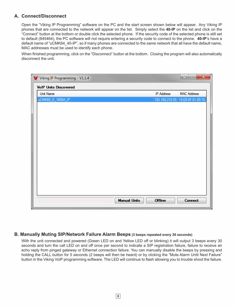
B. Manually Muting SIP/Network Failure Alarm Beeps (3 beeps repeated every 30 seconds)
With the unit connected and powered (Green LED on and Yellow LED off or blinking) it will output 3 beeps every 30
seconds and turn the call LED on and off once per second to indicate a SIP registration failure, failure to receive an
echo reply from pinged gateway or Ethernet connection failure. You can manually disable the beeps by pressing and
holding the CALL button for 5 seconds (2 beeps will then be heard) or by clicking the “Mute Alarm Until Next Failure”
button in the Viking VoIP programming software. The LED will continue to flash allowing you to trouble shoot the failure.
A. Connect/Disconnect
Open the “Viking IP Programming” software on the PC and the start screen shown below will appear. Any Viking IP
phones that are connected to the network will appear on the list. Simply select the 40-IP on the list and click on the
“Connect” button at the bottom or double click the selected phone. If the security code of the selected phone is still set
to default (845464), the PC software will not require entering a security code to connect to the phone. 40-IP’s have a
default name of “uCMK64_40-IP”, so if many phones are connected to the same network that all have the default name,
MAC addresses must be used to identify each phone.
When finished programming, click on the “Disconnect” button at the bottom. Closing the program will also automatically
disconnect the unit.
9
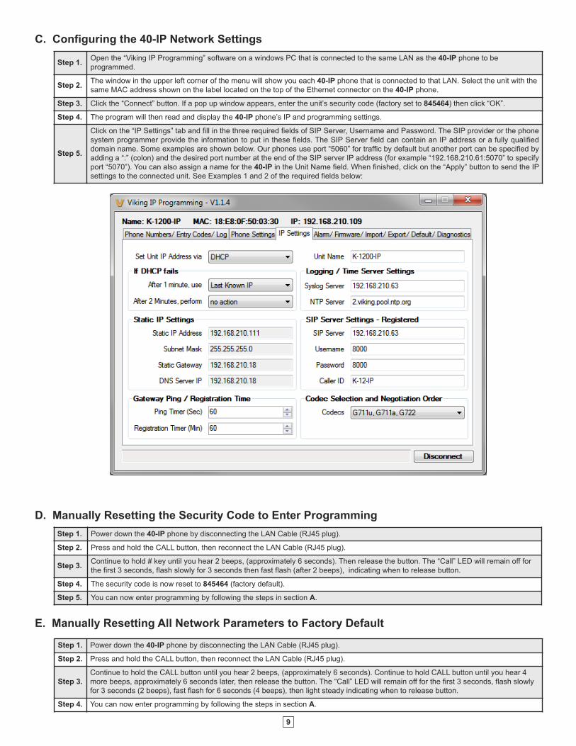
C. Configuring the 40-IP Network Settings
Step 1.Open the “Viking IP Programming” software on a windows PC that is connected to the same LAN as the 40-IP phone to be
programmed.
Step 2.The window in the upper left corner of the menu will show you each 40-IP phone that is connected to that LAN. Select the unit with the
same MAC address shown on the label located on the top of the Ethernet connector on the 40-IP phone.
Step 3. Click the “Connect” button. If a pop up window appears, enter the unit’s security code (factory set to 845464) then click “OK”.
Step 4. The program will then read and display the 40-IP phone’s IP and programming settings.
Step 5.
Click on the “IP Settings” tab and fill in the three required fields of SIP Server, Username and Password. The SIP provider or the phone
system programmer provide the information to put in these fields. The SIP Server field can contain an IP address or a fully qualified
domain name. Some examples are shown below. Our phones use port “5060” for traffic by default but another port can be specified by
adding a “:” (colon) and the desired port number at the end of the SIP server IP address (for example “192.168.210.61:5070” to specify
port “5070”). You can also assign a name for the 40-IP in the Unit Name field. When finished, click on the “Apply” button to send the IP
settings to the connected unit. See Examples 1 and 2 of the required fields below:
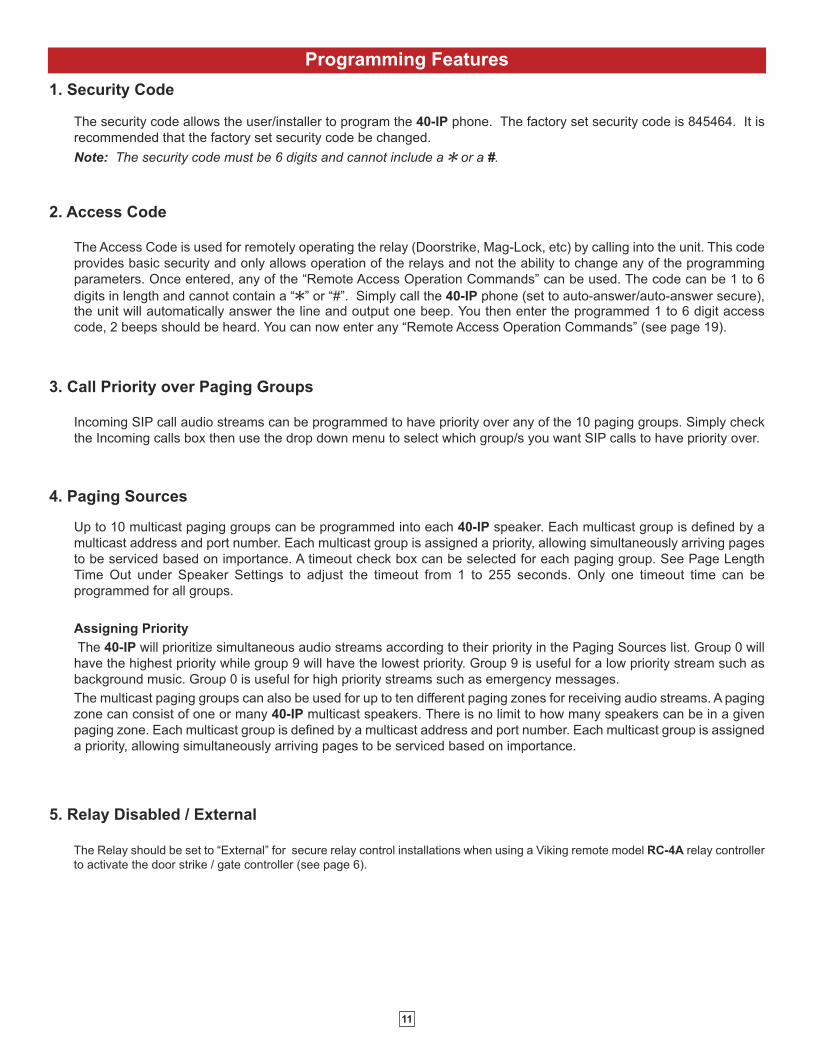
Step 1. Power down the 40-IP phone by disconnecting the LAN Cable (RJ45 plug).
Step 2. Press and hold the CALL button, then reconnect the LAN Cable (RJ45 plug).
Step 3.Continue to hold # key until you hear 2 beeps, (approximately 6 seconds). Then release the button. The “Call” LED will remain off for
the first 3 seconds, flash slowly for 3 seconds then fast flash (after 2 beeps), indicating when to release button.
Step 4. The security code is now reset to 845464 (factory default).
Step 5. You can now enter programming by following the steps in section A.
D. Manually Resetting the Security Code to Enter Programming
E. Manually Resetting All Network Parameters to Factory Default
Step 1. Power down the 40-IP phone by disconnecting the LAN Cable (RJ45 plug).
Step 2. Press and hold the CALL button, then reconnect the LAN Cable (RJ45 plug).
Step 3.
Continue to hold t he CALL button until you hear 2 beeps, (approximately 6 seconds). Continue to hold CALL button until you hear 4
more beeps, approximately 6 seconds later, then release the button. The “Call” LED will remain off for the first 3 seconds, flash slowly
for 3 seconds (2 beeps), fast flash for 6 seconds (4 beeps), then light steady indicating when to release button.
Step 4. You can now enter programming by following the steps in section A.

10
Programming Features Index
DESCRIPTION Section Page
Connect/Disconnect A 8
Security code (factory set to 845464) 1 11
Access Code (1-6 digits, blank = disabled, factory set to 123456) 2 11
Call Priority over Paging Groups 3 11
Paging Sources 4 11
Disabled / External Relay (factory set to disabled) 5 11
Relay Mode (Door Strike, Outbound Call, In/Outbound Call, Doorbell, Alarm Mode, factory set to Door Strike) 6 12
Relay Command (1 or 2 digits, factory set to QQ and Q2) (Relay Mode must be set to Door Strike) 7 12
Relay Time (0.5 - 99 sec, factory set to 5 sec) 8 12
Relay Latch Commands (Enabled or Disabled, factory set to Enabled) 9 12
Speaker Mode 10 12
Call Length Time Out (disabled or 1 to 9 min, factory set to 3 min) 11 12
Page Length Time Out (factory set to disabled 12 12
Inbound Call Mode (Disabled, Auto Answer, Auto Answer-Secure, Silent Monitor, Silent Monitor-Secure) 13 13
Ring Cadence 14 13
LED Mode 15 13
Phone Name 16 13
Mute Current / Next Alarm 17 13
IP Firmware 18 14
Phone Firmware 19 14
Import/Export 20 14
Default Settings 21 14
Diagnostics (used to check mic, speaker, relays and proximity card reader operation) 22 14
Paging Volume
Ring Volume
11
Programming Features
The security code allows the user/installer to program the 40-IP phone. The factory set security code is 845464. It is
recommended that the factory set security code be changed.
Note: The security code must be 6 digits and cannot include a Q or a #.
Incoming SIP call audio streams can be programmed to have priority over any of the 10 paging groups. Simply check
the Incoming calls box then use the drop down menu to select which group/s you want SIP calls to have priority over.
Up to 10 multicast paging groups can be programmed into each 40-IP speaker. Each multicast group is defined by a
multicast address and port number. Each multicast group is assigned a priority, allowing simultaneously arriving pages
to be serviced based on importance. A timeout check box can be selected for each paging group. See Page Length
Time Out under Speaker Settings to adjust the timeout from 1 to 255 seconds. Only one timeout time can be
programmed for all groups.
Assigning Priority
The 40-IP will prioritize simultaneous audio streams according to their priority in the Paging Sources list. Group 0 will
have the highest priority while group 9 will have the lowest priority. Group 9 is useful for a low priority stream such as
background music. Group 0 is useful for high priority streams such as emergency messages.
The multicast paging groups can also be used for up to ten different paging zones for receiving audio streams. A paging
zone can consist of one or many 40-IP multicast speakers. There is no limit to how many speakers can be in a given
paging zone. Each multicast group is defined by a multicast address and port number. Each multicast group is assigned
a priority, allowing simultaneously arriving pages to be serviced based on importance.
1. Security Code
The Access Code is used for remotely operating the relay (Doorstrike, Mag-Lock, etc) by calling into the unit. This code
provides basic security and only allows operation of the relays and not the ability to change any of the programming
parameters. Once entered, any of the “Remote Access Operation Commands” can be used. The code can be 1 to 6
digits in length and cannot contain a “Q” or “#”. Simply call the 40-IP phone (set to auto-answer/auto-answer secure),the unit will automatically answer the line and output one beep. You then enter the programmed 1 to 6 digit access
code, 2 beeps should be heard. You can now enter any “Remote Access Operation Commands” (see page 19).
3. Call Priority over Paging Groups
4. Paging Sources
2. Access Code
5. Relay Disabled / External
The Relay should be set to “External” for secure relay control installations when using a Viking remote model RC-4A relay controller
to activate the door strike / gate controller (see page 6).
12
The one or two digit code stored in the Relay Activation Command is the touch tone command that the person being called must
enter on their phone in order to momentarily activate the relay to control a doorstrike, mag-lock, gate controller, or other device. The
code can contain the characters 0 - 9, # or Q. The code cannot match a relay latching or toggle command (11, 10, 1#). The code
must be entered while the remote phone is communicating with the Speaker phone. The factory setting is QQ.
7. Relay (Activation) Command
The value stored in the Relay Activation Time is the amount of time the relay will be energized after a correct momentary touch tone
command is entered. This number can range from 0.5 to 99 seconds. The factory setting is 5 seconds.
8. Relay Activation Time
When set to “Enabled” (factory default) the Remote Access Operation Commands (Q0 to Q1) to Un-Latch or Latch the relay areenabled.
When set to “Disabled” the Remote Access Operation Commands (Q0 to Q1) to Un-Latch or Latch the relay are disabled. Disablingthe Latch commands can be useful in applications where you want to eliminate the possibility of inadvertently entering a latch
command leaving a gate open/closed, etc.
9. Relay Latch Commands
10. Speaker Mode
The Speaker Mode can be set to one of the following three modes.
OFF Mode: In the “OFF” mode the speaker is disabled at all times. However, the speaker can be enabled after communication has
been established by entering touch tone command “9#”. The speaker will remain on for the duration of the call.
ON (factory setting): In the “ON” mode the speaker is enabled during In-bound and Out-bound calls.
OFF Until Answered: In the “OFF Until Answered” mode the speaker will remain silent during dialing and will not turn on until the
called party has answered.
This feature selects the maximum length of time that calls can be connected. Programmable in increments of 1 minute
up to a maximum of 9 minutes or disabled. With the call length disabled, the 40-IP phone must rely on a call ended
signal, busy signal, silence, Ring No Answer limit, or return to dial tone to hang-up.
Note: The factory default is 3 minutes.
The Paging Length Time Out is factory set to disabled, allowing any length of page or continuous background music. A
time out can also be programmed from 1 to 255 seconds in one second increments. A timeout check box can be selected
for each paging group. Only one timeout time can be programmed for all multicast paging groups.
11. Call Length Time Out
12. Page Length Time Out
Doorstrike Mode: When programmed for Doorstrike Mode the relay is intended for door strike, maglock or gate control.
Outbound Call Mode: When programmed for Outbound Call Mode the relay will activate continuously for the duration of any
outbound call from the Speaker phone.
Inbound/Outbound Call Mode: When programmed for Inbound/Outbound Call Mode the relay will activate continuously for the
duration of any inbound or outbound call to or from the Speaker phone. This mode is useful for turning on IR flood lights, for VoIP
phones with cameras, etc.
Doorbell Mode: When programmed for Doorbell Mode the speaker phone will momentarily activate the relay for the preprogrammed
relay activation time on any outbound call from the speaker phone. This mode is useful for activating a door chime, etc. When
activating door chimes, a 0.5 - 1 second relay activation time is recommended. Note: Activation time must be set before DoorbellMode is selected.
Alarm Mode: When programmed in Alarm Mode the relay will activate continuously while the Speaker phone is powered and
registered to the SIP server. In the event the unit loses power and/or SIP registration the relay will turn off, which can be used to
signal an alarm device.
6. Relay Mode
13
The Inbound Call Mode determines how the 40-IP handles incoming SIP calls. One option is to generate a loud ringsound through the speaker. The 40-IP can also auto answer the call, to allow remote control of the relay and the abilityto transmit a page. The “secure” options for auto answer require the callers to dial the access code in order to transmita page or activate the optional RC-4A relays.
Disabled – Inbound SIP calls are not allowed.
Auto Answer – Inbound SIP calls are auto answered on the first ring.
Auto Answer Secure – Inbound SIP calls are auto answered and the caller must dial the access code in order to listenor talk on the unit.
Ring: In the “Ring” mode the speaker will not automatically answer an incoming call but will output a loud ring signalout of the speaker in a 2 seconds on, 4 seconds off ring pattern. The call can then be answered by momentarily pressingthe call button.
Ring with AGC: In the “Ring with AGC” mode the speaker will not automatically answer an incoming call but will outputa loud ring signal out of the speaker in a 2 seconds on, 4 seconds off ring pattern. The phone will automatically increaseor decrease the ring volume based on background ambient noise. The call can then be answered by momentarilypressing the call button.
13. Inbound Call Mode
14. Ring Cadence
The Ring cadence can be programmed to one of 4 different cadences:
Normal Ring (single ring, 2 sec on 4 sec off)
Double Ring (double ring, 1 sec on .5 sec off 1 sec on 3.5 sec off)
Short-Short-Long (triple ring, .5 sec on .5 sec off .5 sec on .5 sec off 1 sec on 3 sec off)
Short-Long-Short (triple ring, .5 sec on .5 sec off 1 sec on .5 sec off .5 sec on 3 sec off)
The “Call” LED on the 40-IP can be programmed to one of four different modes: OFF, ON, Phone or paging.
OFF Mode: Useful for silent monitoring applications. In this mode the LED will not light during normal operation. It will only light
(blink) if it cannot register with the programmed SIP server or while manually resetting all network parameters to factory default.
On Mode: The LED will remain ON in the idle state, turn off while button is pressed, blink during dialing, light steady when the call
is answered, then turn OFF momentarily when the call is completed.
Phone or Paging Mode: The LED will remain OFF in the idle state, blink during dialing, light steady when the call is connected, then
turn OFF when the call is completed. The LED will also light steady during paging.
15. LED Mode
16. Phone Name
17. Mute Current / Next Alarm
Up to a 31 character phone name can be assigned to the 40-IP being programmed. Often times the building name and
entrance location near the unit are used for the name.
A network failure alarm will be indicated by providing 3 beeps every 30 seconds. A network failure indicates the unit is
not registered to the SIP server or there is a communication failure with the gateway. The three beeps can be muted by
clicking on “Mute Current / Next Alarm”.
14
18. IP Firmware
If new 40-IP firmware is available, after opening the programming software a pop window will come up asking you if
you would like to update firmware. An alternative method of updating can be done by clicking the IP firmware “Update”
button. You can then browse to the folder that contains the PIP file for updating the unit’s IP firmware. This method is
typically only used when Viking Technical Support has sent you updated IP firmware
20. Import/Export
The Import/Export feature is useful for backing up all the 40-IP’s programming or for importing programming when
installing multiple units with a majority of the same programming.
Clicking on the “Default Settings” button in programming will reset all of the Programming Features back to their factory
default settings. Note: This command will not change or reset your IP settings.
21. Default Settings
22. Diagnostics
The Diagnostics section in the Viking IP Programming can be used to test the functionality of the mic, speaker and
relay.
19. Phone Firmware
If new 40-IP firmware is available, after opening the programming software a pop up window will ask if you would like
to update firmware. Another way to update is accomplished by clicking the phone firmware “Update” button. You can
then browse to the folder that contains the HEX file for updating the unit’s firmware. This method is typically only used
when Viking Technical Support has sent you updated firmware.
15
Operation
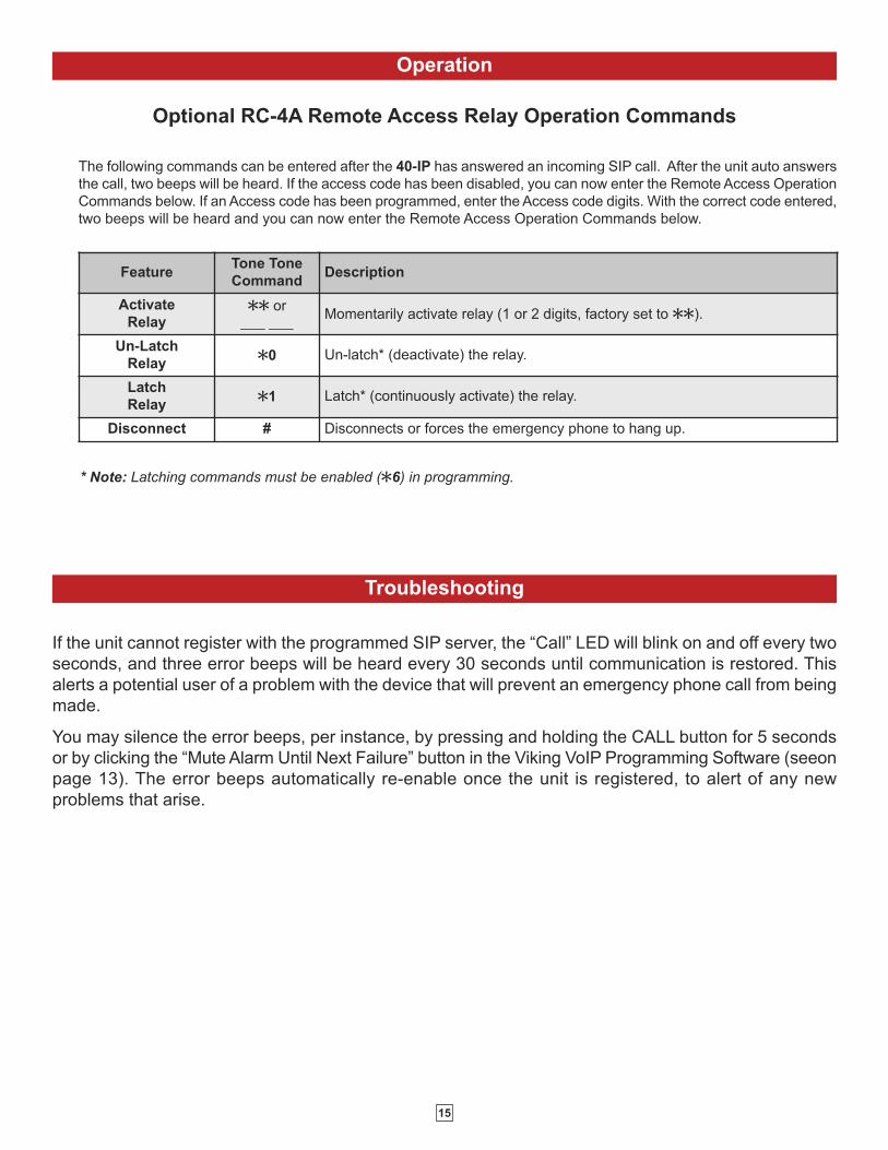
Optional RC-4A Remote Access Relay Operation Commands
FeatureTone Tone
CommandDescription
Activate
RelayQQ or
___ ___Momentarily activate relay (1 or 2 digits, factory set to QQ).
Un-Latch
RelayQ0 Un-latch* (deactivate) the relay.
Latch
RelayQ1 Latch* (continuously activate) the relay.
Disconnect # Disconnects or forces the emergency phone to hang up.
* Note: Latching commands must be enabled (Q6) in programming.
The following commands can be entered after the 40-IP has answered an incoming SIP call. After the unit auto answers
the call, two beeps will be heard. If the access code has been disabled, you can now enter the Remote Access Operation
Commands below. If an Access code has been programmed, enter the Access code digits. With the correct code entered,
two beeps will be heard and you can now enter the Remote Access Operation Commands below.
Troubleshooting
If the unit cannot register with the programmed SIP server, the “Call” LED will blink on and off every two
seconds, and three error beeps will be heard every 30 seconds until communication is restored. This
alerts a potential user of a problem with the device that will prevent an emergency phone call from being
made.
You may silence the error beeps, per instance, by pressing and holding the CALL button for 5 seconds
or by clicking the “Mute Alarm Until Next Failure” button in the Viking VoIP Programming Software (seeon
page 13). The error beeps automatically re-enable once the unit is registered, to alert of any new
problems that arise.

16
Related Products
30AE/35AE Ceiling Speakers
• Metal white grill for flush mounting in
office ceilings
• Mounting hardware included
• Excellent frequency response
• The 35AE includes a volume control
25AE Paging Horn
• Adjustable base for easy
mounting and directional
adjustment
• Compact design for
discreet mounting
300AE Paging Horn
• 30 Watt 8 ohm / 70V
Paging Horn
40AE Ceiling Speakers
• Attractive with a modern look
• Flush mounts into a 9.5” to 10”
diameter hole
• Integral mounting system
• Excellent sound quality
Control Relay Contacts Across a Local Area Network
Viking Analog Speakers
The RC-4A Network Enabled Relay Controller provides networked control of four relays via an easy-
to-use web interface. The same interface can be used to check the status of four contact closure
inputs. Relays can be toggled on or off, or user-programmed timed closures can be activated.
The RC-4A can be configured to work as a remote relay for Viking VoIP series entry phones,
controlling door strikes and gates when a remote relay is required for security reasons. It can also be
programmed to send an email or text message in response to a change in one or more of the sensor
inputs. Two RC-4A’s can be set up so that activity on a sensor input of one unit will automatically
send a message across the network to activate one of the relays on the other unit. Two levels of user
access permit selected users to have full operational and programming rights while others have
operational control but not programming capability. For more info, see DOD# 585
Tile Bridge for Ceiling SpeakersThe SA-TBA is a tile bridge designed to mount 8 inch loud
speaker and bridges both 2 ft x 2 ft and 2 ft x 4 ft ceiling tiles.
It is compatible with the Viking models SA-1S, 30AE, 35AE,
and 40AE speakers. The SA-TBA tile bridge is constructed
of 24 gauge cold rolled steel with an electro galvanized rust-
resistant finish.
25AE40AE35AE30AE
The 25AE, 30AE, 35AE, and 40AE paging speakers provide additional economical paging coverage to existing Viking paging
units (40-IP, PA-2A, PA-15, PA-30, PA-60, HF-3W, M2W) or to any system with an 8 ohm output.
In outdoor, factory or warehouse environments, 25AE paging horns are the best method of producing understandable sound.
In these environments the directional design allows the installer to focus the sound cone down aisles and toward work areas.
In office and restaurant environments, it is best to distribute sound more evenly. Ceiling mounted 30AE, 35AE, or 40AE
speakers in close proximity offer the best distribution and are cost effective. The 35AE speakers include a volume control.
300AE

17
Related Products
60 Watt Compact Two Zone Amplifier to Drive up to 60 Paging Speakers
The PA-60 can directly drive up to sixty (60) 8 ohm paging speakers or one hundred (100) 70 volt or
25 volt paging speakers. Both channels can be fed the same input so the PA-60 can be used as a
single large amplifier, or each channel can be fed different inputs so the PA-60 can be used as a two
zone amplifier.
This small and lightweight chassis design is possible by utilizing new amplifier technology that is 300%
less inefficient than old designs competitors use. High efficiency means much less heat disipation,
smaller size, higher reliability, and lower cost.
Since each input has its own gain adjustment, one zone can be turned up louder for warehouse paging
horn speakers, and the other zone can be turned down for office ceiling speakers. Two zones can also
be helpful for installations in which one group of speakers is connected to a source that provides
background music using the Viking PI-1A Paging Interface unit, and the other zone provides only
paging.
The Viking models CTG-1 or CTG-2 can be used to add clock controlled tones with paging to both
zones, or one zone can have just paging and be free of the time scheduled alert tones. The same can
be done with the Viking model MTG-10 in which one zone can have just paging, and the other zone
can have paging plus the 10 different siren, warble, and chime tones that the MTG-10 can provide.
One or two PA-60’s can be added to the Viking model ZPI-4 four zone paging interface to provide
either 60 watts or 120 watts of total paging power in four zones. The PA-60 can also be used to add
additional paging power to other Viking paging products such as the PA-2A, PA-15, and PA-30.
The PA-60’s inputs are transformer coupled so they are floating and isolated. Because of this they can
be connected to any line level audio signal, or by turning down the input gain control to unity gain, can
be connected directly to the output of another amplifier. This allows the PA-60 to be connected directly
to an existing paging system speaker wire run to extend the run, with up to 60 more speakers.
Add Paging, Loud Ringing and Background Music to Centrex, PABX, IP, or Key SystemsThe PA-15 interfaces with virtually any telephone system to provide 15 watts of paging power - enough
to drive fifteen 8-ohm paging horns or speakers. This small and light weight chassis design is possible
by utilizing new amplifier technology that is 300% less inefficient than old designs competitors use.
High efficiency means much less heat disipation, smaller size, higher reliability, and lower cost.
The PA-15 provides 36V talk battery for interfacing with an FXO or unused analog line input/trunk
port. With the flip of a switch, the unit can connect to a FXS or PABX/Centrex station ring trip port or
connect to a 600 ohm paging port. When interfacing with systems that do not provide a paging contact
closure, the built-in voice activation (VOX) is in control.
After paging, the PA-15 auto disconnects on CPC, busy signal, silence, or default disconnect timer
(helps prevent accidental paging system lock-up if phone is hung-up incorrectly). The unit will generate
adjustable loud ringing from an independent ringing analog FXS/PABX/Centrex station or from a dry
contact closure. The PA-15 can provide background music (muted during page) if connected to an
external music source.
Add Paging and Loud Ringing with Background Music to Any Phone System
The PA-30 can directly drive up to thirty (30) 8 ohm paging speakers or fifty (50) 70 volt or 25 volt paging
speakers. This small and light weight chassis design is possible by utilizing new amplifier technology
that is 300% less inefficient than old designs competitors use. High efficiency means much less heat
disipation, smaller size, higher reliability, and lower cost.
The PA-30 provides loud ringing and paging to electronic key systems, 1A2 Key systems, PABX’s as
well as No-KSU phones and multi-line phones.
Paging is accomplished by connecting the PA-30 to a paging port or unused telephone line input (trunk
port) of nearly any phone system.
The PA-30 will also generate adjustable loud ringing from a ringing analog line or from a dry contact
closure. Either a loud electronic warble, or one of three other soft chime sounds may be selected. An
external “night transfer” switch can be added to turn loud ringing on or off in night bell applications.
The PA-30 eliminates the installation of multiple bells, relays and paging cards. The unit comes complete
with a power supply, and integrated 30 watt amplifier.
18
Printed in the U.S.A. ZF303990 REV 5
Due to the dynamic nature of the product design, the information contained in this document is subject to change without notice. Viking Electronics, and its affiliates and/or subsidiaries
assume no responsibility for errors and omissions contained in this information. Revisions of this document or new editions of it may be issued to incorporate such changes.
DOD# 503
Product Support: (715) 386-8666
If trouble is experienced with the 40-IP phone, for repair or warranty information, please contact:
Viking Electronics, Inc., 1531 Industrial Street, Hudson, WI 54016 (715) 386-8666
WHEN PROGRAMMING EMERGENCY NUMBERS AND (OR) MAKING TEST CALLS TO EMERGENCY NUMBERS:Remain on the line and briefly explain to the dispatcher the reason for the call. Perform such tests in off-peak hours, such as early morning or late evenings.
PART 15 LIMITATIONSThis equipment has been tested and found to comply with the limits for a Class A digital device, pursuant to Part 15 of the FCC Rules. These limits are
designed to provide reasonable protection against harmful interference when the equipment is operated in a commercial environment. This equipment
generates, uses, and can radiate radio frequency energy and, if not installed and used in accordance with the instruction manual, may cause harmful
interference to radio communications. Operation of this equipment in a residential area is likely to cause harmful interference in which case the user will
be required to correct the interference at his own expense.
Warranty
IF YOU HAVE A PROBLEM WITH A VIKING PRODUCT, CONTACT: VIKING TECHNICAL SUPPORT AT (715) 386-8666
Our Technical Support Department is available for assistance Monday through Friday 8:00am to 5:00pm central time. So that we can give you better
service, before you call please:
1. Know the model number, the serial number and what software version you have (see serial label).
2. Have your Product Manual in front of you.
3. It is best if you are on site.
RETURNING PRODUCT FOR REPAIRThe following procedure is for equipment that needs repair:
1. Customer must contact Viking's Technical Support Department at 715-386-8666 to obtain a Return Authorization (RA) number. The customer MUST
have a complete description of the problem, with all pertinent information regarding the defect, such as options set, conditions, symptoms, methods to
duplicate problem, frequency of failure, etc.
2. Packing: Return equipment in original box or in proper packing so that damage will not occur while in transit. Static sensitive equipment such as a
circuit board should be in an anti-static bag, sandwiched between foam and individually boxed. All equipment should be wrapped to avoid packing
material lodging in or sticking to the equipment. Include ALL parts of the equipment. C.O.D. or freight collect shipments cannot be accepted. Ship
cartons prepaid to: Viking Electronics, 1531 Industrial Street, Hudson, WI 54016
3. Return shipping address: Be sure to include your return shipping address inside the box. We cannot ship to a PO Box.
4. RA number on carton: In large printing, write the R.A. number on the outside of each carton being returned.
RETURNING PRODUCT FOR EXCHANGEThe following procedure is for equipment that has failed out-of-box (within 10 days of purchase):
1. Customer must contact Viking’s Technical Support at 715-386-8666 to determine possible causes for the problem. The customer MUST be able to
step through recommended tests for diagnosis.
2. If the Technical Support Product Specialist determines that the equipment is defective based on the customer's input and troubleshooting, a Return
Authorization (R.A.) number will be issued. This number is valid for fourteen (14) calendar days from the date of issue.
3. After obtaining the R.A. number, return the approved equipment to your distributor, referencing the R.A. number. Your distributor will then replace the
Viking product using the same R.A. number.
4. The distributor will NOT exchange this product without first obtaining the R.A. number from you. If you haven't followed the steps listed in
1, 2 and 3, be aware that you will have to pay a restocking charge.
TWO YEAR LIMITED WARRANTYViking warrants its products to be free from defects in the workmanship or materials, under normal use and service, for a period of two years from the date of purchase
from any authorized Viking distributor. If at any time during the warranty period, the product is deemed defective or malfunctions, return the product to Viking Electronics,Inc., 1531 Industrial Street, Hudson, WI., 54016. Customer must contact Viking's Technical Support Department at 715-386-8666 to obtain a Return Authorization (R.A.)number.
This warranty does not cover any damage to the product due to lightning, over voltage, under voltage, accident, misuse, abuse, negligence or any damage caused byuse of the product by the purchaser or others. This warranty does not cover non-EWP products that have been exposed to wet or corrosive environments. This warrantydoes not cover stainless steel surfaces that have not been properly maintained.
NO OTHER WARRANTIES. VIKING MAKES NO WARRANTIES RELATING TO ITS PRODUCTS OTHER THAN AS DESCRIBED ABOVE AND DISCLAIMS ANYEXPRESS OR IMPLIED WARRANTIES OR MERCHANTABILITY OR FITNESS FOR ANY PARTICULAR PURPOSE.
EXCLUSION OF CONSEQUENTIAL DAMAGES. VIKING SHALL NOT, UNDER ANY CIRCUMSTANCES, BE LIABLE TO PURCHASER, OR ANY OTHER PARTY,FOR CONSEQUENTIAL, INCIDENTAL, SPECIAL OR EXEMPLARY DAMAGES ARISING OUT OF OR RELATED TO THE SALE OR USE OF THE PRODUCT SOLDHEREUNDER.
EXCLUSIVE REMEDY AND LIMITATION OF LIABILITY. WHETHER IN AN ACTION BASED ON CONTRACT, TORT (INCLUDING NEGLIGENCE OR STRICT LIABILITY)OR ANY OTHER LEGAL THEORY, ANY LIABILITY OF VIKING SHALL BE LIMITED TO REPAIR OR REPLACEMENT OF THE PRODUCT, OR AT VIKING'S OPTION,REFUND OF THE PURCHASE PRICE AS THE EXCLUSIVE REMEDY AND ANY LIABILITY OF VIKING SHALL BE SO LIMITED.
IT IS EXPRESSLY UNDERSTOOD AND AGREED THAT EACH AND EVERY PROVISION OF THIS AGREEMENT WHICH PROVIDES FOR DISCLAIMER OFWARRANTIES, EXCLUSION OF CONSEQUENTIAL DAMAGES, AND EXCLUSIVE REMEDY AND LIMITATION OF LIABILITY, ARE SEVERABLE FROM ANY OTHERPROVISION AND EACH PROVISION IS A SEPARABLE AND INDEPENDENT ELEMENT OF RISK ALLOCATION AND IS INTENDED TO BE ENFORCED AS SUCH.