IP camera tester - Farnell
131
Transcript of IP camera tester - Farnell


Content
1 .Safety information ----------------------------------------------------------------------------------------------------- 1 2. IP Camera Tester Introduction --------------------------------------------------------------------------------------- 2
2.1 General ----------------------------------------------------------------------------------------------------------- 2 2.4 Packing list ------------------------------------------------------------------------------------------------------ 3 2.5 Function interface ---------------------------------------------------------------------------------------------- 4
3. Operation ---------------------------------------------------------------------------------------------------------------- 7 3.1 Installing the Battery ------------------------------------------------------------------------------------------- 7 3.2 Instrument connection ----------------------------------------------------------------------------------------- 8 3.2.1 IP camera connection ---------------------------------------------------------------------------------------- 8 3.2.2 Analog camera connection --------------------------------------------------------------------------------- 9
3.2.3 HD Coaxial camera connection ------------------------------------------------------------------- 10 3.2.4 HDMI IN --------------------------------------------------------------------------------------------- 11
3.3 OSD menu ----------------------------------------------------------------------------------------------------- 11 3.3.1 Lite mode& Normal mode ------------------------------------------------------------------------- 11 3.3.2 Drop-down Menu ------------------------------------------------------------------------------------ 15 3.3.3 Short cut-menu --------------------------------------------------------------------------------------- 16 3.3.4 Screen capture ---------------------------------------------------------------------------------------- 17 3.3.5 TesterPlay --------------------------------------------------------------------------------------------- 17 3.3.6 Rapid video ------------------------------------------------------------------------------------------- 19 3.3.7 IP discovery ------------------------------------------------------------------------------------------- 20 3.3.8 Rapid ONVIF test ------------------------------------------------------------------------------------ 21 3.3.9 IP camera test ---------------------------------------------------- Error! Bookmark not defined. 3.3.10 HDMI IN ( *Optional ) ------------------------------------------------------------------------- 38 3.3.11 Video monitor test---------------------------------------------------------------------------------- 42 3.3.12 Color-bar generator (TV OUT) ------------------------------------------------------------------ 51 3.3.13 SDI Camera Test ( *Optional ) ---------------------------------------------------------------- 53 3.3.14 CVI camera test ( *Optional ) ----------------------------------------------------------------- 54

3.3.15 TVI camera test ( *Optional ) ------------------------------------------------------------------ 61 3.3.16 AHD camera test ( *Optional ) ---------------------------------------------------------------- 63 3.3.17 Network tool ---------------------------------------------------------------------------------------- 64 (1)IP address scan -------------------------------------------------------------------------------------- 64 (2)PING Test -------------------------------------------------------------------------------------------- 65 (3)Network test (Ethernet bandwidth test) --------------------------------------------------------- 66 (4)Port Flashing ----------------------------------------------------------------------------------------- 69 (5)DHCP server ----------------------------------------------------------------------------------------- 70 (6)Trace route ------------------------------------------------------------------------------------------- 71 (7)Link monitor ----------------------------------------------------------------------------------------- 72 3.3.18 Rapid IP Discovery -------------------------------------------------------------------------------- 72 3.3.19 PoE power / DC12V 2A and DC 5V 2A USB power output ------------------------------- 73 3.3.20 Cable Test ------------------------------------------------------------------------------------------- 74 3.3.21 RJ45 cable TDR test ------------------------------------------------------------------------------- 75 3.3.22 Cable Tracer ( *Optional ) -------------------------------------------------------------------- 78 3.3.23 TDR cable test ( *Optional ) ------------------------------------------------------------------- 79 3.3.24 PoE Voltage test ------------------------------------------------------------------------------------ 82 3.3.25 12V power input test ------------------------------------------------------------------------------- 83 3.3.26 Digital Multi-meter ( *Optional ) ------------------------------------------------------------- 84 3.3.27 Optical power meter ( *Optional ) ------------------------------------------------------------ 91 3.3.28 Visual Fault Locator ( *Optional ) ------------------------------------------------------------ 93 3.3.29 Audio Record --------------------------------------------------------------------------------------- 95 3.3.30 Data monitor ---------------------------------------------------------------------------------------- 95 3.3.31 Audio player ----------------------------------------------------------------------------------------- 96 3.3.32 Media Player ---------------------------------------------------------------------------------------- 96 3.3.33 RTSP Player ----------------------------------------------------------------------------------------- 97 3.3.34 Hik test tool------------------------------------------------------------------------------------------ 98 3.3.35 Dahua test tool ------------------------------------------------------------------------------------- 102 3.3.36 Update ----------------------------------------------------------------------------------------------- 105

3.3.37 Office ------------------------------------------------------------------------------------------------ 106 3.3.38 LED Flashlight ------------------------------------------------------------------------------------- 106 3.3.39 Browser --------------------------------------------------------------------------------------------- 107 3.3.40 Notepad --------------------------------------------------------------------------------------------- 107 3.3.41 System Setting ------------------------------------------------------------------------------------- 108 3.3.42 File explorer ---------------------------------------------------------------------------------------- 113 3.3.43 Theme ----------------------------------------------------------------------------------------------- 114
3. 4 Audio test ---------------------------------------------------------------------------------------------------- 117 3.5 HDMI output ------------------------------------------------------------------------------------------------- 117 3.6 PoE power output -------------------------------------------------------------------------------------------- 117 3.7 DC12V 2A power output ---------------------------------------------------------------------------------- 118
4. Specifications -------------------------------------------------------------------------------------------------------- 120 4.1 General Specifications -------------------------------------------------------------------------------------- 120 4.2 Multi-meter specifications --------------------------------------------------------------------------------- 123 4.3 Optical power meter specifications ---------------------------------------------------------------------- 125 4.4 Visual fault locator specifications ------------------------------------------------------------------------ 126

Page.1.
1.0 Safety information ◆ The tester is intended to use in compliance with the local rules for electrical usage and avoid use at
places which are inapplicable such as hospital, gas station etc.
◆ When using electrical appliances basic safety precautions should always be followed.
◆ Please operate according to this manual, otherwise the protection provided by the device will be
impaired or fail.
◆ Check the test leads for damage, and case insulation condition before using. If you find any breakage,
damage or abnormality, or you consider the device is broken, stop using the device immediately.
◆ There are no user-serviceable parts in this product. Refer servicing to qualified personnel.
◆ Do not operate or store in an environment of high humidity or where moisture may enter the
product.
◆ Do not use the meter around explosive gas or vapour.
◆ Do not use the product for any purpose other than that for which it is designed.
◆ Don’t leave the tester unattended while charging and recharging. If the battery gets hot, the tester
should be powered off from the electric source at once.
◆ The tester should not be charged over 12 hours.
◆ Clean the meter with a clean, soft cloth.
◆ Do not use any chemicals, abrasives or solvents that could damage the meter.
About Digital Multi-meter
◆ Disconnect circuit power and discharge all high voltage capacitors before testing continuity, diode,
resistance, capacitance or current.
◆ Before measuring current, check the fuses and turn the power to the circuit off before connecting the
meter to the circuit.
◆ Do not connect the meter to voltage signals when the range selector is on current, resistance, diode
or continuity range.
◆ Select appropriate test range for measurements.
◆ Do not change the mode selector options during tests or measurements.
◆ Ensure all inputs are less than the range selected otherwise it may cause electrical shock or meter
damage.

Page.2.
◆ Take caution when voltages are above 60V DC and 30V AC rms.
◆ To avoid electrical shock and personal injury, do not attempt to measure voltage higher than 600V
AC/DC, although the readings may be obtained.
◆ When using the test leads, keep your fingers behind the finger guards.
Visual laser sources
◆ Do not point laser sources directly into your eyes or indirectly off reflective surfaces.
◆ When not in use turn off and replace the protective cap.
2.0 IP Camera Tester Introduction
2.1 General The 7 inch touch screen IP camera monitor is designed for maintenance and installation of IP cameras,
analog cameras, TVI, CVI AHD, SDI/EX-SDI cameras, as well as testing 4K H.264 /4K H.265 camera
via mainstream, The 1280x800 resolution enables it to display network HD cameras and analog cameras
in high resolution. The unit supports many ONVIF PTZ and analog PTZ control. The combination of
touch screen and key buttons make the IP camera tester very user-friendly.
The tester is also a great tool for Ethernet network testing. It can test PoE power voltage, PING, and IP
address searching. You can use the blue cable tracer to locate individual connected cables from a bundle
of cables. Test LAN cable for proper connection termination. Other functions include providing 24W
PoE power to your camera, HDMI IN and OUT, CVBS loop test, testing IP and analog at the same time,
LED Flashlight, DC 12V 2A power output and much more. Its portability, user-friendly design and
many other functions make the IP tester an essential tool for all installers or technicians.

Page.3.
2.4 Packing list 1)Tester
2) Adaptor DC12V 2A
3) Network cable tester
4) Polymer lithium ion battery (7.4V DC 5400mAh)
5) BNC cable
6) RS485 cable
7) SC,ST connector(Only for optical power meter)
8) Multi-meter test leads one pair of red and black (only for the Multi-meter models)
9) Output Power cable
10) Audio cable
11) TDR alligator clamp (only for TDR models) 12) Safety cord
13) Tool bag
14) Manual
15) 8GB SD card

Page.4.
2.5 Function interface

Page.5.
1
Press more than 2 seconds, turn on or off the device ,short press to turn on or off
the menu display
2 Menu key, press it to call short- menu.
3 4xzoom the image displays.
4 Far focus: Focus the image faraway
5 Near focus: Focus the image nearby
6 TELE: zoom in the image
7 WIDE: zoom out the image
8 Open/set ,Confirm the setting of parameters, open or enlarge the aperture
9
Return/Close : Return or cancel while setting parameters of the menu, close or
decrease the aperture
10 Upward, set function or add parameter. Tilt the PTZ upward
11
Rightward, select the parameter whose value will be changed. Add the value of the
parameter. Pan the PTZ right
12
Downward, set function or reduce the value of the parameter. Tilt the PTZ
downward
13
Leftward, select the parameter whose value will be changed
14 Confirm key,(Long press it to capture screen interface)
15 Return/Close : Return or cancel while setting parameters of the menu, close or
decrease the aperture
17 The charge indicator: it lights red while the battery is being charged. As the
charging is complete, the indicator turns off automatically
18 The RS485 data transmission indicator: it lights red while the data is being
transmitted
19 The data received indicator: it lights red while the data is being received
20 The power indicator: it lights green while the tester is powered on by the adapter

Page.6.
Top interface
Bottom interface
21 Visible red laser source emits Interface (Optional)
22 DC12V2A power output , for provisional DC power supply
23 HDMI IN (Optional )
24 CVBS IN/AHD /TVI/CVI Coaxial interface /(BNC interface)(AHD /TVI/CVI (Optional) )
25 Video signal output(BNC interface)/ cable tracer interface
26 Optical power meter interface (Optional)
27 LED lamp
28 RS485 Interface: RS485communication for the PTZ
29 SDI input (BNC interface) ( Optional)
30 TDR cable test interface (Optional)
31 HDMI output interface
32 Micro SD card moveable,(comes with 8GB, supports up to 32GB)

Page.7.
33 UTP cable port: UTP cable tester port/ Cable tracer port 34 PSE power sourcing equipment. Tests PoE voltage
35 PoE power supply output or LAN test port (Use to test PoE or non-PoE IP camera)
36 Audio output and earphone interface
37 Audio input
38 USB 5V 2A power output (used only for power, not data)
39 DC12V2A charging interface
40 DC12V2A power output , for provisional DC power supply
3. Operation
3.1 Installing the Battery The tester has replaceable lithium ion polymer rechargeable battery. The battery cable inside battery
compartment should be disconnected for safety during transportation!
Prior to the use of the instrument, the battery cables inside the battery compartment should be
connected correctly.
There is no requirement to disconnect the cable for normal use.
Pressing the key continuously can power on or off the tester.
Notice: Use the original adaptor and connected cable of the device!
When the battery icon is full or the charge indicator turns off automatically, indicate the battery
charging is completed.
Notice: When the Charge Indicator turns off, the battery is approximately 90% charged.
The charging time can be extended for about 1 hour and the charging time within 12 hours will not
damage the battery.

Page.8.
Notice: Press the key several seconds to restore the default settings when the
instrument works abnormally.
Multi-meter: the red and black multi-meter pen must insert the corresponding port.
Warnings: Instrument communication port is not permitted access circuit voltage over 6V,
otherwise damage the tester.
Warnings: Not allow insert multi-meter pen in the current
terminal to measure voltage.
3.2 Instrument connection
3.2.1 IP camera connection
Power an IP camera with an independent power supply, then connect the IP camera to the IPC tester’s
LAN port, if the link indicator of the tester’s LAN port is green and the data indicator flickers, it means
the IP camera and the IPC tester are communicating. If the two indicators don’t flicker, check if the IP
camera is powered on or the network cable is not functioning properly.
Page.9.
Note:
1) When the IP camera requires PoE power, the tester can supply power through IP tester’s LAN port.
Turn on or off the PoE power by clicking the icon “POE power output” in Normal mode, or from the IP
Camera Test app in Lite mode.
2) A PoE switch or PSE (power sourcing equipment) may be connected to the tester’s PSE port to
supply PoE power to the IP camera through the tester’s LAN port. A POE switch or PSE can on be used
when the tester’s PoE power is turned off. On this condition, the tester cannot receive data from IP
camera, but the computer connected to the PoE switch can receive the data via the tester.
Warning: PoE switch or PSE (power sourcing equipment) can only be connected to tester “PSE
IN” port, otherwise it will damage the tester.
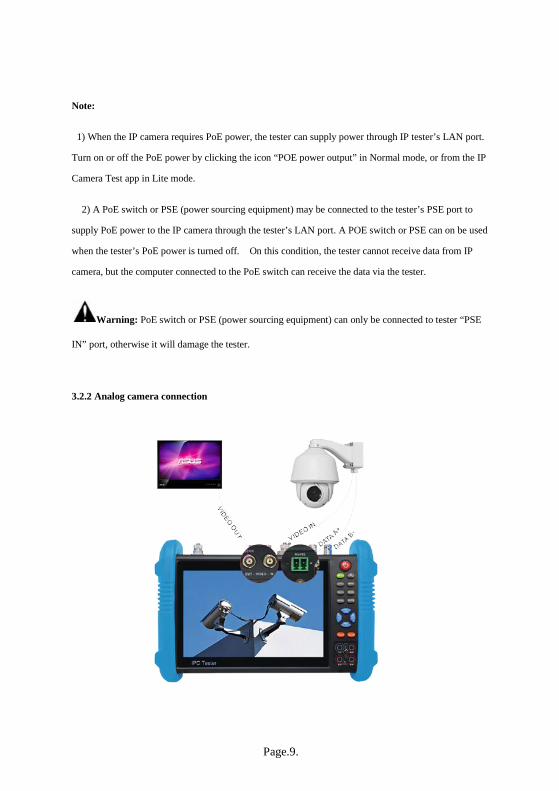
3.2.2 Analog camera connection

Page.10.
(1) Connect the camera's video output to the IP tester’s BNC video input “CVBS IN”. The image will
display on the tester after pushing the CVBS icon.
(2) The tester’s BNC video output “CVBS OUT” may be connected to the CVBS video input of a
monitor (or to a CCTV video balun pair) and the image will be displayed on both tester and monitor.
(3) Connect the camera or the speed dome RS485 controller cable to the tester RS485 interface noting
positive and negative connection of RS485 cable to tester.
3.2.3 HD Coaxial camera connection * SDI, CVI, TVI, AHD camera are classified as HD coaxial cameras. Hereby the following instruction
of how to connect SDI camera to the tester is also applied to CVI, TVI, and AHD camera.
(1) Connect the SDI camera's video output to the IP tester’s “SDI IN” interface and the image will
display on the tester when choosing the “SDI” icon on the tester.
(2) Connect the SDI camera or the speed dome RS485 controller cable to the tester RS485 interface.

Page.11.
3.2.4 HDMI IN
Attach a DVR or other device’s HDMI output to the tester’s “HDMI IN” port and the tester will display
device’s output image.
3.3 OSD menu Press the key 2 seconds to turn on
Press the key again to turn off
Short press the key to enter sleep mode, press it again to test.
If tester works abnormally and cannot be turned off, Press the key several seconds to turn off and
the tester will reset.
3.3.1 Lite mode& Normal mode Lite mode: easily find corresponding apps

Page.12.
In Lite mode, Press the icon several seconds, can move the icon to other apps
In Lite mode, click the finger icon in the lower right corner to release locked icons, move icons,
and change sequence of icons.
Normal mode
To change to Normal mode, choose the “Theme” tab and then press “Desktop style” to toggle
between Normal mode and Lite mode.

Page.13.
In Normal mode, press icon several seconds so icon can be dragged within a page or moved to other
pages.
This allows the user to individualize the tester to specific requirements.

Page.14.
To create New Folder: Drag the icon to the folder in top right corner, enter the folder name. Icon will be
auto placed in the new named folder.
Press the folder several seconds, to change the folder name, you can move the icon out of folder, the
folder will be auto deleted until move out all icons.
Select Icons to enter, if quit, please click
Click “SD card” from “Settings” menu to install or remove SD card.

Page.15.
3.3.2 Drop-down Menu Press and slide at top of screen twice to open shortcut menu. The shortcut menu includes POE power
output, IP settings, HDMI IN, CVBS, LAN info, Settings, etc.
HDMI: Click HDMI to enter the HDMI input mode, where the tester can display a dual test
window (picture in picture) with IP & HDMI inputs or Analog & HDMI inputs.
CVBS: Click icon “CVBS” to enter CVBS input mode where the tester can display both an IP
and analog camera at the same time.
TV OUT: Click “TV out” to enter floating window (picture-in-picture) of the color-bar
generator to send through the BNC/CVBS output to a video monitor for color bar testing of
monitor and cable.
LAN: Display network port or WIFI connection real-time upload and download speeds and other
network parameters.
Settings (Gear icon): Enter settings interface.
IP: Enter IP Settings interface.
POE OUTPUT: Turn on or off the tester’s POE power output to the LAN port.
WLAN: Turn on WLAN net and displays current WLAN status.
Page.16.
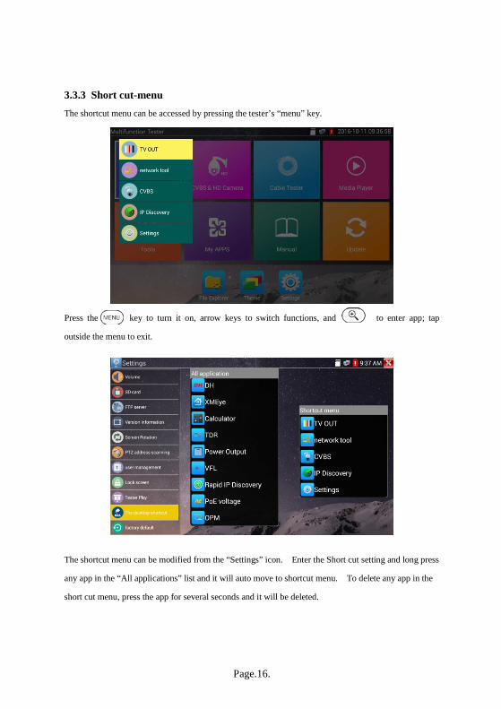
3.3.3 Short cut-menu The shortcut menu can be accessed by pressing the tester’s “menu” key.
Press the key to turn it on, arrow keys to switch functions, and to enter app; tap
outside the menu to exit.
The shortcut menu can be modified from the “Settings” icon. Enter the Short cut setting and long press
any app in the “All applications” list and it will auto move to shortcut menu. To delete any app in the
short cut menu, press the app for several seconds and it will be deleted.

Page.17.
3.3.4 Screen capture Long press the “enter” key to capture screen interface and save it at any time.
You can go “File Explorer” to view documents, pictures, videos and screenshots.
3.3.5 TesterPlay TesterPlay is a mobile screen projection (for android versions only).
The tester creates a WIFI hotspot to connect mobile phone to the tester’s WIFI hotspot, or the
tester and mobile phone connect to the same WIFI network. Tap icon “ ”, then select
“TesterPlay” app to enter where the meter generates two-dimensional code. Scan the code with
mobile phone and download and install the client software. The tester’s screen can be viewed
in real-time projection.

Page.18.
PC screen projection:
Install VLC player in the PC, turn on the VLC player, go to "Media”, “Open Network Streaming",
and input the RTSP address of on the top instrument two-dimensional code, click "play" to view
the screen real-time projection.
Page.19.
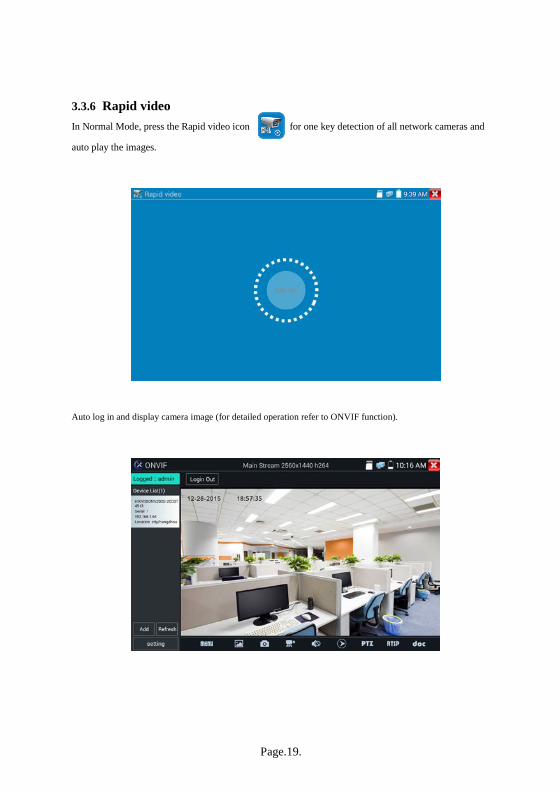
3.3.6 Rapid video In Normal Mode, press the Rapid video icon for one key detection of all network cameras and
auto play the images.
Auto log in and display camera image (for detailed operation refer to ONVIF function).

Page.20.
After entering the ONVIF app, click Refresh to search ip address.
3.3.7 IP discovery Press IP discovery , for tester to auto-scan the whole network segment IP, as well as auto-modify
the tester‘s IP to the same network segment with the scanned camera's IP.
Local IP:Tester’s IP address where the tester can auto-modify the tester‘s IP to the same network
segment with the scanned camera's IP

Page.21.
Discovery IP:Discovers connected equipment’s (usually camera) IP address. If the camera is connected
to the tester directly, tester will display the camera’s IP address; if tester is connected to Local Area
Network, it displays the current IP address.
Temp IIP:after searching IP address, the modified tester’s IP address will not be saved, if you do not
select “Temp IP,” the modified tester’s IP address will auto-save after searching.
Start:To start the PING function click "Start" to PING camera’s IP
Rapid ONVIF: Rapid ONVIF Quick link
IPC TEST: IPC TEST Quick link
Applicability:Using IP discovery app ,you don’t need to know the first two digits of camera’s IP
address , it can auto-scan the whole network segment IP, and auto-modify tester’s IP address , greatly
improved engineering efficiency .
3.3.8 Rapid ONVIF test
Rapid ONVIF can display 4K H.265/H.264 camera image by tester mainstream and one key to activate
Hikvision camera.
Press enter ONVIF function and the tester will auto scan all ONVIF cameras in different
network segments.

Page.22.
The tester lists cameras name and IP address on the left of screen. Tester can auto login camera and
display camera image. Factory default use admin password to auto login, if you modified the password,
then default use the modified password to log in.
If you select ONVIF Rapid mode, the tester will automatically scan different network segments for
ONVIF cameras. It lists the camera name and IP address on the Device List. Tester can auto login
camera and display camera image.
Click the button “Refresh”, tester will scan the ONVIF camera again. Click the newly displayed ONVIF
camera on the “Device List“. The tester will show the IP camera’s relative information and settings.
Activate HIKVISION Camera: When connecting an inactivated HIKVISION Camera, tester can auto
recognized and prompt "The camera is not active, you need to activate it", click "OK" to start
activation .

Page.23.
Enter a new password for the camera
When tester displays “activate success” prompt, click login to display camera image.

Page.24.
Pop-up settings menu when click the “ONVIF” icon in the upper left corner.
Cross network scan: After opening this function, enter “Settings,” “IP Settings” and “Advanced” to
add other network segments IP so “Rapid ONVIF” function can cross network segments to scan
camera’s IP.
Auto Login: After opening this function, tester can auto login camera and display camera image. (The
login password is the same with last time, the first time using password is the default password "admin")
Video streaming transport: UTP and TCP protocol.
View manual: Open Manual.
Restore Defaults: Revert “Rapid ONVIF” to default settings.
OK: Save the modified parameters.
Click the “MENU” icon, at the bottom of the screen, to open camera settings.

Page.25.
While in the live video, the Video Menu is across the bottom of the screen and provides access to the
following tools: Snapshot, Record, Photo, Playback, PTZ, RTSP and docs.

Page.26.
ONVIF PTZ control: Tap the image in the direction you want the PTZ camera to move. For example,
tap the left side of the image to move left, right side to go right, up to go up, and down to go down.
Compatible IP PTZ cameras will rotate accordingly. PTZ rotation direction is displayed on top left
corner of the image.
IP camera video settings: Click “Menu” and click “Video Set” to enter the IP camera’s encoder and
resolution settings. Make the desired changes and click “OK “to save.

Page.27.
Image setting: Click “Imaging Set” to adjust image brightness, saturation, contrast, sharpness and
backlight compensation mode.
Profiles:Click “Profiles" to view video streaming current configuration files, as well as switch between
Major stream and minor stream.

Page.28.
Preview pictures:Quickly preview and zoom in or out pictures; automatic and manual refresh.
Identification: click “Identification” to view camera information.

Page.29.
Time set: click “Time set”, Select "Manual set" to set up the time of camera.
Maintenance: For camera software reset or restore to factory settings.
Page.30.
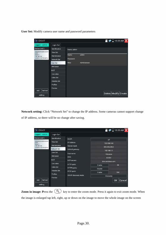
User Set: Modify camera user name and password parameters
Network setting: Click “Network Set” to change the IP address. Some cameras cannot support change
of IP address, so there will be no change after saving.
Zoom in image: Press the key to enter the zoom mode. Press it again to exit zoom mode. When
the image is enlarged tap left, right, up or down on the image to move the whole image on the screen

Page.31.
When the image is enlarged zoom can be also be operated by the keyboard by pressing the key
to zoom in and the key to zoom out; press upward and downward key to move image.
If it is network video input to the tester, as the tester supports resolution up to 1080p, the input image
will be very clear after it is enlarged. This is greatly helpful for the installers to ensure the IP camera’s
video coverage and decide the IP camera’s install site.
Image can only be enlarged in ONVIF mode.
Select relative function on the bottom Toolbar to operate, “Snapshot”, “Record”, “Photos ”,
“Video playback”, “Storage set”, “PTZ control” etc.

Page.32.
Snapshot: Click bottom “snapshot” to screenshot the image and store it to SD card.
If “manual storage” has been set, a dialog box appears with “Input Name” (only one character can be
used as a file name) to save in SD card; if “Auto storage” selected, the tester auto stores the files after
snapshot.
Record: When clicking the bottom “Record” icon, video starts recording. A red recording icon appears
on the screen and begins to flash and a timer appears indicating the time elapsed for the video. Click on
the “Record” icon again to stop recording and save the video file to the SD card.
Playback: Click the “Playback” icon to view saved videos. Double click the video you want to play.
Tap screen to return to the last menu.

Page.33.
To rename or delete video files, click and hold on the file until this screen appears:
Video files can play in the Video player on the main menu.
PTZ
Set preset position: Move the camera to preset position, enter the preset number on the Bottom right
corner to complete position preset.
Call the preset position: Select the preset number on the left, click "Call" to call preset.

Page.34.
PTZ Speed set: Horizontal and Vertical Speed set.
RTSP: Get RTSP address of the current camera
Doc: Auto generate test reports document of camera by clicking "Create documents”. Click Preview to
view the report document.

Page.35.
Enter the camera test information and click "Create Documents" to complete the report.
Click “Doc” menu again to preview the report document.
Icons description: the description of function icons on the bottom toolbar.

Page.36.
3.3.9 IP camera test
Display image from the 4K H.265 camera by mainstream
Click icon to enter IP camera test
Note: Currently, the IPC Test App only supports some brands’ specific IP cameras; these include
specific models made by ACTI, AXIS, Dahua, Hikvision, Samsung, and many more. If the camera is
not fully integrated, then use the ONVIF or RTSP apps.
IPC test interface
Local IP: This is the tester’s IP address. Click “Edit” to enter “IP settings” and change the tester’s IP
address settings.
IP camera type: Click on the IP Camera type to select the Manufacturer and model number of the
integrated IP camera.
Manual:To manually enter camera type click into “IP camera type” field to list Honeywell, Kodak,
Tiandy, Aipu-waton, ACTi, WoshiDA, etc. If the brand is listed, then select camera type, input IP
camera address, username and password, and click “Enter” to enter the camera image display interface.
Page.37.
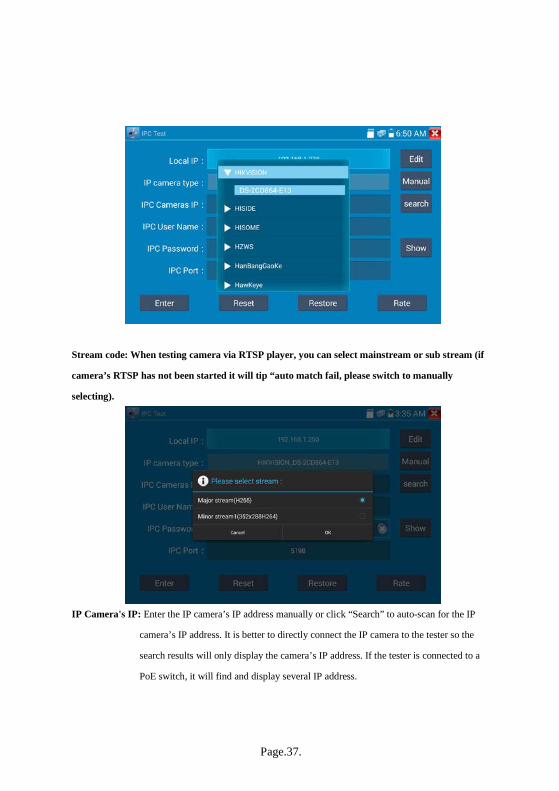
Stream code: When testing camera via RTSP player, you can select mainstream or sub stream (if
camera’s RTSP has not been started it will tip “auto match fail, please switch to manually
selecting).
IP Camera's IP: Enter the IP camera’s IP address manually or click “Search” to auto-scan for the IP
camera’s IP address. It is better to directly connect the IP camera to the tester so the
search results will only display the camera’s IP address. If the tester is connected to a
PoE switch, it will find and display several IP address.
Page.38.
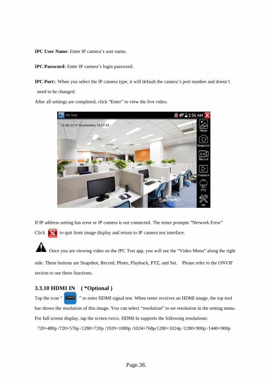
IPC User Name: Enter IP camera’s user name.
IPC Password: Enter IP camera’s login password.
IPC Port:: When you select the IP camera type, it will default the camera’s port number and doesn’t
need to be changed.
After all settings are completed, click “Enter” to view the live video.
If IP address setting has error or IP camera is not connected. The tester prompts “Network Error”
Click to quit from image display and return to IP camera test interface.
Once you are viewing video on the IPC Test app, you will see the “Video Menu” along the right
side. These buttons are Snapshot, Record, Photo, Playback, PTZ, and Set. Please refer to the ONVIF
section to use these functions.
3.3.10 HDMI IN ( *Optional ) Tap the icon “ ” to enter HDMI signal test. When tester receives an HDMI image, the top tool
bar shows the resolution of this image. You can select “resolution” to set resolution in the setting menu.
For full screen display, tap the screen twice. HDMI In supports the following resolutions:
720×480p /720×576p /1280×720p /1920×1080p /1024×768p/1280×1024p /1280×900p /1440×900p

Page.39.
(1) Snapshot
Click the icon “Snapshot,” to take a picture and save the current video frame in the SD card as JPEG
file.
If the unit is set to the manual mode an “Input Name” pop up box will appear and you can enter a title
for the snapshot. If the unit is set up to automatically set file names, this box will not pop up.

Page.40.
(2) Video record
When clicking the “Record” icon, video starts recording. A red recording icon appears on the screen and
begins to flash and a timer appears indicating the time elapsed for the video. Click on the “Record” icon
again to stop recording and save the video file to the SD card
If manual storage was selected, a dialog box will appear asking for “Input Name”; enter a one digit file
name to store in SD card. If auto storage was selected the tester will auto store the files in SD card
after recording.
(3)Photo
Click the icon “photo” icon and click the selected thumbnail photo to display it on the screen. Double
tap the image you want to view to make it full screen. Double-click again to return.
Page.41.
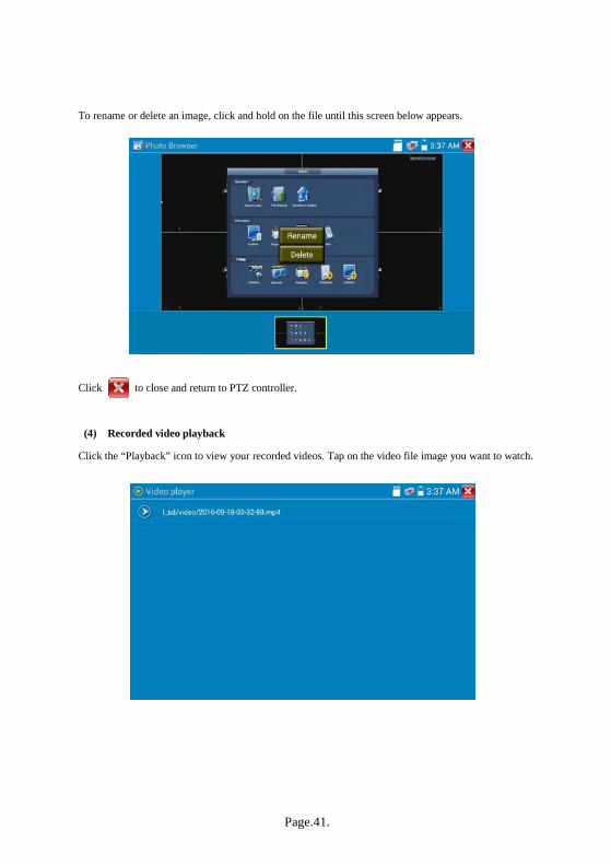
To rename or delete an image, click and hold on the file until this screen below appears.
Click to close and return to PTZ controller.
(4) Recorded video playback
Click the “Playback” icon to view your recorded videos. Tap on the video file image you want to watch.
Page.42.
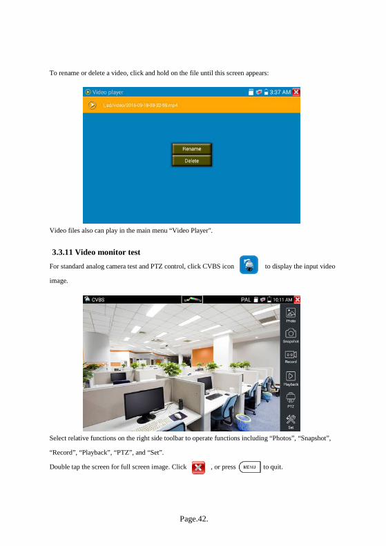
To rename or delete a video, click and hold on the file until this screen appears:
Video files also can play in the main menu “Video Player".
3.3.11 Video monitor test
For standard analog camera test and PTZ control, click CVBS icon to display the input video
image.
Select relative functions on the right side toolbar to operate functions including “Photos”, “Snapshot”,
“Record”, “Playback”, “PTZ”, and “Set”.
Double tap the screen for full screen image. Click , or press to quit.

Page.43.
(1) PTZ controller parameter setting
Select and click icon “PTZ”, to enter PTZ setting:
A. Protocol
Tap or use the up and down arrow keys to move the yellow cursor to the “protocol ” to set the
corresponding protocol. The tester supports more than thirty PTZ protocols, such as PelcoD, Samsung,
Yaan, LiLin, CSR600, Panasonic, Sony-EVI etc.
B. Port
Click “port” to select the communication port for the PTZ camera controlling (RS485, RS422, etc.)
C. Baud Rate
Click “Baud Rate” to select the baud rate according to baud rate of the PTZ camera
(150/300/600/1200/2400/4800/9600/19200/57600/115200).
D. Address: Set the ID according the ID of PTZ camera (0~254). The setting address data must be
consistent the speed dome address.
E. Pan speed: Set the pan speed of PTZ camera (0~63)
F. Tilt speed: Set the tilt speed of PTZ camera (0~63)
G. Set Position (Set Preset)
Click and select “Set Position” to set and save preset position number (1~128),

Page.44.
H. Call Position (Call Preset)
Click and select “Call Preset” to call a saved preset position number (1~128) or to call the dome camera
menu (usually Preset 95).
Check and set the protocols, address, interface and baud, which must be consistent with the dome
camera After setting the parameter, the tester can control the PTZ and lens via the touch screen:
Tap left, right, upward and downward on the touch screen to control the PTZ rotation direction. Use two
fingers moving outward or inward on the screen to zoom in and out the PTZ image.
PTZ key Control:
Press the key control the PTZ direction of rotation
Press the key or , to switch on or turn off the aperture.
Press the key or , adjust the focus manually
Press the key or , manually adjust the zoom
Page.45.
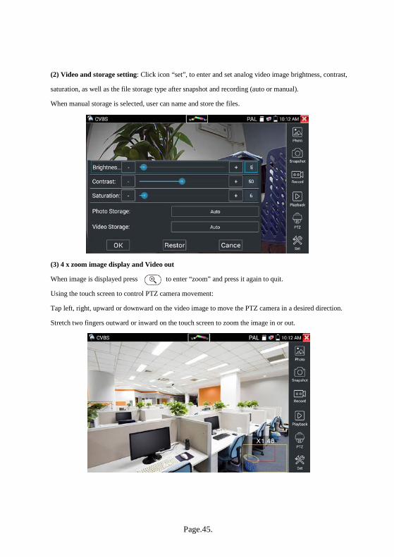
(2) Video and storage setting: Click icon “set”, to enter and set analog video image brightness, contrast,
saturation, as well as the file storage type after snapshot and recording (auto or manual).
When manual storage is selected, user can name and store the files.
(3) 4 x zoom image display and Video out
When image is displayed press to enter “zoom” and press it again to quit.
Using the touch screen to control PTZ camera movement:
Tap left, right, upward or downward on the video image to move the PTZ camera in a desired direction.
Stretch two fingers outward or inward on the touch screen to zoom the image in or out.

Page.46.
If not using touch screen to operate, press the key to zoom out, press the key to
zoom in and press upward and downward keys to move the image
For analog video input resolutions of 720x480 the zoomed image is not clear. For network digital
video input (supporting resolution up to 1280x960), the zoom in image is still very clear.
(4) Snapshot
Click the icon “Snapshot” to save the current video frame in the SD card as JPEG file.
If the unit is set to the manual mode an “Input Name” pop up box will appear and you can enter a title
for the snapshot. If the unit is set up to automatically set file names, this box will not pop up.
(5) Video record
When you click the “Record” icon, a red recording icon appears and begins to flash and a timer appears
indicating the time elapsed for the video. Click on the “Record” icon again to stop recording and save
the video file to the SD card. If the unit is set to manual mode an “Input Name” pop up box will appear
and a two digit title can be entered and saved in SD card. If Auto-storage is selected, the tester will auto
store the files in SD card.

Page.47.
(6)Photo
Click the icon “photo” to enter and click the selected thumbnail photo to display it on the screen.
Double-tap the image you want to view to make it full screen. Double tap again the to return.

Page.48.
To rename or delete an image, click and hold on the file until this screen below appears.
Click to close and return to PTZ controller.
(7) Recorded video playback
Click the “Playback” icon to view your recorded videos. Tap on the video file image you want to watch.

Page.49.
To rename or delete a video, click and hold on the file until this screen appears:
Video files also can play in the main menu “Video Player".
(8) Video level meter (Optional)
Click the icon to enter the video level meter. The IP camera tester has adopted hardware
high-speed sampling and processing technology which can perform both NTSC and PAL video
amplitude signal measurements for PEAK to PEAK, SYNC levels and COLOR BURST Chroma level.
When an analog signal is fed into the meter, the tester displays the measurements on the bottom left
corner of the screen.

Page.50.
While in PAL format, the unit will be mV; while in NTSC format, it will be IRE.
Video signal PEAK to PEAK level:
For NTSC format, the video signal level is 140±15IRE
For PAL format, the video signal level is 1000±200mV
If the level is too low, it will cause the image to lose quality and limit the distance it will travel over
cable. If the level is too high, it will distort the image.
SYNC level: Tests the amplitude of the video sync pulse to verify if the video level is correct.
For NTSC format, the SYNC level is 40 ± 5IRE
For PAL format, the SYNC level is 300 ± 35mV
If the level is too low, it will cause the image to not frame out properly. If the level is too high, it will
lead to a poor quality image.
NTSC
Video signal level 140±15IRE
Chroma level( COLOR BURST) 40±5IRE
SYNC signal level 40±5IRE
PAL
Video signal level 1000±200mV
Chroma level( COLOR BURST) 300±35mV
SYNC signal level 300±35mV

Page.51.
COLOR BURST level: Testing the color burst level will determine if the burst signal is sufficient to
trigger the displays color producing circuit. Burst will diminish in amplitude over longer cable runs and
can get fall below the threshold for the video display to show a color image.
For NTSC format, the Chroma standard level is 40 IRE
For PAL format, the Chroma standard level is 280mV
If the Chroma level is too low, the color will not be as deep, and some details of the image will become
lighter. If the Chroma level is too high, there will be distortions on the image. If the coaxial cable is too
long, it will reduce the Chroma level.
Image loop test:This tests video balun transmitter and receiver and BNC video cable. Connect one end
to the tester “CVBS Out” port and the other end connected to “CVBS In” port, the signal is sent via
“CVBS OUT” port, and received via “CVBS IN” port. If the testing is ok, the tester displays several
gradually dwindling photos on the desktop.
3.3.12 Colour-bar generator (TV OUT) Click to enter the color bar tester to send the color bars out the “CVBS out” port. Click the
“Output format” to select “PAL/NTSC” output.

Page.52.
Click the selected color-bars testing image or single bar (blue or black). Double click to full display on
the screen and output, click to return main menu.
Application
BNC loop test: Tester can send and receive color bar generator through the tester’s “CVBS out” and
“CVBS in” port for testing transmission channels, such as video balun, BNC video cables, etc. Connect
the tester’s “CVBS OUT” port to the balun transmitter’s BNC input port and connect the tester’s
“CVBS IN” port to balun receiver’s BNC output port. The same can be done with a single BNC cable.
A. The tester sends out the color bar by its BNC output to the monitor at the monitoring center. If the
monitor receives the color bar, it means the video transmit channel works normally. On the basis of
the received color bar, the monitoring center can judge if transmission has loss or interference.
B. The tester sends out the pure color bar (such as blue or black color), to test the monitor whether has
bright or black dots
C. The tester sends out video signal image to test if the image received by the monitor has excursion.
Page.53.
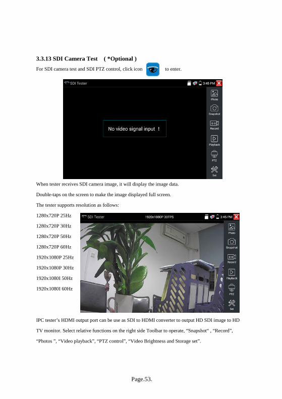
3.3.13 SDI Camera Test ( *Optional ) For SDI camera test and SDI PTZ control, click icon to enter.
When tester receives SDI camera image, it will display the image data.
Double-taps on the screen to make the image displayed full screen.
The tester supports resolution as follows:
1280x720P 25Hz
1280x720P 30Hz
1280x720P 50Hz
1280x720P 60Hz
1920x1080P 25Hz
1920x1080P 30Hz
1920x1080I 50Hz
1920x1080I 60Hz
IPC tester’s HDMI output port can be use as SDI to HDMI converter to output HD SDI image to HD
TV monitor. Select relative functions on the right side Toolbar to operate, “Snapshot“ , “Record”,
“Photos ”, “Video playback”, “PTZ control”, “Video Brightness and Storage set”.

Page.54.
The operation is the same as the video monitor function; refer to the relevant instructions “3.3.11” in the
manual. Click , or press to quit.
3.3.14 CVI camera test ( *Optional ) For HD CVI camera, CVI dome camera test and PTZ control, click icon to enter
With HD CVI signal input, the tester will display the image resolution on the top bar. Double-tap on the
screen to make the image displayed full screen. The tester supports resolution as follows
1280x720P 25FPS / 1280x720P 30FPS / 1280x720P 50FPS / 1280x720P 60FPS / 1920x1080P 25FPS
1920x1080P 30FPS

Page.55.
1.1 Coaxial PTZ control
(1)PTZ control
Click the “PTZ” icon on the right toolbar to do the corresponding setting.
“Port”: select coaxial control (UTC)
Enter PTZ address to perform parameters setting
For operation instructions refer to “3.3.11 Video monitor test”, PTZ (1).
The PTZ address in the tester must be consistent with the dome camera or decoder. After
setting the correct parameters, the tester can control the PTZ and lens.

Page.56.
To control PTZ by screen touch:
Tap left, right, upward and downward on the touch screen to control the PTZ rotation direction; PTZ
cameras will rotate accordingly. With two fingers move outward and inward on the touch screen to
zoom in and out the PTZ.
To control PTZ by key buttons
Press arrow keys to control to control the PTZ direction of
rotation
Press the key , to switch on or turn off the aperture.
Press the key , to adjust the focus manually
Press the key , to manually adjust the zoom
Set preset position
To setup preset position, move the PTZ camera to the preset position and then enter preset position
number. Tap “Set position” to complete and save position number.

Page.57.
Call preset position
Click and select “Call Preset” to call a saved preset position number (1~128) or to call the dome camera
menu (usually Preset 95).

Page.58.
(2)Coaxial (UTC) PTZ camera menu setting
Select “UTC” for the port and select “Menu” for the Coaxitron to enter the dome camera menu.
Enter address of PTZ camera; after finishing the parameter settings, you can press the key or
click the icon to call the dome camera menu.

Page.59.
Press arrow keys to set position.
Tap “close menu” or press the key “ ” key to close camera menu.
(3) For snapshot, record, photo viewer and video playback, please refer to “3.3.11” Video monitor test”

Page.60.
(4) Save setting
Click icon “Set” on the right toolbar to enter storage setting.
Support auto-storage and manual storage.
When select manual storage, user can name and store the files.
1.2 RS485 control
Operation instructions, please refer to “3.3.11 PTZ (1) PTZ control parameters setting”

Page.61.
3.3.15 TVI camera test ( *Optional ) For HD TVI camera, TVI dome camera test and PTZ control, Click icon to enter
With an HD TVI signal input, the tester will display the image resolution on the top bar. Double tap on
the screen to make the image display full screen.
The tester supports resolution as follows:
1280x720P 25FPS / 1280x720P30FPS / 1280x720P 50FPS / 1280x720P 60FPS / 1920x1080P 25FPS
1920x1080P 30FPS / 1920x1080P 50FPS / 1920x1080P 60FPS /2048x1536 18 FPS.
Page.62.
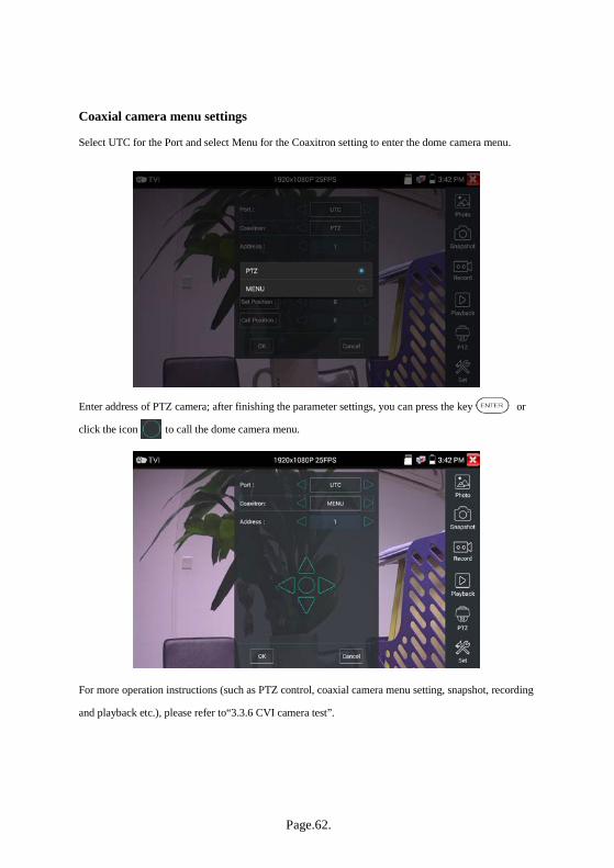
Coaxial camera menu settings
Select UTC for the Port and select Menu for the Coaxitron setting to enter the dome camera menu.
Enter address of PTZ camera; after finishing the parameter settings, you can press the key or
click the icon to call the dome camera menu.
For more operation instructions (such as PTZ control, coaxial camera menu setting, snapshot, recording
and playback etc.), please refer to“3.3.6 CVI camera test”.
Page.63.
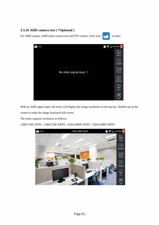
3.3.16 AHD camera test ( *Optional ) For AHD camera, AHD dome camera test and PTZ control, Click icon to enter
With an AHD signal input, the tester will display the image resolution on the top bar. Double tap on the
screen to make the image displayed full screen.
The tester supports resolution as follows:
1280x720P 25FPS / 1280x720P 30FPS / 1920x1080P 25FPS / 1920x1080P 30FPS
Page.64.
(1) Coaxial PTZ control
UTC control: select “PTZ control or PTZ control-2” (AHD cameras have two different controls: if
“PTZ” does not control camera, go “PTZ-2” )
More operation instructions please refer to “3.3.6 CVI camera test”
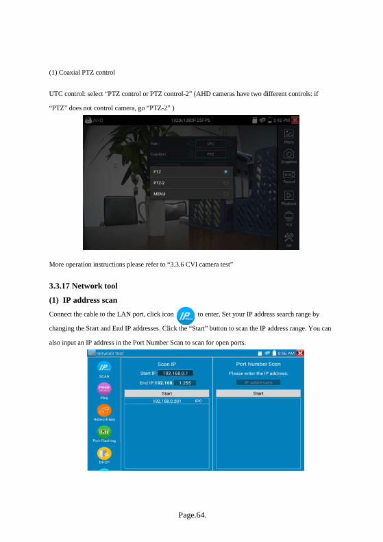
3.3.17 Network tool
(1) IP address scan Connect the cable to the LAN port, click icon to enter, Set your IP address search range by
changing the Start and End IP addresses. Click the “Start” button to scan the IP address range. You can
also input an IP address in the Port Number Scan to scan for open ports.

Page.65.
(2) PING Test To operate the PING Test, connect a network cable to the LAN port and click the icon to open
the PING tool. You can set your LOCAL (native) IP address, Remote IP address (e.g. IP camera),
Packet count, Packet Size, Packet time and Timeout. Press “Start” to start pinging. If the IP camera or
network device is not configured properly or not plugged in, it will say “Destination host unreachable,”
or have 100% packet loss. The send and receive packets will have a 0% packet loss when the tester
connects successfully to the device.
Application: PING testing is the most conventional network debugging tools. It is used for testing if the
connected IP camera or other network equipment’s Ethernet port is working normally and the IP address
is correct.
It’s normal that the first data packet will be lost when test starts.

Page.66.
(3) Network test (Ethernet bandwidth test) Network test (Ethernet bandwidth test)
To use the Network tester, you will need two IP testers. One is used as a Server and the other as a Client.
Both devices must be on the same network segment in order to communicate. Click the icon to
open the Network Tester app.
a). Start the server: Click “Start Server” button to use the first tester as a Server. It will display its IP
address at the top of the screen.
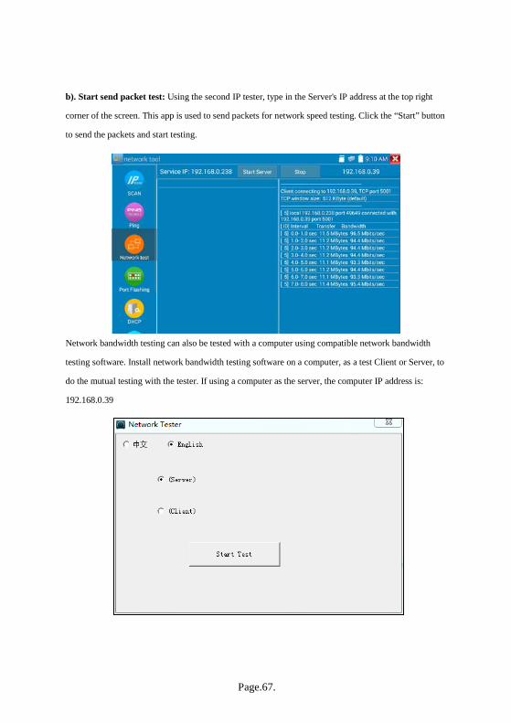
Page.67.
b). Start send packet test: Using the second IP tester, type in the Server's IP address at the top right
corner of the screen. This app is used to send packets for network speed testing. Click the “Start” button
to send the packets and start testing.
Network bandwidth testing can also be tested with a computer using compatible network bandwidth
testing software. Install network bandwidth testing software on a computer, as a test Client or Server, to
do the mutual testing with the tester. If using a computer as the server, the computer IP address is:
192.168.0.39

Page.68.
With the tester as Client, tester’s IP address is:192.168.0.238. The Server and the Client are at the same
network segment, but with different IP address. Input Server’s IP address 192.168.0.39 in the tester and
click “Start” to test network bandwidth.
Or use tester as a Server and the computer as test Client(select Client, input tester’s IP address to test)
Page.69.
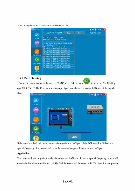
When using the tester as a Server it will show results:
(4)Port Flashing
Connect a network cable to the meter’s “LAN” port; click the icon to open the Port Flashing
app. Click “Start”. The IP tester sends a unique signal to make the connected LAN port of the switch
flash.
If the tester and PoE switch are connected correctly, the LAN port of the POE switch will flash at a
special frequency, if not connected correctly, no any changes will occur on the LAN port.
Application:
The tester will send signals to make the connected LAN port flicker at special frequency, which will
enable the installers to easily and quickly find the connected Ethernet cable. This function can prevent

Page.70.
mistaken connections or disconnections.
(5)DHCP server
Click on the DHCP icon to open the DHCP server app. Select the “Start” check box at the top and
make any desired changes to the network settings. Click “Save” to start assigning dynamic IP
addresses for IP cameras and other networked devices. Click the “Refresh” button to check your Client
list.
Page.71.
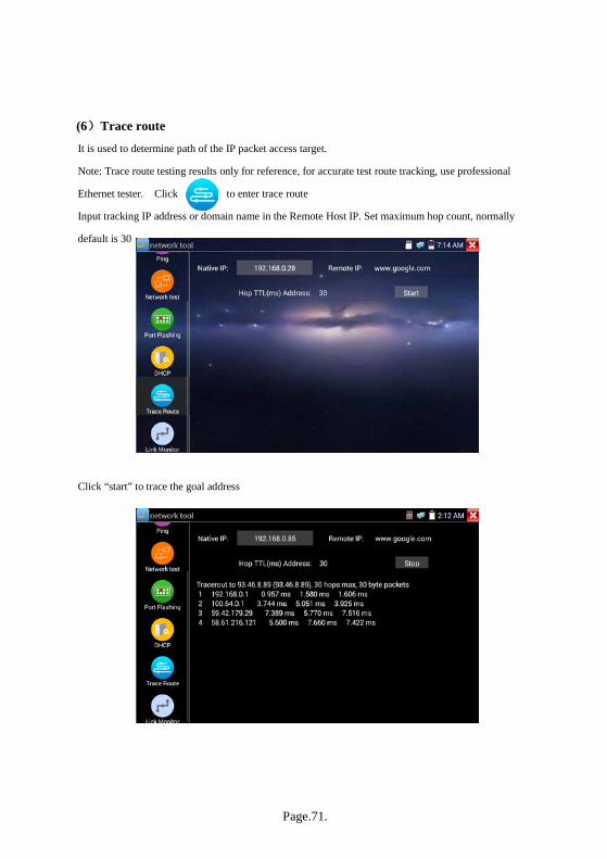
(6)Trace route
It is used to determine path of the IP packet access target.
Note: Trace route testing results only for reference, for accurate test route tracking, use professional
Ethernet tester. Click to enter trace route
Input tracking IP address or domain name in the Remote Host IP. Set maximum hop count, normally
default is 30
Click “start” to trace the goal address

Page.72.
(7)Link monitor
Click the icon to open the Link Monitor app. This app is used to see if an IP address is occupied
by other network devices. This will avoid new address conflicts
Click “Add” and enter the desired IP address. To test different network segments, click the “Settings”
icon on the main menu and go to IP Settings and make the desired changes. Once the desired IP
addresses are added to the Link Monitor list, click “Start”. If the IP address status shows a check mark
the IP address is occupied. If the IP address status shows an X the IP address is available. Click “Stop”
to stop the testing.
Application:
When adding an IP camera or other network device to the current network group, the new IP address
must not be occupied, otherwise it will cause IP conflicts and stop the equipment from operating
normally. Link monitor can check if the new setting IP address is occupied.
3.3.18 Rapid IP Discovery Connect IP equipment to the cable to tester’s LAN port. Press to enter Rapid IP Discovery.
Click “Start” Ping all IP address of connected equipment in the whole network segment.
Click “Stop” to stop finish pinging.

Page.73.
3.3.19 PoE power / DC12V 2A and DC 5V 2A USB power output When the tester is turned on, the 12VDC and 5VDC power output functions are automatically turned on.
If the IP tester is turned off, the 5VDC USB can still be used to power an external USB device.
To use the PoE Power Output function, click on the icon and change the switch “ON” or “OFF”.
The IP camera needs to be connected to the LAN port before you turn PoE Power on. If the IP camera
supports PoE, the PoE power is delivered via pins 1, 2, 3, and 6 on the LAN port. The IP tester will
display “48V ON” at the top of the screen when the POE power is still on.
Note: 1. Do not connect power to the “DC12/2A OUTPUT” port.
2. Do not connect this DC12V/2A power output to the DC12V/IN port of the IP camera tester.

Page.74.
3. The IPC tester power output is close to 2A, if the IP camera requires more than 2A power, the tester
will automatically enter protection mode. Disconnect all the connections to the tester and then
connect the tester with power adaptor to resume testing.
4. Before turning on the PoE power output, make sure the IP camera supports PoE power; otherwise it
may damage the IP camera.
5. Plug in the IP camera to the LAN port prior to turning on PoE power
6. The tester must be at least 80% charged, otherwise the tester will shows “low power” and unable to
supply output power.
3.3.20 Cable Test Click icon to enter
Test LAN cable or telephone cable.
Connect LAN cable or telephone cable to the UTP/SCAN port on the CCTV tester and the cable tester
device provided with the main unit.
The connecting status, cable type and the sequence of wires as well as the serial number of the cable
tester kit will be displayed. The number of the cable tester provided with the tester is 255.

Page.75.
Cable test
The “Diagram of cable sequence” is a reference to determine cable type: crossover or straight-through
twisted pair.
3.3.21 RJ45 cable TDR test Connect cable to tester’s LAN port, click icon “ ” to enter RJ45 cable TDR test app.
Single test: test cable status, length and attenuation.
Repeat test: continue to test cable status, length and attenuation.
Status: after link up, screen will display “online”, “open circuit”, “short circuit” or “cable
sequence error”.

Page.76.
Length: the max test length is 180 meters. When the cable is open circuit or short circuit, tester
can test the cable length; if screen display “online”, the length result may be not accurate.
Cable quality test: Green is good quality cable, Yellow is poor quality cable, red is water poured
cable, while the attenuation will only be displayed when cable over 10 meters.
Advanced Test: tests cable pair status, length, attenuation, reflectivity, impedance, skew, and
other parameters.
Attenuation reflectivity: after link up, if reflectivity value is 0, it is the best quality
communication
Impedance: after link up, if the impedance value is 100 Ω, it is the best quality communication;
the range is generally in 85-135 Ω
Skew: After 1000M link up, when skew value is 0ns, it is the best quality communication; if over
50ns, it will cause a Bit Error Rate in the transmission.
Connection diagram:
Page.77.
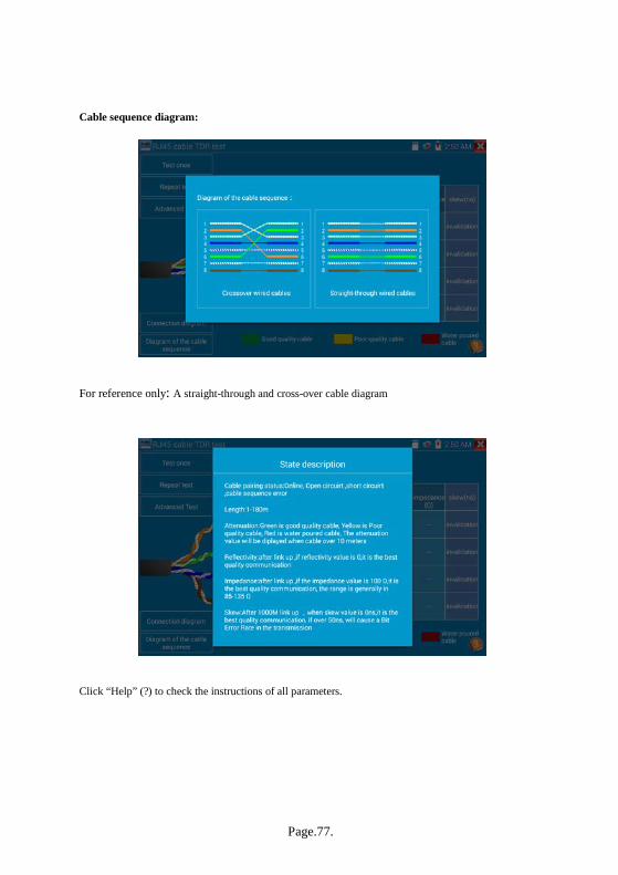
Cable sequence diagram:
For reference only: A straight-through and cross-over cable diagram
Click “Help” (?) to check the instructions of all parameters.

Page.78.
3.3.22 Cable Tracer ( *Optional )
Connect test cable to the UTP port or the BNC cable to the SCAN OUT port on the tester. Click the icon
to enter cable tracer and click the Number on the screen to adjust audio level.
Use the blue Combination cable identifier and network cable tester’s copper pointer to touch all the
cables in the bundle when searching for the other end of the cable. The cable that gives off the loudest
tone is the cable connected to the tester. Press the + or – buttons on your blue cable identifier to adjust
the volume
Note: Install two AAA batteries in your blue Cable Identifier.
Note: While the cable tracer is receiving the audio signal from the tester, it may be induced
into adjacent or crossing cables; however, the cable that makes the loudest noise is the one that is
connected to the meter.
Application
It’s convenient to find out the other end of the cable from the large number of cables in security
maintenance and network engineering. While searching BNC cable, connect one port of the alligator
clips to the copper core or copper net of the BNC cable, the other one to connect the earth wire (barred
windows).
Page.79.
Note: The battery of the cable tracer must be oriented correctly to positive pole + and
negative pole -, otherwise the tester may be damaged.
Note: While the cable tracer tester is receiving the audio signal from the tester, it may be
influenced by other signals and make some noise.
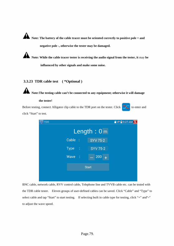
3.3.23 TDR cable test ( *Optional )
Note: The testing cable can’t be connected to any equipment; otherwise it will damage
the tester!
Before testing, connect Alligator clip cable to the TDR port on the tester. Click to enter and
click “Start” to test.
BNC cable, network cable, RVV control cable, Telephone line and TVVB cable etc. can be tested with
the TDR cable tester. Eleven groups of user-defined cables can be saved. Click “Cable” and “Type” to
select cable and tap “Start” to start testing. If selecting built in cable type for testing, click “+” and“-”
to adjust the wave speed.

Page.80.
User-defined calibration: Choose the cable 100 meters to 200 meters (more than 50 meters); click
“Cable” and “Type” to select user-defined 1 for calibration. Eleven groups can be set.
1. Select user-defined and click “Calibration “to enter test, click “user-defined 1” and can define cable
name, such as: AiPu BNC-5.
2. Click “Cable”, “Type” to select cable, and corresponding type, for example, if testing BNC cable,
select “BNC”, if testing communication cable 75-2, select SYV 75-2.

Page.81.
3. Click “+”or “-” to adjust wave speed, while display length is the same as the actual Length. Click
“Save” to save calibration data and then it can be used for the same cable testing next time.
Application: TDR test is the use of the pulse reflection method to transmit pulse signals for testing
cable. When cable is open or short circuit a reflected pulse is generated and the tester receives and
processes the reflected wave and measurement results are displayed on the screen. TDR can test cable
open circuit and short circuit and help engineer quickly find the cable’s problem location.
Note: The TDR reflected signal could be affected by cable quality and connection issues and
to cause the different TDR measurement. The TDR measurement is for reference only.

Page.82.
3.3.24 PoE Voltage test Click icon to enter PoE voltage measurement
Connect a network cable from a PoE switch to the IP tester’s PSE IN port. Connect an IP camera or
other PoE device to IP tester’s LAN port. The PoE voltage and the cable’s pin connection status show
on the screen.
Note: This test if for measuring the voltage being drawn by the PoE device, therefore the
IP tester must be between the PoE switch and the PoE device for test to work.
Note: The PoE switch must be connected to the PSE IN port. The powered device such as IP
camera or other PoE node must be connected to the LAN port.
Note: Do not connect PoE power supply equipment (such as a PoE switch) to the tester’s
UTP/SCAN port; otherwise it will damage the tester.
PSE transmission
When PoE / PSE voltage testing, the tester not only can transmit voltage to supply power for camera,
but also transmits data at the same time, therefore a computer connected to the PSE port can log into the
camera connected to tester’s LAN port.

Page.83.
3.3.25 12V power input test
Connect 12V power adaptor to tester’s charging port, then click icon “PoE” (POE Power Info) to
enter voltage measurement app. The screen will display the current adaptor input voltage and
power. Note: the displayed 12V input power is the battery charging power and the device
working power. The measured power will vary depending on current charging power and
backlight brightness.
Warning: Do not connect a device with input power over 17V to the tester’s “12V IN” port,
otherwise it will damage the tester.
Page.84.
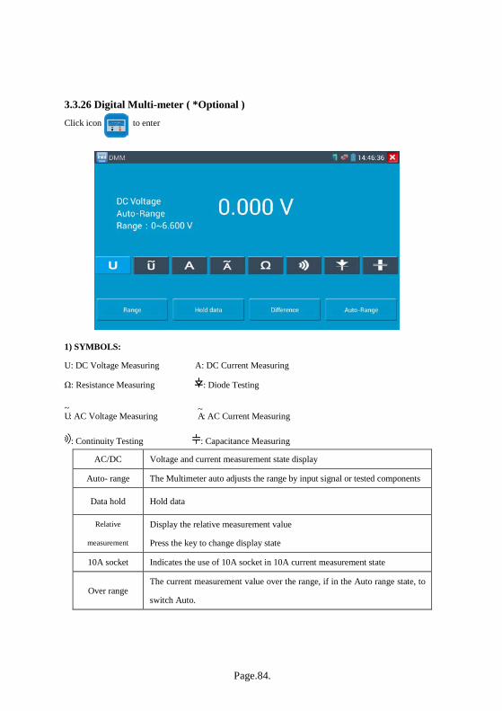
3.3.26 Digital Multi-meter ( *Optional ) Click icon to enter
1) SYMBOLS:
U: DC Voltage Measuring A: DC Current Measuring
Ω: Resistance Measuring : Diode Testing
U~
: AC Voltage Measuring A~
: AC Current Measuring
: Continuity Testing : Capacitance Measuring
AC/DC Voltage and current measurement state display
Auto- range The Multimeter auto adjusts the range by input signal or tested components
Data hold Hold data
Relative
measurement
Display the relative measurement value
Press the key to change display state
10A socket Indicates the use of 10A socket in 10A current measurement state
Over range The current measurement value over the range, if in the Auto range state, to
switch Auto.

Page.85.
2) OPERATING INSTRUCTION
A. DC Voltage Measuring
a. Connect the black test lead to the “COM” jack and the red test lead to the “V/Ω” jack.
b. Select U, to enter the DC voltage measurement.
c. The tester defaults to Auto range status. Click the “DC auto range” key to select manual range or
restore auto range.
Manual range: 0.000V 6.600V range
00.00V 66.00V range
000.0V 660.0V range
000.0mV 660.0mV range
B. AC Voltage Measuring
a. Connect the black test lead to the “COM” jack and the red test lead to the “V/Ω” jack.
b. select U ~ to enter the AC voltage measurement.
c. The tester defaults to Auto range status. Click the “AC auto range” key to select manual range or
restore auto range.
WARNING! The voltage input cannot exceed 660V DC, it’s possible to show higher voltage,
but it’s may destroy the inner circuit.
Be aware of possible electric shock when measuring high voltage.
WARNING! The voltage input cannot exceed 660V A, it’s possible to show higher current, but
it’s may destroy the inner circuit.
Be aware of possible electric shock when measuring high voltage.

Page.86.
Manual range: 0.000V 6.600V range
00.00V 66.00V range
000.0V 660.0V range
000.0mV 660.0mV range
C. DC Current Measuring (manual range only)
a. Connect the black test lead to the “COM” jack and the red test lead to the “mA” jack for a maximum
of 660mA current. For a maximum of 10A, move the red lead to the 10A jack.
b. select A to enter the DC current measurement and the screen will display “DC current ” will read in
manual range;
c. Manual range: 0.000mA 6.6mA range
00.00mA 66.00mA range
000.0mA 660.0mA range
00.00A 10.00A range(use 10A socket)
d. Select the appropriate range to enter current measurement
NOTE:
When “OL” is displayed, it indicates over range situation and the higher range has to be selected.
When the value scale to be measured is unknown beforehand, set the range selector at the highest
position.
The maximum current of mA socket is 660mA; over-current will destroy the fuse and will damage
the meter.
The maximum current of 10A socket is 10A; over-current will destroy the meter and harm the
operator.
WARNING!
Disconnect power to the circuit to be tested before connecting meter to circuit.
Reapply power after meter is connected with the circuit for measurement.

Page.87.
D. AC Current Measuring (Manual range only)
a. Connect the black test lead to the “COM” jack and the red test
lead to the “mA” jack for a maximum of 660mA current. For a
maximum of 10A, move the red lead to the 10A jack.
b. select A~
to enter the AC current measurement and manually
select the range
c. Manual range: 0.000mA 6.600mA range
00.00mA 66.00mA range
000.0mA 660.0mA range
00.00A 10.00A range(use 10A socket)
Note:
When “OL” is displayed, it indicates over range situation and the higher range has to be selected.
When the value scale to be measured is unknown beforehand, set the range selector at the highest
position.
The maximum current of mA socket is 660mA; over-current will destroy the fuse, and will damage
the meter.
The maximum current of 10A socket is 10A; over-current will destroy the meter and may harm the
operator.
Only input alternating current when in “AC” mode.
WARNING!
Disconnect power to the circuit to be tested before connecting meter to circuit.
Reapply power after meter is connected with the circuit for measurement.

Page.88.
E. Resistance Measuring
a. Connect the black test lead to the “COM” jack and the red test lead to the “V/Ω” jack.
b. to select Ω, enter the Ω ohms measurement.
c. the tester defaults to Auto range status. Press the key manually
select range and press “Auto Range” to restore “Auto range”
Manual range: (Connect the red lead to black leads, will display the
measure range)
000.0Ω 660Ω range
0.000 KΩ 6.600KΩ range
00.00 KΩ 66.00KΩ range
000.0 KΩ 660.0KΩ range
0.000 MΩ 6.600MΩ range
00.00 MΩ 66.00MΩ range
F. Continuity Testing
a. Connect the black test lead to the “COM” jack and the red test lead to the “V/Ω” jack.
b. select , enter the continuity test. Connect test leads across
the two points of the circuit under testing.
c. If continuity exists (i.e., resistance less than about 50Ω), a built-in
buzzer will sound.
G. Diode Testing
WARNING!
When measuring in-circuit resistance, be sure the circuit under test has all power removed and that
all capacitors have discharged fully.
WARNING!
When testing the circuit continuity, be sure that the power of the circuit has been shut down and all
capacitors have been discharged fully.

Page.89.
a. Connect the black test lead to the “COM” jack and the red test
lead to the “V/Ω” jack (the red lead being the anode “+”).
b. to select to enter the diode testing.
c. To test forward bias, connect red test lead across to the anode and
the black lead to the cathode of the diode under testing.
d. To test reverse bias, connect test red lead across to the cathode, the black lead to the anode of the
diode under testing.
e .Tested diode forward voltage should read between 0.5 and 0.8 volts Reverse bias should read “OL”
for infinite reading.
H. Capacitance Measuring
a. Connect the black test lead to the “COM” jack
and the red test lead to the “V/Ω” jack.
b. Select “ ” to enter, enter the capacitance measurement.
c. The tester defaults auto range status; choose manual range by pressing upward and downward key,
Auto range by press the key “NEAR”
Manual range: 0.000nF 6.600nF range
00.00nF 66.00nF range
000.0nF 660.0nF range
0.000uF 6.600μF range
00.00uF 66.00μF range
000.0uF 660.0μF range
0.000mF 6.600mF range
00.00mF 66.00mF range
WARNING!
When measuring in-circuit diodes, be sure the circuit under test has all power removed and that all
capacitors have discharged fully.
WARNING!
To avoid electric shock, be sure the
capacitors have been discharged fully before

Page.90.
Note:
a. The capacitance of a capacitor should be tested separately out of the circuit.
b. To avoid electric shock, be sure the capacitors have been discharged fully before measuring the ca
pacitance of a capacitor.
c. While testing the capacitance of a capacitor to
660uF, the Max time will be 6.6 seconds, if the capacitor is leaked or damaged,
the data can’t be read. The tester will be normal after disconnecting the capacitor.
Manual range and Auto range
When testing, click “Range select “to change the value, click “Auto range “to enter Auto
measurement
Data hold
Click “Hold data” to capture the display reading; the data value displays green. Press it again to
quit.
Relative value measurement
Click “Relative” (Difference) to enter relative value measurement. The tester will Auto-save the
data and the new displayed measurement/ relative value is red color. Press it again to quit
The displayed value in yellow is the hold function and the relative value combined.

Page.91.
The meter protection
Voltage protection
Voltage input cannot exceed 660V DC or AC; it’s possible to show higher voltage, but may destroy
the inner circuit.
Resistance, Continuity, Diode, PTC component Protection
Wrong input voltage will automatically enter protection state and only suitable for short and limited
time work. If input voltage over 600V, will damage the meter.
mA current fuse range: 250V 1A
If the current is over the rated range the fuse will blow to protect the meter. Use the same fuse type
and rating when changing the fuse. The fuse can be accessed under the battery cover.
Note: 10A socket is without fuse protection. Using 10A socket for measuring voltage can
damage the meter.
3.3.27 Optical power meter ( *Optional ) Click icon to enter optical power meter and contains five wavelengths (1625nm,1550nm ,
1490nm , 1310nm ,1300nm , 850nm), linear or nonlinear optical power display (both for optical power
testing and Fiber link loss relative measurement ).
Note: Please keep the fiber connector and the dust cap clean with the special alcohol.

Page.92.
Data hold
While testing, click “Hold” to data hold, the data will not change. Press “Hold” again to quit.
Relative power value (optical link loss) measurement While testing, set the wavelength for measurement. Click “relative” (difference) to test, the tester Auto
save current fiber power value as the base reference value. Input another optical fiber to be measured,
the displayed new measurement and relative value is red color. Press it again to quit.
Data hold and Relative measuring use together, the data is yellow while the function is effect.

Page.93.
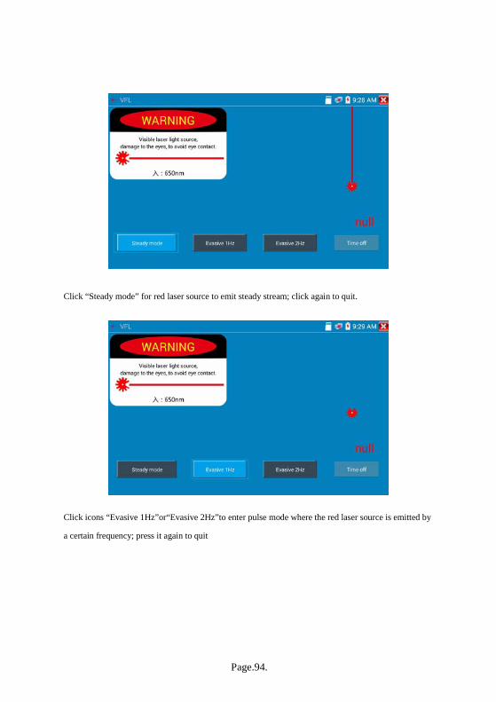
3.3.28 Visual Fault Locator ( *Optional ) Click icon to enter the visual fault locator
VFL contains four status modes: Steady mode”, “Evasive 1Hz”,“Evasive 2Hz”and“Time off”. Click
button “Steady mode” to enter steady status; click button “Evasive 1Hz” and “Evasive 2Hz to enter
pulse mode; click button “Time off” and VFL is turned off for selected time intervals: may select (5
mins, 10 mins, 30 mins, 60 mins and 120 mins).
Page.94.
Click “Steady mode” for red laser source to emit steady stream; click again to quit.
Click icons “Evasive 1Hz”or“Evasive 2Hz”to enter pulse mode where the red laser source is emitted by
a certain frequency; press it again to quit

Page.95.
3.2.29 Audio Record Connect an audio device to the IP tester’s audio input port. Click the icon to enter the Audio
Recorder app. Click the red button to stop and the unit will prompt you to save the recording
3.3.30 Data monitor Click icon to enter data monitor for receiving RS485 data from an RS485 controller.
Click “Setting” to choose the baud rate of RS485; it must be the same as the DVR or the Control
keyboard. The DVR or Control keyboard will send the code to the tester, if it can be read, the protocol
will show on the upper right, such as PelcoD.
While the tester receives the code, press the key to empty.
Though the RS485 port, display the PTZ control code of the multifunctional keyboard or the DVR.
Controller can check the status of the RS485 transmission through the code on the display. (The RS485
communication rate must be the same.)
Application: Check the RS485 communication states of an RS485 control keyboard, joystick or DVR
whether normal. Engineer can analyze the protocol and check the data through the displayed code.

Page.96.
3.3.31 Audio player Click the icon to enter. The audio player only supports MP3 format Audio files.
3.3.32 Media Player Click the icon to enter
The Media player can browse video and image files. It supports the video formats of MP4, H.264,
MPEG4, and MKV. The IP tester’s recorded files can play directly via the Media player. The Media
player will automatically display the video files from the SD card. Click on the desired file to play.
Click RETURN to exit.
To rename or delete an existing file, press the file name for a few seconds until the screen below appears.
You can then rename or delete the file by pressing the desired option.
Page.97.
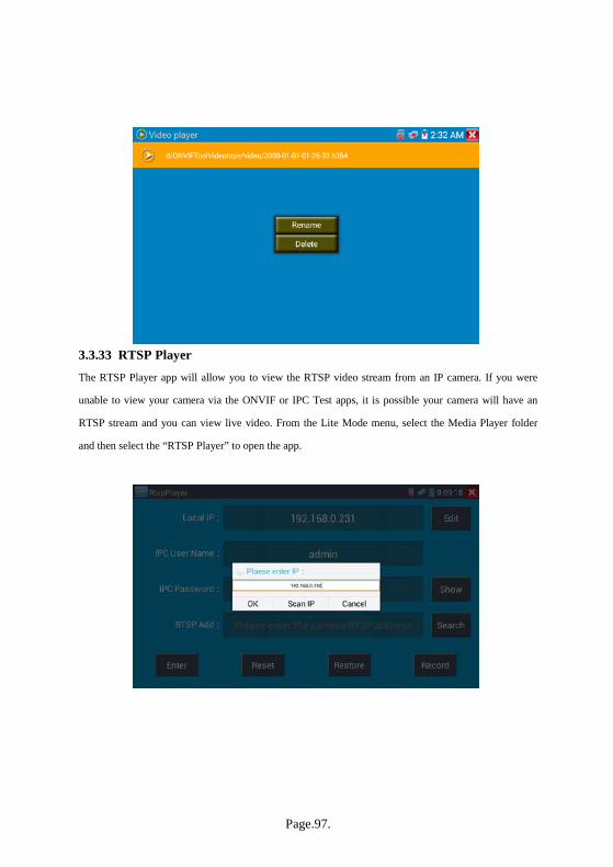
3.3.33 RTSP Player The RTSP Player app will allow you to view the RTSP video stream from an IP camera. If you were
unable to view your camera via the ONVIF or IPC Test apps, it is possible your camera will have an
RTSP stream and you can view live video. From the Lite Mode menu, select the Media Player folder
and then select the “RTSP Player” to open the app.

Page.98.
Local IP: This is the IP testers IP address.
RTSP Add: This is where you can manually enter the IP camera’s RTSP URL or click on Search to to
Scan IP to search the network for cameras that use an RTSP stream. Once found, an IP address will pop
up and clicking on it will allow selection of a stream.
IPC Username: Enter the IP camera’s user name.
IPC Password: Enter the IP camera’s password.
Once you have entered all the necessary information, select Enter at the bottom left to view the RTSP
stream.
Note: in the event the ip tester does not auto detect the rtsp stream, refer to the specific camera
manufacturer for the specific rtsp stream url. you may find this on line with a search of the
camera model number and the word rtsp.
3.3.34 Hik test tool
Hik test tool app is designed for activating and debugging Hikvision cameras; the app can auto-identify
unactivated Hikvision cameras and display an image from the Hikvision camera.

Page.99.
Tap icon to enter
1. Hikvision activation:When connecting the unactivated Hikvision camera to the tester, it will auto
identify and display “Unactivated” in safety mode. Select needed activation by clicking bottom
right corner button “Enable” and then pop-up “the camera is not activate, activate now”?
2. Input password:Input new password and tap “ok” to activate
3. Confirm activation
After activating the camera, the program default modifies the camera IP. It can activate multiple
cameras in the local area Network and pop-up menu to modify IP to improve project efficiency.

Page.100.
Play: display image from the camera
Modify network information: Change the camera IP address, subnet mask and gateway etc.
Modify user information: Modify the camera's user name and password.

Page.101.
Factory Reset:Camera factory reset

Page.102.
3.3.35 Dahua test tool
Dahua test tool is developed for installation and debugging of the Dahua IP camera. It can display
image, modify IP user name and password, etc. Making Dahua camera test more convenient and
quickly. Click “DH” icon , to enter Dahua test tool.
Select the camera from the online detection menu. If the camera supports non-verification login, click
“play” directly and view the image.
From the Pop up stream menu, select mainstream or secondary substream to test.
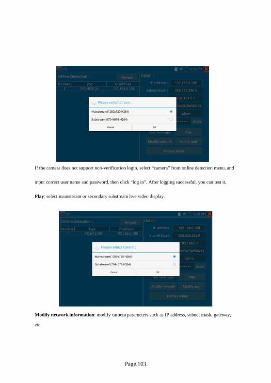
Page.103.
If the camera does not support non-verification login, select “camera” from online detection menu, and
input correct user name and password, then click “log in”. After logging successful, you can test it.
Play: select mainstream or secondary substream live video display.
Modify network information: modify camera parameters such as IP address, subnet mask, gateway,
etc.
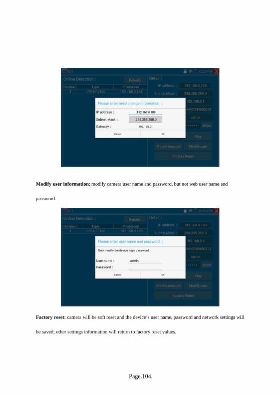
Page.104.
Modify user information: modify camera user name and password, but not web user name and
password.
Factory reset: camera will be soft reset and the device’s user name, password and network settings will
be saved; other settings information will return to factory reset values.

Page.105.
3.3.36 Update
Copy the downloaded update file to SD card "update" directory, if no directory, please create one.
Click the icon to open the Update menu. Select “Local Update” to update via the SD card or
select “Online Update” to check for updates on the internet. If there are applications that need updating,
the applications will be displayed on the screen.

Page.106.
3.3.37 QuickOffice Quick office app (supports Excel, Word, and PowerPoint formats).
3.3.38 LED Flashlight
Click icon to enter the LED Flashlight.
While in the flashlight app, click the red button on the flashlight to turn on the LED lamp. Press it again
to turn it off. If you don’t press the red button to shut off the lamp and press the button to exit the
app, the lamp will stay on. Click the Time Setting button to set a timer that will shut off the lamp.

Page.107.
3.3.39 Browser Click icon to enter the browser.
Type in the camera’s IP address and press “Go” to access the IP camera’s interface.
NOTE: You will not be able to view live video in the web browser. For viewing video live, use the
IP tester‘s live camera view Apps
The IP camera and IP tester must be on the same network segment for the browser to interface with the
camera. If they are not in the same segment, click the “RETURN” button to exit browser and open the
“Settings” app from the main menu to change the IP tester’s network settings to match those of the IP
camera.
3.3.40 Notepad Notepad can be used to note important testing results. Click the “Save” key to save the contents.
Notepad can auto record the storage date and time.
.

Page.108.
Click to view the notepad and all saved contents will display. Click each record bar to show the
details. Press the record bar for several seconds to prompt whether to delete it.
3.3.41 System Setting Click icon to enter System Settings.
Language: Select your desired language: English, Chinese, Korean, Russian, Italian, Polish, Spanish,
French or Japanese.

Page.109.
Typewriting: You can select typewriting or install other typewriting.
Date/Time: Set the Date and Time of the IP tester
IP setting: Manually set the IP address, Subnet Mask, Default Gateway and DNS address or select
“Dynamic allocation” to use DHCP. To test multiple network segments, click “Advanced” and then
click “Add” to enter another IP address for the IP tester.
After setting an advanced IP address (refer to the photos above), the unit can test two network segments
(192.168.5.0) and (192.168.1.0) at once.
WLAN Net: Turn WiFi off or on by pressing the “Open the WiFi” button. Once WiFi is turned on the
tester will scan for wireless networks in your area.

Page.110.
Select and press the desired WiFi Network for several seconds to set static IP address.
Wi-Fi hotspot: input “SSID” name and “password”, and then click “OK” to create Wi-Fi hotspot.

Page.111.
Brightness: Set the desired brightness of the IP tester and adjust the sleep time settings.
Volume: Set volume level
SD Card: Displays SD Card Capacity. You can also format the SD card or unmount it before removing.
FTP server: Once the IP tester connects to a network, a computer can be used to read the SD card files
via FTP Server.
Start the FTP server and then input the tester’s FTP address in the PC’s address bar. This will enable the
PC to read, copy, and edit the files from the SD card without the use of SD card reader.

Page.112.
Version Information: shows tester’s and application’s version information, uninstall any apps by
pressing icon for several seconds.
Screen Rotation: Click on “Screen Rotation” to flip the IP tester’s display 180 degrees. This function is
very convenient for the user to connect the LAN cable on the bottom of the unit without having to flip
the unit itself.
PTZ address scan: Used to toggle on and off PTZ address scanning. This needs to be turned on before
using the PTZ Scan feature of the PTZ controller app.
User Feedback: For any user comments or suggestions for the tester; please connect it to network and
write your feedback.
Lock Screen: You can choose password Lock screen, pattern Lock screen or “NO” to choose whether
or not to lock the screen. The tester’s default is not locked.
Password Lock Screen: Sets password to lock the screen and thereafter requires user to input password
when the meter is in standby mode or turned on.
Pattern Lock Screen: Allows the user to define a pattern to unlock the screen thereafter requiring the
user to draw a pattern to unlock when the meter is in standby mode or turned on.
To modify the locked screen password or pattern, you need input lock password/pattern again, select
“Lock screen” to reset lock screen password or pattern.
Restore Default: Used to restore tester to factory default settings; all your personal files and apps will
be removed.

Page.113.
3.3.42 File explorer The file explorer is located on the bottom of the screen on the tester. After entering the explorer, click
“File” on the top bar tool to view internal or external storage. Click on the upper right corner Icon “...”
and a pop-up menu will appear with other operations or exit.
Browse
Browse includes Music, Videos, Pictures, Documents, zip files, etc.

Page.114.
FTP server
User can choose internal or external SD (see FTP Server in section 3.3.41 for instructions).
3.3.43 Theme
Desktop style: User can select Lite mode or Normal mode.
Theme: Theme is used to change the background color of icons. The user can select up to four colors
which will display on menus in either fixed or random order. When pressing an icon in the lower area
for several seconds, the selected color icon will move to the upper rectangular area; pressing on one of
these icons for several seconds will remove it. User can choose fixed order or random order. Click “set”
to save and change icon colors. Note: icon colors are only changed for the particular mode (Lite or
Normal) the tester is in at the time.

Page.115.
Background Color
When setting the background color, the user select colors from Color Phase and can also input color’s
RGB to set.
After finishing color setting, click “set” to set it as desktop or application background.
Set as desktop background: Setting color as desktop background.
Set as application background: Set color as application background.
Simultaneously Set: Setting color as desktop background and application background.
Cancel: Cancel current setting.

Page.116.
Picture:
Click Picture to select an image temporarily as a background to view setting effect. Click “more” to
select pictures from local file, and click set to set picture as background.
Sliding effect:
Tester’s sliding effect includes stereoscopic effect, fold effect, left and right fold, rotate effect, Ombre
effect, etc.; select one of these effects to view slide effect in the square area, and click “set” to save.

Page.117.
3. 4 Audio test User can test the audio input from audio devices by connecting the device to the IP tester with the
supplied audio cable.
3.5 HDMI output The built in HDMI output port can output live video from an analog or IP camera, recorded files, media
files and images to HDTV monitors. Connect an HDMI cable from the IP tester to an HDTV monitor at
any time. It supports up to 1080P resolution.
3.6 PoE power output The IP tester supports PoE (Power over Ethernet) output to an IP camera via the LAN port. Data
transmission and 48VDC use the network cable’s 1, 2, 3, and 6 pins to deliver power. If the IP camera
supports PoE, user can directly connect to the camera without the use of an external power supply.

Page.118.
Notice
a. Make sure the cable connected to the tester’s LAN port is straight-line cable and has no short circuit,
otherwise will damage the tester.
b. Before using PoE power output, check to make sure the IP camera supports POE power. Otherwise
it will damage the IP camera.
c. The instrument’s PoE maximum power output is 24W. If Ultra- high-power load happens, the tester
will enter protection mode.
3.7 DC 12V 2A power output When the IP tester is turned on, the 12VDC power output ON by default. The smaller end of the
supplied converter cable connects to the tester’s DC12V/2A OUTPUT and the other end connects to the
camera’s power input.
Application
Power output function is mainly used in the camera field for demonstration and testing, meanwhile, for
some camera installation sites, if there is no power outlet for the adapter to power the camera, the tester
can offer temporary power for it. Do not use tester supply power for an extended period.

Page.119.
Notice:
a. Don’t input any power into the “DC12/2A OUTPUT” port of the tester.
b. User damage is not within our company’s warranty.
c. The IP tester’s power output capacity is 2A. If the IP camera uses more than 2A, the tester will
automatically enter a protection mode.
d. Disconnect all cables from the tester and reboot it to resume using the tester.
The IPC tester power output is close to 2A, if the IP camera’s power is over 2A, the tester will
auto enter protection mode. Disconnect all the connections of the tester and then connect the tester
with power adaptor to resume the tester.
e. Make sure the tester has a sufficient charge otherwise the tester will not able to provide enough
output power.
3.8 USB 5V 2A power output When the tester is turned on, the DC 12V and DC 5V power output functions are automatically turned
on. If the IP tester is turned off, the DC 5VUSB can still be used to power an external USB device.
NOTE: The USB port is for power only and not data.

Page.120.
4. Specifications
4.1 General Specifications Model IP Camera Tester【*】models Optional
Display New 7 inch IPS touch screen CCTV tester, 1280x800 resolution
Network port 10/100/1000M auto adjust, RJ45
WIFI Built in WIFI,speeds150M, allows you to connect to a wireless network
and view IP cameras
H.265 Mainstream
test
New hardware decoding,4K,H.265/H.264 camera image display by
mainstream testing
IP discovery auto-scan the whole network segment for cameras IP
Rapid ONVIF search camera quickly, auto log in and display image from the camera,
activate Hikvision camera
Hik test tool Activate Hikvision camera, display image from the camera, modify IP,
user name and password parameters etc.
DH test tool Dahua camera test, modify IP, user name and password parameters etc.
IP camera type
ONVIF,ONVIF PTZ, Dahua IPC-HFW2100P, Hikvision
DS-2CD864-E13, Samsung SNZ-5200, Tiandy TD-NC9200S2, Kodak
IPC120L, Honeywell HICC-2300T, RTSP Viewer
SDI video signal test
* (Optional)
1 channel SDI input(BNC interface, resolution support : 720p
25/30/50/60,1080p 25/30/50/60,1080i 50/60
CVI video signal test
*(Optional)
1 channel CVI input BNC interface, resolution support 720p
25,30,50,60fps/ 1080p 25,30fps
TVI video signal test
(Optional)
1 channel TVI input BNC interface, resolution support 720p
25,30,50,60fps/ 1080p 25,30fps
AHD video signal
test *(Optional)
1 channel AHD input BNC interface, resolution support 720p 25,30fps /
1080p 25,30fps
Analog video test 1 channel BNC Input & 1 channel BNC Output , NTSC/PAL (Auto adapt)

Page.121.
Video level meter PEAK video signal level, SYNC signal level, COLOR BURST Chroma
level measurement for CVBS camera.
Zoom Image Supports Analog and IP camera image zooming & movement
Snapshot, Video
record and playback
Capture current images and record live video as JPG file. Media player
will view photos and playback video
HDMI IN
*(Optional)
HDMI IN,Support 720×480p /720×576p /1280×720p /1920×1080p
/1024×768p/1280×1024p /1280×900p /1440×900p。
HDMI output 1 channel HDMI output, supports up to 1080p
RJ45 cable TDR test RJ45 cable TDR test and cable quality test, to test cable pair status, length,
attenuation reflectivity, impedance, skew and other parameters.
12V/2A power
output Output DC12V/2A power to camera
USB 5V power
output 5V 2A power output only , NO data transfer
PoE power output 48V PoE power output, Max power 24W
Screen management Lite mode and normal model available. Under normal mode, user can
change icons sequence and self-define the number of icons in each page
Theme Self-defined icons, desktop and application interface background, modify
interface sliding effect
drop-down menu PoE power switch ,IP setting, WLAN switch , HDMI IN functions etc.
screen lock, password lock screen or pattern lock
Audio test 1 channel audio signal input and 1 channel audio signal output to connect
headphones
PTZ control SupportRS485 control, Baud 600-115200bps, Compatible with more than
30 protocols such as PELCO-D/P, Samsung, Panasonic, Lilin, Yaan, etc
Color bar generator Output one channel PAL/NTSC color bar video signal for testing monitor
or video cable(red, green ,blue, white and black color ).

Page.122.
UTP Cable tester Test UTP cable connection status and display on the screen. Read the
number on the screen
Data monitor Captures and analyzes the command data from controlling device, also can
send hexadecimal
Network test IP address scan, link scan, and Ping test. Quickly search the for IP
camera’s IP address on your network
Cable tracer*
(Optional) Find a connected cable from a bundle of cables using audio tones
PoE /PSE voltage
test Measures PoE switch voltage and displays pin configuration
Digital Multi-meter
*(Optional)
AC/DC Voltage, AC/DC current, Resistance, Capacitance, Data hold,
Relative measurement, Continuity testing . Testing speed: 3 times/
seconds, Data range -6600~+6600.
Optical power meter
*(Optional)
Calibrated Wavelength(nm) :850/1300/1310/1490/1550/1625nm
Power range(dBm) :-70~+10dBm
Visual fault locator
*(Optional) Test fiber’s bending and breakage ( SM and MM fiber)
TDR cable test
*(Optional)
Cable’s open circuit (Breakpoint) and short circuit measurement(BNC
cable, telephone cable)
POWER
External power
supply DC 12V 2A
Battery Built-in 7.4V Lithium polymer battery, 5400mAh
Rechargeable After charging 5~6 hours, normal working time is10hours
Parameter
Operation setting Capacitive touch screen, OSD menu, select your desired language:
English, Chinese, Korean, Russian, Italian or Polish, etc.
Auto off 1-30 (mins)

Page.123.
General
Working
Temperature -10℃---+50℃
Working Humidity 30%-90%
Dimension/Weight 240mm x 154mm x 46mm / 620g
4.2 Multi-meter specifications Counts:-6600~+6600
Conversion rate: 3times/s
Current modes for clamp meter with ZERO function
Isolation: the Multi-meter connector must be isolated with the other connector.
DC voltage
Range Accuracy Resolution
660mV (Manual range)
±(0.3%+4)
0.1mV
6.600V 1mV
66.00V 10mV
660.0V 100mV
AC voltage
Range Accuracy Resolution
660.0mV (Manual range) ±(1.5%+6) 0.1mV
6.600V
±(0.8%+6)
1mV
66.00V 10mV
660.0V 100mV

Page.124.
DC current
Range Accuracy Resolution
6.600mA
±(0.5%+3)
1uA
66.00mA 10uA
660.0mA 100uA
10.00A ±(1%+5) 10mA
AC current
Range Accuracy Resolution
6.600mA
±(0.5%+3)
1uA
66.00mA 10uA
660.0mA 100uA
10.00A ±(1%+5) 10mA
Resistance
Range Accuracy Resolution
660.0Ω ±(0.8%+5) 0.1Ω
6.600KΩ
±(0.8%+2)
1Ω
66.00KΩ 10Ω
660.0KΩ 100Ω
6.600MΩ 1KΩ
66MΩ ±(1.2%+5) 10KΩ
Continuity
Range Resolution Function
660.0Ω 0.1Ω The measurement value less 30Ω±3Ω,the tester will
sound

Page.125.
Diode
Range Resolution Function
2.0V
1mV
Schottky diode:0.15~0.25V
rectifier diode:0.6~1.0V
triode PN junction:0.5~0.8V
Capacitance
Range Accuracy Resolution
6.600nF ±(0.5%+20) 1pF
66.00nF
±(3.5%+8)
10pF
660.0nF 100pF
6.600μF 1nF
66.00μF 10nF
660.0μF
±(5%+8)
100nF
6.600mF 1μF
66.00mF 10μF
4.3 Optical power meter specifications
Measure Range(dBm) -70~+10dBm
Wavelength(nm) 850nm,1300nm,1310nm,1490nm,1550nm,1625nm
Detector InGaAs
Uncertainly
<±3%dB(-10dBm,22℃)
<±5%dB(full range,22℃)
Display Resolution Linear:0.1% ; Nonlinear:0.01dBm
Operating Temperature(℃) -10~+50
Storage Temperature (℃) -20~+70
Connector type FC/PC

Page.126.
4.4 Visual fault locator specifications Laser type LD
Wavelength Calibration 650nm
Output power 5mW(Optional 10mW,20mW)
Modulation mode CW/1Hz/2Hz
Measurement Range 5KM(Optional 10-20KM)
Connector FC/PC exchangeable
Working Temperature -10℃~+50℃
Operating Temperature -20℃~+70℃
The data above is for reference only and any changes will not be informed in advance. For more detailed
technical inquiries, please feel free to call the Technical Department.

Page.127.