IP Addressing & Subnetting · IP Addressing & Subnetting Million Aregawi. What is an IP Address?...
52
IP Addressing & Subnetting Million Aregawi
Transcript of IP Addressing & Subnetting · IP Addressing & Subnetting Million Aregawi. What is an IP Address?...

IP Addressing & Subnetting
Million Aregawi

What is an IP Address?
• An IP address is a unique global address for a network interface
• An IP address:
- is a 32 bit long identifier
- encodes a network number (network prefix)
and a host number
Internet Assigned Numbers Authority (IANA)

IP Addresses (cont.)
• 32 bits in length (IPv4)
• 64 bits in length (IPv6)
• Addresses are divided into a prefix and suffix
• The suffix is the host address
• The prefix is the network number

IP Address Format - Dotted Decimal
• IP addresses are generally read in dotted decimal format.
• 0.0.0.0 through 255.255.255.255
• Much better than reading:
10000001 00110100 00000110 00000000

Dotted Decimal Notation
• IP addresses are written in a so-called dotted decimal notation
• Each byte is identified by a decimal number in the range [0..255]:
• Example:
1000111110000000 10001001 100100001st Byte
= 128
2nd Byte
= 143
3rd Byte
= 137
4th Byte
= 144
128.143.137.144

The old way – Classful IP Addressing
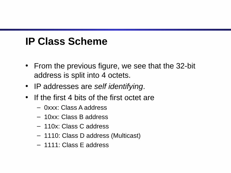
IP Class Scheme
• From the previous figure, we see that the 32-bit address is split into 4 octets.
• IP addresses are self identifying.
• If the first 4 bits of the first octet are– 0xxx: Class A address
– 10xx: Class B address
– 110x: Class C address
– 1110: Class D address (Multicast)
– 1111: Class E address

Dotted Decimal with Classes
• Class A: – 1 prefix octet (128 networks)
– 3 suffix octets (16777216 hosts)
• Class B: – 2 prefix octets (16384 networks)
– 2 suffix octets (65536 hosts)
• Class C:– 3 prefix octets (2097152 networks)
– 1 suffix octet (256 hosts)

Address Space

Class A Addresses
• Class A IP addresses use the 1st 8 bits (1st Octet) to designate the Network address.
• The 1st bit which is always a 0, is used to indicate the address as a Class A address & the remaining 7 bits are used to designate the Network.
• The other 3 octets contain the Host address.

Class A Addresses (Cont.)
• There are 128 Class A Network Addresses, but because addresses with all zeros aren’t used & address 127 is a special purpose address, 126 Class A Networks are available.

Class A Addresses (Cont.)
• There are 16,777,214 Host addresses available in a Class A address.
• Rather than remembering this number exactly, you can use the following formula to compute the number of hosts available in any of the class addresses, where “n” represents the number of bits in the host portion:
(2n – 2) = Number of available hosts

Class A Addresses (Cont.)
• For a Class A network, there are:224 – 2 or 16,777,214 hosts.
• Half of all IP addresses are Class A addresses.
• You can use the same formula to determine the number of Networks in an address class.
• Eg., a Class A address uses 7 bits to designate the network, so (27 – 2) = 126 or there can be 126 Class A Networks.

Class B IP Addresses
• Class B addresses use the 1st 16 bits (two octets) for the Network address.
• The last 2 octets are used for the Host address.
• The 1st 2 bit, which are always 10, designate the address as a Class B address & 14 bits are used to designate the Network. This leaves 16 bits (two octets) to designate the Hosts.

Class B IP Addresses (Cont.)
• So how many Class B Networks can there be?
• Using our formula, (214 – 2), there can be 16,382 Class B Networks & each Network can have (216 – 2) Hosts, or 65,534 Hosts.
Class C IP Addresses
• Class C addresses use the 1st 24 bits (three octets) for the Network address & only the last octet for Host addresses.the 1st 3 bits of all class C addresses are set to 110, leaving 21 bits for the Network address, which means there can be 2,097,150 (221 – 2) Class C Networks, but only 254 (28 – 2) Hosts per Network.

Class C IP Addresses (Cont.)

Special Addresses
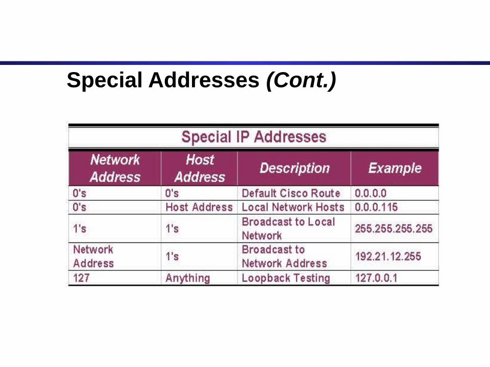
• A few addresses are set aside for specific purposes.
• Network addresses that are all binary zeros, all binary ones & Network addresses beginning with 127 are special Network addresses.
Special Addresses (Cont.)

Special Addresses (Cont.)
• Within each address class is a set of addresses that are set aside for use in local networks sitting behind a firewall or NAT (Network Address Translation) device or Networks not connected to the Internet.

Special Addresses (Cont.)
• A list of these addresses for each IP address class:

Address Delegation
• A central authority exists for IP address delegation.
• In the US, it’s ARIN – American Registry for Internet Numbers (http://www.arin.net)
• People just can’t arbitrarily use any IP network if their network is publicly accessible! That would lead to routing conflicts.

Address Delegation (cont.)
• RFC 1597 – Private networks
– 10.0.0.0 – 10.255.255.255 (Full Class A)
– 172.16.0.0 – 172.31.255.255 (16 Class B’s)
– 192.168.0.0 – 192.168.255.255 (Full Class B)

Special Addresses
• Network address
– Host 0 address for specific class type
– 16.0.0.0 is the network address for the Class A prefix of 16.
– 130.111.0.0 is the network address for the Class B prefix of 130.111.

Special Addresses (cont.)
• Directed Broadcast Address (Network Broadcast Address)
– A network suffix of all 1’s.
– 16.255.255.255 is the directed broadcast address for the Class A prefix of 16.
– 130.111.255.255

Special Addresses (cont.)
• Limited Broadcast Address
– All 1’s in the entire address.
– Limited broadcast address is restricted to the local subnet.
– 255.255.255.255
Special Addresses (cont.)
• Loopback addresses
– Loopbacks are used for testing. An IP looback is application-level testing.
– Any information sent to the loopback address is never passed to the network segment. It is handled internally in the TCP/IP stack.
– 127.x.x.x

Special Addresses (cont.)
• This computer’s address
– If a computer doesn’t know what it’s own address is, but needs to communicate to another machine, it designates the address of 0.0.0.0 for itself.
– Applications include DHCP, BOOTP

• The network prefix identifies a network and the host number identifies a specific host (actually, interface on the network).
• How do we know how long the network prefix is?
– The network prefix is implicitly defined (see class-based addressing)
– The network prefix is indicated by a netmask.
Network prefix and Host number
network prefixnetwork prefix host numberhost number

• Example: ellington.cs.virginia.edu
• Network id is: 128.143.0.0• Host number is: 137.144• Network mask is: 255.255.0.0 or ffff0000
• Prefix notation: 128.143.137.144/16» Network prefix is 16 bits long
Example
128.143128.143 137.144137.144

Classful IP Addressing
Dotted-Decimal Notation
32 bits

• 0.0.0.0: default route, used only during Startup(0.0.0.1 – 0.255.255.254)
• 127.0.0.0: loopback, test TCP/IP for IPC on local machine(127.0.0.1 – 127.0.255.254)
• host all 0: this host
• host all 1: limited broadcast (local net)
Special Purpose IP addresses

27-2 = 126 networks224-2 = 16,777,214 hosts / network
214 = 16,384 networks216-2 = 65,534 hosts / network
221 = 2,097,152 networks28-2 = 254 hosts / network
/8
/16
/24
Class D: (IP Multicasting)
1110
0 4
Class E: (Experimental use)
1111
0 4

Class A Class B Class C D
IP Address Space
E
50 % 25% 12.5% 6.25%
232 = 4,294,967,296 addresses
Partition of the Classful IP Addresses

Limitations to Classful Addressing
• Running out of address space soon 232 = 4,294,967,296 addresses
• Class boundaries did not foster efficient allocation of address space
Lack of address class to support medium size company
-- Class B: 65534 hosts/network, too big! -- Class C: 254 hosts/network, too small! -- Use multiple class C addresses, increase routing table!

Subnetting
Subnetting
• Problem: Organizations have multiple networks which are independently managed – Solution 1: Allocate one or
more addresses for each network
• Difficult to manage• From the outside of the
organization, each network must be addressable.
– Solution 2: Add another level of hierarchy to the IP addressing structure
University NetworkUniversity Network
Medical School
Library
EngineeringSchool

Basic Idea of Subnetting
• Split the host number portion of an IP address into a subnet number and a (smaller) host number.
• Result is a 3-layer hierarchy
• Then: • Subnets can be freely assigned within the organization• Internally, subnets are treated as separate networks• Subnet structure is not visible outside the organization
network prefixnetwork prefix host numberhost number
subnet numbersubnet numbernetwork prefixnetwork prefix host numberhost number
extended network prefix

• Each layer-2 network (Ethernet segment, FDDI segment) is allocated a subnet address.
1 2 8 . 1 4 3 . 1 7 . 0 / 2 4
1 2 8 . 1 4 3 . 7 1 . 0 / 2 4
1 2 8 . 1 4 3 . 7 . 0 / 2 4
1 2 8 . 1 4 3 . 1 6 . 0 / 2 4
1 2 8 . 1 4 3 . 8 . 0 / 2 4
1 2 8 . 1 4 3 . 2 2 . 0 / 2 4
1 2 8 . 1 4 3 . 1 3 6 . 0 / 2 4
Typical Addressing Plan for an Organization that uses subnetting
128.143.0.0/16

Advantages of Subnetting
• With subnetting, IP addresses use a 3-layer hierarchy:» Network
» Subnet» Host
• Improves efficiency of IP addresses by not consuming an entire address space for each physical network.
• Reduces router complexity. Since external routers do not know about subnetting, the complexity of routing tables at external routers is reduced.
• Note: Length of the subnet mask need not be identical at all subnetworks.

CIDR - Classless Interdomain Routing
• Goals:
– Restructure IP address assignments to increase efficiency
– Hierarchical routing aggregation to minimize route table entries
Key Concept: The length of the network id (prefix) in the IP addresses is kept arbitrary
• Consequence: Routers advertise the IP address and the length of the prefix

CIDR Example
• CIDR notation of a network address:
192.0.2.0/18
• "18" says that the first 18 bits are the network part of the address (and 14 bits are available for specific host addresses)
• The network part is called the prefix
• Assume that a site requires a network address with 1000 addresses
• With CIDR, the network is assigned a continuous block of 1024 addresses with a 22-bit long prefix

CIDR: Prefix Size vs. Host Space
CIDR Block Prefix # of Host Addresses /27 32 hosts
/26 64 hosts
/25 128 hosts
/24 256 hosts
/23 512 hosts
/22 1,024 hosts
/21 2,048 hosts
/20 4,096 hosts
/19 8,192 hosts
/18 16,384 hosts
/17 32,768 hosts
/16 65,536 hosts
/15 131,072 hosts
/14 262,144 hosts
/13 524,288 hosts
CIDR and Address assignments
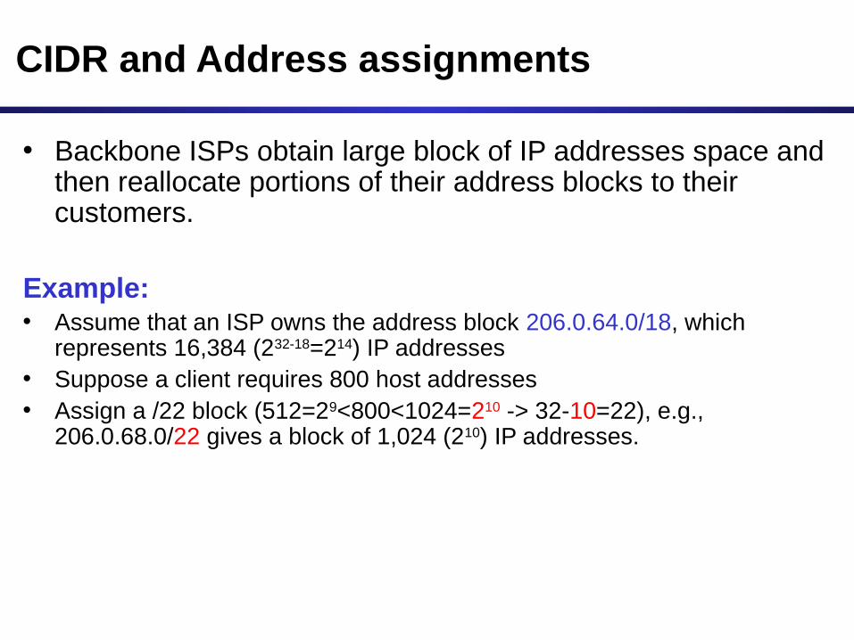
• Backbone ISPs obtain large block of IP addresses space and then reallocate portions of their address blocks to their customers.
Example: • Assume that an ISP owns the address block 206.0.64.0/18, which
represents 16,384 (232-18=214) IP addresses • Suppose a client requires 800 host addresses• Assign a /22 block (512=29<800<1024=210 -> 32-10=22), e.g.,
206.0.68.0/22 gives a block of 1,024 (210) IP addresses.

CIDR and Routing Information
206.0.64.0/18204.188.0.0/15209.88.232.0/21
Internet Backbone
ISP X owns:
Company X :
206.0.68.0/22
ISP y :
209.88.237.0/24
Organization z1 :
209.88.237.192/26
Organization z2 :
209.88.237.0/26

CIDR and Routing Information
206.0.64.0/18204.188.0.0/15209.88.232.0/21
Internet Backbone
ISP X owns:
Company X :
206.0.68.0/22
ISP y :
209.88.237.0/24
Organization z1 :
209.88.237.192/26
Organization z2 :
209.88.237.0/26
Backbone sends everything which matches the prefixes 206.0.64.0/18, 204.188.0.0/15, 209.88.232.0/21 to ISP X.
ISP X sends everything which matches the prefix: 206.0.68.0/22 to Company X,209.88.237.0/24 to ISP y
Backbone routers do not know anything about Company X, ISP Y, or Organizations z1, z2.
ISP X does not know about Organizations z1, z2.
ISP y sends everything which matches the prefix: 209.88.237.192/26 to Organizations z1 209.88.237.0/26 to Organizations z2

CIDR and Routing
• Aggregation of routing table entries:
– 128.143.0.0/16 and 128.142.0.0/16 are represented as 128.142.0.0/15
• Longest prefix match: Routing table lookup finds the routing entry that matches the longest prefix
What is the outgoing interface for
128.143.137.0 ?
Prefix Interface
128.143.128.0/17 interface #1
128.128.0.0/9 interface #2
128.0.0.0/4 interface #5
Routing table

IPv6 - IP Version 6
• IP Version 6
– Is the successor to the currently used IPv4
– Specification completed in 1994
– Makes improvements to IPv4 (no revolutionary changes)
• One (not the only !) feature of IPv6 is a significant increase in size of the IP address to 128 bits (16 bytes)
• IPv6 will solve – for the foreseeable future – the problems with IP addressing
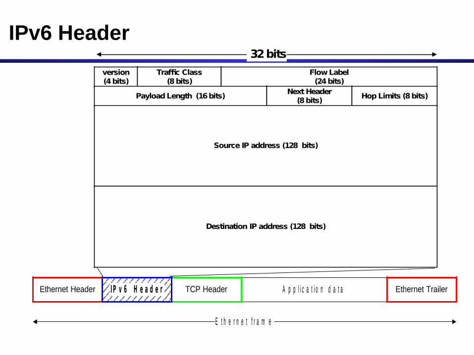
IPv6 Header
A p p l i c a t i o n d a t aTCP HeaderEthernet Header Ethernet Trailer
E t h e r n e t f r a m e
I P v 6 H e a d e r
version(4 bits)
Traffic Class(8 bits)
Flow Label(24 bits)
Payload Length (16 bits)Next Header
(8 bits)Hop Limits (8 bits)
Source IP address (128 bits)
32 bits
Destination IP address (128 bits)

IPv6 vs. IPv4: Address Comparison
• IPv4 has a maximum of
232 4 billion addresses
• IPv6 has a maximum of
2128 = (232)4 4 billion x 4 billion x 4 billion x 4 billion addresses

Notation of IPv6 addresses
• Convention: The 128-bit IPv6 address is written as eight 16-bit integers (using hexadecimal digits for each integer)
CEDF:BP76:3245:4464:FACE:2E50:3025:DF12
• Short notation:• Abbreviations of leading zeroes:
CEDF:BP76:0000:0000:009E:0000:3025:DF12 CEDF:BP76:0:0:9E :0:3025:DF12
• “:0000:0000” can be written as “::”CEDF:BP76:0:0:FACE:0:3025:DF12 CEDF:BP76::FACE:0:3025:DF12
• IPv6 addresses derived from IPv4 addresses have 96 leading zero bits. Convention allows to use IPv4 notation for the last 32 bits.::80:8F:89:90 ::128.143.137.144
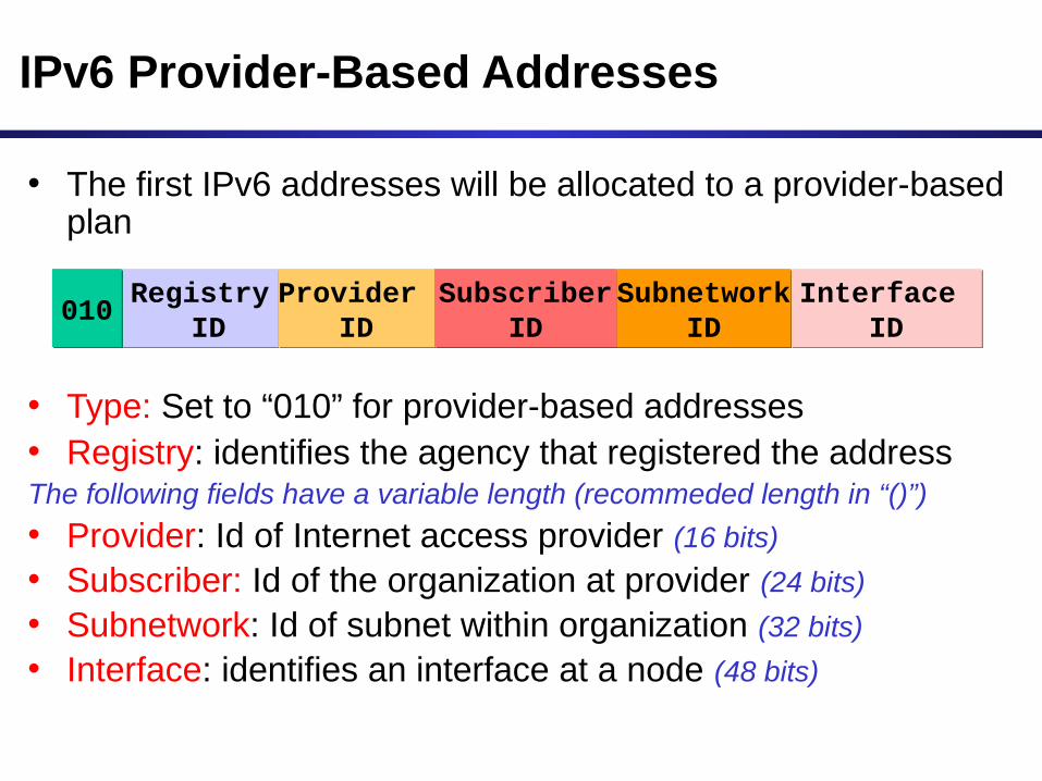
IPv6 Provider-Based Addresses
• The first IPv6 addresses will be allocated to a provider-based plan
• Type: Set to “010” for provider-based addresses• Registry: identifies the agency that registered the addressThe following fields have a variable length (recommeded length in “()”)
• Provider: Id of Internet access provider (16 bits)
• Subscriber: Id of the organization at provider (24 bits)
• Subnetwork: Id of subnet within organization (32 bits)
• Interface: identifies an interface at a node (48 bits)
Registry ID
Registry ID
Provider ID
Provider ID010010 Subscriber
ID Subscriber
IDInterface
IDInterface
IDSubnetwork
IDSubnetwork
ID

More on IPv6 Addresses
• The provider-based addresses have a similar flavor as CIDR addresses
• IPv6 provides address formats for:
– Unicast – identifies a single interface
– Multicast – identifies a group. Datagrams sent to a multicast address are sent to all members of the group
– Anycast – identifies a group. Datagrams sent to an anycast address are sent to one of the members in the group.