Ionosphere Explorer (Explorer XX) Press Kit
23
NATIONAL AERONAUTICS AND SPACE ADMINISTRATION TELS WO 2-4155 WASHINGTON, DC 20546 WO 3-6925 FOR RELEASE: MONDAY AM s August 24 , 1964 RELEASE N O : 64-207 PROJECT: Ionosphere Explorer Satellite DATE: No earlier thlan Aui-. 25, .<< CONTENTS Title S 1GENERALNEWS RELEASE .. fI TECHNICAL INFORMATION .......... Satellite Structure . . . ...... .. Orbit . . . . . . . . . . . . . . . . It The Ionosphere .... . . ..... 5 Scientific Objectives ........ 7 Scout Launch Vehicle . . ...... 1.0 First Stage ...... ..... 11 Second Stage . . .... . . . . 11 Third Stage . . . . .... . . . -l Fourth Stare.e ..... . . . . . 11 . Flight Sequence ...... .... . 11 Tracking & Data Acquisition ..... 12 Ionosphere Explorer Team . . . . . . L III. FACT SIEET ~ Lauc h Pha se . . . . . . . . . . . . 1 J.-1 e'rical Power . . . . . . . . . . . Soundi-xnr. Eerinment. .. . . ..... .. Io.i Mass Soc-trometcr :..perimen .1 I0.1li~ -- re . . . 1 . i . . 16 L- .i-. .'. . . . . . 1 3 Telemetury . . . . . . . . . . . . . .. T le.cy c: Trackin- S'tat ons . . . . :z . ILLUSTRATIONS
-
Upload
bob-andrepont -
Category
Documents
-
view
244 -
download
0
Transcript of Ionosphere Explorer (Explorer XX) Press Kit
8/7/2019 Ionosphere Explorer (Explorer XX) Press Kit
http://slidepdf.com/reader/full/ionosphere-explorer-explorer-xx-press-kit 1/22
NATIONAL AERONAUTICS AND SPACE ADMINISTRATION TELS WO 2-4155
WASHINGTON, DC 20546 WO 3-6925
FOR RELEASE: MONDAY AM s
August 24, 1964
RELEASE NO: 64-207
PROJECT: Ionosphere Explorer
Satellite
DATE: No earlier thlan Aui-. 25, .<<
CONTENTSTitle
S 1GENERALNEWS RELEASE ..
fI TECHNICAL INFORMATION ..........Satellite Structure . . . . . . . . ...
Orbit . . . . . . . . . . . . . . . . ItThe Ionosphere . . . . . . . . . . . 5
Scientific Objectives . . . . . . . . 7
Scout Launch Vehicle . . . . . . . . 1.0First Stage . . . . . . . . . . . 11
Second Stage . . . . . . . . . . 11
Third Stage . . . . . . . . . . . -lFourth Stare.e . . . . . . . . . . 11.
Flight Sequence . . . . . . . . . . . 11
Tracking & Data Acquisition . . . . . 12Ionosphere Explorer Team . . . . . . L
III. FACT SIEET
~Lauc h Pha se . . . . . . . . . . . . 1
J.-1e'rical Power . . . . . . . . . . .Soundi-xnr. Eerinment. .. . . . . . .. ..Io.i Mass Soc-trometcr : . .perimen .1I0.1li~ -- re . . . 1 . i . . 16
L- .i-. .'.. . . . . 1 3
Telemetury . . . . . . . . . . . . . ..Tle.cy c: Trackin- S'tat ons . . . .
:z. ILLUSTRATIONS
8/7/2019 Ionosphere Explorer (Explorer XX) Press Kit
http://slidepdf.com/reader/full/ionosphere-explorer-explorer-xx-press-kit 2/22
NATIONAL AERONAUTICS AND SPACE ADMINISTRATION TELS 2-4155NEW S NWASHINGTON, D.C. 20546 WO 3-6925
W FOR RELEASE. MONDAY AM' sAugust 24, 1964
RELEASE NO: 64-207
NASA TO LAUNCH
IONOSPHERE EXPLORER
SATELLITE
'he National Aeronautics and Space Administration will
auncl, no earlier than Aug. 25, a 97-pound ionosphere moni-
toring satellite designed to explore irregularities in the
Earth's ionosphere.
Ionosphere Explorer-A will be launched into a circular,
near-polar, 620-mile high orbit by a four-stage Scout rocket
from the Pacific Missile Range, Point Arguello, Calif.
It will collect and transmit information on the structure
of the upper ionosphere -- the layer of ionized gases that
surrounds the Earth and acts as an electrified mirror for long-
range radio communications.
The satellite, nicknamed 'Topsi' by project people, is
another important step in NASA's Ionosphere Program -- begun
in 1958 to use sounding rockets and satellites to probe mysteries
oL ' tLhe 'onosphere not easily observable from the Earth.
-more-
8/7/2019 Ionosphere Explorer (Explorer XX) Press Kit
http://slidepdf.com/reader/full/ionosphere-explorer-explorer-xx-press-kit 3/22
-2-
Ionosphere Explorer--A was originally scheduled to be
launched March 13, 1964. However, due to difficulties en-
countered with the electrical wiring harness in the launch
vehicle, the Scout was taken off the pad and returned to the
contractor for detailed analysis. A new launch date could
not be set until now because of launch vehicle program scheduling
requirements.
To date, three satellites -- Explorer VIII, the U.S./
'ted Kingdom Ariel I, and the Canadian-built Alouette I --
and a number of sounding rocket flights have pioneered topside
ionosphere studies.
Ionosphere Explorer-A is expected to provide information
which will have both scientific and practical applications.
Scientists expect to obtain a fuller understanding of theb F-2
region (the maximum electron density area about 200 miles above
Earth) of the ionosphere. Communications engineers will use this
information in continuing studies of the r:iechanics of long-range
radio wave transmissions and the cause of periodic blackouts.
The Ionosphere Explorer satellite program is part of the
scientific space exploration program of NASA's Office of Space
Science and Applications. Project Management is assigned to the
NASA Goddard Space Flight Center, Greenbelt, Md. The primary
experimenter is the National Bureau of Standards' Central Radio
-more-
8/7/2019 Ionosphere Explorer (Explorer XX) Press Kit
http://slidepdf.com/reader/full/ionosphere-explorer-explorer-xx-press-kit 4/22
-3-
Propagation Laboratory, Boulder, Colo., an agency of the U.S.
Department to Commerce.
The satellite was designed and built by the Airborne
Instruments Laboratory of Cutler-Hammer, Inc., Deer Park, N.Y.
An ion mass-spectrometer experiment was contributed by scien-
tists at University College, London, England.
Technical Inforniation Follows . . .
8/7/2019 Ionosphere Explorer (Explorer XX) Press Kit
http://slidepdf.com/reader/full/ionosphere-explorer-explorer-xx-press-kit 5/22
IONOSPHREXPORERNSTELLIT
I PI
sepaatioORTnFO| SOUNDEREANTENNA
TELEMETRYS
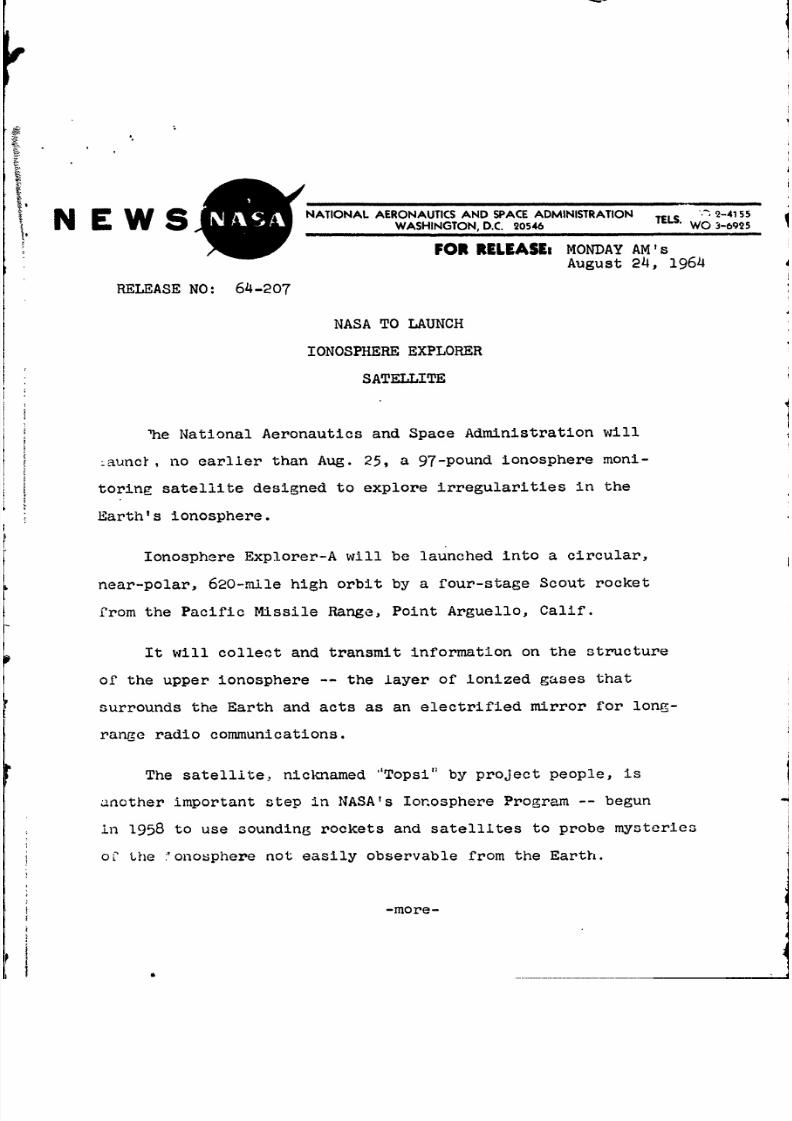
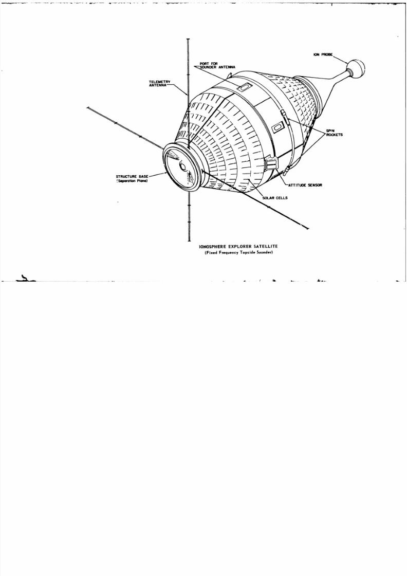
IONOSPHERE EXPLORER SATELLITE
(Fixed Frequency Topside Sounder)
8/7/2019 Ionosphere Explorer (Explorer XX) Press Kit
http://slidepdf.com/reader/full/ionosphere-explorer-explorer-xx-press-kit 6/22
-4-
TECHNICAL INFORMATION
Satellite Structure
The 97-pound satellite is conical, shaped something like
a chess pawn. The main section is 26 inches in diameter and
324- inches high. Mounted at the top is a ball-shaped ion mass-
spectrometer four inches in diameter. This mass-spectrometer is
at the end of a 10-inch tapered boom, giving the satellite an
overall length of 461 inches. Power is provided by nickel-
cadmium storage batteries which are supplied with electricity
from 2,400 solar cells mounted around the side of the satellite.
Protruding from the 26-inch diameter midsection are Three
sets of long sounding antennas or dipoles. One set measures
122 feet from tip to tip and two sets are 62 feet across. The
antennas will be extended after the satellite is in orbit. They
will transmit the soundings for the primary experiment on board.
Orbit
The satellite will be launched into a circular orbit angled
at 80-degrees with the Earth's equator. Separation from the
Scout's fourth stage will occur about 55 minutes after lift-off
and about 1,500 miles southeast of the Cape of Good Hope moving
northward over the Indian Ocean. The satellite will complete one
full orbit about every hour and 45 minutes.
-more-
8/7/2019 Ionosphere Explorer (Explorer XX) Press Kit
http://slidepdf.com/reader/full/ionosphere-explorer-explorer-xx-press-kit 7/22
-5-
The near-polar orbit was selected to obtain ionosphere
measurements at a number of stations, but concentrating on those
located along the 75-degrees west meridian from the Arctic to
the near Antarctic. A full cycle of daylight and seasonal
variations in the upper ionosphere can be measured by each of
the stations. Lifetime of the satellite is expected to be one
year although three m-onths of data will fulfill most of the
desired objectives.
The Ionosphere
Both as a device for long-distance radio communications
and as an object of scientific study, the ionosphere still is
inadequately understood. It is constantly sprouting several
new puzzles for each one that is laid to rest.
On December 12, 1901, as he manipulated a receiver in a
radio shack at St. John's, Newfoundland, an Italian, Marchese
Guglielmo Marconi, captured a radio signal that had been sent
from Poldhu in Cornwall, England, a good 2,000 miles away.
Clear~y, this experiment cast doubt upon the then generally
accepted theory that electromagnetic waves traveled through air
in a straight line, for a straight line connecting Poldhu with
St. John's would have to pass througha substantial quantity of
-more-
8/7/2019 Ionosphere Explorer (Explorer XX) Press Kit
http://slidepdf.com/reader/full/ionosphere-explorer-explorer-xx-press-kit 8/22
the Atlantic Ocean. Two groups of theoreticians formed to
offer possible explanations. One group, basing its position
on experience with light waves, suggested that the radio waves
had been bent o':er and along the curved surface of the Earth
by a process known as diffraction. However, the long interval
of curvature of the Earth and also the strength of the signal
received by Marconi worked against acceptance of this theory.
The foremost exponents of an altogether different explana-
tion were Dr. Oliver Heaviside, an Englishman, and an American,
Dr. Arthur E. Kennelly, who in 1902 suggested simultaneously
that the radio signals transmitted in England had struck a
reflecting layer in the atmosphere, which prevented them from
escaping to space and instead returned them to Earth. The
Kennelly-Heaviside layer theory generally was accepted, although
almost a quarter century would pass before radio sounding techniques
were sufficiently refined to permit measurements that accurately
demonstrated the existence of such a reflecting layer.
The extent to which a radio wave will penetrate into the
ionosphere before its energy has been redirected toward the ground
by reradiation from free electrons depends largely upon the
Frequency of the signal. Generally speaking, radio waves of
frequencies higher than about 15 megacycles (15 million cycles per
second) will pass through the ionosphere and escape to space.
-more-
8/7/2019 Ionosphere Explorer (Explorer XX) Press Kit
http://slidepdf.com/reader/full/ionosphere-explorer-explorer-xx-press-kit 9/22
-7-
For radio sounding -- in which the time of delay of a radio
signal echo is a measure of the height of the reflecting layer
-- frequencies of one to ten megacycles usually are used.
The efficiency of a particular ionized region for the re-
flection of radio waves depends .both on the number of free
electrons and the atmospheric density, because electrons can
collide with the heavy, neutral atoms or molecules. When such
a collision takes place, it stops the radio emission of the
,lectron because its energy is given up to the colliding particle.
The lowest layer of the ionosphere, therefore, tends to act as a
kind of radio-absorbing sponge because the high density of atoms
and molecules does not permit much free electron vibration.
During times of intense solar activity, when ionizing radiation
reaches deeper into the atmosphere, this absorbing layer broadens
and the result is the radio blackout associated with geomagnetic
storms.
Scientific ObJectives
The satellite is a self-sufficient space platform equipped
with six radar sets, a two-way communications system, a tracking
beacon and a solar power system. Its primary job will be to take
radio "soundings" of the upper ionosphere at six fixed frequencies.
This technique is similar to that used by a world-wide network of
around ionosphere sounding stations which obtain data on the lower
-more-
it4
8/7/2019 Ionosphere Explorer (Explorer XX) Press Kit
http://slidepdf.com/reader/full/ionosphere-explorer-explorer-xx-press-kit 10/22
| r -
- S -
A- --. - - - - - -
- - - By
I- I r Rs Con
> i - -
-fi - | - -
- - - - L - .
- - - w .- - - - -
-- s ; . - - -
- - - - - - - - - - - - - . 2
- - z
1wsEwEswwwaswsew==ssswsews
- -- :----
Am -}1 HM---- l - j - - . ]- ^- l - a - , A-- i- I - I -. {1I------- - - - -
=- *- -
- - -E EA--- - -
- --
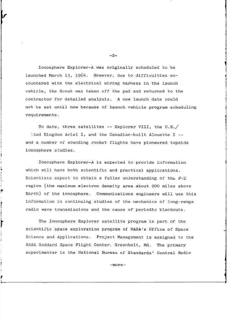
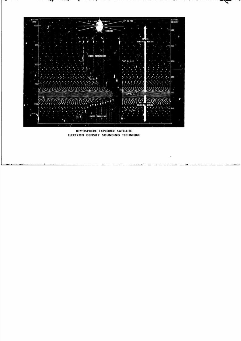
IONOSPHERE EXPLORER SATELLITE
ELECTRON DENSITY SOUNDING TECHNIQUE
8/7/2019 Ionosphere Explorer (Explorer XX) Press Kit
http://slidepdf.com/reader/full/ionosphere-explorer-explorer-xx-press-kit 11/22
-8-
regions or bottomside of the ionosphere. Low-frequency radar
signals are transmitted at specific intervals. These signals are
reflected or "bounced back" when they reach certain levels of
electron density in the ionosphere.
Feasibility of the sounding techniquie used by the satellite
was proved by two sounding rocket flights which carried simplified
Ionosphere Explorer instruments into the upper ionosphere. Thesees
experiments were conducted by the Central Radio Laboratory from
the NASA Wallops Island, Va., launch site June 24 and Oct. 13, 1961.
In orbit, the Ionosphere Explorer will make a sounding with
each of its six frequencies every one-tenth of a second. Signals
will reflect back as various electron density levels are reached.
Because a complete sounding can be performed in a brief period X
during less than one mile of forward motion by the satellite, an X
individual sounding is accomplished over an essentially fixed lo-
cation.
The ion mass-spectrometer will gather data on ion concentra-
tion and temperature in the immediate vicinity of the satellite's
orbit. This information will be correlated with the sounding in-
formation.
A secondary mission objective is to obtain readings of cosmic
noise, using the same frequencies employed for the sounding experi-
ment. Cosmic noise is radio noise coming from sources outside the
solar system.
-more-
8/7/2019 Ionosphere Explorer (Explorer XX) Press Kit
http://slidepdf.com/reader/full/ionosphere-explorer-explorer-xx-press-kit 12/22
-9-
Electron measurements over all geomagnetic latitudes and
the full daily cycle will provide information on: (1) ioniza-
4tion diffusion in the F-2 region; (2) horizontal movements or
irregularities in electron distribution in this region; (3)
fluctuations caused by tidal movement, and (4) the mechanismor
mechanisms which produce ionospheric storms,
Scientists hope that the information will help explain such
events as the "Sprea0-F Phenomenon" which consists of large patches
of irregularities in the F-2 region frequently observed at night
in the polar and equatorial regions. Other mysteries to be' ex-
ploredinclude "radio-wave ducting," a process in which radio
energy is guided along the Earth's magnetic field; the relation of
density formations with magnetic disturbances; and the degree of
iconnectedness" in the F-2 region between the northern and
southern hemispheres.
The sounding technique used by the Ionosphere Explorer is
complementary to that used by the Canadian-built Alouette ionosphere
satellite launched by NASA Sept. 29, 1962. However, emphasis and
instrumentation between the two are different.
Alouette was designed by the Canadian Defence Research
Telecommunications Establishmejt pr- marily to investigate in detail
the vertical distribution of electron densities. Its sounders employ
a swept frequency technique ranging from 0.5 to 12 megacycles.
-more-~
8/7/2019 Ionosphere Explorer (Explorer XX) Press Kit
http://slidepdf.com/reader/full/ionosphere-explorer-explorer-xx-press-kit 13/22
-10-
The sounding cycle takes lb seconds during which time Alouette
travels about 60 miles.
While the vertical readings are outstanding -- and tLouette
has sent more than 100,000 readings or Monograms since it was
orbited -- the horizontal profiles it obtains do not give a de-
tailed picture of the horizontal irregularities. The Ionosphere
Explorer, using its fixed frequency technique and rapid individual
readings, will do this job.
Scout Launch Vehicle
Scout is a multi-stage launch vehicle using four solid pro-
pellant: rocket motors capable " carrying payloads of varying
sizes on orbital, space probe or reentry missions. S,;out is 72
feet long and weighs 20 tons at lift-off.
Scout was developed by NASA's Langley Research Center,
Hampton, Va. It is manufactured by Ling-Temco-Vought, Inc., Dallas,
Tex.
The four motors are interlocked with transition sections
which contain guidance, control ignition, instrumentation systems.
separation mechanisms, and the spin motors required to orient the
fourth stage. Guidance is provided by an autopilot and control
achieve' by a combination of aerodynamic surfaces, jet vanes, and
hy:1ro7en peroxide jets.
-more-
8/7/2019 Ionosphere Explorer (Explorer XX) Press Kit
http://slidepdf.com/reader/full/ionosphere-explorer-explorer-xx-press-kit 14/22
Scout is capable of placing a 240-pound payload into a
300-mile orbit or of carrying a 100-pound scientific package
some 7,000 miles away from Earth.
Scout stages include the following motors:
First stage: Algol IIA (AeroJet Jupiter Senior)
- 105,000 pounds thrust burning 68
seconds.
Second stage: Castor (Thiokol Improved Sergeant)
- 55,000 pounds thrust burning 40
seconds.
Third stage: Antares (ABL S-259)
- 15,000 pounds thrust burning 33seconds.
Fourth stage: Altair II (ABL X-258)
- 5,798 pounds thrust burning 26
seconds.
Flight Sequence
The satellite, about 55 minutes after launch, will separate
from the fourth stage and should be in its desired 600-mile-plus
orbit. It will be moving northward over the Southern Indian Ocean,
having passed over the Antarctic.
Extension of the antennas then will be initiated. Before the
antennas are extended to 12 feet, two tiny de-spin rockets mounted
on the satellite will be fired to reduce the satellite spin rate to
-more-
8/7/2019 Ionosphere Explorer (Explorer XX) Press Kit
http://slidepdf.com/reader/full/ionosphere-explorer-explorer-xx-press-kit 15/22
a safe level of about 16 rpm. This is to prevent possible
damage to the sounding antennas due to coning motion of the
satellite.
Deployment of the antennas is scheduled to take about 20
minutes. The satellite will lose virtually all its spin, because
the long antennas will greatly increase the moment of inertia.
Once the antennas are extended, another pair of spin rockets will
be ignited to increase the satellite spin to the desired in-orbit
rate of 2.3 revolutions per minute.
Tracking and Data Acquisition
Data transmitted by the Ionosphere Explorer will be acquired
by ten stations already being operated by the United States, Canada
or the United Kingdom. Each is capable of acquiring data from the
satellite over an area equivalent to that of the continental United
States.
The stations are separated into three categories, by type
of data desired:
Ionosphere Explorer Meridional Stations (75 degrees West
Meridian)
Resolute Bay, Northwest Territories, Canada
St. Johns, Newfoundland
-more-
8/7/2019 Ionosphere Explorer (Explorer XX) Press Kit
http://slidepdf.com/reader/full/ionosphere-explorer-explorer-xx-press-kit 16/22
-13-
East Grand Forks, Minn.
Ft. Myers, Fla.
Quito, Ecuador
Santiago, Chile
South Atlantic (Special United Kingdom Station)
College, Alaska
Northern Latitude Stations (Primary interest to Canada)
Resolute Bay, Northwest Territories
St. Johns, Newfoundland
College, Alaska
Special Stations (Primary interest to the United Kingdom)
Winkfield, England
Singapore
South Atlantic
Information received at these stations will be recorded on
magnetic tape and converted to ionograms on photographic film.
Primary responsibility for processing and reduction of data
is charged to the National Bureau of Standards' Central Radio
P opagation Laboratory in Boulder, Colo. Selective processing of
2osmc noise and ionorram data will be accomplished by Goddard
opae Flif~ht Conter. Limited data processing will be done by
Ca.lacadian and United Kingdom agencies.
-more-
8/7/2019 Ionosphere Explorer (Explorer XX) Press Kit
http://slidepdf.com/reader/full/ionosphere-explorer-explorer-xx-press-kit 17/22
-14-
Ionosphere Explorer Team
NASA's Office of Space Science and Applications has overall
responsibility for the Ionosphere Explorer program and project
management is at the Goddard Space Flight Center.
Primary experimenter is the National Bureau of Standards'
Central Radio Propagation Laboratory, Boulder, Colo., of the U.S.
Department of Commerce. The ion mass-spectrometer was provided
by the University College of London, England.
Design and construction of the satellite was done by the
Airborne Instruments Laboratory of Cutler-Hammer, Inc., Deer
Park, N.Y., under contract to the Goddard Space Flight Center.
The Scout launch vehicle is managed by the NASA Langley
Research Center, Hampton, Va. Scout prime contractor is Ling-
Temco-Vought, Dallas, Texas.
Canada and Great Britain will cooperate in obtaining data from
the Ionosphere Explorer at special stations located in Northern
Canada, the Far East and the South Atlantic Ocean. These will
supplement the regular satellite tracking stations operated by the
Goddard Space Flight Center as part of the STADAN network.
Logistic and launch support services a; Point Arguello are
provided by the Goddard Launch Operations group and the Pacilic Launch
Orerations Office.
-more-
8/7/2019 Ionosphere Explorer (Explorer XX) Press Kit
http://slidepdf.com/reader/full/ionosphere-explorer-explorer-xx-press-kit 18/22
-15-
The Scout launching site at Point Arguello is operated
jointly by NASA and the Department of Defense. Scout launchings
are accomplished by the Air Force's 6595th Aerospace Test Wing
in cooperation with NASA
Key officials responsible for the Ionosphere Explorer
satellite and its experiments are:
NASA Headquarters
Dr. Homer E. Newell, Associate Administrator for Space Scienceand Applications
Dr. John E. Naugle, Director, Physics and Astronomy ProgramsDivision
M. J. Aucremanne, Ionosphere Explorer Program Manager
Goddard Space Flight Center
Dr. Harry J. Goett, Director
Dr. John W. Townsend, Jr., Associate Director, Office of SpaceScience and Satellite Applications
John E. Jackson, Project Manager and Project Scientist
E. Dale Nelsen, Assistant Project Manager
Robert H. Gray, Manager, Goddard Launch Operations
Joseph B. Schwartz, Associate Manager, Goddard Launch Operations(PMR)
J. M. Bridger, Scout Rocket Coordinator
Lazu--ey Research Center
Eugene D. Schult, Scout Project Manager
-more-
8/7/2019 Ionosphere Explorer (Explorer XX) Press Kit
http://slidepdf.com/reader/full/ionosphere-explorer-explorer-xx-press-kit 19/22
-16-
Central Radio Propagation Laboratory (National Bureau of Standards)
Robert W. Knecht, Project Manager
W. Calvert, Project Leader
University College, London, England
Dr. R. L. R. Boyd
Dr. A. P. Willmore
-more-
8/7/2019 Ionosphere Explorer (Explorer XX) Press Kit
http://slidepdf.com/reader/full/ionosphere-explorer-explorer-xx-press-kit 20/22
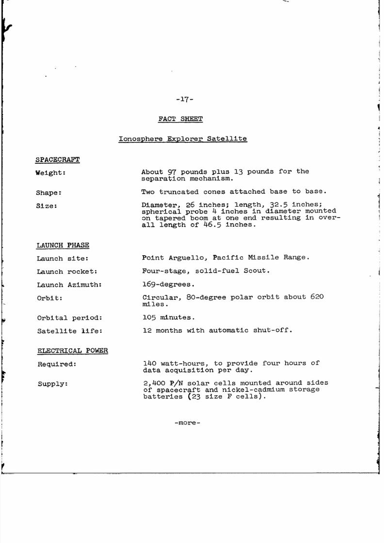
-17-
FACT SHEET
Ionosphere Explorer Satellite
SPACECRAFT
Weight: About 97 pounds plus 13 pounds for theseparation mechanism.
Shape: Two truncated cones attached base to base.
Size: Diameter, 26 inches; length, 32.5 inches;spherical probe 4 inches in diameter mounted
on tapered boom at one end resulting in over-
all length of 46.5 inches.
LAUNCH PHASE
Launch site: Point Arguello, Pacific Missile Range.
Launch rocket: Four-stage, solid-fuel Scout.
Launch Azimuth: 169-degrees.
Orbit: Circular, 80-degree polar orbit about 620
miles.
Orbital period: 105 minutes.
Satellite life: 12 months with automatic shut-off.
ELECTRICAL POWER
Required: 140 watt-hours, to provide four hours ofdata acquisition per day.
Supply: 2,400 P/N solar cells mounted around sides
of spacecraft and nickel-cadmium storage
batteries (23 size F cells).
-more-
8/7/2019 Ionosphere Explorer (Explorer XX) Press Kit
http://slidepdf.com/reader/full/ionosphere-explorer-explorer-xx-press-kit 21/22
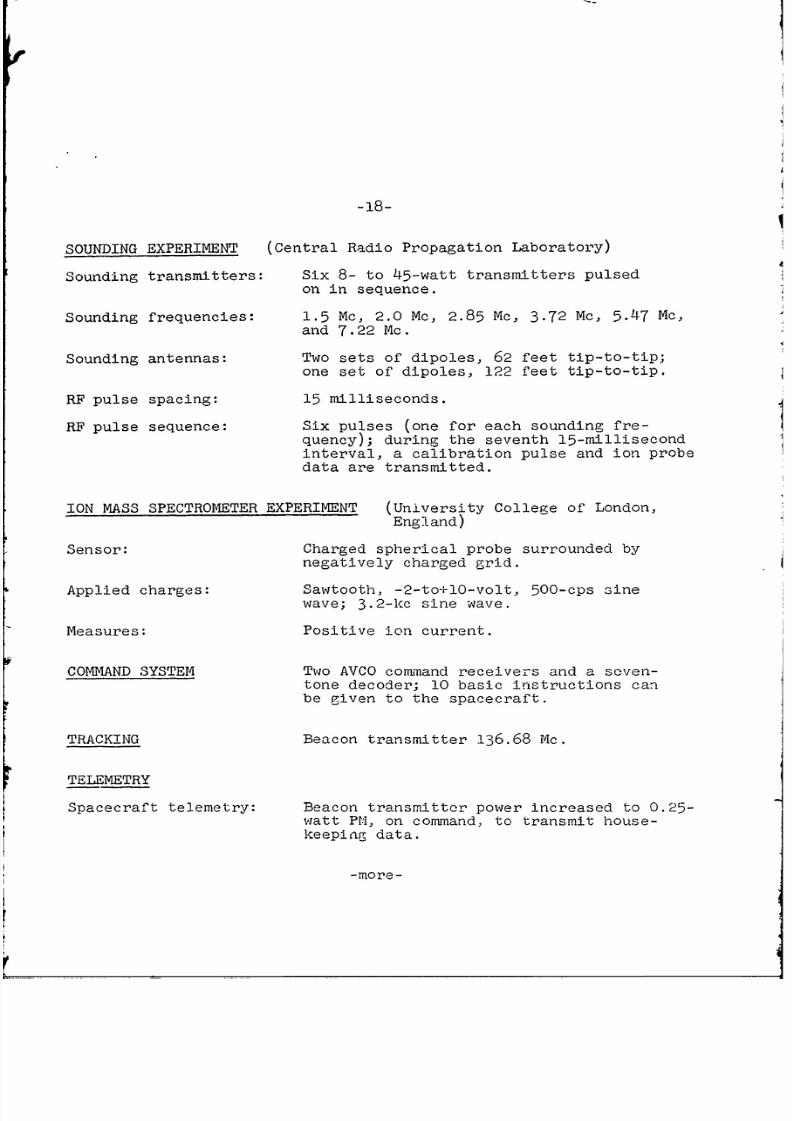
SOUNDING EXPERIMENT (Central Radio Propagation Laboratory)
Sounding transmitters: Six 8- to 45-watt transmitters pulsedon in sequence.
Sounding frequencies: 1.5 Mc, 2.0 Mc, 2.85 Mc, 3.72 Mc, 5.47 Mc,and 7.22 Mc.
Sounding antennas: Two sets of dipoles, 62 feet tip-to-tip;one set of dipoles, 122 feet tip-to-tip.
RF pulse spacing: 15 milliseconds.
RF pulse sequence: Six pulses (one for each sounding fre-quency); during the seventh 15-millisecondinterval, a calibration pulse and ion probe
data are transmitted.
ION MASS SPECTROMETER EXPERIMENT (University College of London,England)
Sensor: Charged spherical probe surrounded bynegatively charged grid.
Applied charges: Sawtooth, -2-to-l0-volt, 500-cps sine
wave; 3.2-kc sine wave.
Measures: Positive ion current.
COMMAND SYSTEM Two AVCO command receivers and a seven-
tone decoder; 10 basic instructions canbe given to the spacecraft.
TRACKING Beacon transmitter 136.68 Mc.
TELEMETRY
Spacecraft telemetry: Beacon transmitter power increased to 0.25-watt PM, on command, to transmit house-
keeping data.
-more-
8/7/2019 Ionosphere Explorer (Explorer XX) Press Kit
http://slidepdf.com/reader/full/ionosphere-explorer-explorer-xx-press-kit 22/22
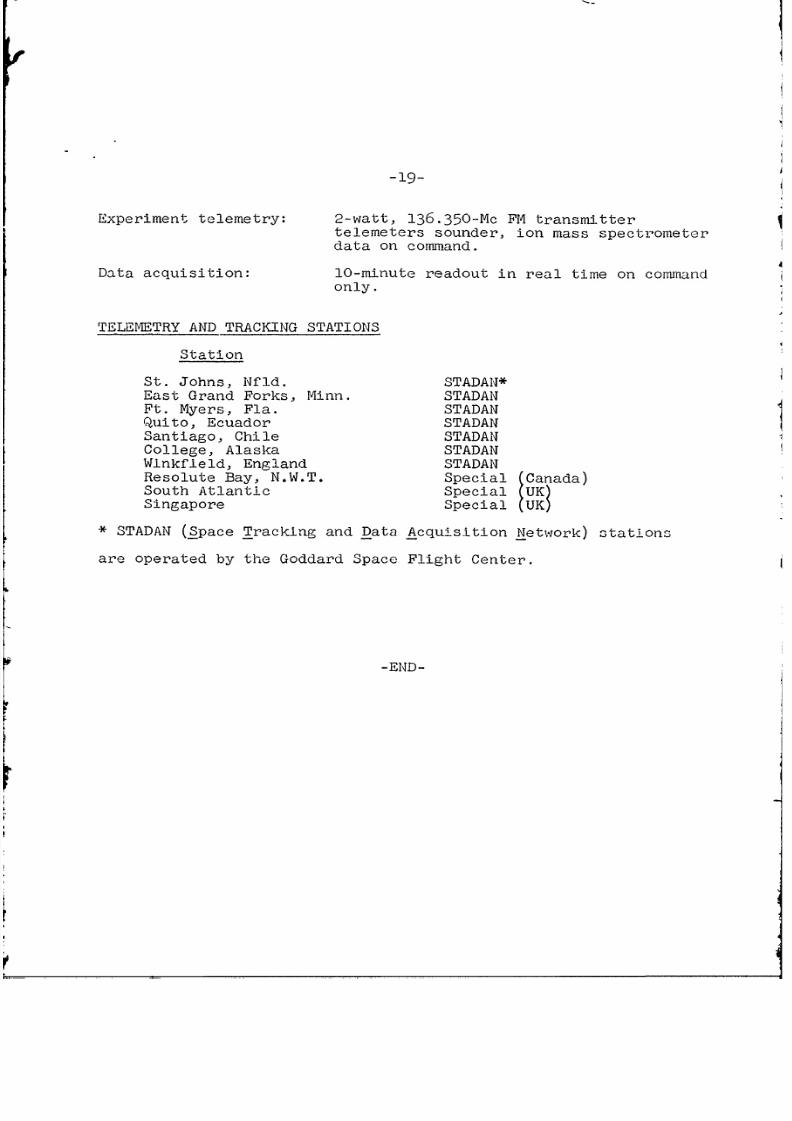
-19-
Experiment telemetry: 2-watt, 136.350-Mc FM transmittertelemeters sounder, ion mass spectrometerdata on command.
Data acquisition: 10-minute readout in real time on commandonly.
TELEMETRY AND TRACKING STATIONS
Station
St. Johns, Nfid. STADAN*East Grand Forks, Minn. STADANFt. Myers, Fla. STADANQuito, Ecuador STADANSantiago, Chile STADANCollege, Alaska STADANWinkfield, England STADANResolute Bay, N.W.T. Special (Canada)South Atlantic Special (UK)Singapore Special (UK)
* STADAN (Space Tracking and Data Acquisition Network) stations
are operated by the Goddard Space Flight Center.
-END-