IOM Progressing Cavity Pump (API 676)
114
NEMO ® -Pump Number of confirmation order Date of issue Tel. 0049 - (0) 86 38 - 63 0 Fax 0049 - (0) 86 38 - 67 999 e-mail: [email protected] Internet: www.netzsch-pumpen.de NETZSCH Mohnopumpen GmbH Geretsrieder Str. 1 D-84478 Waldkraiburg Type of machine NM…BY Number of machine Operating and Maintenance Instructions NEMO ® , NEMO PUMPEN ® , NEMOTUR ® , NEMO CERATEC ® , SBBPF ® , EBPBF ® , SM ® , NE ® , NM ® , TORNADO ® : Registered Trademarks of NETZSCH MOHNOPUMPEN GmbH (Translation of the original instructions) Important Note These Operating Instructions are designed to familiarize the User with the machine and its designated use. The Instruction Manual • is valid only for this machine (pls. see machine-no. / conf. no.) • contains important information on how to operate the machine safely, properly and efficiently. Observing these instructions helps to avoid danger, to reduce repair costs and downtimes and to increase the reli- ability and life of the machine • must be read and applied by any person in charge of carrying out work with and on the machine, such as: operation including setting up, troubleshoot- ing in the course of work, evacua- tion of production waste, care and disposal of fuels and consumables maintenance (servicing, inspection, repair) and/or transport • must always be available wherever the machine is in use • shall be completed by the Enduser and his authorized personnel with the national requirements in force for the prevention of accidents and the environmental protection In addition to the operating in- structions and to the mandatory rules and regulations for accident prevention and environmental pro- tection in the country and place of use of the machine, the generally recognized technical rules for safe and proper working must also be observed.
description
IOM Progressing Cavity Pump (API 676)
Transcript of IOM Progressing Cavity Pump (API 676)

NEMO®-Pump
Number of confirmation order
Date of issue
Tel. 0049 - (0) 8638 - 63 0Fax 0049 - (0) 8638 - 67 999e-mail: [email protected]: www.netzsch-pumpen.de
NETZSCH Mohnopumpen GmbH
Geretsrieder Str. 1
D-84478 Waldkraiburg
Type of machine
NM…BY
Number of machine
Operating andMaintenance Instructions
NEMO®, NEMO PUMPEN®, NEMOTUR®, NEMO CERATEC®, SBBPF®, EBPBF®, SM®, NE®, NM®, TORNADO®:Registered Trademarks of NETZSCH MOHNOPUMPEN GmbH
(Translation of the original instructions)
Important Note
These Operating Instructionsare designed to familiarize theUser with the machine and itsdesignated use.
The Instruction Manual
• is valid only for this machine (pls.see machine-no. / conf. no.)
• contains important information onhow to operate the machine safely,properly and efficiently. Observingthese instructions helps to avoiddanger, to reduce repair costs anddowntimes and to increase the reli-ability and life of the machine
• must be read and applied by anyperson in charge of carrying outwork with and on the machine,such as:
operationincluding setting up, troubleshoot-ing in the course of work, evacua-tion of production waste, care anddisposal of fuels and consumables
maintenance(servicing, inspection, repair)and/or
transport
• must always be available whereverthe machine is in use
• shall be completed by the Enduserand his authorized personnel withthe national requirements in forcefor the prevention of accidents andthe environmental protection
In addition to the operating in-structions and to the mandatoryrules and regulations for accidentprevention and environmental pro-tection in the country and place ofuse of the machine, the generallyrecognized technical rules for safeand proper working must also beobserved.


TABLE OF CONTENTS PAGE0.0
Date Name Signed Revision: 2
issued 26.09.95 Mangel Substitute for issue
approved 27.09.95 Eitler of 18.03.94
released 28.09.95 Hantschktext no. 30100
copy to: 95
Page
1 Safety Precautions 1.0
2 Description 2.0
3 Packing, Transportation, Storage 3.0
4 Installation Instructions 4.0
5 Start-up 5.0
6 Temporary Shutdown 6.0
7 Maintenance 7.0
8 Trouble-Shooting and Remedying 8.0
9 Dismantling and Assembly of the Pump Housing 9.0
10 Dismantling and Assembly of the Rotating Parts 10.0
11 Removal and Fitting of the Connecting Shaft 11.0
12 Dismantling and Assembly of the Shaft Sealing 12.0
13 Dismantling and Assembly of Special Units 13.0
14 Recommended Stock of Wear Parts 14.0
15 List of Spares and Sectional Drawing 15.0
16 List of After-Sales Service Centres 16.0
GB
Remark: Because of data transfer the text sheet printouts of our operatinginstructions do not contain a personal signature.


Continued Page 1.0R
1 SAFETY PRECAUTIONS
Date Name Signed Revision: 6
issued 16.06.03 Mangel Substitute for issue
approved 17.06.03 Denk of 31.10.96
released 17.06.03 Denktext no. 30100
copy to: 95
PAGE1.0
1 Safety Instructions
This manual contains basic instructions whichmust be observed when installing, operatingand servicing the machine / equipment. It isessential therefore for the user / installer orresponsible technician to read the manualthoroughly prior to installation and opera-tion.A copy of the manual must always be at handwhere the machine / equipment is being used.In addition to the general safety instructionslisted in this main section on safety, it is
necessary to observe the special safety rulesincluded in other sections of the manual, eg.for private use.
1.1 Safety Signs
The signs below are printed in the manual asgeneral hazard / danger symbols to markthose safety instructions whose non-obser-vance can result in danger to personnel or tothe machine / equipment. These signs are:
Hazard sign DIN 4844 - W9Danger to general public
Hazard sign DIN 4844 - W8Risk of electric shock
Risk of injury from machinery
Danger from suspended loads
Damage to machinery
Risk of injury to your eyes: goggles required.
GB

Continued Page 1.1
1 SAFETY PRECAUTIONSPAGE1.0R
Revision: 6 Date Name Signed
Substitute for issue issued 16.06.03 Mangel
of 07.10.96 approved 17.06.03 Denk
text no. 30100released 17.06.03 Denk
copy to: 95
Warning plates located directly on the pump/equipment showing for example the correctdirection of rotation or the fluid connectionsused must always be observed and kept com-pletely legible.
1.2 Personnel Qualifications andTraining
Operating, maintenance, inspection andinstallation staff must possess the correct qua-lifications for their work. Areas of responsi-bility, scope of authority and staff supervi-sion must be exactly defined by the user. Ifpersonnel do not have the necessary know-ledge they must receive due training andinstruction. If necessary, the user of the ma-chine / equipment can arrange for such trai-ning and instruction to be provided by themanufacturer / supplier. The user must alsomake sure that the content of the manual isfully understood by the staff concerned.
Responsibilites
All work on and operation of the pump/equipment should be carried out by trained/competent and qualified operators, trades-men and / or engineers as appropriate.
Any person responsible for or in charge of
– working with lifting gear and ropes whenmoving a pump / equipment will have to beduly instructed prior to doing the transpor-tation job;
– mounting a drive to a pump / equipmentmust be qualified / trained as an industrialmechanic / technician;
– setting up installations into a plant must bequalified / trained as an industrial mechanic/technician and must be familiar with thedesign and functioning of the plant in whichthe pump / equipment is being installed;
– doing work on starting up, operation andmaintenance must gain knowledge of thepump / equipment principle prior to perfor-ming such works and must study the safetyinstructions and the manual thoroughly;
– doing repair works, and prior to doing suchworks, must be trained and skilled in the job.He must have due knowledge of the pump/equipments specific details set up in the repairinstructions. Unskilled personnel must betrained and repair works checked.
1.3 Dangers arising from Non-Observance of the SafetyInstructions
Non-observance of the safety instructions canresult in danger to personnel as well as to theenvironment and the machine. Non-obser-vance of the safety instructions can result inthe loss of claims for compensation.
Non-observance of the safety instructions canhave, for example, the following consequen-ces:
� Failure of essential functions of themachine / equipment
� Failure of mandatory maintenanceand servicing methods
GB

Continued Page 1.1R
1 SAFETY PRECAUTIONS PAGE1.1
Date Name Signed Revision: 6
issued 16.06.03 Mangel Substitute for issue
approved 17.06.03 Denk of 07.10.96
released 17.06.03 Denktext no. 30100
copy to: 95
� Danger to personnel from electricity,machinery and chemicals
� Danger to the environment fromleakage of hazardous substances.
1.4 Safety Conscious Working
In addition to the safety instructions listed inthe manual, it is essential to observe thenational accident prevention directivescurrently in force and any of the users owninternal regulations concerning work andsafety.
1.5 Safety Instructionsfor the User / Operator
� If there is a risk of danger from any hotor cold machine component, the usermust fit protective guards to preventsuch components from being touched(according to Standard EN 563).
� Protective guards fitted to preventcontact with moving parts (eg.couplings) must be in position whenthe machine / equipment is in use.
� Leakages (eg. from a shaft seal) ofhazardous materials (eg. explosive,toxic, hot material) must bedischarged in such a way thatneither personnel nor theenvironment are placed at risk.Legal directives must be observed.
� All possible danger from electricity mustbe eliminated (for details see eg. theregulations of your local power supplycompany).
A NEMO® pump is reliable and of high qua-
lity. Especially if in a NEMO® pump, partsmade of technical ceramics, such as theNEMO CERATEC® ceramic rotor, have beenbuilt in, this guarantees for a long econo-mic life-time.The ceramic rotor and other ceramic partsin a pump can cause a danger if they arenot used properly and as intended. Theoperator has to investigate, whatconsequences are linked to a malfunctionof the ceramic materials and if safety mea-sures have to be taken to protect peopleand environment.
Beyond the warranty of our standard busin-ess conditions and the assured characteri-stics named in the confirmation of order,any liability for –consequential – harm cau-sed by defect is excluded. We are only liablefor intent or gross negligence.
GB
Continued Page 1.2
1 SAFETY PRECAUTIONSPAGE1.1R
Revision: 8 Date Name Signed
Substitute for issue issued 16.06.03 Mangel
of 07.10.96 approved 17.06.03 Denk
text no. 30100released 17.06.03 Denk
copy to: 95GB
1.6 Safety Instructions forMaintenance, Inspectionand Installation
The user must ensure that all maintenance,inspection and installation work is carried outby authorized and qualified personnel whounderstand the operating instructions andare adequately trained.
Work on a pump / equipment must only becarried out with the machine stopped andelectrical power supply turned off. The pump/equipment must not be under any pressureand must have cooled off. All proceduresdetailed in these operating instructions onthe stoppage of the machine must always beadhered to.
Pumps / equipment which convey harmfulmedia must be decontaminated.Immediately after the maintenance work isfinished all safety devices and guards must bere-installed and the safety trips must betested.Before putting the machine back into opera-tion the points detailed in section "Start-up"should be observed.
1.7 Unauthorized Modifications andManufacture of Spares
Modifications or changes to machines / equip-ment are only permissible with the manu-facturer's agreement. Original spare partsand accessories authorized by the manufac-turer ensure safety.The use of other components revokes any lia-bility for consequences which may result.For operational and machinery safetyreasons the delivered machines may only beoperated with original spare parts and sup-porting materials according to our manufac-turer’s guidelines.
1.8 Use Specified, ImproperApplication, Operational andMachinery Safety
Delivered machinery / equipment is onlyguaranteed safe for the use specified.
This machine / equipment was designed inaccordance with the prescribed conditions ofuse.The limits of use are laid down in the con-ditions of use and should in no way be ex-ceeded.
In accordance with current EU-law regardingthe operator’s liability for plants and the cor-responding question regarding the authori-ty to operate such plants, we have to pointout the conditions under which our pro-ducts can be operated:
Spare and wearing parts from other manu-facturers are not authorised for use in ourproducts and are contrary to the instructionscontained in the operational manual youreceived from us. In this case adverseeffects on the operational and workingsafety together with the reliability can not beexcluded. Responsibility for all effects on theoperation permit for your plant as a wholeas well as for the consequences to your lia-bility is totally your responsibility.
For the operational safety of its productsNETZSCH Mohnopumpen GmbH operatesextensive quality and safety procedurestogether with continuous production con-trol, which applies to the development andproduction of both pumps and spare parts.Hereby can the component compatibility andsuitability be determined and ensured.

Continued Page 1.2R
1 SAFETY PRECAUTIONS
Date Name Signed Revision: 5
issued 30.03.10 Marchionini Substitute for issue
approved 30.03.10 Denk of 17.06.03
released 30.03.10 Denktext no. 30100
copy to: 95
PAGE1.2
GB
1.9 Specific Points for the Use of a
NEMO® Pump
A NEMO ® pump must be used for thepurpose only for which it was sold.
If you change or wish to change the processmedium, you must check with either thesupplier or manufacturer that the pump issuitable for the new medium. This is espe-cially important with aggressive, poisonous orotherwise hazardous substances.
Pump criteria include:
1. Compatibility with the medium
2. Suitability for seal design / material, especially the shaft seal
3. Resistance to pressure and temperature of the medium.
Please remember that the NEMO® pump is apositive displacement pump and as such isable to generate an impermissibly high pres-sure.
A blockage or the chance closure of a valvein the discharge line can cause a pressure risemanifold as high as can be tolerated by theinstallation. This can result in the bursting ofpipes, which must be avoided especially inthe case of dangerous media.
Corresponding safety equipment musttherefore be installed, for example anemergency stop button, a pressure reliefvalve with return pipe or a bursting disc.
During maintenance and repair work on thepump please note the following:
1. Ensure that the pump drive can notbe turned on without authorization.
2. When opening the pump follow the instructions for handling the medium (eg. protective clothing, no smoking etc).
3. Before putting the pump back into operation ensure that all guards and other safety devices (eg. drive–belt protection, coupling protection) areproperly re–installed.
Always bear in mind your safety duringoperation, maintenance and installa-tion of equipment. Please adhere tothe EC-Directive for Machinery inclu-ding the national regulations and fol-low the European Standard EN 292 withthe accident prevention rules laid downby the trade unions and other appro-priate technical institutions.
Continued Page 1.3
1 SAFETY PRECAUTIONSPAGE1.2R
Revision: 2 Date Name Signed
Substitute for issue issued 16.06.03 Mangel
of 27.03.97 approved 17.06.03 Denk
text no. 30100 released 17.06.03 Denk
copy to: 95GB
1.10 Notes on Inspection and Repair
The legal regulations for safety at work,such as regulations for the workplace, regu-lations governing dangerous materials, acci-dent prevention, environmental protectioneg. regulations on disposal and water balan-ce obligate all commercial business to pro-tect their employees and / or people and theenvironment from adverse effects cau-sed by contact with dangerous mate-rials.
Important:
Inspection / repair of machinery and its partsonly takes place when a safety conformitycertificate has been completed by an
authorized and qualified specialist. Please usea copy and leave the original in the operati-on and maintenance manual.
Where special safety precautions are neces-sary in spite of careful emptying and clea-ning of the machinery, the necessary infor-mation must be given.
Machinery operating with radio-active mediawill only be repaired or inspected by one ofour specialist engineers under the safety ofthe owner.
The safety conformity certificate is part ofthe inspection / repair service. We reservethe right to refuse acceptance of this order /service for other reasons.

Continued Page 1.3R
1 SAFETY PRECAUTIONS PAGE1.3
Date Name Signed Revision: 3
issued 01.02.10 Marchionini Substitute for issue
approved 01.02.10 Denk of 24.10.03
released 01.02.10 Denktext no. 30100
copy to: 95
1.11 Instructions concerning explosion protection
The instructions below are to be considered and kept to when using pumps in potentially explosive areas in order to guarantee durable explosion protection of the pumps and avoid any danger of ignition.
In accordance with the regulations 94 / 9 / EC, the pumps are admitted for use in the area II 2G IIB T 4 or II 2G IIB T 3 or II 2GD IIB T 4 (130 °C) or II 2GD IIB T 3 (195 °C).
It is to be taken into account that in case of aggregates the components (e.g. gears, couplings) mounted on the pumps must comply with the regulations 94 /9 / EC as well. The relevant documentation concerning these components is to be considered. The application area of aggregates is determined by the application area of the mounted component with the lowest approval and thus may deviate from the allowed application area of the pump.
The maximum conveying product temperatures apply when mechanical seals of Messrs. Burgmann with carbide – carbide and carbide – carbonas sliding material combinations are used.In the case of other manufacturers or other sliding material combinations it is necessary to consult the manufacturer.
1. Assembly and repair in potentially explosive areas
When performing assembly and repair work, it is to be seen to it that no dangers of ignition arise especially during heating up the pump parts. This means e.g. heating up by explosion-proof heating devices or exclusively in non-explosive areas. The temperature of the heated part and the ignition temperature of the materials by which the danger of explosion may be caused are to be considered.
2. Dry-running protection
Under no circumstances is the pump to run dry.The pump is to be equipped with an appropriate dry-running protection device. The device for dry-running protection should be self-regulating.
GB
Temperature categorymax. surface temperature
for dustmax. temperature of the
conveying product
T 4 130 °C 100 °C
T 3 195 °C 165 °C
T 2 295 °C 265 °C
T 1 445 °C 415 °C

Continued Page 1.4
1 SAFETY PRECAUTIONSPAGE1.3R
Revision: 1 Date Name Signed
Substitute for issue issued 13.08.03 Mangel
of 17.06.03 approved 13.08.03 Denk
text no. 30100released 13.08.03 Denk
copy to: 95GB
This means that this device can give alarm signals and/or switch off the pump also in case of failures in its own control system.
Dry-running protection concerning stationary immersion pumps (with mounting plate)
Operation is only permitted with redundant or self-regulating automatic devices to guarantee dry-running protection as well as to control the pump capacity.
Dry-running protection concerning movable immersion pumps (drum pumps)
The filling with liquid during the operation is to be ensured by specific requirements of behavior:
– Drum pumps may only be introduced in and removed from the container in switched-off condition
– Drum pumps, after being introduced in the container to be discharged, may only be started after they have immerged in the fluid.
– Drum pumps are to be switched off before they run dry or are to be switched off at once when specific noises ("slurping” or speed rise) suggest that dry running may or will immediately occur.
3. Overpressure protection
The pump must not be loaded over the maximum allowable pressure.The pump is to be equipped with an appropriate overpressure protection device. The pump must not convey against a closed slide valve.The overpressure protection device should be self-regulating.
4. Drives
The drives must be adjusted to the performance of each pump. In the case of a blocking of the pump, the drives must be turned off automatically by means of a motor protection unit.
5. Alignment of the drive (concerning the pump types SY / SH / SA / SO / SF / SP)
It is absolutely necessary that the drive be aligned within the maximum allowable tolerances. Incorrect alignment causes damage to the seals and the shaft bearings.
6. Potential equalization concerning immersion pumps
The immersion pumps are to be integrated in the potential equalization of the installation. Hand-operated movable immersion pumps are to be grounded before being introduced in the container. The connection to ground is to be maintained until the pump has been completely pulled out of the container. There must not be any potential difference between the pump and

Continued Page 1.4R
1 SAFETY PRECAUTIONS PAGE1.4
Date Name Signed Revision: 1
issued 12.08.03 Mangel Substitute for issue
approved 13.08.03 Denk of 17.06.03
released 13.08.03 Denktext no. 30100
copy to: 95
a conductive container. This means that container and pump are to be connected at a common grounding point and thus be conductively connected with each other.(see information brochure "Statische Elektrizität, Zündgefahren und Schutzmaßnahmen" (Static electricity, dangers of ignition and preventive measures); Publisher: "Internationale Sektion für die Verhütung von Arbeitsunfällen und Berufskrankheiten in der chemischen Industrie der IVSS" (International section for the prevention of employment accidents and occupational diseases in the chemical industry of the ISSA (International Social Security Association)) , Heidelberg 1995).The hand-operated movable immersion pumps are to be provided with anindication referring to the grounding measure (pay attention to grounding).
7. Potential equalization concerning all other pump types (no immersion pumps)
All conductive parts of the pump are to be integrated in the potential equalization of the pumping set unless the conductive connection to the ground potential is guaranteed by the drive or connecting shafts or otherwise.
8. Stator
The stator is to be regularly checked for wear. When the allowable wear limit is reached, the stator is to be replaced. Before exchanging the conveying product, the pump operator has to consult the manufacturer concerning the durability of the stator unless the stator has already been confirmed for the intended application.
Inspection and maintenance interval of the stator:– in the case of an operating time of > 16 h/day, at least twice a year– in the case of an operating time of < 16 h/day, at least once a year.
9. Joints / joint lubrication
The sealing and the lubrication of the joints are to be regularly checked. If necessary, the seals and the lubricants are to be replaced.
Inspection and maintenance interval of the joints:– in the case of an operating time of > 16 h/day, at least twice a year– in the case of an operating time of < 16 h/day, at least once a year.
10. Inspection after initial startup
The aspects relevant for ensuring the explosion protection (such as lubrication and wear check) are to be checked six months after the initial startup of the pump at the latest.
11. Shaft bearings (concerning the pump types SY / SH / SA / SO / SF / SP)
Replacement of the bearings after 14,500 operating hours (according to prEN 13463-5: replacement after 90 % of the designated service life).
GB

Continued Page 1.5
1 SAFETY PRECAUTIONSPAGE1.4R
Revision: 2 Date Name Signed
Substitute for issue issued 30.03.10 Marchionini
of 24.10.03 approved 30.03.10 Denk
text no. 30100released 30.03.10 Denk
copy to: 95GB
12. Materials
Although being allowed as material for the pumps, aluminum should be avoided in potentially explosive areas. The pumps may only be used if, under the particular operating conditions, the materials are resistant to mechanical and/or chemical influences or corrosion such that the explosion protection will be maintained.
13. Noise development(concerning the pump types SO / BO / SF / BF / SP / BP)
As soon as unusual noises (such as knocking or rubbing) are realized, the pump is to be switched off. The cause of the failure is to be eliminated before the pump is reoperated. Regular check of the paddle equipment.
14. Direction of flow of immersion pumps
The direction of flow of immersion pumps always has to be from the endconnection piece to the pressure nozzle at the top. The reverse direction of flow is not allowed.
15. Mechanical seal of immersion pumps
Before the initial startup and after a prolonged shutdown, the mechanical seal is to be lubricated from outside before the pump is started. In this connection, the compatibility of the lubricant with the sealing material is to be considered.
16. Impurities in immersion pumps
Especially in the case of hand-operated movable immersion pumps it is to be seen to it that no impurities can get into the pump. The pumps are to be deposited only on clean and solid ground or else to be suspended.In case of unusual noises or power losses, the immersion pumps are to be switched off immediately.
17. Gland
If a gland packing is applied it has to be observed that the permitted temperature corresponding to the temperature category is not exceeded. Recommendation: fasten the screws of the stuffing box gland only with low torque (approx. 5 Nm).
18. Dust layer
No dust layer of more than 5 mm is allowed on the pumps. Rotating parts (likedrive shaft, bearing carrier and drive stool of paddle agitators) must not runin a dust layer. In respect of this the pumps have to be controlled at regular intervals and if necessary the dust has to be removed.

1 SAFETY PRECAUTIONS PAGE1.5
Date Name Signed Revision: 4
issued 16.06.03 Mangel Substitute for issue
approved 17.06.03 Denk of 07.10.96
released 17.06.03 Denktext no. 30100
copy to: 95
Safety Conformity Certificate
The machinery and its accessories together with this safety conformity certificate relatingto repair / inspection services given to the undersigned by ourselves
Machine Type .......................................Number .......................................Delivery Date ....................................... Delivery Note No. .......................................
was carefully emptied and cleaned both inside and �� yesout in preparation for shipment �� no
Special safety precautions with regard to health or �� necessarymedia endangered by water are to be implemented �� unnecessary
The machinery is set up to transport materials dangerousto health or water and came in contact with �� yesmedia containing harmful substances �� no
The following safety precautions are necessary with regard to irrigation media, overflow liquid and waste management:
.................................................................................................................................................
.................................................................................................................................................
We confirm that the above mentioned details are correct and complete and thatdespatch will follow in accordance with the legal requirements:
Company Telephone .............................................
........................................................................... Fax .............................................
........................................................................... Telex .............................................
Address
...........................................................................
...........................................................................
Name ............................................................. Position .............................................
....................................... ............................................. Date Company Stamp / Signature
GB


Continued Page 2.0R
2 DESCRIPTION AND GENERAL DATA PAGE2.0
Date Name Signed Revision: 2
issued 03.08.98 Mangel Substitute for issue
approved 04.08.98 Hantschk of 18.03.94
released 05.08.98 Hantschktext no. 30100
copy to: 95
2 Description
The NEMO® pump is a progressing cavitypump.The main components which determine thesystem discovered by Professor René Moineauare a rotating part, called the rotor and a sta-tic part, called the stator.The rotor is a helical screw with an extreme-ly large pitch, large thread depth and smallcentre diameter with round cross-section for1/2-geometry and elliptical cross-section for2/3-geometry. The stator has a two start orresp. 3 start thread and is double or resp. 1.5the pitch length of the rotor. This providesspace for the medium between the rotor andstator. When the rotor turns round inside thestator the medium moves continuously fromthe inlet to the outlet.
The universal NEMO® pump system unifiesmany positive characteristics of other pumptypes:
� Like centrifugal pumps NEMO® pumpshave no suction or pressure valves, but dohave a stable flow rate in proportion to thenumber of revolutions.
� Like piston pumps NEMO® pumps have asuction capability of up to 8.5 m vacuummetric.
� Like membrane and peristaltic pumps theNEMO® pump can transport every type ofinhomogenous, gaseous and abrasive media,as well as those that are not of a liquid con-sistency or contain solids and/or fibrous mate-rial.
� Like gear pumps and screw pumps theNEMO® pump is capable of coping with highmedium viscosities.
� Like piston, membrane, gear or screwpumps the NEMO® pump can perform dosingoperations.
Length and cross-sections through the rotorand stator with 1/2-geometry during arotation.
0°/360°
90°
180°
270°
STATOR
ROTOR
GB
Rotorposition

2 DESCRIPTION AND GENERAL DATAPAGE2.0R
Revision: 4 Date Name Signed
Substitute for issue issued 04.11.98 Mangel
of 05.08.98 approved 05.11.98 Denk
text no. 30100released 06.11.98 Hantschk
copy to: 95
2.2 General Data
Noise emissions:
The maximum permitted noise emission level at a work place is 70 dB (A).
The noise level was measured in accordance with DIN Standard 45635-24-01-KL2 to assure that the pump does not exceed 70 dB (A).
Noises generated by the drive and pipes are not included in the aboveemission value.
A prerequisite for the noise emission level of ≤ 70 dB (A) is that the pump is operated in a cavity free regime and is bolted to a concrete base.
GB
Length and cross-sections through the stator with rotor with reduced stator wall thickness
1/2-geometry
2/3-geometry

Date Name Signed Revision: 4
issued 23.06.98 Mangel Substitute for issue
approved 24.06.98 Denk of 07.12.94
released 25.06.98 Denktext no. 30100
copy to: 95
Continued Page 3.0R
3 PACKAGING, TRANSPORTATION, STORAGE PAGE3.0
3 Packaging, Transportation, Storage
3.1 Packaging and Transportation
NEMO® pumps are shipped in railroad containers or crates unless the customer specifies otherwise. The packings are labelled and symbols give the handling instructionsin accordance with DIN 55402.On receipt check for any transport damages. Transport damages should be reported to the transporter immediately.The pumps should be transported as closely as possible to the location of installation and only there should they be uncrated.
Uncrated horizontal pumps should be lifted by using a shackle which can be attached to the baseplate. The bolt holes of the frame or the lifting lugs attached to the baseplate could be used as shown on the installation drawing.
Vertical pumps should be lifted by using the bolt down holes,lifting lugs or shackles attached to the baseplate. This is shown onthe installation drawing. For most applications, the drive is mountedon top of the pump.
Be careful when lifting top heavy pumps. The centre of gravity may beabove the points where the lifting gear is attached to. If the case, secure additionally against tipping over!
Vertical pumps should not be deposited unless they are secured vertically.Hazards of tipping! Deposit only in horizontal position!
It is essential to avoid that the total pump unit be suspended witheye bolts of the motor or gear box. These eye bolts should be used for lifting the motor and/or the gear box only.
The Accident Prevention Rules, Section 18.4 relating to lifting accessories for the lifting of loads (VBG 9a) must be strictly adhered to.
Because of the variety of possible pump designs and applications, only general instructions can be given here. These should be good enough for experienced assemblymen or transportation experts.When in doubt, please ask for detailed information on the pump unit concerned.
GB

3 PACKAGING, TRANSPORTATION, STORAGE
Continued Page 3.1
PAGE3.0R
Revision: 4 Date Name Signed
Substitute for issue issued 23.06.98 Mangel
of 07.12.94 approved 24.06.98 Denk
text no. 30100released 25.06.98 Denk
copy to: 95
When moving the pump or unit on wheels strictly attend to the following:
� Pad lock the motor drive and secure against unintended starting up.
� Move the pump unit carefully and slowly, especially where the ground is uneven. Hazards of tipping!
� Ensure a stable position of the pump or unit at the operating /storage place and secure it by actuating all clamping devices on all the wheels or rollersagainst voluntary moving away.
� Where fitted loosely, carefully watch the pipe bends when pumping.Power of repulsion!
� Where necessary, secure the pump unit additionally with support blocks.
3.2 Storage
The pumps are preserved for transport unless specified otherwise.In cases of longer storage the pumps should be handled as follows until installation:
� Stator:
If the pump is not to be used immediately, then the elastomer along the contact line between rotor and stator may become permanently distorted (compression-set). This will increase the break away torque. Therefore, the stator should be removed and kept separately in a clean, cool and dry environment. Standard DIN 7716 summarizes detailed information on the storage of rubber products, some of which is gathered here, and the following notice applies to a storage for a period of up to six months.
General
Most of the rubber products may change their physical properties under unfavourable conditions or if treated improperly, which will result in a shorter lifetime. Or they may become useless through excessive hardening, aging, regenerating or permanent deformation, also because of blistering, cracking or other damages appearing on the surfaces. The changes may occur under the influence of oxygen, ozone, heat, light, humidity, solvents or because of storing the products under tension. If stored and treated properly, the rubber products will keep their properties, even over a long period of time (some years), almost unchanged. This does, however, not apply to uncured rubber compounds.
GB

Date Name Signed Revision:
issued 23.06.98 Mangel Substitute for issue
approved 24.06.98 Denk of
released 25.06.98 Denktext no. 30100
copy to: 95
3 PACKAGING, TRANSPORTATION, STORAGE PAGE3.1
Store room
The environment in which rubber products are being kept must be cool, dry, free of dust and rather airy, and they must not be stored in the open, not even in a weather sheltered space. Rubber products should be kept in surroundings not having less than minus 10 °C and not more than plus 15 °C. Store rooms should not be damp, and it must be ensured that there will be no condensation. Most favourable is an environment offering a relative humidity under 65 %. Rubber products must be protected against light, particularly direct sunlight or artificial light when having a high UV portion. They should furthermore be kept away from ventilation, especially draught, by wrapping them up. As ozone is very aggressive and harmful there should be no store room used which houses equipment likely to produce ozone, e.g. electric motors or other equipment which might bring about sparks or other electrical discharges. There must be no solvents, oil, grease, lubricants or any chemicals kept in a store room.
� Rotor
Please support with wooden blocks and cover up against harm from mechanical impact. For rotors of RCC (material number 1.2436):coat the surfaces with protective grease to avoid rusting.
� Shaft Sealing by packing gland
Remove the gland and coat the exposed shaft surface with grease.
� Pump parts in stainless steel
No grease coating necessary.
� Other, non-coated pump parts
Protect with grease.
� Drives
Please observe the drive supplier's instructions.
GB


Date Name Signed Revision:
issued 20.06.03 Mangel Substitute for issue
approved 20.06.03 Denk of
released 20.06.03 Denktext no. 30100
copy to: 95
Continued Page 4.0R
4 INSTALLATION INSTRUCTIONS PAGE4.0
4 Mounting and Installation
If the NEMO® pump was stored and the rotor grease protected:Remove the grease before installing the stator.Clean the rotor thoroughly in order to avoid unsuitability of the grease with the stator material and the pumping medium.
Screw the pump at all fixing points (bearing housing / drive stool, end stud, support feet) using all fixing bores securely down to the sub-structure (ground plate, machine frame, foundation etc.).
4.1 Direction of Rotation
The direction of rotation of the pump is given on the model plate and in the order confirmation. The direction of delivery of the
NEMO® pump is a function of the direction of rotation.
Changes must be agreed upon and confirmed by the supplier.
4.2 Pressure
If not explicitly confirmed otherwise in the order confirmation,the maximum permissible pressure (e.g. when turning clockwise) inside the pump housing (A)
– for models with pump housing of cast iron 6 bar
– for models with welded pump housing 10 bar.
The maximum permissible pressures inside the end flange (B) is a function of the design applied for connections
– with flange: maximum nominal pressure (e.g. PN 16)
– with threaded internal socket: maximum 25 bar
– with DIN 11851 "dairy" thread up to DN 100 for one or two stage pumps: max. 12 bar, for multi stage pumps: max. 25 bar
– for other versions: maximum permissible pressure of the socket connection, but not more than 6 bar per pump stage, depending on the stator installed.
4.3 Piping System
� Arrange suction and pressure pipes so that when the pump is not running, the medium is still present before and after the pump. Sufficient media should remain inside in order to lubricate the pump during restart.
GB

4 INSTALLATION INSTRUCTIONS
Continued Page 4.1
PAGE4.0R
Revision: Date Name Signed
Substitute for issue issued 20.06.03 Mangel
of approved 20.06.03 Denk
text no. 30100released 20.06.03 Denk
copy to: 95
� The installation of a removable distance piece between the end flange (B)and the pipe work is recommended in order to make the dismantling ofthe stator easy. The distance piece (see sketch) needs to have a minimum "ABL" disassembly length the values of which are shown in the table below, depending on the pump size and the number of stages.
Disassembly length ABL in mm:
*) for one stage pumps with L or P geometry the ABL values of 2 stage pumps are valid
GB
B A
STATOR
ABL
Number of stagesPumpsize 1 *) 2 3 4
0 1 5 90 160 230 310
0 2 1 130 230 340 450
0 3 1 170 310 450 590
0 3 8 230 430 630 830
0 4 5 270 500 730 960
0 5 3 320 600 880 1170
0 6 3 370 690 1010 1330
0 7 6 420 800 1170 1540
0 9 0 500 950 1390 1840
1 0 5 630 1180 1740 -
1 2 5 740 1400 - -

Continued Page 4.1R
4 INSTALLATION INSTRUCTIONS PAGE4.1
Date Name Signed Revision: 2
issued 19.06.09 Marchionini Substitute for issue
approved 19.06.09 Denk of 20.02.09
released 19.06.09 Denktext no. 30100
copy to: 95
The disassembly length "ABL" is also shown in the arrangement drawings in accordance with our Standard QSH V - TB 01 - 002.
� Clean the pipe work and rinse thoroughly before installing the pump.
� Connect the pipe work ensuring that no external stress attacks the pump body. The installation of compensators between the pump and the pipework is recommended:
– No risk of damage to the pump housing from pipelines "resting" on the pump.
– No risk of damage to the pump housing through vibrating pipelines.
� The twisting loads (Fx, Fy, Fz) and bending loads (Mx, My, Mz) permitted to be put on the suction/discharge flange comply with the requirements of API 676 and exceed the requirements of EN ISO 14847. They are shown in the table below.
GB
x
x
y
y
z
zDN
DN

4 INSTALLATION INSTRUCTIONSPAGE4.1R
Revision: 1 Date Name Signed
Substitute for issue issued 30.03.04 Mangel
of 20.06.03 approved 31.03.04 Denk
text no. 30100released 31.03.04 Denk
copy to: 95
4.4 Shaft Sealing
� Where applicable, ensure that adequate supply lines for the buffer, flushing or quenching fluid for the shaft seals are connected before the pump is put into operation.For more details see Section 7.4!
4.5 Electrical Connection
All work relating to electricity shall only be made by authorized and qualified personnel and it should be in compliance with the requirements of the relevant national regulations!
In particular for control systems should the latest version of the EC-Directive for Machinery 98/37/EEC, Annex I, Section 1.2 Controlsbe carefully observed!
Note for frequency converter operation: It is absolutely necessary to connect the PTC-resistors of the drive in case of frequency converter operation to protect the drive against overheating.
GB
Pump Standard Fx, Fy, Fz Mx, My, Mztype nominal diameterNM DN N Nm
015 (32) G 11/4 " 550 (300)021
31 50 780 420
38 65 990 530
45 80 1160 62053
63 100 1490 800
76 125 1820 980
90 150 2190 1180105
125 200 2850 1530
Screwed joints
must not be
charged
with loads
which may
result in
tightening
or loosening
these joints

5 START-UP PAGE5.0
Date Name Signed Revision:
issued 23.06.03 Mangel Substitute for issue
approved 24.06.03 Denk of
released 24.06.03 Denktext no. 30100
copy to:
5 Start-up
The NEMO® pump design requires strict attention to the following:
Never run the NEMO® pump dry!A few rotations in dry conditionwill damage the stator!
� Before starting up for the first time, fill the pump with medium.In the case of high viscosity media fill with a liquid.Pump priming is vital to ensure lubrication of the rubber stator.Fill the piping on the pump suction side.In anti–clockwise rotation only: Fill the pump housing.
The NEMO® pump is a progressing cavity pump which can produce pressures that may cause the bursting of vessels or pipes.
The power transmission train (shaft, coupling rod, joints, rotor)of the pump may be overloaded thus resulting in damage or breakage.
Also the pump housing parts with their connections may be overloaded and break. There is a table in Section 4 of these Maintenance and Operating Instructions showing the pressure resistance of the pump housing parts.
Never run the pump against a closed inlet or outlet valve!
� Open valves and vents before starting the pump!
� Check the direction of rotation by briefly switching on the pump motor.
GB


6 TEMPORARY SHUTDOWN PAGE6.0
Date Name Signed Revision: 4
issued 04.11.97 Mangel Substitute for issue
approved 05.11.97 Denk of 09.12.94
released 06.11.97 Hantschktext no. 30100
copy to: 95
6 Temporary Shutdown
� After stopping the pump empty and if necessary rinse it or resp. apply anti-freezing agent if
– the medium might freeze due to the temperature surrounding the pump. Especially where there is a danger of frost if the pump is installed outside a building
– the medium tends to solidify or harden
– the medium tends to glue up the shaft seal.
� Stator:
When stored for a long period, the elastomer along the contact line between the rotor and stator may become permanently distorted (compression-set).This will increase the break away torque. For this reason, the stator should be removed (please observe Section 9!), and stored in a cool, dry place in air tight package to give protection against light and air.
� Rotor:
Remove ceramic rotors (please observe Section 10!) and store away, safe in the original packing.
Support other rotors on wooden blocks and cover to protect them from mechanical damage, after the stator has been removed.
Rotors made of RCC (material number 1.2436):Protect the rotor surfaces against corrosion with protective grease.
Remove the grease before re–installing the stator and clean the rotor thoroughly in order to avoid unsuitability ofthe grease with the pumping medium or the stator material.
� Stand-by pump:
A stand-by pump is sometimes used as a back-up for the main pump and, when standing idle for longer periods, should be operated from time to time. The pump may otherwise become seized when being started up. This is due to compression set i.e. distortion of the stator against the surface of the rotor.
GB

7 MAINTENANCE PAGE7.0
Date Name Signed Revision: 2
issued 29.10.96 Mangel Substitute for issue
approved 30.10.96 Denk of 18.03.94
released 31.10.96 Hantschktext no. 30100
copy to: 95
7 Maintenance
7.1 Pumps in General
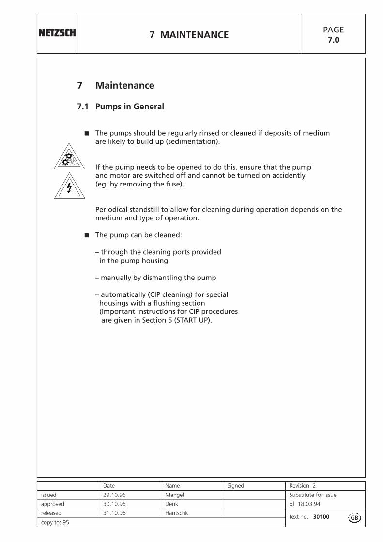
� The pumps should be regularly rinsed or cleaned if deposits of medium are likely to build up (sedimentation).
If the pump needs to be opened to do this, ensure that the pumpand motor are switched off and cannot be turned on accidently(eg. by removing the fuse).
Periodical standstill to allow for cleaning during operation depends on themedium and type of operation.
� The pump can be cleaned:
– through the cleaning ports provided in the pump housing
– manually by dismantling the pump
– automatically (CIP cleaning) for special housings with a flushing section (important instructions for CIP procedures are given in Section 5 (START UP).
GB


7 MAINTENANCE PAGE7.1
Date Name Signed Revision: 3
issued 10.09.09 Marchionini Substitute for issue
approved 10.09.09 Denk of 09.12.94
released 10.09.09 Denktext no. 30100
copy to:
7.2 Lubrication
The NEMO® pump does not require frequent lubrication.
� Maintenance of the drive should be carried out accordingto the drive manufacturers instructions.
� Maintenance– where no manufacturers instructions are available and– when normal conditions of use exist:
– Strip down the drive unit– Remove the bearings– Clean all parts– Renew the lubricant
every 5000 operating hours or at least every two years.
Special lubricants are often specified for mechanically controlled variable speed drives.It is therefore important to follow the drive manufacturersmaintenance instructions.
Pump model with “mechanical seals” (sectional drawing W251.000):
The lubricating should be done:
� when putting into operation
� after every 350 hours of operation
� before and after operation interruptions of 6 - 8 weeks.
GB

Continued Page 7.2R
Date Name Signed Revision:
issued 19.12.05 Mangel Substitute for issue
approved 20.12.05 Denk of
released 20.12.05 Denktext no. 30100
copy to:
7 MAINTENANCE PAGE7.2
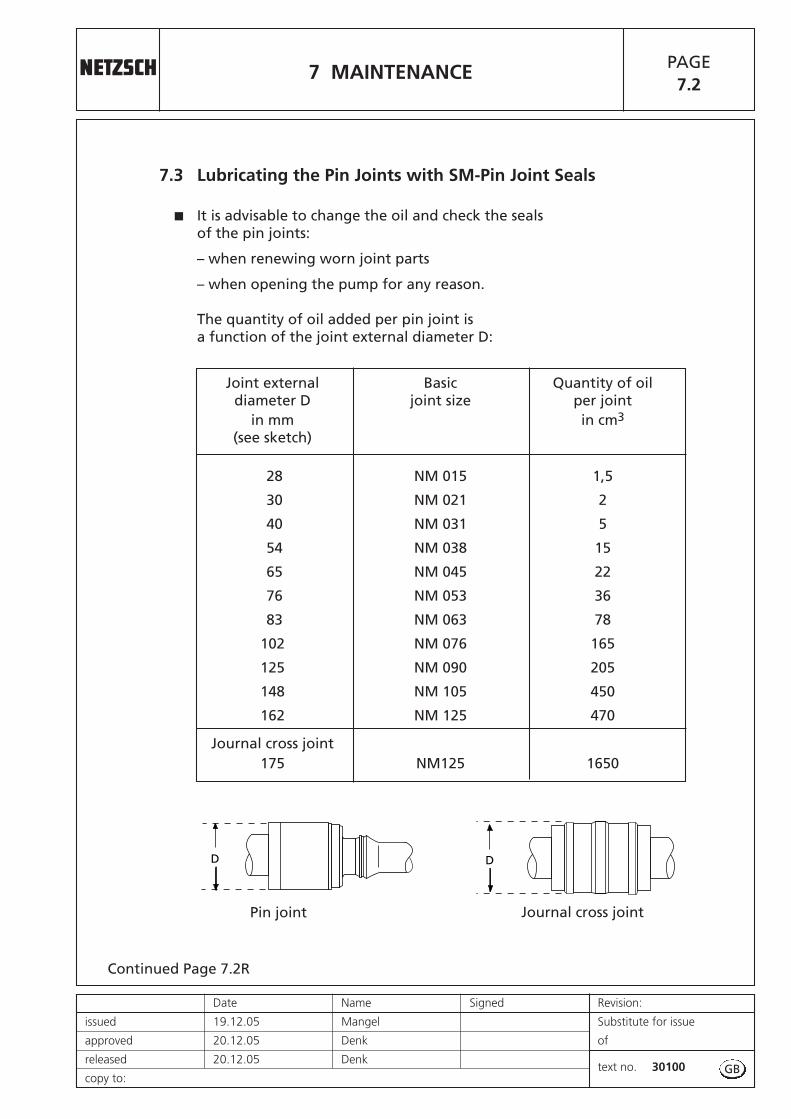
7.3 Lubricating the Pin Joints with SM-Pin Joint Seals
� It is advisable to change the oil and check the seals of the pin joints:
– when renewing worn joint parts
– when opening the pump for any reason.
The quantity of oil added per pin joint isa function of the joint external diameter D:
GB
Joint external Basic Quantity of oildiameter D joint size per joint
in mm in cm3
(see sketch)
28 NM 015 1,5
30 NM 021 2
40 NM 031 5
54 NM 038 15
65 NM 045 22
76 NM 053 36
83 NM 063 78
102 NM 076 165
125 NM 090 205
148 NM 105 450
162 NM 125 470
Journal cross joint175 NM125 1650
D D
Journal cross jointPin joint
7 MAINTENANCEPAGE7.2R
Revision: Date Name Signed
Substitute for issue issued 23.06.03 Mangel
of approved 24.06.03 Denk
text no. 30100released 24.06.03 Denk
copy to: 95
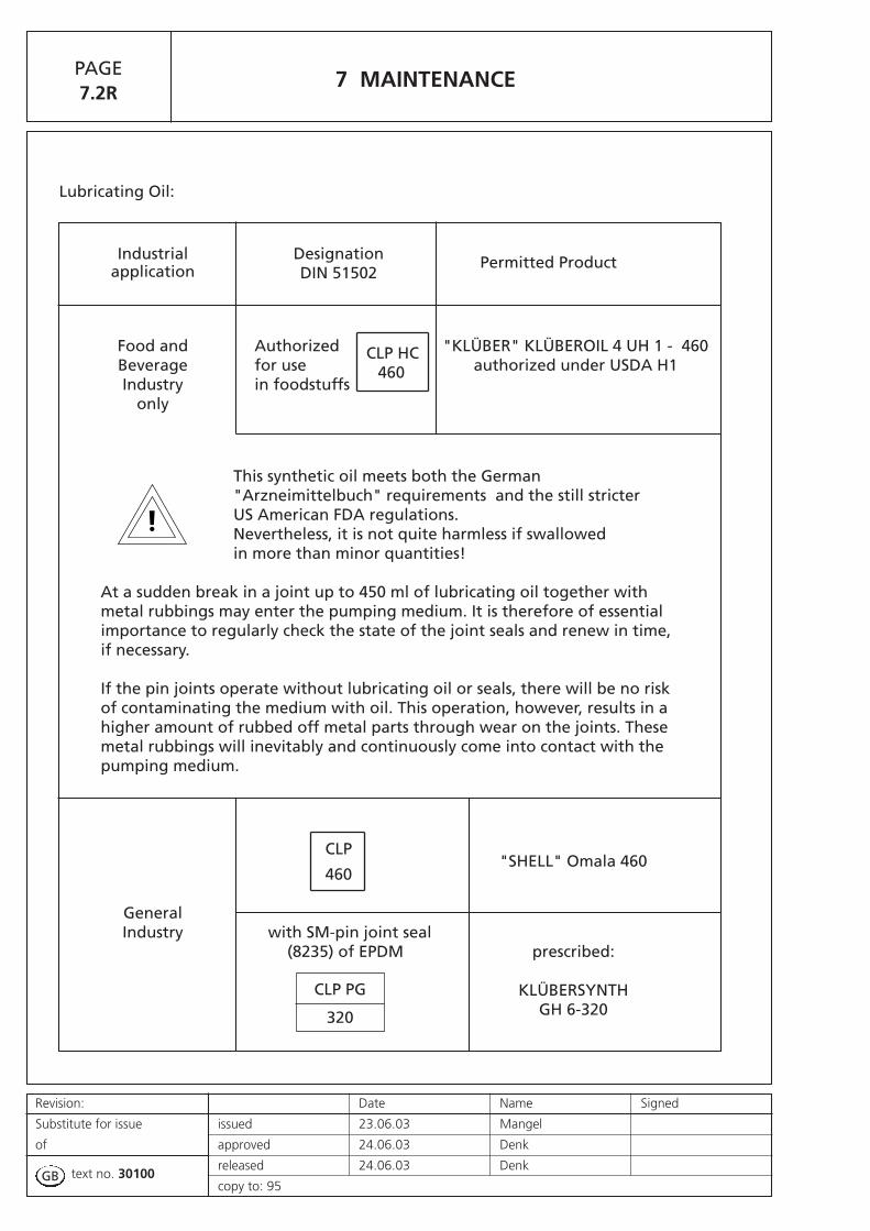
Lubricating Oil:
GB
Industrial Designation Permitted Productapplication DIN 51502
Food and Authorized CLP HC "KLÜBER" KLÜBEROIL 4 UH 1 - 460Beverage for use 460 authorized under USDA H1Industry in foodstuffs
only
This synthetic oil meets both the German "Arzneimittelbuch" requirements and the still stricter US American FDA regulations. Nevertheless, it is not quite harmless if swallowed in more than minor quantities!
At a sudden break in a joint up to 450 ml of lubricating oil together with metal rubbings may enter the pumping medium. It is therefore of essential importance to regularly check the state of the joint seals and renew in time, if necessary.
If the pin joints operate without lubricating oil or seals, there will be no risk of contaminating the medium with oil. This operation, however, results in a higher amount of rubbed off metal parts through wear on the joints. These metal rubbings will inevitably and continuously come into contact with the pumping medium.
CLP
460"SHELL" Omala 460
General Industry with SM-pin joint seal
(8235) of EPDM prescribed:
KLÜBERSYNTHGH 6-320
CLP PG
320

Date Name Signed Revision: 2
issued 06.02.95 Mangel Substitute for issue
approved 07.02.95 Eitler of 18.03.94
released 08.02.95 Hantschktext no. 30100
copy to: 95
Continued Page 7.3R
7 MAINTENANCE PAGE7.3
7.4 Shaft Sealing through Stuffing Box
7.4.1 Putting Into Operation
Before operation, it should be found out by visual check or on the order confirmation whether the stuffing box housing is fitted with buffer fluid connections and equipped with a buffer ring (7050). With a buffer ring (7050) fitted between the packing rings and suitable connection bores provided in the stuffing box housing, it will be possible to proceed as follows:
a) Adding a clear liquid as buffer mediumunder slight excess pressure. This applies for dirty or dangerous media or for the exclusion of air at suction operation of the pump.
b) Adding a lubricant.
c) Adding a cooling or warming fluidor steam.
For a) and b) it is usually enough to just add the buffer medium. However, the second connection in the stuffing box housing should then be closed off.For c) it is necessary to feed in and carry away the medium via the two connection bores.
If for a compelling reason a stuffing box with buffer ring has to be operated without a medium as described in a) to c), it is essential toensure that all the connection bores in the stuffing box are tightened with plugs (please note the material resistance!). This is especially important when the pump has to prime as otherwise air will be drawn in through the bores.
Stuffing box packings have the function of minimizing, but not totally eliminating the escape of medium. A lubricant or liquid coating is required to reduce the shaft wear to a minimum and dissipate the heat caused by friction.
Avoid touching the rotating shaft.Risk of injury where the pin is visible!
The stuffing box gland should therefore be tightened only gently by hand prior to putting into operation. A high initial rate of leakage should be permitted, particularly with PTFE or PTFE–impregnated packings;50 – 200 drops/min depending on the
medium and sliding velocity.
7050
GB
Continued Page 7.4
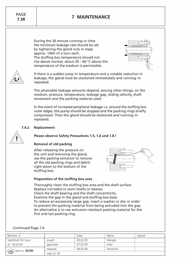
During the 30 minute running–in time the minimum leakage rate should be set by tightening the gland nuts in steps approx. 1/6th of a turn each. The stuffing box temperature should not rise above normal, about 20 – 60 °C above the temperature of the medium is permissible.
If there is a sudden jump in temperature and a notable reduction in leakage, the gland must be slackened immediately and running–in repeated.
The attainable leakage amounts depend, among other things, on the medium, pressure, temperature, leakage gap, sliding velocity, shaft movement and the packing material used.
In the event of increased peripheral leakage i.e. around the stuffing boxouter edges, the pump should be stopped and the packing rings briefly compressed. Then the gland should be slackened and running–in repeated.
7.4.2 Replacement
Please observe Safety Precautions 1.5, 1.6 und 1.8 !
Removal of old packing
After releasing the pressure on the unit and removing the gland, use the packing extractor to remove all the old packing rings and debris right down to the bottom of the stuffing box.
Preparation of the stuffing box area
Thoroughly clean the stuffing box area and the shaft surface. Replace corroded or worn shafts or sleeves. Check the shaft bearing and the shaft concentricity. Examine the gap in the gland and stuffing box base. To reduce an excessively large gap, insert a washer or disc in order to prevent the packing material from being extruded into the gap. An alternative is to use extrusion–resistant packing material for the first and last packing ring.
Revision: 2 Date Name Signed
Substitute for issue issued 06.02.95 Mangel
of 18.03.94 approved 07.02.95 Eitler
text no. 30100released 08.02.95 Hantschk
copy to: 95
7 MAINTENANCEPAGE7.3R
GB
Continued Page 7.4 R
Selection of grade and size of packing
Before installing the packing, check once again whether you have chosen a packing suitable for the operating conditions required.
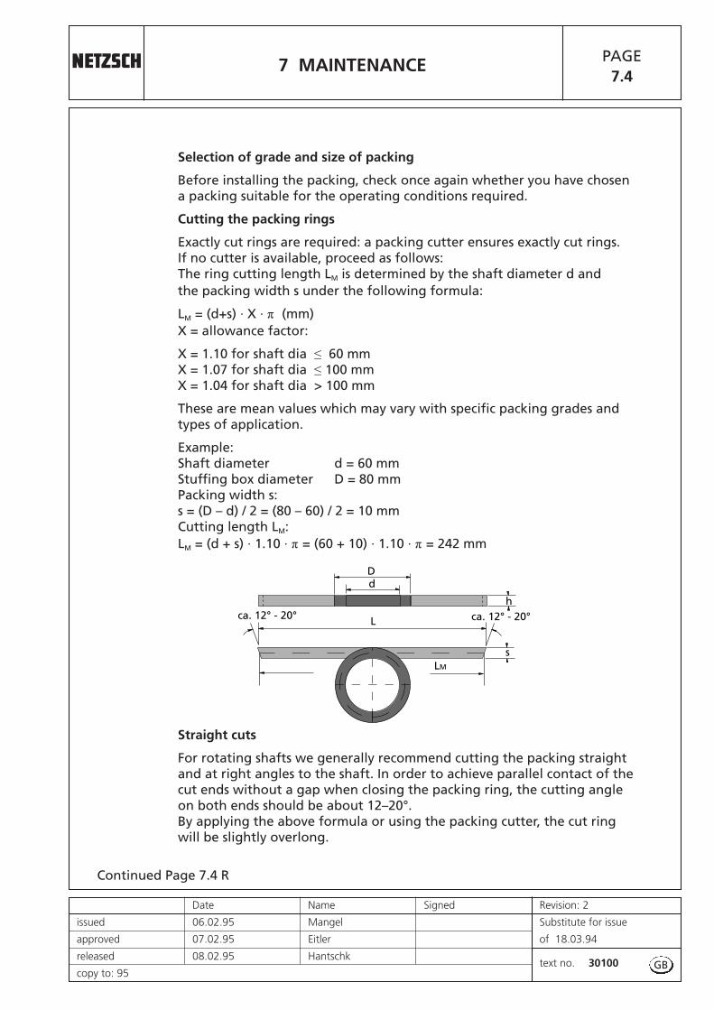
Cutting the packing rings
Exactly cut rings are required: a packing cutter ensures exactly cut rings.If no cutter is available, proceed as follows:The ring cutting length LM is determined by the shaft diameter d and the packing width s under the following formula:
LM = (d+s) · X · π (mm)X = allowance factor:
X = 1.10 for shaft dia ≤ 60 mmX = 1.07 for shaft dia ≤ 100 mmX = 1.04 for shaft dia > 100 mm
These are mean values which may vary with specific packing grades andtypes of application.
Example:Shaft diameter d = 60 mmStuffing box diameter D = 80 mmPacking width s:s = (D – d) / 2 = (80 – 60) / 2 = 10 mmCutting length LM:LM = (d + s) · 1.10 · π = (60 + 10) · 1.10 · π = 242 mm
Straight cuts
For rotating shafts we generally recommend cutting the packing straight and at right angles to the shaft. In order to achieve parallel contact of the cut ends without a gap when closing the packing ring, the cutting angle on both ends should be about 12–20°.By applying the above formula or using the packing cutter, the cut ring will be slightly overlong.
7 MAINTENANCE PAGE7.4
Date Name Signed Revision: 2
issued 06.02.95 Mangel Substitute for issue
approved 07.02.95 Eitler of 18.03.94
released 08.02.95 Hantschktext no. 30100
copy to: 95
dD
Lca. 12° - 20° ca. 12° - 20°
LM
s
h
GB
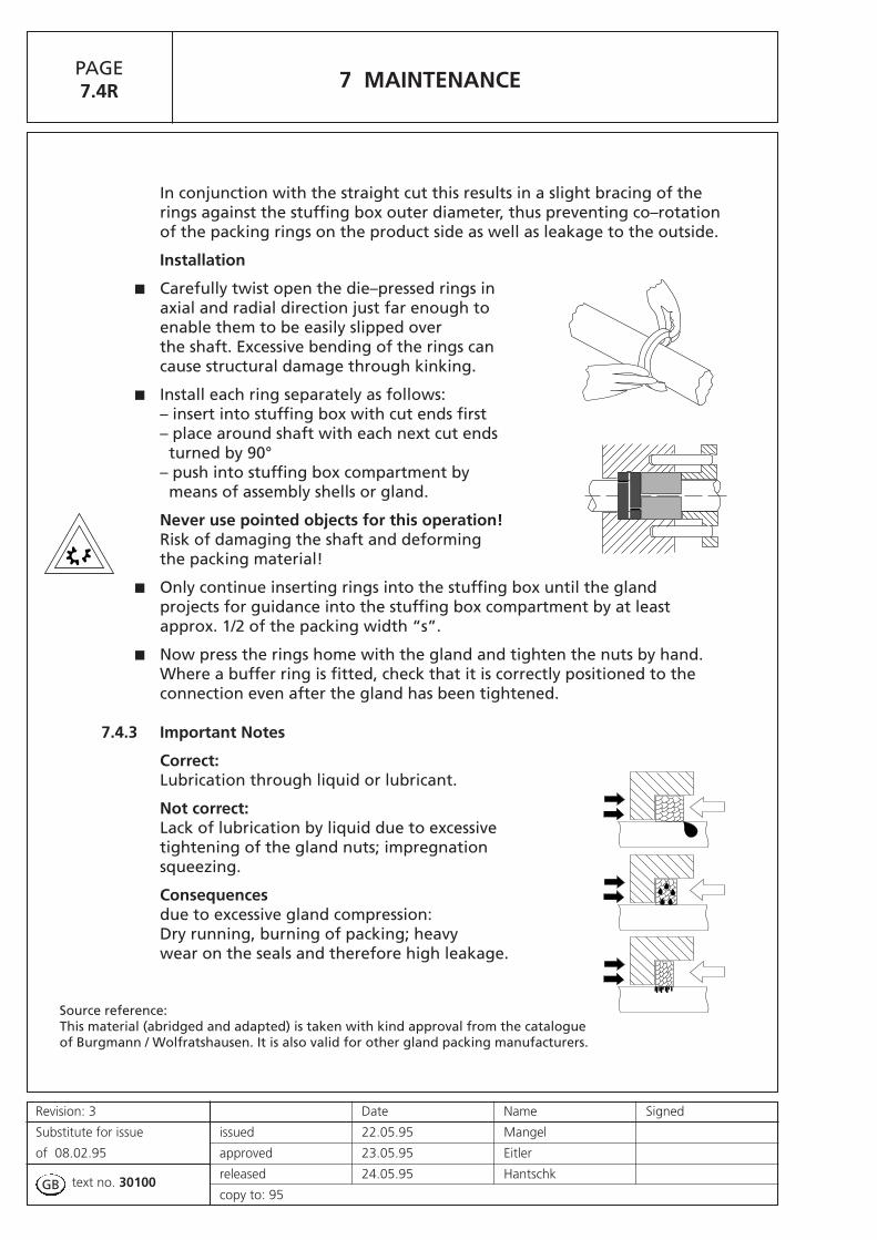
In conjunction with the straight cut this results in a slight bracing of the rings against the stuffing box outer diameter, thus preventing co–rotation of the packing rings on the product side as well as leakage to the outside.
Installation
� Carefully twist open the die–pressed rings in axial and radial direction just far enough to enable them to be easily slipped overthe shaft. Excessive bending of the rings can cause structural damage through kinking.
� Install each ring separately as follows: – insert into stuffing box with cut ends first– place around shaft with each next cut endsturned by 90°
– push into stuffing box compartment by means of assembly shells or gland.
Never use pointed objects for this operation!Risk of damaging the shaft and deforming the packing material!
� Only continue inserting rings into the stuffing box until the glandprojects for guidance into the stuffing box compartment by at least approx. 1/2 of the packing width “s”.
� Now press the rings home with the gland and tighten the nuts by hand.Where a buffer ring is fitted, check that it is correctly positioned to theconnection even after the gland has been tightened.
7.4.3 Important Notes
Correct:Lubrication through liquid or lubricant.
Not correct:Lack of lubrication by liquid due to excessive tightening of the gland nuts; impregnation squeezing.
Consequencesdue to excessive gland compression:Dry running, burning of packing; heavywear on the seals and therefore high leakage.
Source reference: This material (abridged and adapted) is taken with kind approval from the catalogue of Burgmann / Wolfratshausen. It is also valid for other gland packing manufacturers.
7 MAINTENANCEPAGE7.4R
Revision: 3 Date Name Signed
Substitute for issue issued 22.05.95 Mangel
of 08.02.95 approved 23.05.95 Eitler
text no. 30100released 24.05.95 Hantschk
copy to: 95GB

Continued Page 7.5R
7.5 Shaft Sealing through Single Mechanical Seal
There are various constructions of mechanical seals. Especially advantageous is the use of standard mechanical seals according to DIN 24960. These seals have regardless of their brand the same fitting dimensions which makes them interchangeable.Mechanical seals with a coil spring can only be used for pumps which are run in one direction of rotation.
� The seal specification of a NEMO® pump is recordedon the order confirmation sheet.
� Pumps fitted with direction dependent seals should never be run in the opposite direction ofthe rotation arrow.
� If excessive leakages occur the spring tension and the seal surfaces should be checked, and the seal be replaced, if necessary.
Single mechanical seals usually work without any additionalequipment. Their application range can be increased by operatingthem with a rinsing or cooling system.
a) Quench, in accordance with ISO 5199, Appendix E, Plan Nos. 08, 09, 10 or 13 or API 610, Appendix D, Plan No. 62.
Quench is the designation commonly used in sealing engineering for an arrangement that applies a non pressurized external fluid to the atmospheric side of a mechanical seal. The quench is used when
– a single mechanical seal will not work or only to a limited extent without auxiliary measures or
– a double mechanical seal with pressurized buffer fluid is not necessary.
Recommended for the following applications:
– Low temperature (danger of freezing)
– Operation in a vacuum (dry running)
– Media which must beisolated from the atmos-phere (eg. due to build upof solid deposits or because of less severe damage to the environment, like smell).
7 MAINTENANCE PAGE7.5
Date Name Signed Revision:
issued 23.06.03 Mangel Substitute for issue
approved 24.06.03 Denk of
released 24.06.03 Denktext no. 30100
copy to: GB
1
3
4
2
Product
Atmos-phere

Leakages will be transportet away by the quenching liquid.In vacuum operation dry running of the seals is avoided.
No pressure higher than that of the pumped medium in front of themechanical seal is allowed to build up in the quenching area (1) behind the mechanical seal. Otherwise the counter ring will be pushed out of the housing. Free discharge from (2) is necessary!
Closing off the quenching area from the atmosphere can be done in three ways:
1. In the case that high emission levels can be tolerated:Through a throttle bush (4). Cooling liquid not permanently used, only released from time to time.
2. In the case that medium emission levels can be tolerated:By a radial shaft seal ring (3). Permanent radial shaft seal lubrication through quenching liquid is necessary.
b) Top lubrication
Attention: For vertically installed pumpswith overhead drive as type NT:
On initial start-up the mechanical seal has not come in contact with the medium. It runs therefore dry for a short period of time until the air is displaced from the pump housing.
� On first start–up and if stood idle for longer periods lubricate the mechanical seal before switching on the pump.
� Apply water, glycerine or oil depending on their compatibility with the pumping medium and the elastomer of the mechanical seal.
� Fill the quench cup of the mechanical seal housing.
7 MAINTENANCEPAGE7.5R
Revision: Date Name Signed
Substitute for issue issued 23.06.03 Mangel
of approved 24.06.03 Denk
text no. 30100released 24.06.03 Denk
copy to: 95GB
Continued Page 8.0R
8 TROUBLE-SHOOTING AND REMEDYING PAGE8.0
Date Name Signed Revision: 2
issued 20.09.95 Mangel Substitute for issue
approved 21.09.95 Eitler of 18.03.94
released 22.09.95 Hantschktext no. 30100
copy to: 95
8 Trouble-Shooting and Remedying
8.1 Trouble Chart
The chart overleaf lists possible problems
– the type– the likely reason / cause– the remedy.
� A problem may have various causes: Several boxes in the verticalcolumn are marked with a cross.
� A reason / cause may result in various problems:Several boxes in the horizontal column are marked with a cross.
8.2 How do you trace the kind of problem to find the possible cause ?
– The column describing a possible problem shows one or severalboxes marked with a cross.
– On the corresponding lines you will find the possible reasons / cause and some hints how to handle the problem .Thus the actual cause of the problem can be narrowed down andeventually detected.
– If you find further cross-marked boxes on one of the linesand should there appear corresponding problems as well,then the likely cause of the problem has been detected.
� The table helps in finding the root of the problem and will give you the remedy if it is straight forward. For more complicated problems the manufacturer has to be consulted.
GB

The
pu
mp
is n
o lo
ng
er s
tart
ing
The
pu
mp
is n
o lo
ng
er s
uck
ing
The
pu
mp
ed m
ediu
m is
to
o li
ttle
The
pre
ssu
re is
to
o lo
w
The
pu
mp
ed m
ediu
m is
un
stab
le
The
pu
mp
is r
un
nin
g lo
ud
ly
The
pu
mp
is s
tuck
The
dri
ve is
ove
rlo
aded
The
stat
or
life
tim
e is
to
o s
ho
rt
The
roto
r lif
e ti
me
is t
oo
sh
ort
The
shaf
t se
al is
leak
ing
Possible Problems
In new pumps or stators : the static friction is too great.
The pump electrical equipment is not compatible with the electrical supply.
There are foreign bodies in the pump.
The stator has swollen, the elastomer is not compatible with the medium.
The liquid medium sediments or hardens when left to stand.
The suction pipe is leaking.
The rpm is too low.
The suction is too great or pressure too low (cavitation).
The stator is worn out, or temperature of liquid is too low.
The rotor is worn out.
The pump and drive are not axially aligned.
The roller bearings are destroyed.
The viscosity is too high.
The stuffing box is incorrectly tightened.
Mechanical seal : rotation is incorrect.
Mechanical seal : elastomers damaged, swollen or brittle.
The pressure is too high.
The temperature of the liquid medium is too high, the stator is too ductile.
The solids content of the medium is too high and leads to blockages.
There is air in the suction pipe.
The shaft seal is leaking.
With reduced diameter rotors : operating temperature has not been reached.
The pump is running dry.
The stator material is brittle.
The joints are worn out.
The elastic element of the coupling is worn out.
The rpm is too high.
The specific weight of the medium is too high.
The packing is not suited to the liquid medium.
Mechanical seal : mechanical seal and mating ring have failed.
Possible Causes ( Remedy overleaf)
The NEMO®-pump is a well established productwhich was thoroughly tested before leaving thefactory. If you use the pump in keeping with yourOrder Specification and treat it in accordance withour Operating and Maintenance Instructions, itwill run satisfactorily for a long period of time.
Revision: Date Name Signed
Substitute for issue issued 20.09.95 Mangel
of approved 21.09.95 Eitler
text no. 30100released 22.09.95 Hantschk
copy to:GB
Replace elastomers. Check whether the liquid medium agrees with order details, if necessary change material.
8 TROUBLE-SHOOTING AND REMEDYING PAGE8.1
Date Name Signed Revision: 3
issued 18.10.95 Mangel Substitute for issue
approved 19.10.95 Hantschk of 22.09.95
released 20.10.95 Hantschktext no. 30100
copy to: 95
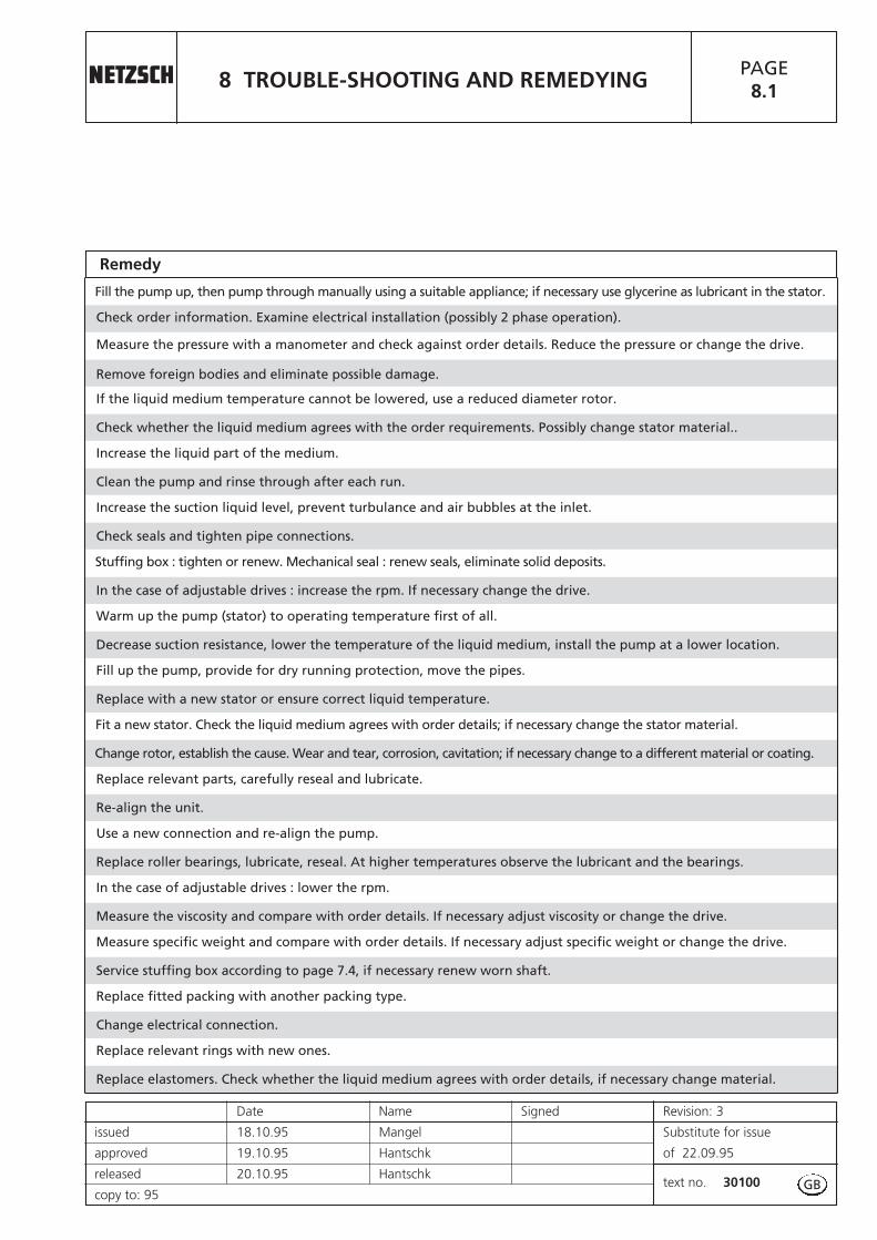
Fill the pump up, then pump through manually using a suitable appliance; if necessary use glycerine as lubricant in the stator.
Check order information. Examine electrical installation (possibly 2 phase operation).
Remove foreign bodies and eliminate possible damage.
Check whether the liquid medium agrees with the order requirements. Possibly change stator material..
Clean the pump and rinse through after each run.
Check seals and tighten pipe connections.
In the case of adjustable drives : increase the rpm. If necessary change the drive.
Decrease suction resistance, lower the temperature of the liquid medium, install the pump at a lower location.
Replace with a new stator or ensure correct liquid temperature.
Change rotor, establish the cause. Wear and tear, corrosion, cavitation; if necessary change to a different material or coating.
Re-align the unit.
Replace roller bearings, lubricate, reseal. At higher temperatures observe the lubricant and the bearings.
Measure the viscosity and compare with order details. If necessary adjust viscosity or change the drive.
Service stuffing box according to page 7.4, if necessary renew worn shaft.
Change electrical connection.
Measure the pressure with a manometer and check against order details. Reduce the pressure or change the drive.
If the liquid medium temperature cannot be lowered, use a reduced diameter rotor.
Increase the liquid part of the medium.
Increase the suction liquid level, prevent turbulance and air bubbles at the inlet.
Stuffing box : tighten or renew. Mechanical seal : renew seals, eliminate solid deposits.
Warm up the pump (stator) to operating temperature first of all.
Fill up the pump, provide for dry running protection, move the pipes.
Fit a new stator. Check the liquid medium agrees with order details; if necessary change the stator material.
Replace relevant parts, carefully reseal and lubricate.
Use a new connection and re-align the pump.
In the case of adjustable drives : lower the rpm.
Measure specific weight and compare with order details. If necessary adjust specific weight or change the drive.
Replace fitted packing with another packing type.
Replace relevant rings with new ones.
Remedy
GB

Continued Page 9.0R
9 DISMANTLING AND ASSEMBLYOF THE PUMP HOUSING
PAGE9.0
Date Name Signed Revision:
issued 24.06.03 Mangel Substitute for issue
approved 25.06.03 Denk of
released 25.06.03 Denktext no. 30100
copy to:
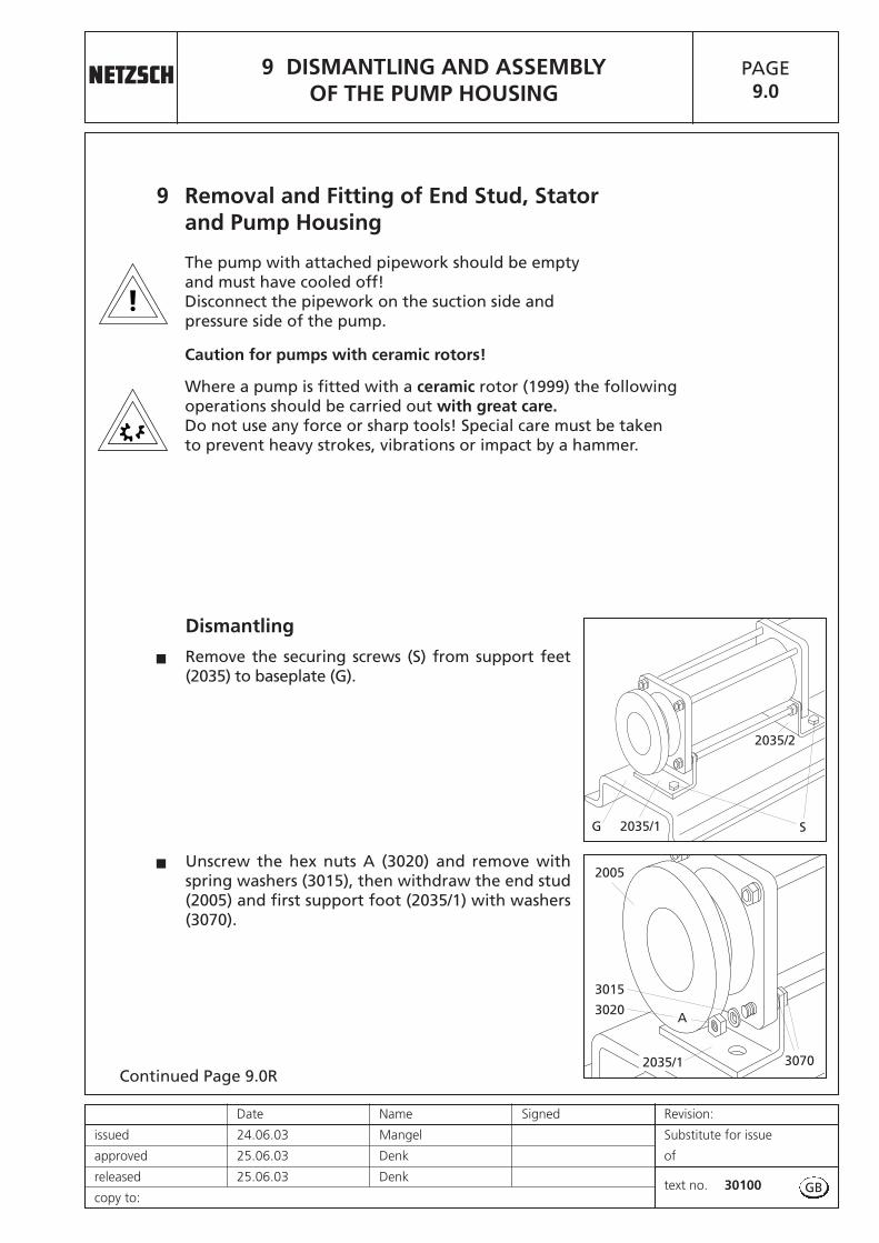
9 Removal and Fitting of End Stud, Stator and Pump Housing
The pump with attached pipework should be empty and must have cooled off!Disconnect the pipework on the suction side and pressure side of the pump.
Caution for pumps with ceramic rotors!
Where a pump is fitted with a ceramic rotor (1999) the following operations should be carried out with great care.Do not use any force or sharp tools! Special care must be taken to prevent heavy strokes, vibrations or impact by a hammer.
2035/1G
2035/2
2035/1
2005
3020
3015
A
3070
Dismantling
Remove the securing screws (S) from support feet(2035) to baseplate (G).
Unscrew the hex nuts A (3020) and remove withspring washers (3015), then withdraw the end stud(2005) and first support foot (2035/1) with washers(3070).
�
�
S
GB

9 DISMANTLING AND ASSEMBLYOF THE PUMP HOUSING
Continued Page 9.1
PAGE9.0R
Revision: Date Name Signed
Substitute for issue issued 24.06.03 Mangel
of approved 25.06.03 Denk
text no. 30100released 25.06.03 Denk
copy to:
3010
3020
2010
B
Support pump housing (2010) and stator (3005) withwooden blocks.
Loosen the hex nuts B (3020), where fitted, andremove the thru bolts (3010).
�
Where fitted, remove the second support foot(2035/2) and the washers (3070).
�
�
Caution for pumps with ceramic rotors!
When the stator (3005) is removed from the ceramic rotor (1999), the stator mustbe supported to prevent it from suddenly tilting away downwards. The sameapplies to the rotor (1999) as soon as it is disengaged from the stator (3005). Removing the stator (3005) from the ceramic rotor (1999) is easier by using anextractor. This should be done slowly and with care in a rotating movement. When sliding pump housing (2010) over ceramic rotor (1999), both coupling rod(1998) and rotor (1999) should be lifted as the ceramic rotor (1999) must notknock onto the pump housing (2010).
GB
2010 1999 19983005
2035/2
3070
3005
Continued Page 9.1R
9 DISMANTLING AND ASSEMBLYOF THE PUMP HOUSING
PAGE9.1
Date Name Signed Revision:
issued 24.06.03 Mangel Substitute for issue
approved 25.06.03 Denk of
released 25.06.03 Denktext no. 30100
copy to:
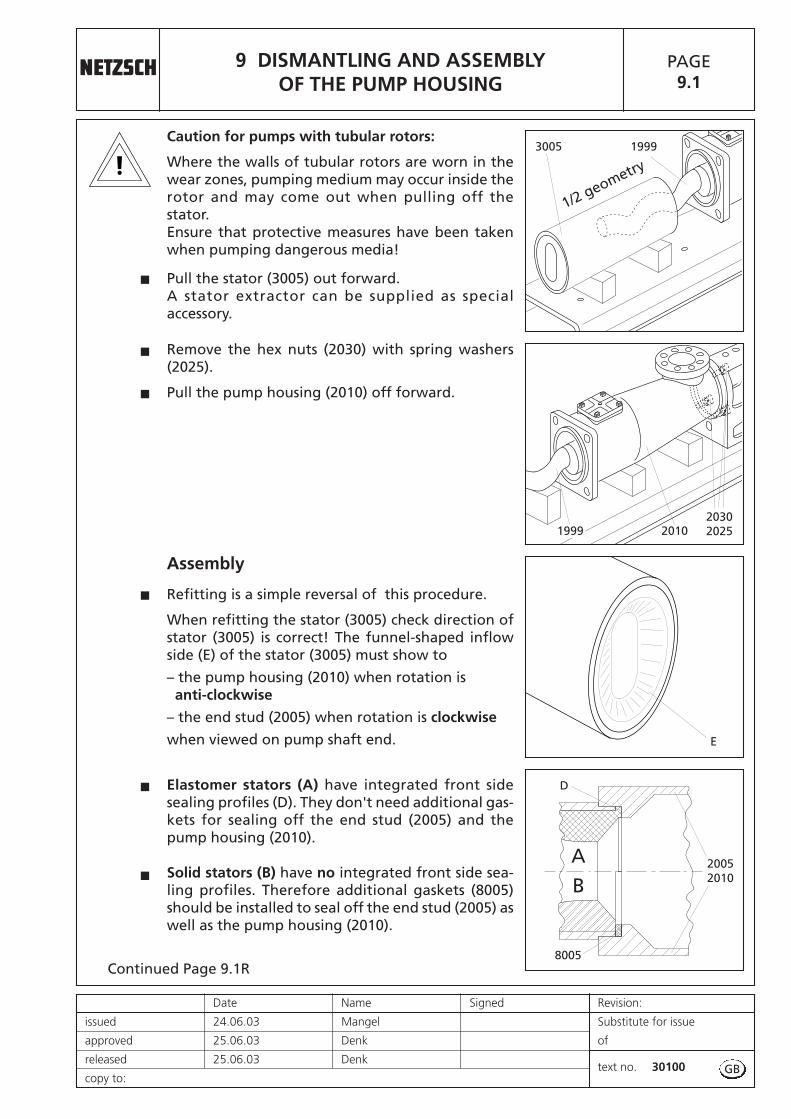
Remove the hex nuts (2030) with spring washers(2025).
Pull the pump housing (2010) off forward.�
�
3005 1999Caution for pumps with tubular rotors:
Where the walls of tubular rotors are worn in thewear zones, pumping medium may occur inside therotor and may come out when pulling off thestator. Ensure that protective measures have been takenwhen pumping dangerous media!
Pull the stator (3005) out forward.A stator extractor can be supplied as specialaccessory.
�
1/2 geometry
GB
2010199920302025
E
A
B
D
8005
20052010
Assembly
Refitting is a simple reversal of this procedure.
When refitting the stator (3005) check direction ofstator (3005) is correct! The funnel-shaped inflowside (E) of the stator (3005) must show to
– the pump housing (2010) when rotation is anti-clockwise
– the end stud (2005) when rotation is clockwise
when viewed on pump shaft end.
Elastomer stators (A) have integrated front sidesealing profiles (D). They don't need additional gas-kets for sealing off the end stud (2005) and thepump housing (2010).
Solid stators (B) have no integrated front side sea-ling profiles. Therefore additional gaskets (8005)should be installed to seal off the end stud (2005) aswell as the pump housing (2010).
�
�
�
9 DISMANTLING AND ASSEMBLYOF THE PUMP HOUSING
PAGE9.1R
Revision: Date Name Signed
Substitute for issue issued 24.06.03 Mangel
of approved 25.06.03 Denk
text no. 30100released 25.06.03 Denk
copy to:
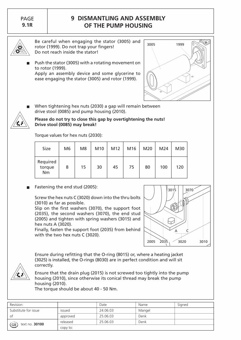
Be careful when engaging the stator (3005) androtor (1999). Do not trap your fingers! Do not reach inside the stator!
Push the stator (3005) with a rotating movement onto rotor (1999). Apply an assembly device and some glycerine toease engaging the stator (3005) and rotor (1999).
�
3005 1999
GB
Fastening the end stud (2005):
Screw the hex nuts C (3020) down into the thru bolts(3010) as far as possible.Slip on the first washers (3070), the support foot(2035), the second washers (3070), the end stud(2005) and tighten with spring washers (3015) andhex nuts A (3020).Finally, fasten the support foot (2035) from behindwith the two hex nuts C (3020).
When tightening hex nuts (2030) a gap will remain between drive stool (0085) and pump housing (2010).
Please do not try to close this gap by overtightening the nuts! Drive stool (0085) may break!
Torque values for hex nuts (2030):
�
�
2005 30103020
3015 3070
2035
A C
Ensure during refitting that the O-ring (8015) or, where a heating jacket (3025) is installed, the O-rings (8030) are in perfect condition and will sit correctly.
Ensure that the drain plug (2015) is not screwed too tightly into the pump housing (2010), since otherwise its conical thread may break the pump housing (2010). The torque should be about 40 - 50 Nm.
Size M6 M8 M10 M12 M16 M20 M24 M30
Requiredtorque 8 15 30 45 75 80 100 120Nm

continued on page 9.2R
9 DISMANTLING AND ASSEMBLYOF THE PUMP HOUSING
PAGE9.2
Date Name Signed Revision: 1
issued 22.10.09 Marchionini Substitute for issueof 27.04.07approved 22.10.09 Kamal
released 22.10.09 Kamal text no.09101-1/2copy to:
9.1 Assembly and disassembly of the iFD-Stator®
iFD-Stator® - new stator technology
The iFD-Stator® (ref. 3005) is a patented design and comprises the stator (ref. 3000),the stator housing (ref. 3001) and the stator clamping sleeve (ref. 3002)..
The iFD-Stator® is maintenance free.The elastomer (ref. 3000) is simply replaced when worn: the stator housing (ref. 3001)and clamping sleeve (ref. 3002) are reused.
This reduces your purchasing quantities and creates less waste. This solution alsomeans that the difficult disposal of composite materials is no longer an issue: both toyour advantage and that of the environment.
Recommendations for reordering the iFD-Replacement-Stator® (ref. 3000):The iFD-Replacement-Stator® (ref. 3000) is simply ordered using the part numberfound on the front page of your Operating and Maintenance Manual as well as on thepump identification plate, together with the parts list reference no. 3000.
iFD-Stator® replacement:a powerful connection and easy to use
Step 1: Loosen the thru bolts
Support the pump housing (ref. 2010) and stator(ref. 3005) with wooden blocks before removingthe thru bolts (ref. 3010).
9 DISMANTLING AND ASSEMBLYOF THE PUMP HOUSING
continued on page 9.3
PAGE9.2R
Revision: 1 Date Name Signed
Substitute for issueof 27-04.07
issued 22.10.09 Marchionini
approved 22.10.09 Kamal
text no.R 09101-1/2
released 22.10.09 Kamal
copy to:
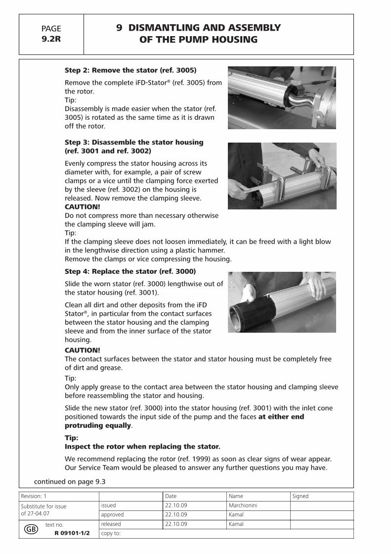
Step 2: Remove the stator (ref. 3005)
Remove the complete iFD-Stator® (ref. 3005) fromthe rotor.Tip:Disassembly is made easier when the stator (ref.3005) is rotated as the same time as it is drawnoff the rotor.
Step 3: Disassemble the stator housing(ref. 3001 and ref. 3002)
Evenly compress the stator housing across itsdiameter with, for example, a pair of screwclamps or a vice until the clamping force exertedby the sleeve (ref. 3002) on the housing isreleased. Now remove the clamping sleeve.CAUTION!Do not compress more than necessary otherwisethe clamping sleeve will jam.Tip:If the clamping sleeve does not loosen immediately, it can be freed with a light blowin the lengthwise direction using a plastic hammer.Remove the clamps or vice compressing the housing.
Step 4: Replace the stator (ref. 3000)
Slide the worn stator (ref. 3000) lengthwise out ofthe stator housing (ref. 3001).
Clean all dirt and other deposits from the iFDStator®, in particular from the contact surfacesbetween the stator housing and the clampingsleeve and from the inner surface of the statorhousing.CAUTION!The contact surfaces between the stator and stator housing must be completely freeof dirt and grease.Tip:Only apply grease to the contact area between the stator housing and clamping sleevebefore reassembling the stator and housing.
Slide the new stator (ref. 3000) into the stator housing (ref. 3001) with the inlet conepositioned towards the input side of the pump and the faces at either endprotruding equally.
Tip:Inspect the rotor when replacing the stator.
We recommend replacing the rotor (ref. 1999) as soon as clear signs of wear appear.Our Service Team would be pleased to answer any further questions you may have.

9 DISMANTLING AND ASSEMBLYOF THE PUMP HOUSING
PAGE9.3
Date Name Signed Revision: 1
issued 22.10.09 Marchionini Substitute for issueof 27.04.07approved 22.10.09 Kamal
released 22.10.09 Kamal text no.09101-2/2copy to:
Step 5: Assemble the stator (ref. 3005)
To assemble the stator clamping sleeve (ref. 3002),reclamp the stator housing (ref. 3001) across itsdiameter and slightly compress the housing.CAUTION!Only compress the housing until the the clampingsleeve can be easily slid onto the housing.Close the housing by sliding the clamping sleeveover the housing guides - note that it should notbe necessary to use force to do this.Tip:It is recommended that the clamping sleeve, which is shorter than the housing, is slidon until it is sitting centrally on the housing.
Finally, release the housing from the clamps or vice.
CAUTION!Check that the stator is centrally positioned in the stator housing before releasing theclamps.
Step 6: Mount the stator on the pump(ref. 3005)
Slide the iFD-Stator® onto the rotor with the labelfacing upwards.The iFD-Stator® appears to be slightly oversizewhen it being assembled - allowing it to be easilyslid onto the rotor. This greatly simplifies statorreplacement and allows maintenance and down-times to be reduced to a minimum.Reinsert the thru bolts (ref. 3010) in the pump housing (ref. 2010) and reassemble theend studs (ref. 2005).Tighten all nuts.The axial compression of the whole iFD Stator® ensures that the optimal pre-stress isprovided for the rotor. At the same time the axial compression ensures the sealing ofthe housing ends.Tip:Record the replacement interval directly on the stator.The empty label fields on the stator housing are intended to be used to record, forexample, maintenance dates or rotor replacement intervals and can be filled in using astandard fibre-tip pen.Explosion protectionVDE-conform earthing must be provided for both housing parts (ref. 3001) and (ref.3002) when used in an explosion-protected area.
Stator-Protektor STP-2AConnection of the STP-2A is described in text no. 13105.

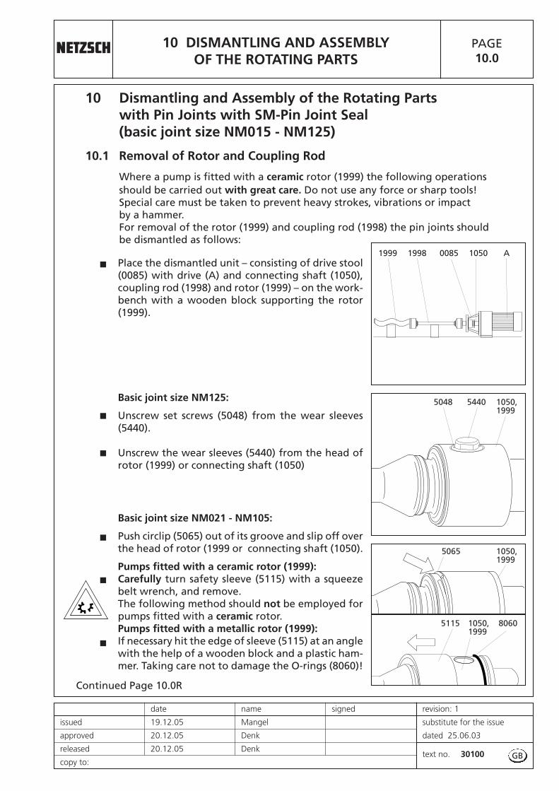
Continued Page 10.0R
10 DISMANTLING AND ASSEMBLYOF THE ROTATING PARTS
PAGE10.0
date name signed revision: 1
issued 19.12.05 Mangel substitute for the issue
approved 20.12.05 Denk dated 25.06.03
released 20.12.05 Denktext no. 30100
copy to:
10 Dismantling and Assembly of the Rotating Partswith Pin Joints with SM-Pin Joint Seal (basic joint size NM015 - NM125)
10.1 Removal of Rotor and Coupling Rod
Where a pump is fitted with a ceramic rotor (1999) the following operations should be carried out with great care. Do not use any force or sharp tools! Special care must be taken to prevent heavy strokes, vibrations or impact by a hammer. For removal of the rotor (1999) and coupling rod (1998) the pin joints should be dismantled as follows:
Place the dismantled unit – consisting of drive stool(0085) with drive (A) and connecting shaft (1050),coupling rod (1998) and rotor (1999) – on the work-bench with a wooden block supporting the rotor(1999).
Basic joint size NM125:
Unscrew set screws (5048) from the wear sleeves(5440).
Unscrew the wear sleeves (5440) from the head ofrotor (1999) or connecting shaft (1050)
Basic joint size NM021 - NM105:
Push circlip (5065) out of its groove and slip off overthe head of rotor (1999 or connecting shaft (1050).
Pumps fitted with a ceramic rotor (1999): Carefully turn safety sleeve (5115) with a squeezebelt wrench, and remove. The following method should not be employed forpumps fitted with a ceramic rotor. Pumps fitted with a metallic rotor (1999): If necessary hit the edge of sleeve (5115) at an anglewith the help of a wooden block and a plastic ham-mer. Taking care not to damage the O-rings (8060)!
�
�
�
�
�
�
GB
1999 10500085 A1998
5065 1050, 1999
5115 1050, 1999
8060
54405048 1050, 1999

Continued Page 10.1
10 DISMANTLING AND ASSEMBLYOF THE ROTATING PARTS
PAGE10.0R
revision: 1 date name signed
substitute for the issue issued 19.12.05 Mangel
dated 25.06.03 approved 20.12.05 Denk
text no. 30100released 20.12.05 Denk
copy to: 95
Basic joint size NM021 - NM125:
Press the pin (5075) out of the head of rotor (1999)or connecting shaft (1050). If necessary use a ham-mer and a thin cylindrical pin (DIN 6450 C).Drain the oil into a receptacle.
Caution for pumps with ceramic rotors!
Where a pin (5075) may not come out easily, themetallic head of rotor (1999) should be supportedon wooden blocks. Then the pin (5075) can be dri-ven out with the help of a pin punch (DIN 6450 C).This should be done with care, holding the ceramicrotor with your hands. Please dispose of this oil in the proper manner.
Using a screwdriver, carefully lever the SM-pin jointseal (8235) out of the head of rotor (1999) or connec-ting shaft (1050).
Taking care not to damage the SM-pin joint seal(8235)!
Pull apart the rotor (1999)/ coupling rod (1998) /connecting shaft (1050) assembly. Remove the O-rings (8060).
Push the SM-pin joint seal (8235) towards the headof coupling rod (1998). In the narrow coupling rodsection press the clamp ring (5425) out of thegroove of the seal. Then slip the SM-pin joint seal(8235) and clamp ring (5425) off over the head of thecoupling rod (1998).
�
�
�
�
1998 8235 8060
10501999
10501999
5075
1998 806010501999
5425 8235 1998
GB

Continued Page 10.1R
10 DISMANTLING AND ASSEMBLYOF THE ROTATING PARTS
PAGE10.1
date name signed revision:
issued 24.06.03 Mangel substitute for the issue
approved 25.06.03 Denk dated
released 25.06.03 Denktext no. 30100
copy to:
10.2 Fitting the Rotor and Coupling Rod
For fitting the rotor (1999) with coupling rod (1998),the two pin joints should be assembled as follows:
Slip the clamp ring (5425) over the head of couplingrod (1998).
Push the SM-pin joint seal (8235) over the head ofcoupling rod (1998) towards its narrow section, theresqeezing the clamp ring (5425) into the groove ofthe SM-pin joint seal (8235).
Push the SM-pin joint seal (8235) with the correctlyplaced clamp ring (5425) up to the shoulder ofcoupling rod (1998).
5425
5425
1998
1998
8235
8235
8235
1998
�
�
�
GB

Continued Page 10.2
10 DISMANTLING AND ASSEMBLYOF THE ROTATING PARTS
PAGE10.1R
revision: 1 date name signed
substitute for the issue issued 19.12.05 Mangel
dated 25.06.03 approved 20.12.05 Denk
text no. 30100released 20.12.05 Denk
copy to:
Basic joint size NM021 - NM105:
Slip the circlip (5065) on to the coupling rod (1998).Slide the sleeve (5115) on to coupling rod (1998) sothe inside diameter of chamfering (A) is being pla-ced towards the coupling rod (1998) extension.Chamfering (A) will later on ease the installationover the O-rings (8060).Orient the head of coupling rod (1998) until it is invertical position for the bore (B) for the pin (5075).
Slide the coupling rod (1998) with SM-pin joint seal(8235) into the bore of rotor (1999) or connectingshaft (1050) and insert the pin (5075) from below andpush up to the upper edge of coupling rod (1998).Support the pin (5075) against dropping out.Slide the SM-pin joint seal (8235) into the rotor(1999) or connecting shaft (1050) only from below,and in a slightly slanted position.
For lubrication, use an oil can which should befitted with a thin plastic hose having an outside dia-meter of not more than 4 mm.Insert this hose into the upper oil port opening inthe rotor (1999) or connecting shaft (1050). Thenslide the hose end past the coupling rod (1998)all the way down to the bottom section of the rotorhead (1999) or connecting shaft (1050).Slowly fill with lubricating oil up to the filling port.
Pull the hose out.Then insert the hose end through the small gap onthe topside of SM-pin joint seal (8235) and guide itdown to the bottom of the hollow space betweencoupling rod (1998) and SM-pin joint seal (8235).Slowly fill with lubricating oil up to the gap.
�
�
�
�
5065
1998
1998
1998
8235 5075
5075
8235 5075
10501999
10501999
5115
A B
GB
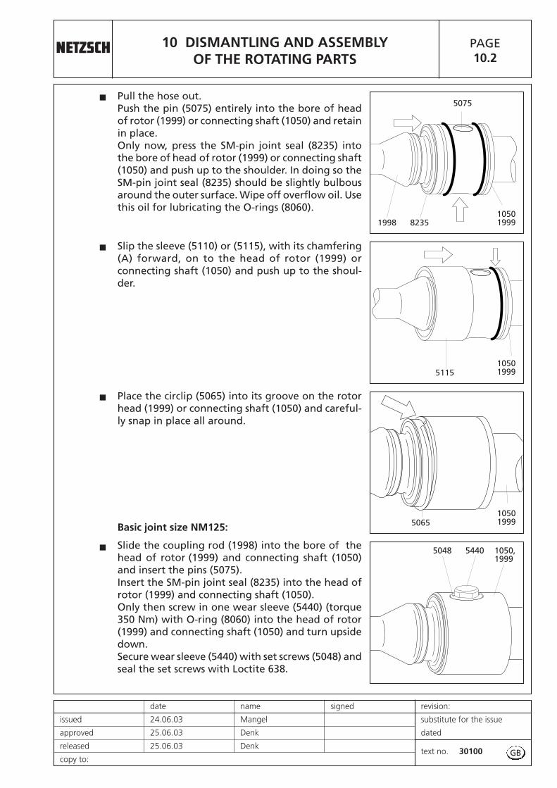
10 DISMANTLING AND ASSEMBLYOF THE ROTATING PARTS
PAGE10.2
date name signed revision:
issued 24.06.03 Mangel substitute for the issue
approved 25.06.03 Denk dated
released 25.06.03 Denktext no. 30100
copy to:
Slip the sleeve (5110) or (5115), with its chamfering(A) forward, on to the head of rotor (1999) orconnecting shaft (1050) and push up to the shoul-der.
Pull the hose out.Push the pin (5075) entirely into the bore of headof rotor (1999) or connecting shaft (1050) and retainin place.Only now, press the SM-pin joint seal (8235) intothe bore of head of rotor (1999) or connecting shaft(1050) and push up to the shoulder. In doing so theSM-pin joint seal (8235) should be slightly bulbousaround the outer surface. Wipe off overflow oil. Usethis oil for lubricating the O-rings (8060).
Place the circlip (5065) into its groove on the rotorhead (1999) or connecting shaft (1050) and careful-ly snap in place all around.
5075
1998 8235
5115
5065
�
�
�
10501999
10501999
10501999
GB
Basic joint size NM125:
Slide the coupling rod (1998) into the bore of thehead of rotor (1999) and connecting shaft (1050)and insert the pins (5075). Insert the SM-pin joint seal (8235) into the head ofrotor (1999) and connecting shaft (1050). Only then screw in one wear sleeve (5440) (torque350 Nm) with O-ring (8060) into the head of rotor(1999) and connecting shaft (1050) and turn upsidedown. Secure wear sleeve (5440) with set screws (5048) andseal the set screws with Loctite 638.
� 5440 1050, 1999
5048

Continued Page 10.3
10 DISMANTLING AND ASSEMBLYOF THE ROTATING PARTS
PAGE10.2R
revision: date name signed
substitute for the issue issued 19.12.05 Mangel
dated approved 20.12.05 Denk
text no. 30100released 20.12.05 Denk
copy to: GB
For lubrication, use an oil can which should befitted with a thin plastic hose having an outside dia-meter of not more than 4 mm.Insert this hose into the upper oil port opening inthe rotor (1999) or connecting shaft (1050). Thenslide the hose end past the coupling rod (1998)all the way down to the bottom section of the rotorhead (1999) or connecting shaft (1050).Slowly fill with lubricating oil up to the filling port.
Pull the hose out.Then insert the hose end through the small gap onthe topside of SM-pin joint seal (8235) and guide itdown to the bottom of the hollow space betweencoupling rod (1998) and SM-pin joint seal (8235).Slowly fill with lubricating oil up to the gap.
Screw in the second wear sleeve (5440) (torque 350Nm) with O-ring (8060) into the head of rotor (1999)and connecting shaft (1050). Secure wear sleeve(5440) with set screws (5048) and seal the set scr-ews with Loctite 638.
�
�
�
1998 5440
10501999
Basic joint size NM021 - NM125:
Drive connecting shaft (1050), coupling rod (1998)and rotor (1999) are now joined by means of the twopin joints.Pump housing (2010), stator (3005) and end stud(2005) may now be fitted.
� 1999 10500085 A1998
1998 8235
5440 5048
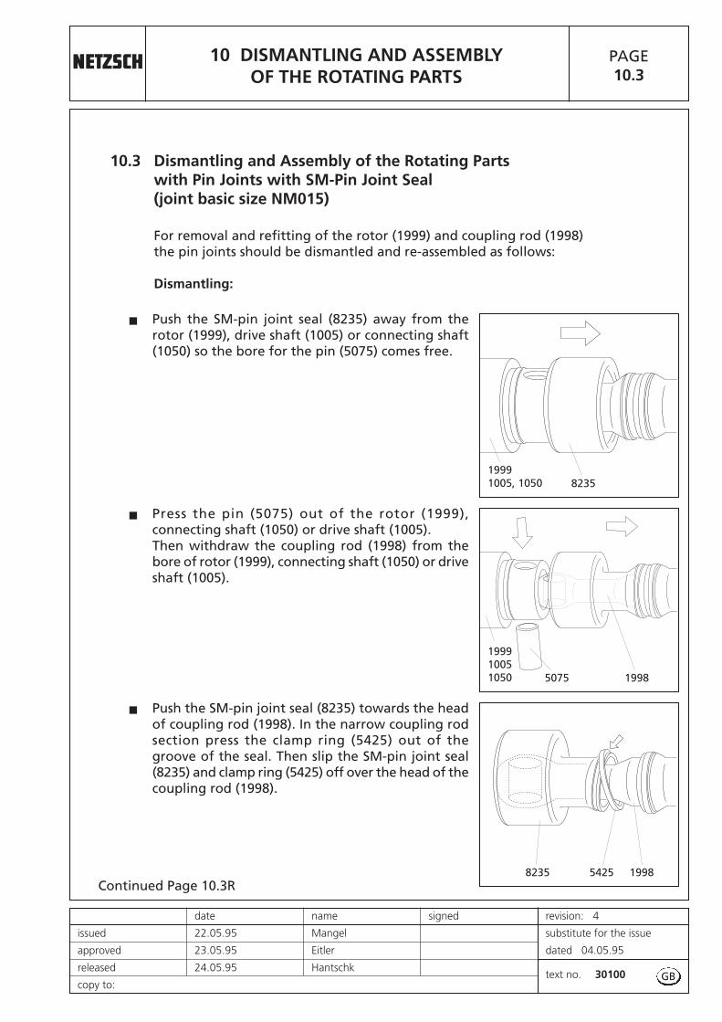
Continued Page 10.3R
10 DISMANTLING AND ASSEMBLYOF THE ROTATING PARTS
PAGE10.3
date name signed revision: 4
issued 22.05.95 Mangel substitute for the issue
approved 23.05.95 Eitler dated 04.05.95
released 24.05.95 Hantschktext no. 30100
copy to:
10.3 Dismantling and Assembly of the Rotating Partswith Pin Joints with SM-Pin Joint Seal(joint basic size NM015)
For removal and refitting of the rotor (1999) and coupling rod (1998)the pin joints should be dismantled and re-assembled as follows:
Dismantling:
Push the SM-pin joint seal (8235) away from therotor (1999), drive shaft (1005) or connecting shaft(1050) so the bore for the pin (5075) comes free.
Press the pin (5075) out of the rotor (1999),connecting shaft (1050) or drive shaft (1005). Then withdraw the coupling rod (1998) from thebore of rotor (1999), connecting shaft (1050) or driveshaft (1005).
Push the SM-pin joint seal (8235) towards the headof coupling rod (1998). In the narrow coupling rodsection press the clamp ring (5425) out of thegroove of the seal. Then slip the SM-pin joint seal(8235) and clamp ring (5425) off over the head of thecoupling rod (1998).
�
�
�
5075
8235
19991005, 1050
199910051050
8235
1998
19985425
GB
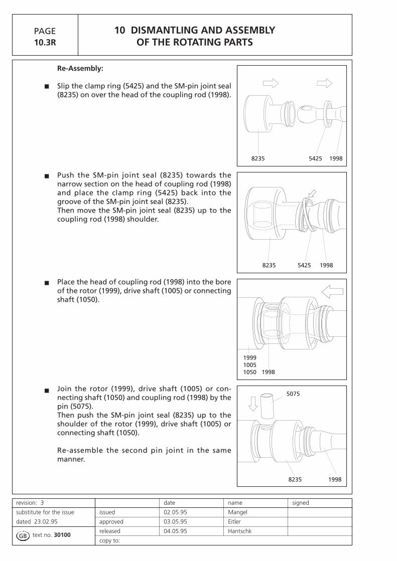
10 DISMANTLING AND ASSEMBLYOF THE ROTATING PARTS
PAGE10.3R
revision: 3 date name signed
substitute for the issue issued 02.05.95 Mangel
dated 23.02.95 approved 03.05.95 Eitler
text no. 30100released 04.05.95 Hantschk
copy to:
Re-Assembly:
Slip the clamp ring (5425) and the SM-pin joint seal(8235) on over the head of the coupling rod (1998).
Push the SM-pin joint seal (8235) towards thenarrow section on the head of coupling rod (1998)and place the clamp ring (5425) back into thegroove of the SM-pin joint seal (8235).Then move the SM-pin joint seal (8235) up to thecoupling rod (1998) shoulder.
Place the head of coupling rod (1998) into the boreof the rotor (1999), drive shaft (1005) or connectingshaft (1050).
Join the rotor (1999), drive shaft (1005) or con-necting shaft (1050) and coupling rod (1998) by thepin (5075).Then push the SM-pin joint seal (8235) up to theshoulder of the rotor (1999), drive shaft (1005) orconnecting shaft (1050).
Re-assemble the second pin joint in the samemanner.
�
�
�
� 5075
8235 1998
8235 19985425
199910051050 1998
8235 19985425
GB

Continued Page 10.4R
�
�
10 DISMANTLING AND ASSEMBLYOF THE ROTATING PARTS
PAGE10.4
date name signed revision: 2
issued 22.03.95 Mangel substitute for the issue
approved 23.03.95 Eitler dated 30.12.94
released 24.03.95 Hantschktext no. 30100
copy to:
10.4 Dismantling and Assembly of the Journal Cross Joints (joint basic size NM125)
Remove the cylindrical head screws (5095 and 5101),then separate the coupling rod (1998) and connec-ting shaft (1050) from each other.
Every journal cross joint should remain closed andfull of lubricant.
If the outer rubber seal sleeve (8151) is undamaged,the joint can generally be used again. Beforerefitting, change the joint oil as described later on.
If damaged, remove the rubber seal sleeves (8151,8150) and check the condition of the joints. Procedure: see Page 10.5, Section 10.5.
5095 1998
1050
8151
5101
GB

Continued Page 10.5
10 DISMANTLING AND ASSEMBLYOF THE ROTATING PARTS
PAGE10.4R
revision: 3 date name signed
substitute for the issue issued 02.05.95 Mangel
dated 24.03.95 approved 03.05.95 Eitler
text no. 30100released 04.05.95 Hantschk
copy to:
Attention when draining off the oil:The oil inside the journal cross joint may be underpressure.Wear goggles!Remove the drain plug (5172) and lubricator (5450)with gasket (5240) and drain the oil into a vessel.Please dispose of this oil in the proper manner.
Screw in the lubricator (5450) with a new gasket(5240).
Remove the drain plug (5051) with gasket (5245).
Fill with fresh oil from below through the R 1/8" borein the lubricator (5450) until only oil without airbubbles comes out of the screw tap on the drain plug(5172).Now move the joint about a little so air bubbles canrise. If necessary, fill again with oil from below.
When the joint is completely filled with oil, removethe discharge pipe (A) and screw in a drain plug(5172) with new gasket (5240). The built-in checkvalve on the lubricator (5450) avoids oil leakage andflow back.Add some more oil under slight pressure until theseals (8150, 8151) are ball shaped.
Now remove the feeding pipe (B).Close filler R 1/8" opening in the lubricator (5450)with plug (5051) and new gasket (5245).
Replace the O–rings (8060).
With cylindrical head screws (5095 and 5101) mountthe rotor (1999), coupling rod (1998) and connectingshaft (1005) on to the joints.The cylindrical head screws (5095 and 5101) do nothave the same length; they should not be mixed up! Use a torque key. The torque should correspond tosectional drawing G… .Secure screws with Loctite*.*For Loctite type see sectional drawing G… .
�
�
�
�
�
�
�
A
B
5172
5240
5051
5245
8060
8060
51011050
50951998
GB
5172
5051, 5245
5240
5240
5450

Continued Page 10.5R
�
�
�
10 DISMANTLING AND ASSEMBLYOF THE ROTATING PARTS
PAGE10.5
date name signed revision: 2
issued 05.02.96 Mangel substitute for the issue
approved 06.02.96 Denk dated 05.04.95
released 07.02.96 Hantschktext no. 30100
copy to:
Netzsch
An
Mohnopumpen GmbH
10.5 Removal and Fitting of the Rubber Seal Sleeves
Slide out the joint shells (5005).Remove the vulcanized metal spacer ring (A) frominner rubber seal sleeve (8150).
For replacement of the rubber seal sleeves (8150,8151) the oil should be drained off first.Procedure: See Page 10.4R, Section 10.4.Remove cylindrical head screws (5195) and pull offclamp rings (5180).Worn or damaged rubber seal sleeves (8150, 8151)can be cut up for better removal.
Check the condition of the joints.The complete joint should be replaced when it isworn or damaged, when there is stiffness in move-ment and excessive slack or a corroded inner partbecause of ruined rubber sleeves (8150, 8151).
Please send a worn or damaged joint to our addressfor repair as special tools are necessary for replacingor repairing the joint items.
5195
5005
A
5005
8151
5180�
GB
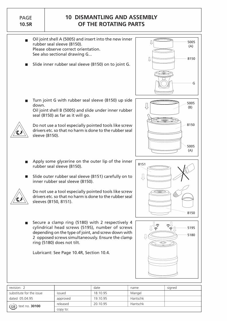
10 DISMANTLING AND ASSEMBLYOF THE ROTATING PARTS
PAGE10.5R
revision: 2 date name signed
substitute for the issue issued 18.10.95 Mangel
dated 05.04.95 approved 19.10.95 Hantschk
text no. 30100 released 20.10.95 Hantschk
copy to:
Oil joint shell A (5005) and insert into the new innerrubber seal sleeve (8150).Please observe correct orientation. See also sectional drawing G...
Slide inner rubber seal sleeve (8150) on to joint G.
Turn joint G with rubber seal sleeve (8150) up sidedown.Oil joint shell B (5005) and slide under inner rubberseal (8150) as far as it will go.
Do not use a tool especially pointed tools like screwdrivers etc. so that no harm is done to the rubber sealsleeve (8150).
Apply some glycerine on the outer lip of the innerrubber seal sleeve (8150).
Slide outer rubber seal sleeve (8151) carefully on toinner rubber seal sleeve (8150).
Do not use a tool especially pointed tools like screwdrivers etc. so that no harm is done to the rubber sealsleeves (8150, 8151).
Secure a clamp ring (5180) with 2 respectively 4cylindrical head screws (5195), number of screwsdepending on the type of joint, and screw down with2 opposed screws simultaneously. Ensure the clampring (5180) does not tilt.
Lubricant: See Page 10.4R, Section 10.4.
�
�
�
�
�
�
8150
G
5005(A)
5005(B)
5005(A)
8150
8151
8150
5180
5195
GB

10 DISMANTLING AND ASSEMBLYOF THE ROTATING PARTS
PAGE10.6
date name signed revision: 1
issued 19.12.05 Mangel substitute for the issue
approved 20.12.05 Denk dated 25.06.03
released 20.12.05 Denktext no. 30100
copy to:
10.6 Replacing the Wear Sleeves of Adapter, Rotor and Coupling Rod(Basic joint size NM045 - NM125)
Basic joint size NM045-NM105:The wear sleeves (5435, 5440) have a very tight fit.A press should be used to remove or refit them.It may be possible though to drive the damagedsleeves out with a suitable mandrel. A rigid vicehowever is needed at the least for pressing newsleeves (5435, 5440) in again.
Orient the wear sleeves (5435) so that their ovalbore agrees with the longitudinal axis of thecoupling rod (1998).
Basic joint size NM125:Orient the centering bores at the sides of wear slee-ves (5435) so that they are visible through the boresof the head of the coupling rod after their inserti-on. No tool is necessary inserting the wear sleeves. Fix the wear sleeves (5435) with set screws (5049) inthe correct position and secure them with Loctite.
Generously oil the wear sleeves (5435, 5440).
Basic joint size NM045-NM105:Every wear sleeve (5435, 5440) has got one smallerouter diameter on one end for better insertion intothe bores of the coupling rod.Ensure the sleeves are placed in the correct orien-tation to the coupling rod (1998).
1998
5435 5440
�
�
GB
1998
5435


11 DISMANTLING AND ASSEMBLY OF THE CONNECTING SHAFT
PAGE11.0
date name signed revision:
issued 24.06.03 Mangel substitute for the issue
approved 25.06.03 Denk dated
released 25.06.03 Denktext no. 30100
copy to:
11 Removal and Fitting of the Connecting Shaftwith Shaft Seal
Removal:
� Push the circlip (1035) in the direction to the mechanical seal.
� Remove pin (1030).
� Remove the shaft seal housing (7005) and mechanical seal (7010) together with connecting shaft (1050) and set ring (1035) from drive stool (0085) and the drive shaft. The thread of cylindrical head screw (1040) can be used as forcing screw.
� If a mechanical seal is installed, see description"Removal and Fitting of Mechanical Seal" after Page 12.0.
Fitting:
� Apply grease into the bore of the connecting shaft (1050) to avoid rust (e.g. TCE-Metallic 600).
� Assemble the shaft seal housing (7005) and mechanical seal (7010) together with connecting shaft (1050) and set ring (1035) with drive stool (0085) and push connecting shaft (1050) on to the drive shaft. At this please observe the installation direction of set ring (1035) (please see mark).
� If a mechanical seal is installed, see description"Removal and Fitting of Mechanical Seal" after Page 12.0.
� Connect the connecting shaft (1050) and the drive shaft by pin (1030). Push set ring (1035) on pin (1030).
GB


12 DISMANTLING AND ASSEMBLY OF THE SHAFT SEALING
PAGE12.0
date name signed revision:
issued 24.06.03 Mangel substitute for the issue
approved 25.06.03 Denk dated
released 25.06.03 Denktext no. 30100
copy to:
12.1 Removal and Fitting of the Single Mechanical Seal
� Carefully slide out mechanical seal housing (7005) together with the parts of the mechanical seal contained in it from connecting shaft (1050).
� Carefully push mechanical seal (7010) stationary seat out of mechanical seal housing (7005).
Refitting is a simple reversal of the above procedure.
� To reduce frictional forces during seal assembly, apply some glycerine to the shaft and the seal housing in the area of the gaskets.
� Special care must be taken when fitting double PTFE-coated gaskets:the joint of the outer coating must point away from the seal assemblydirection, otherwise the coating may open or be pulled off!
Ensure that the distribution of pressure is uniform when insertingthe pressure sensitive counter rings. When inserting larger rings, use a suitable mandrel. Do not allow any foreign bodies to get between the sliding surfaces.
� Exactly keep to the seal installation dimensions and ensure that the sealing faces are correctly pressed together (see table on sectional drawing W ... ).
� Insert mechanical seal (7010) stationary seat into mechanical seal housing (7005).
� Insert mechanical seal housing (7005) together with the stationary seatinto the drive stool without the installed connecting shaft (1050).
� If necessary take the installation dimension from the table and add the thickness S of the set ring (7086) when existing.
� Mark this installation dimension on the connecting shaft (1050).
� Fix the rotating unit of the mechanical seal (7010) on the connceting shaft (1050) depending on the installation dimension so that the rotating unit of the mechanical seal (7010) or the set ring (7086) is at the mark.
� Insert connecting shaft (1050) with the rotating unit of the mechanical seal (7010) into drive stool (0085) and install lip seal (7091, if existing. Push the set ring (1035) on to connecting shaft (1050) and observe at this the installation direction (see mark). Push connecting shaft (1050) on to the drive shaft and connect with pin (1030). Push the set ring (1035) on pin (1030).
GB


13 DISMANTLING AND ASSEMBLYOF SPECIAL UNITS
PAGE13.0
date name signed revision:
issued 24.06.03 Mangel substitute for the issue
approved 25.06.03 Denk dated
released 25.06.03 Denktext no. 30100
copy to:
Inspection Opening at the Pump Housing
gray cast iron model on from size NM045
design for welded housings – nominal size DN 76,1 – ISO 2852
2018
2070
2650
GG...
2045 2055 20608050
GB


13 DISMANTLING AND ASSEMBLYOF SPECIAL UNITS
PAGE13.1
date name signed revision:
issued 24.06.03 Mangel substitute for the issue
approved 25.06.03 Denk dated
released 25.06.03 Denktext no. 30100
copy to:
Stator heating jacket
Stator protecting tube
8030 80303085
8030 80303025
GB
Additional accessories, if fitted, pls. see after section 15.


14 RECOMMENDED STOCK OF WEAR PARTS
PAGE14.0
date name signed revision:
issued 24.06.03 Mangel substitute for the issue
approved 25.06.03 Denk dated
released 25.06.03 Denktext no. 30100
copy to:
14 Recommended Spare Parts
In general, we have all spare parts in stock. Our subsidiaries and exclusiverepresentatives also hold a certain stock. For special cases and when shortwaiting periods are not acceptable, we recommend to keep an amount of spare parts, corresponding to the pump, in stock on site (please see table below).
– Rotor – Stator – Elastomer parts as O-rings and sleeves – joint parts – shaft seals.
To avoid mistakes in delivery, please identify the parts by their position number shown in the spare parts list or on the sectional drawing.
For placing a spare parts order, it is absolutely necessary to give the following details:
Pieces - Designation - Identification Number(see column 2) (see column 3) (see column 4)
The column details are taken from the spare parts list. See example.
GB
Example:
1 2 3 4
PART Designation Ident-NumberEURO POS. Quantity Unit Size – Norm – Material/Surface
3410 0005 1,000 pc bearing housing 850221
2910 0010 1,000 pc distance sleeve 850220
3520 0015 1,000 pc bearing cover 850222
SPARE PARTS LIST 10.05.94 10:50:18 Page: 1 / 5

15 SECTIONAL DRAWINGS AND LIST OF SPARE PARTS
PAGE15.0
date name signed revision:
issued 24.06.03 Mangel substitute for the issue
approved 25.06.03 Denk dated
released 25.06.03 Denktext no. 30100
copy to:
15 Sectional Drawings and List of Spare Parts
GB


NM06
3-
NM12
5mi
tLo
ctite
245
gesich
ert
secu
red
with
Loct
ite24
5
NM105B
Y02S
12-
-NM
125B
Y02S
12-
NM105B
Y01L
06-
-NM
125B
Y01L06
-NM
053B
Y01P
05-
-NM
090B
Y01P
05-
NM05
3BY0
2D09
--
NM12
5BY0
2D09
-NM
015B
Y04S
24-
-NM
038B
Y04S
24-
NM04
5BY-
-S18
--
NM10
5BY-
-S18-
Maßs
t./Sc
ale:
Type
:
Datu
m/
date
Name
/na
meUn
ters
chrif
t/Sign
atur
ege
zeich
net/
draw
nge
prüf
t/
chec
ked
freige
gebe
n/
releas
ed
Dist
ribut
or:
Revision
:
Ersa
tzfü
rAu
sgab
evo
m:Re
plac
emen
tfo
rVe
rsion
of:
Zeich
nung
-Nr.:
Draw
ing
No.:
Verteiler:
06.07.20
04Th
oma
NMBY
010.00
0
1:X
1
03.06.20
042
/3
/49
/50
/51
/52
/56
/58
/98
/Ex
p.
06.07.20
04De
nk06
.07.20
04De
nk
1999
5075
8060
5115
5065
8235
5425
1998
5425
8235
5065
5115
8060
1040
1045
5075
1050
1030
7010
0140
0120
0125
9500
0085
2030
2025
1035
7005
8015
2020
2010
3070
2035
3020
2016
8012
203530
70
3020
3010
2015
8010
3015
3020
3005
NM01
5BY0
2S12
--
NM12
5BY0
2S12
-NM
015B
Y01L
06-
-NM
125B
Y01L
06-
NM01
5BY0
1P05
--
NM09
0BY0
1P05
-NM
053B
Y02D
09-
-NM
125B
Y02D
09-
NM01
5BY0
4S24
--
NM03
8BY0
4S24
-NM
045B
Y--S
18-
-NM
105B
Y--S
18-
0560
(Opt
ion)
2005
Th
e h
ea
rt o
f y
ou
r p
roc
es
s

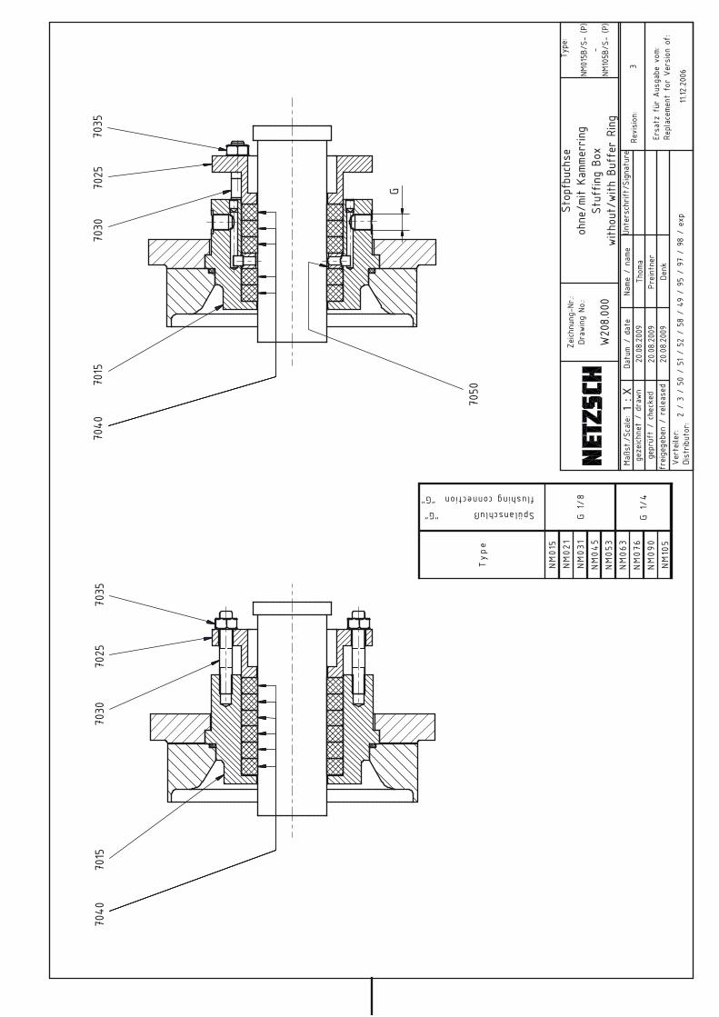
Type
Spülanschluß "G"
flushing connection "G"
NM01
5NM02
1NM03
1NM04
5NM05
3NM06
3NM07
6NM09
0NM10
5
G1/
8
G1/
4
Maßs
t./Sc
ale:
Type
:
Datu
m/
date
Name
/na
meUn
ters
chrif
t/Sign
atur
ege
zeich
net
/dr
awn
gepr
üft
/ch
ecke
dfr
eige
gebe
n/
releas
ed
Dist
ribut
or:
Revision
:
Ersa
tzfü
rAu
sgab
evo
m:Re
plac
emen
tfo
rVe
rsion
of:
Zeich
nung
-Nr.:
Draw
ing
No.:
Vert
eiler:
20.08.20
09Th
oma
W20
8.00
0
1:X
NM01
5B/S
-(P
)-
NM10
5B/S
-(P
)
3
11.12
.200
6
Stop
fbuc
hse
ohne
/mit
Kamm
errin
gSt
uffin
gBo
xwith
out/
with
Buffer
Ring
2/
3/
50/
51/
52/
58/
49/
95/
97/
98/
exp
20.08.20
09Pr
eint
ner
20.08.20
09De
nk
7015
7030
7025
7035
7015
7030
7025
7035
7050
G
7040
7040


üünn
NM01
50
--
NM02
10
--
NM03
112
,5-
--
B17
,5K
-B
22,5
K-
B25
,5K
NM06
327
,5-
-NM
076
20-
-NM
090
30-
-NM
105
25-
-
""
NM03
8
NM04
5
NM05
3
10 15 22,5nn
ee
Maßs
t./Sc
ale:
Type
:
Datu
m/
date
Name
/na
meUn
ters
chrif
t/Sign
atur
ege
zeich
net
/dr
awn
gepr
üft
/ch
ecke
dfr
eige
gebe
n/
releas
ed
Dist
ribut
or:
Revision
:
Ersa
tzfü
rAu
sgab
evo
m:Re
plac
emen
tfo
rVe
rsion
of:
Zeich
nung
-Nr.:
Draw
ing
No.:
Vert
eiler:
20.08.20
09Th
oma
W20
9.00
0
1:X
NM01
5B/S
-(P
)-
NM10
5B/S
-(P
)
4
11.12
.200
6
Einf
.wirk
.GLR
DSing
leMe
chan
icalSe
al
2/
3/
50/
51/
52/
58/
49/
95/
97/
98/
exp
20.08.20
09Pr
eint
ner
20.08.20
09De
nk
MG1/G6
0KU
/DIN2
4960
NU/
DIN2
4960
MG1/G6
0
Ausf
ühru
ngK
(K-G
elen
k)
vers
ion
K(gea
r-joint)
NM03
1B/S
-(P)
-NM
105B
/S-
(P)
mit
Loct
ite63
8eing
edich
tet
sealed
with
Loctite
638
mit
Loct
ite63
8eing
edich
tet
sealed
with
Loct
ite63
8
Ausf
ühru
ngB
(Bolze
ngelen
k)
vers
ion
B(pin-joint
)
7010
7005
7086
7010
7005
7010
7005
7126
X
mit
Loct
ite24
5ge
sich
ert
secu
red
with
Loct
ite24
5
7126
X170
86
mit
Loct
ite24
5ge
sich
ert
secu
red
with
Loctite
245
7005
7010


NM015
10,5
0NM021
10,5
0NM031
20,
512
,5NM03
817
,510
NM04
522,
515
NM05
325,
522
,5NM06
330,
527
,5NM07
630
20NM09
036,
530
NM10
530,
525
G1/
4
ttnngg
G1/
8
TTppee
SSppüüuu
gg oonntt
Maßs
t./Sc
ale:
Type
:
Datu
m/
date
Name
/na
meUn
ters
chrif
t/Sign
atur
ege
zeich
net
/dr
awn
gepr
üft
/ch
ecke
dfr
eige
gebe
n/
releas
ed
Dist
ribut
or:
Revision
:
Ersa
tzfü
rAu
sgab
evo
m:Re
plac
emen
tfo
rVe
rsion
of:
Zeich
nung
-Nr.:
Draw
ing
No.:
Vert
eiler:
20.08.20
09Th
oma
W210.00
0
1:X
NM01
5B/S
-(P
)-
NM10
5B/S
-(P
)
4
11.12
.200
6
Einf
.wirk
.GLR
Dmi
tQu
ench
ansc
hluß
Sing
leMe
chan
icalSe
alwith
Quen
ch
2/
3/
50/
51/
52/
58/
49/
95/
97/
98/
exp
20.08.20
09Pr
eint
ner
20.08.20
09De
nk
7010
7086
7010
7010
7126
MG1/
G60
KU/
DIN2
4960
NU/
DIN2
4960
X
7086
7126
mit
Loct
ite63
8eing
edich
tet
sealed
with
Loctite
638
mit
Loct
ite63
8eing
edich
tet
sealed
with
Loct
ite63
8
mit
Loct
ite63
8eing
edich
tet
sealed
with
Loctite
638
X
G
7005
7005
7005
NM03
1B/S
-(P)
-NM
105B
/S-
(P)
mit
Loct
ite24
5ge
sich
ert
secu
red
with
Loct
ite24
5mi
tLo
ctite
245
gesich
ert
secu
red
with
Loct
ite24
5
7126
7091
7091
7091


Maßs
t./Sc
ale:
Type
:
Datu
m/
date
Name
/na
meUn
ters
chrif
t/Sign
atur
ege
zeich
net
/dr
awn
gepr
üft
/ch
ecke
dfr
eige
gebe
n/
releas
ed
Dist
ribut
or:
Revision
:
Ersa
tzfü
rAu
sgab
evo
m:Re
plac
emen
tfo
rVe
rsion
of:
Zeich
nung
-Nr.:
Draw
ing
No.:
Vert
eiler:
29.06.20
04Pr
eint
ner
W219.00
0
1:X
NM12
5B-(P)
Stop
fbuc
hse
ohne
/mit
Kamm
errin
gSt
uffin
gBo
xwith
out/
with
Buffer
Ring
2/
3/
50/
51/
52/
58/
exp
29.06.20
04De
nk29
.06.20
04De
nk
G1/4
7035
7025
7030
7015
7040
7015
7030
7025
7035
7050
7040
Th
e h
ea
rt o
f y
ou
r p
roc
es
s

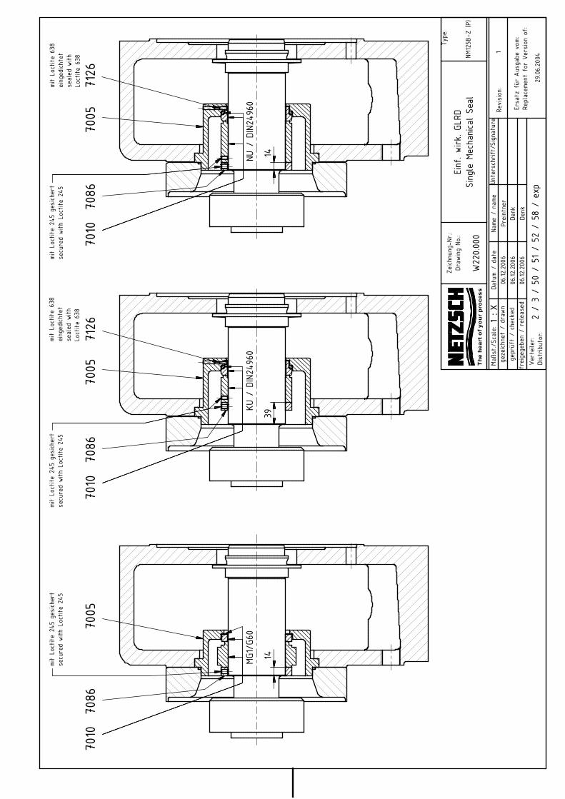
Maßs
t./Sc
ale:
Type
:
Datu
m/
date
Name
/na
meUn
ters
chrif
t/Sign
atur
ege
zeich
net
/dr
awn
gepr
üft
/ch
ecke
dfr
eige
gebe
n/
releas
ed
Dist
ribut
or:
Revision
:
Ersa
tzfü
rAu
sgab
evo
m:Re
plac
emen
tfo
rVe
rsion
of:
Zeich
nung
-Nr.:
Draw
ing
No.:
Vert
eiler:
06.12
.200
6Pr
eint
ner
W22
0.00
0
1:X
NM125B
-Z(P
)
1
29.06.20
04
Einf
.wirk
.GLR
DSing
leMe
chan
icalSe
al
2/
3/
50/
51/
52/
58/
exp
06.12
.200
6De
nk06
.12.200
6De
nk
MG1/G6
0KU
/DIN2
4960
NU/
DIN2
4960
mitLo
ctite
638
eing
edich
tet
sealed
with
Loct
ite63
8
mit
Loct
ite63
8eing
edich
tet
sealed
with
Loct
ite63
8
7126
7005
7086
7010
7086
7005
7126
7010
7005
7086
7010
1439
14
mit
Loctite
245
gesich
ert
secu
red
with
Loctite
245
mit
Loct
ite24
5ge
sich
ert
secu
red
with
Loctite
245
mit
Loctite
245
gesich
ert
secu
red
with
Loct
ite24
5
Th
e h
ea
rt o
f y
ou
r p
roc
es
s


(1:5
)
Maßs
t./Sc
ale:
Type
:
Datu
m/
date
Name
/na
meUn
ters
chrif
t/Sign
atur
ege
zeich
net
/dr
awn
gepr
üft
/ch
ecke
dfr
eige
gebe
n/
releas
ed
Dist
ribut
or:
Revision
:
Ersa
tzfü
rAu
sgab
evo
m:Re
plac
emen
tfo
rVe
rsion
of:
Zeich
nung
-Nr.:
Draw
ing
No.:
Vert
eiler:
06.12
.200
6Pr
eint
ner
W22
1.000
1:X
NM125B
-Z(P
)
1
29.06.20
04
Einf
.wirk
.GLR
DmitQu
ench
ansc
hluß
Sing
leMe
chan
icalSe
alwith
Quen
ch
2/
3/
50/
51/
52/
58/
exp
06.12
.200
6De
nk06
.12.200
6De
nk
7010
7005
7126
7091
7086
7010
7086
7005
7126
7091
mitLo
ctite
638
eing
edich
tet
sealed
with
Loct
ite63
8
mitLo
ctite
638
eing
edich
tet
sealed
with
Loct
ite63
8
7010
7086
7005
7126
7091
mit
Loct
ite63
8eing
edich
tet
sealed
with
Loct
ite63
8
MG1/G6
0KU
/DIN2
4960
NU/
DIN2
4960
G1/4
mit
Loct
ite24
5ge
sich
ert
secu
red
with
Loct
ite24
5
44,5
39
mit
Loct
ite24
5ge
sich
ert
secu
red
with
Loct
ite24
5
14
mit
Loct
ite24
5ge
sich
ert
secu
red
with
Loct
ite24
5
Th
e h
ea
rt o
f y
ou
r p
roc
es
s


Maßs
t./Sc
ale:
Type
:
Datu
m/
date
Name
/na
meUn
ters
chrif
t/Sign
atur
ege
zeich
net
/dr
awn
gepr
üft
/ch
ecke
dfr
eige
gebe
n/
releas
ed
Dist
ribut
or:
Revision
:
Ersa
tzfü
rAu
sgab
evo
m:Re
plac
emen
tfo
rVe
rsion
of:
Zeich
nung
-Nr.:
Draw
ing
No.:
Vert
eiler:
06.12
.200
6Pr
eint
ner
W23
8.00
0
1:X
NM125B
-B(P
)
1
08.03.20
06
Einf
.wirk
.GLR
DSing
leMe
chan
icalSe
al
2/
3/
50/
51/
52/
58/
95/
exp
06.12
.200
6De
nk06
.12.200
6De
nk
MG1/G6
0KU
/DIN2
4960
NU/
DIN2
4960
7010
7005
7086
7010
7005
7126
mit
Loct
ite63
8eing
edich
tet
sealed
with
Loct
ite63
8
7010
7005
7126
mitLo
ctite
638
eing
edich
tet
sealed
with
Loct
ite63
8
25
mit
Loctite
245
gesich
ert
secu
red
with
Loct
ite24
5mit
Loct
ite24
5ge
sich
ert
secu
red
with
Loct
ite24
5
Th
e h
ea
rt o
f y
ou
r p
roc
es
s


Maßs
t./Sc
ale:
Type
:
Datu
m/
date
Name
/na
meUn
ters
chrif
t/Sign
atur
ege
zeich
net
/dr
awn
gepr
üft
/ch
ecke
dfr
eige
gebe
n/
releas
ed
Dist
ribut
or:
Revision
:
Ersa
tzfü
rAu
sgab
evo
m:Re
plac
emen
tfo
rVe
rsion
of:
Zeich
nung
-Nr.:
Draw
ing
No.:
Vert
eiler:
06.12
.200
6Pr
eint
ner
W23
9.00
0
1:X
NM125B
-B(P
)
1
08.03.20
06
Einf
.wirk
.GLR
DmitQu
ench
ansc
hluß
Sing
leMe
chan
icalSe
alwith
Quen
ch
2/
3/
50/
51/
52/
58/
95
06.12
.200
6De
nk06
.12.200
6De
nk
MG1/G6
0KU
/DIN2
4960
NU/
DIN2
4960
7010
7086
7086
7010
mit
Loct
ite63
8eing
edich
tet
sealed
with
Loct
ite63
8
7010
mit
Loct
ite63
8eing
edich
tet
sealed
with
Loct
ite63
8
7005
7126
7091
mit
Loct
ite63
8eing
edich
tet
sealed
with
Loctite
638
7005
7126
7091
7005
7126
7091
G1/4
30,5
mit
Loct
ite24
5ge
sich
ert
secu
red
with
Loct
ite24
5
25
mit
Loct
ite24
5ge
sich
ert
secu
red
with
Loct
ite24
5mit
Loct
ite24
5ge
sich
ert
secu
red
with
Loct
ite24
5
Th
e h
ea
rt o
f y
ou
r p
roc
es
s


B-B
B
B
Maßst./Scale:
Type:
Datum / date Name / name Unterschrift/Signaturegezeichnet / drawngeprüft / checked
freigegeben / released
Distributor:
Revision:
Ersatz für Ausgabe vom: Replacement for Version of:
Zeichnung-Nr.:Drawing No.:
Verteiler:
06.10.2009 Thoma
W251.000
1 : X
NM015B/S (P)-
NM105B/S (P).
NM125B
2
06.11.2007
Laufwerkdichtung mit Schmieranschluß undWDR-Ausrücksicherung
Single Mech. Seal with Lubrication connection and lipseal-securing
2 / 3 / 50 / 51 / 52 / 58
06.10.2009 Denk06.10.2009 Denk
7157
7162
7165
7005 7091 7011 70757010
mit Loctite 245 gesichertsecured with Loctite 245
7130
7135
Ausführung Z-Gelenkversion Z-joint

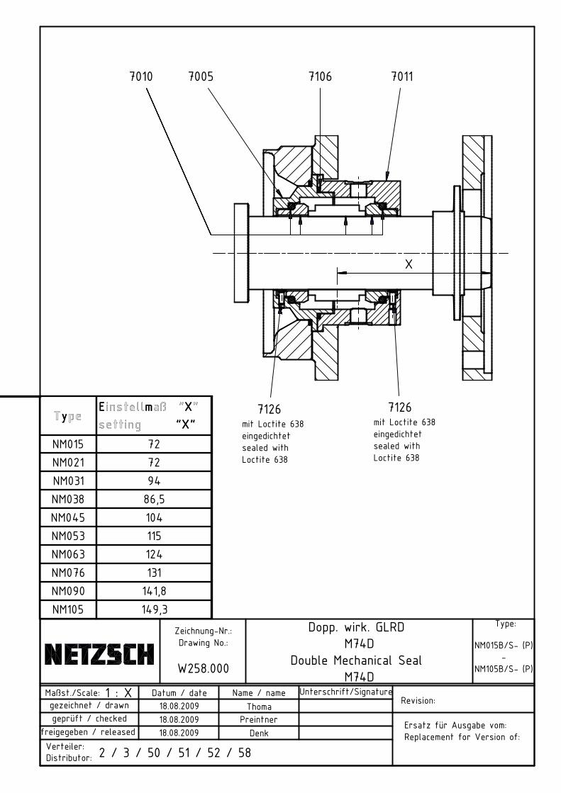
yyEE mm XX
""XX""NM015 72NM021 72NM031 94NM038 86,5NM045 104NM053 115NM063 124NM076 131NM090 141,8NM105 149,3
Maßst./Scale:
Type:
Datum / date Name / name Unterschrift/Signaturegezeichnet / drawngeprüft / checked
freigegeben / released
Distributor:
Revision:
Ersatz für Ausgabe vom: Replacement for Version of:
Zeichnung-Nr.:Drawing No.:
Verteiler:
18.08.2009 Thoma
W258.000
1 : X
NM015B/S- (P)-
NM105B/S- (P)
Dopp. wirk. GLRD M74D
Double Mechanical Seal M74D
2 / 3 / 50 / 51 / 52 / 58
18.08.2009 Preintner18.08.2009 Denk
mit Loctite 638 eingedichtetsealed with Loctite 638
mit Loctite 638eingedichtetsealed with Loctite 638
7010 7005 70117106
7126 7126
X


SSppüü
ccuu
iinn
cc ttnn
NM01
50
10,5
NM02
10
10,5
NM03
112
,520
,5NM
038
1017
,5NM
045
1522
,5NM
053
22,5
25,5
NM06
327
,530
,5NM
076
2030
,2NM
090
3036
,5NM
105
2530
,5
ss ss
G1/
8
G1/
4Ma
ßst./
Scale:
Type
:
Datu
m/
date
Name
/na
meUn
ters
chrif
t/Sign
atur
ege
zeich
net
/dr
awn
gepr
üft
/ch
ecke
dfr
eige
gebe
n/
releas
ed
Dist
ribut
or:
Revision
:
Ersa
tzfü
rAu
sgab
evo
m:Re
plac
emen
tfo
rVe
rsion
of:
Zeich
nung
-Nr.:
Draw
ing
No.:
Vert
eiler:
16.02.20
10Th
oma
W26
2.00
0
1:X
NM01
5B/S
-(P
)-
NM10
5B/S
-(P
)
Einf
.wirk
.GLR
Dmit
Spülan
schluß
Sing
leMe
chan
icalSe
alwith
flus
hing
conn
ectio
n
2/
3/
49/
50/
51/
52/
58
16.02.20
10Pr
eint
ner
16.02.20
10De
nk
KU/
DIN2
4960
NU/
DIN2
4960
MG1/G6
0
NM03
1B/S
-(P)
-NM
105B
/S-
(P)
mit
Loct
ite63
8eing
edich
tet
sealed
with
Loct
ite63
8
mit
Loct
ite63
8eing
edich
tet
sealed
with
Loct
ite63
8
7086
7010
7010
X
mit
Loct
ite24
5ge
sich
ert
secu
red
with
Loctite
245
7126
X1
7086
mit
Loct
ite24
5ge
sich
ert
secu
red
with
Loct
ite24
5
7005
7010
G
7008
7007
7005
7008
7007
7005
7008
7007
G
G
7126

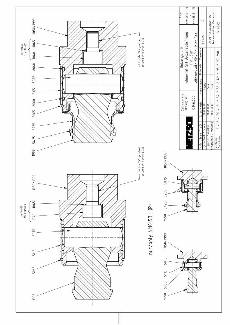
abNM
063
from
NM06
3ab
NM06
3fr
omNM
063
Maßs
t./Sc
ale:
Type
:
Datu
m/
date
Name
/na
meUn
ters
chrif
t/Sign
atur
ege
zeich
net/
draw
nge
prüf
t/
chec
ked
freige
gebe
n/
releas
ed
Dist
ribut
or:
Revision
:
Ersa
tzfü
rAu
sgab
evo
m:Re
plac
emen
tfo
rVe
rsion
of:
Zeich
nung
-Nr.:
Draw
ing
No.:
Verteiler:
01.09.20
09Th
oma
G146
.000
1:X
NM01
5B/S
-(P)
-NM
105B
/S-
(P)
2
14.10
.200
3
Bolzen
gelenk
ohne
/mit
SM-B
olze
nabd
ichtu
ngPin
Joint
with
out/
with
SM-P
inJo
int
Seal
2/
3/
50/
51/
52/
58/
49/
95/
97/9
8
01.09.20
09De
nk01
.09.20
09De
nk
1998
5065
5115
1040
1045
1050
/199
950
751998
5425
8235
5065
8060
5115
5075
8060
1040
1045
1050
/199
9
mitLo
ctite
245
gesich
ert
secu
red
with
Loct
ite24
5mitLo
ctite
245
gesich
ert
secu
red
with
Loct
ite24
5
5065
5115
1050
/199
950
751998
1998
5425
8235
5075
1050
/199
9
nur/
only
NM015B
-(P)


abNM
063
from
NM06
3ab
NM06
3fr
omNM
063
Maßs
t./Sc
ale:
Type
:
Datu
m/
date
Name
/na
meUn
ters
chrif
t/Sign
atur
ege
zeich
net/
draw
nge
prüf
t/
chec
ked
freige
gebe
n/
releas
ed
Dist
ribut
or:
Revision
:
Ersa
tzfü
rAu
sgab
evo
m:Re
plac
emen
tfo
rVe
rsion
of:
Zeich
nung
-Nr.:
Draw
ing
No.:
Verteiler:
02.09.20
09Th
oma
G147
.000
1:X
NM04
5B/S
-(P)
-NM
105B
/S-
(P)
1
23.05.20
03
Bolzen
gelenk
mitVe
rsch
l.-Bu
chse
ohne
/mit
SM-B
olze
nabd
ichtu
ngPin
Joint
with
Wea
rSl
eeve
swith
out/
with
SM-P
inJo
int
Seal
2/
3/
50/
51/
52/
58/
49/
95/
97/
98
02.09.20
09De
nk02
.09.20
09De
nk
1998
5065
5115
1040
1045
1050
/199
950
751998
5425
8235
5065
8060
5115
5075
8060
1040
1045
1050
/199
9
mitLo
ctite
245
gesich
ert
secu
red
with
Loctite
245
mitLo
ctite
245
gesich
ert
secu
red
with
Loct
ite24
554
3554
4054
4054
35


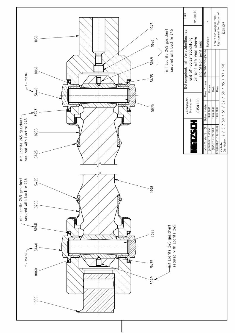
mit
Loctite
245
gesich
ert
secu
red
with
Loctite
245
Maßs
t./Sc
ale:
Type
:
Datu
m/
date
Name
/na
meUn
ters
chrif
t/Sign
atur
ege
zeich
net
/dr
awn
gepr
üft
/ch
ecke
dfr
eige
gebe
n/
releas
ed
Dist
ribut
or:
Revision
:
Ersa
tzfü
rAu
sgab
evo
m:Re
plac
emen
tfo
rVe
rsion
of:
Zeich
nung
-Nr.:
Draw
ing
No.:
Vert
eiler:
13.02.20
09Ro
sam
G158
.000
1:X
NM12
5B-(P)
4
22.05.20
07
Bolzen
gelenk
mitVe
rsch
leißbu
chse
und
SM-B
olze
nabd
ichtu
ngpin
jointwith
wear
slee
vean
dSM
-pin
jointse
al
2/
3/
50/
51/
52/
58/
95/
97/
98
13.02.20
09De
nk13
.02.20
09De
nk
1050
1040
5049
5075
8235
8235
5049
5440
5075
5435
1998
1045
5425
5425
mitLo
ctite
245
gesich
ert
secu
red
with
Loctite
245
1999
mitLo
ctite
245
gesich
ert
secu
red
with
Loctite
245
5048
5435
8060
8060
5440
5048
mitLo
ctite
245
gesich
ert
secu
red
with
Loct
ite24
5T
=35
0Nm
T=
350
Nm


16 ADDRESSES PAGE16.0
issued 19.04.10 Revision 1 text no.16000-1/1copy to:
Consultation Teams:
During our business hours from Monday until Thursday 08:00h bis 17:00h, resp. Friday from08:00h to 15:00h you can reach your personal consultant directly via the standard phonenumbers, fax or e-mail:
NETZSCH Mohnopumpen GmbHGeretsrieder Str. 1D-84478 WaldkraiburgPhone.: +49 8368 63-0Fax: +49 8638 67981E-Mail: [email protected]: www.netzsch.com
Service-Hotline:
Spare parts supply - Consultancy - Servicefor all industries and market sectors off our business hours as well as around the clock onsundays and public holidays:
SERVICE - HOTLINE: +49 8638 63 63 63
Business field Environment & Energy
Phone: +49 8638 63-1010Fax: +49 8638 63-2333E-Mail: [email protected]
Business field Chemicals & Paper
Phone: +49 8638 63-1020Fax: +49 8638 63-2327E-Mail: [email protected]
Business field Food & Pharmaceuticals
Phone: +49 8638 63-1030Fax: +49 8638 63-2358E-Mail: [email protected]
Business field Oil & Gas
Phone: +49 8638 63-1024Fax: +49 8638 63-2333E-Mail: [email protected]
For technical consulting and engineering offices and service centres in almost any Europeancountry and overseas, you can find the latest data:
- for Germany: http://www.netzsch-pumpen.de/de/beratung/
- worldwide: http://www.netzsch-pumpen.de/en/consultation/
- for Italy: http://www.netzsch-pumpen.de/it/assistenza/