INVITED PAPER Massive MIMO, Non-Orthogonal Multiple...
21
Received April 27, 2017, accepted May 25, 2017, date of publication July 11, 2017, date of current version August 14, 2017. Digital Object Identifier 10.1109/ACCESS.2017.2725919 INVITED PAPER Massive MIMO, Non-Orthogonal Multiple Access and Interleave Division Multiple Access CHONGBIN XU 1,2 , YANG HU 3 , CHULONG LIANG 3 , JUNJIE MA 4 , AND LI PING 3 , (Fellow, IEEE) 1 Key Laboratory for Information Science of Electromagnetic Waves (MoE), the Department of Communication Science and Engineering, Fudan University, Shanghai 200433, China 2 National Mobile Communications Research Laboratory, Southeast University, Nanjing 210096, China 3 Department of Electronic Engineering, City University of Hong Kong, Hong Kong 4 Department of Statistics, Columbia University, New York, NY 10027-6902 USA Corresponding author: Yang Hu ([email protected]) This work was supported in part by the National Natural Science Foundation of China under Grant 61501123, in part by the Open Research Fund of the National Mobile Communications Research Laboratory, Southeast University, under Grant 2015D06, in part by the University Grants Committee of the Hong Kong Special Administrative Region, China, under Project AoE/E-02/08, Project CityU 11208114, Project CityU 11217515, and Project CityU 11280216, and in part by the European Union through ICT projects under Project ICT-217033 WHERE and Project ICT-248894 WHERE2. ABSTRACT This paper provides an overview on the rationales in incorporating massive multiple-input multiple-output (MIMO), non-orthogonal multiple access (NOMA), and interleave division multiple access (IDMA) in a unified framework. Our emphasis is on multi-user gain that refers to the advantage of allowing multi-user transmission in massive MIMO. Such a gain can potentially offer tens or even hundreds of times of rate increase. The main difficulty in achieving multi-user gain is the reliance on accurate channel state information (CSI) in the existing schemes. With accurate CSI, both OMA and NOMA can deliver performance not far away from capacity. Without accurate CSI, however, most of the existing schemes do not work well. We outline a solution to this difficulty based on IDMA and iterative data-aided channel estimation (DACE). This scheme can offer very high throughput and is robust against the pilot contamination problem. The receiver cost is low, since only maximum ratio combining (MRC) is involved and there is no matrix inversion or decomposition. Under time division duplex, accurate CSI acquired in the up-link can be used to support low-cost down-link solutions, such as zero forcing. These findings offer useful design considerations for future systems. INDEX TERMS Massive MIMO, NOMA, IDMA, iterative MRC and DACE. I. INTRODUCTION Multiple-input multiple-output (MIMO) is a wireless tech- nology employing multiple transmit and receive anten- nas [1]–[11]. Massive MIMO refers to the situation when the number of antennas involved is very large [12]–[18]. A typical massive MIMO setting is unbalanced, with far more antennas at a base station (BS) than those at a mobile terminal (MT) due to different physical sizes. Massive MIMO provides abundant spatial diversity. How to make best use of such diversity with low cost is a research topic of important practical implications. Channel state information (CSI) plays an important role in massive MIMO. CSI quality can be affected by, e.g., channel estimation error [19], channel vari- ation and RF calibration error [20]. The correlation among different pilots also results in the so-called pilot contamina- tion problem [12], [13], [21], [22]. CSI errors may seriously affect performance in massive MIMO. Conventional orthogonal multiple access (OMA) schemes, such as frequency division multiple access (FDMA) and time division multiple access (TDMA), rely on orthogonality in either frequency or time to avoid interference. In MIMO, orthogonality can also be established in space via zero forcing (ZF) [2]. In the absence of interference, simple single- user detection (SUD) is sufficient in OMA. Non-orthogonal multiple access (NOMA) refers to multi- user transmission schemes that allow interference among users. The concept of NOMA with power control (PC) and successive interference cancelation (SIC) was introduced in [23]. It was shown in [24] that PC-SIC is asymptoti- cally capacity approaching in MIMO up-links when user number is sufficiently large. Recently, NOMA based on PC-SIC has been widely discussed to improve the fairness issue [25]–[32]. In general, MIMO capacity can only be achieved by NOMA but not by OMA [4]–[7]. Multi-user detec- tion (MUD) [2], [24], [33]–[39] is required for this purpose. Therefore NOMA has a theoretical advantage. The differ- ence, though, can be minor under perfect CSI in practical 14728 2169-3536 2017 IEEE. Translations and content mining are permitted for academic research only. Personal use is also permitted, but republication/redistribution requires IEEE permission. See http://www.ieee.org/publications_standards/publications/rights/index.html for more information. VOLUME 5, 2017
Transcript of INVITED PAPER Massive MIMO, Non-Orthogonal Multiple...

Received April 27, 2017, accepted May 25, 2017, date of publication July 11, 2017, date of current version August 14, 2017.
Digital Object Identifier 10.1109/ACCESS.2017.2725919
INVITED PAPER
Massive MIMO, Non-Orthogonal Multiple Accessand Interleave Division Multiple AccessCHONGBIN XU1,2, YANG HU3, CHULONG LIANG3, JUNJIE MA4, AND LI PING3, (Fellow, IEEE)1Key Laboratory for Information Science of Electromagnetic Waves (MoE), the Department of Communication Science and Engineering, Fudan University,Shanghai 200433, China2National Mobile Communications Research Laboratory, Southeast University, Nanjing 210096, China3Department of Electronic Engineering, City University of Hong Kong, Hong Kong4Department of Statistics, Columbia University, New York, NY 10027-6902 USA
Corresponding author: Yang Hu ([email protected])
This work was supported in part by the National Natural Science Foundation of China under Grant 61501123, in part by the Open ResearchFund of the National Mobile Communications Research Laboratory, Southeast University, under Grant 2015D06, in part by the UniversityGrants Committee of the Hong Kong Special Administrative Region, China, under Project AoE/E-02/08, Project CityU 11208114,Project CityU 11217515, and Project CityU 11280216, and in part by the European Union through ICT projects under Project ICT-217033WHERE and Project ICT-248894 WHERE2.
ABSTRACT This paper provides an overview on the rationales in incorporating massive multiple-inputmultiple-output (MIMO), non-orthogonal multiple access (NOMA), and interleave division multipleaccess (IDMA) in a unified framework. Our emphasis is on multi-user gain that refers to the advantage ofallowing multi-user transmission in massive MIMO. Such a gain can potentially offer tens or even hundredsof times of rate increase. The main difficulty in achieving multi-user gain is the reliance on accurate channelstate information (CSI) in the existing schemes. With accurate CSI, both OMA and NOMA can deliverperformance not far away from capacity.Without accurate CSI, however, most of the existing schemes do notwork well. We outline a solution to this difficulty based on IDMA and iterative data-aided channel estimation(DACE). This scheme can offer very high throughput and is robust against the pilot contamination problem.The receiver cost is low, since only maximum ratio combining (MRC) is involved and there is no matrixinversion or decomposition. Under time division duplex, accurate CSI acquired in the up-link can be used tosupport low-cost down-link solutions, such as zero forcing. These findings offer useful design considerationsfor future systems.
INDEX TERMS Massive MIMO, NOMA, IDMA, iterative MRC and DACE.
I. INTRODUCTIONMultiple-input multiple-output (MIMO) is a wireless tech-nology employing multiple transmit and receive anten-nas [1]–[11]. Massive MIMO refers to the situation whenthe number of antennas involved is very large [12]–[18].A typical massive MIMO setting is unbalanced, with farmore antennas at a base station (BS) than those at a mobileterminal (MT) due to different physical sizes.MassiveMIMOprovides abundant spatial diversity. How to make best use ofsuch diversity with low cost is a research topic of importantpractical implications. Channel state information (CSI) playsan important role in massive MIMO. CSI quality can beaffected by, e.g., channel estimation error [19], channel vari-ation and RF calibration error [20]. The correlation amongdifferent pilots also results in the so-called pilot contamina-tion problem [12], [13], [21], [22]. CSI errors may seriouslyaffect performance in massive MIMO.
Conventional orthogonal multiple access (OMA) schemes,such as frequency division multiple access (FDMA) and time
division multiple access (TDMA), rely on orthogonality ineither frequency or time to avoid interference. In MIMO,orthogonality can also be established in space via zeroforcing (ZF) [2]. In the absence of interference, simple single-user detection (SUD) is sufficient in OMA.
Non-orthogonal multiple access (NOMA) refers to multi-user transmission schemes that allow interference amongusers. The concept of NOMA with power control (PC) andsuccessive interference cancelation (SIC) was introducedin [23]. It was shown in [24] that PC-SIC is asymptoti-cally capacity approaching in MIMO up-links when usernumber is sufficiently large. Recently, NOMA based onPC-SIC has been widely discussed to improve the fairnessissue [25]–[32].
In general, MIMO capacity can only be achievedby NOMA but not by OMA [4]–[7]. Multi-user detec-tion (MUD) [2], [24], [33]–[39] is required for this purpose.Therefore NOMA has a theoretical advantage. The differ-ence, though, can be minor under perfect CSI in practical
147282169-3536 2017 IEEE. Translations and content mining are permitted for academic research only.
Personal use is also permitted, but republication/redistribution requires IEEE permission.See http://www.ieee.org/publications_standards/publications/rights/index.html for more information.
VOLUME 5, 2017

C. Xu et al.: Massive MIMO, NOMA, and IDMA
cellular environments when resource allocation over rate,power, time and frequency is applied in OMA. (See [2], [40]and Section III below.)
Direct-sequence code division multiple access(DS-CDMA) [41]–[43] and interleave division multipleaccess (IDMA) [44]–[60] are two realization techniquesfor NOMA. DS-CDMA relies on user-specific spreadingsequences for multiple access. Spreading incurs rate loss,which is not preferred in high rate applications. IDMA over-comes the problem by employing user-specific interleavingfor multiple access [44]–[60], which does not incur rateloss. Inspired by turbo and low-density parity-check (LDPC)codes [61]–[64], IDMA was originally introduced using asparse graphic representation [65]. IDMA is applicable invery high rate applications [66], [67].
Various options involving the above mentioned conceptshave been recently discussed for the 5th generation (5G)cellular systems [68]–[75]. It has been generally agreedthat massive MIMO is promising in significantly enhancingthroughput. Most works on NOMA are for small MIMO sys-tems [25]–[32]. It is not yet clear how to efficiently integrateNOMA with massive MIMO. The advantages and disadvan-tages of various options are still heavily debated issues.
This paper provides an overview on the rationales in incor-porating massive MIMO, NOMA and IDMA in a unifiedframework. We will first compare various options. We focuson multi-user gain [24] that refers to the advantage of allow-ing multiple users to transmit simultaneously at the sametime-frequency resource block. Potentially, multi-user gaincan lead to immense rate increase, but its reliance on CSI isan obstacle. With accurate CSI, both OMA and NOMA canperform not far away from capacity. Without accurate CSI,however, most existing schemes do not work well.
We will outline a solution based on time divisionduplex (TDD) and iterative processing. Only very coarse CSIfor the up-link, that can be obtained using pilots, is requiredat the beginning. Such CSI may not be sufficient to establishreliable spatial orthogonality, and hence the up-link has to beNOMA. IDMA offers a simple option for this purpose. Aniterative maximum ratio combining (MRC) and data aidedchannel estimation (DACE) [19], [22], [45], [76]–[78] tech-nique is used to refine CSI and data estimates gradually. ThisI-MRC-DACE technique has the following features.• It is robust against pilot contamination [22] and canachieve very high CSI accuracy [45].
• It can deliver drastically increased throughput.• The cost involved is low. No matrix inversion or decom-position is involved.
Under TDD, CSI acquired from the up-link can be used in thedown-link. Then ZF with resource allocation is a simple andefficient option for the down-link. NOMA may squeeze outmore gain if higher complexity at MTs allows, but the extrabenefit is limited in cellular environments.
In the above scheme, reliable up-link channel estima-tion holds the key to the overall performance, despite thefact that the down-link traffic is usually more demanding.
We will provide numerical results to support the aboveclaims. We will demonstrate the simplicity and efficiencyof IDMA, compared with other more sophisticated signal-ing/detection techniques.
For convenience, we will use the following notationsthroughout this paper:NBS number of antennas at a BS,NMT number of antennas at an MT, andK number of concurrently transmitting users at the same
time and on the same frequency.1
We will mostly discuss the up-link and rely on duality fordown-link performance [2], [5], [79]. We will discuss single-cell systems from Sections II to IV. Multi-cell systems willbe discussed in Section V.
II. CHANNEL MODELMassive MIMO systems can be divided into millimeter-wave [80]–[86] and sub-millimeter wave ones [12]–[18].Channel modelings are different in these two cases.Millimeter-wave systems are primarily for indoor applica-tions [85], [86]. In this paper, for simplicity and aiming atgeneral cellular applications, we will focus on conventionalsub-millimeter modeling. However, most discussions below,in particular multi-user gain, can be extended to millimeter-wave systems.
A. UP-LINK CHANNELWe start from the up-link. Assume underlying orthogonalfrequency division multiplexing (OFDM) operations, so thatinter-symbol interference (ISI) can be ignored. For simplicitywe will assume NMT = 1.We write the received signal (over a particular OFDM
subcarrier) in a multi-user MIMO up-link system at time jas [2]
y(j) =K∑k=1
hkxk (j)+ η(j), (1)
where y(j) is anNBS×1 signal vector received at BS antennas,hk an NBS × 1 channel coefficient vector, xk (j) a symboltransmitted from the kth user, and η(j) an NBS × 1 vector ofcomplex additive white Gaussian noise (AWGN) with mean0 and variance σ 2
= N0/2 per dimension. Eqn. (1) can berewritten into a more compact form as
y(j) = Hx(j)+ η(j), (2a)
with
H ≡ [h1,h2, . . . ,hk , . . . ,hK ] , (2b)
x(j) ≡ [x1(j), x2(j), . . . , xk (j), . . . , xK (j)]T . (2c)
The (n, k)th entry of H is denoted as Hn,k :
Hn,k = (hk )n, (2d)
1These K users may or may not interfere each other, depending ontransmitter and receiver structures. ZF may eliminate interference. NOMAin general involves interference. Also note that, when resource allocation isapplied, some users may be allocated to zero rate.
VOLUME 5, 2017 14729
C. Xu et al.: Massive MIMO, NOMA, and IDMA
where (hk )n is the nth entry of hk . It is the channel coefficientbetween the nth BS antenna and MT k .
B. CHANNEL GAIN AND ANGLEAmobile channel generally experiences both slow (includinglognormal fading and path loss) and fast fading (i.e., Rayleighfading). We model Hn,k as [2]
Hn,k = H slowk · H fast
n,k , (3a)
H slowk = H lognormal
k · Hpath lossk , (3b)
whereH lognormalk ,Hpath loss
k andH fastn,k are for, respectively, log-
normal fading, path loss and Rayleigh fading. The followingsare assumed.• H fast
n,k is independent and identically distributed (i.i.d.)for every (n, k) pair.
• H lognormalk and Hpath loss
k are i.i.d. over k and invariantover n for a fixed k .
The following normalizations are adopted
E(∣∣∣H lognormal
k
∣∣∣2) = E(∣∣∣Hpath loss
k
∣∣∣2) = E(∣∣∣H fast
n,k
∣∣∣2) = 1.
(4a)
For large NBS, following the law of large numbers andfrom (4a), we have
1NBS
NBS∑n=1
∣∣∣H fastn,k
∣∣∣2 ≈ 1. (4b)
We call ‖hk‖2 channel gain and
φk = hk/ ||hk || (5a)
channel angle. From (3a) and (4b),
||hk ||2 ≈∣∣∣H slow
k
∣∣∣2NBS. (5b)
Property 1: In a massive MIMO system with the assump-tions stated earlier, channel gain ‖hk‖2 is approximatelydetermined by slow fading and channel angle φk by fastfading.
Consider a special case when only user k is allowed totransmit. Using (5b) and as det(Im×m+AB) = det(In×n+BA)where Im×m and In×n are unit matrices with proper sizes, wehave the channel capacity for user k [2]
rsingle-userk = log2(det
(I + (N0)
−1hkhHk pk))
= log2(1+ (N0)
−1||hk ||2pk
)≈ log2
(1+ (N0)
−1∣∣∣H slow
k
∣∣∣2NBSpk
), (6)
whenNBS→∞. Here pk is the transmission power of user k .We refer to (6) as single-user capacity. The approximation in(6) results from the channel hardening effect [87], [88] andgreatly simplifies the analysis problem.
Property 2: When NBS is large, single-user capacity isapproximately independent of fast fading and is determinedonly by slow fading.
The above says that the effect of fast fading is averagedout in capacity evaluation. This should be distinguished fromthe fact that the knowledge on fast fading is required in therealization of MIMO capacity, as discussed below.
C. CONSTRAINTSDenote by rk and pk = E(|xk (j)|2) the rate and transmissionpower of user k , respectively. The sum transmission rate andpower of all users are denoted, respectively, by
Rsum =K∑k=1
rk and Psum =K∑k=1
pk . (7a)
For a complex channel, the sum signal to noise ratio (SNR)is defined as
SNRsum = Psum/N0. (7b)
We will consider the following two types of constraints forsystem design.• Equal-power constraint (EPC): In this case, pk =Psum/K for all k . We optimize rk to maximize Rsum.
• Sum-power constraint (SPC): We optimize pk and rktogether to maximize Rsum.
Alternatively, we can also maximize the proportional fairnesscriterion sum-log-rate
∑log(rk ) under SPC [2], although we
will only briefly discuss this issue in this paper.
D. MULTI-CELL SYSTEMSThe above SNRsum is for a single-cell system. A multi-cell system can be characterized by a signal to interferenceand noise ratio (SINR). Suppose that cross-cell interferencebehaves in the same way as additive noise. Then a multi-cell system with a given SINR is equivalent to a single-cellone with a matching SNR. Because of this equivalence, forsimplicity of discussions, wewill focus on single-cell systemsbelow. (Also see footnote 2.)
In Section V-C, we will see that, due to the pilot contam-ination problem, cross-cell interference actually cannot betreated in the same way as additive noise. We will discussthe consequence of this problem and a potential solutionusing DACE.
E. DOWN-LINKAccording to the duality principle [5], [79], the down-linkperformance can be predicted from the up-link counterpart inmany cases. This greatly saves our effort, as will be explainedlater.
III. PERFORMANCE WITH MULTI-USERCONCURRENT TRANSMISSIONIn this section, we compare different transmission strategiesin massive MIMO. We will show that allowing more usersto transmit concurrently can significantly enhance sum-rate.We will assess the impact of CSI errors on this issue fordifferent realization techniques.
14730 VOLUME 5, 2017
C. Xu et al.: Massive MIMO, NOMA, and IDMA
A. GAIN FROM MULTI-USER CONCURRENTTRANSMISSIONMassive MIMO potentially provides two types of gain:• power gain from beamforming (BF), and• rate gain through exploiting spatial diversity.To benefit from BF, single-user transmission suffices.
Power gain via BF can also be translated into rate gain. Thelatter grows logarithmically with NBS, which is relativelyslow.
The potential sum-rate gain offered by spatial diversity ismuch more impressive. This can be achieved by allowingmore users to transmit simultaneously over the same time andsame frequency. The related advantage is referred to as multi-user gain. Sum-rate increases with NBS much faster in thisway. It can be shown that, for a fixed K/NBS ratio, sum-rategrows linearly with NBS.Multi-user spatial diversity has been discussed in [2]. The
emphasis in [2] is on opportunistic beamforming and schedul-ing in SISO and small MIMO, where single-user capacityis affected by fast fading. Scheduling is an effective way tobenefit from channel fluctuation in this case.
For massive MIMO, however, single-user capacity isapproximately determined by slow fading only(See Property 2 in Section II-B). Scheduling over slow fadingmay result in a serious delay problem. Therefore, insteadof scheduling, our emphasis is on multi-user concurrenttransmission with a large K .
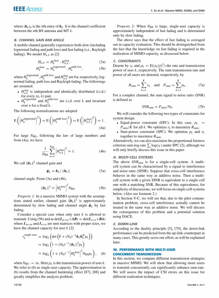
FIGURE 1. Sum-rate capacity with EPC and SPC. NBS = 64 and NMT = 1.Both slow and fast fading factors are included. Path loss is based on ahexagon cell with a normalized side length = 1. The minimum normalizeddistance between users and the BS is 35/289, corresponding to anunnormalized distance of 35m for a LTE cell with radius 289m. The lossfactor = −3.76 and lognormal fading deviation = 8 dB. The channelsamples are normalized such that the average power gain = 1. No powercontrol over slow fading.
A large K implies high transmitter and receiver costs.We need to examine carefully whether the potential benefitscan justify the cost. For this purpose, Fig. 1 shows the poten-tial sum-rate capacity gain for a single-cell system. PerfectCSI at receiver (CSIR) and perfect CSI at transmitter (CSIT)
are assumed in Fig. 1. The curves apply to both up- anddown-links following the duality principle [2], [5], [79]. Forcapacity computation, see [8].
We can make the following observations from Fig. 1:
• Multi-user gain is seen from the growth of sum-ratewith K . The potential gain is in the order of tens of timesfor both EPC and SPC.
• The difference between EPC and SPC is initially smallbut becomes noticeable when K is very large. This indi-cates the importance of resource allocation when K islarge.
Fig. 1 shows that multi-user gain is very attractive. Diver-sifying power over more users, i.e., increasing K , is a veryeffective way to increase sum-rate. Motivated by this, in whatfollows, we will discuss efficient realization techniques formulti-user gain at affordable cost.
B. ANGLE AND NEAR-FAR DIVERSITIESSpatial diversity can be further divided into angle and near-far diversities that refer to, respectively, the variations in {φk}and {||hk ||2}. The related advantages are referred to as anglegain and near-far gain respectively.
Recall that the size of H in (2) is NBS × K and the angles{φk} are normalized columns of H . Assume that {φk} arei.i.d. (See Section II-B). When K � NBS, {φk} are almostorthogonal to each other. This effectively results in K parallelinterference-free channels. Increasing K can thus increasesystem sum-rate, which leads to angle gain.
Angle diversity alone does not fully explain multi-usergain. For example, it is impossible to have more than NBSorthogonal angles when K > NBS. The variation in {||hk ||2}due to slow-fading also contributes. This is referred to as near-far diversity [2], [23], [24], [89], although it can be caused byboth block fading and path loss in massive MIMO.
Roughly speaking, angle gain can be from the EPC curvesand near-far gain from the difference between a pair of SPCand EPC curves with the same SNRsum in Fig. 1. For SPCwithhigh SNR, angle gain dominates the overall gain.
Angle gain is available only in MIMO and not in SISO.On the other hand, near-far gain is available in both MIMOand SISO. Angle and near-far gains can be achieved by bothOMA and NOMA. We will discuss various options in thefollowing subsections.
C. ZF, MRC AND MRC-SICFig. 1 is for capacity analysis. We now turn attention topractical realizations. ZF and MRC are two common options.
A ZF estimator is given by [2]:
x(j) =(HHH
)−1HHy(j). (8a)
Substituting (2a) into (8a) and letting ξ (j) = (HHH)−1HH
η(j), we have
x(j) = x(j)+ ξ (j). (8b)
VOLUME 5, 2017 14731
C. Xu et al.: Massive MIMO, NOMA, and IDMA
Clearly, x(j) can be used to estimate x(j). With ZF, differentusers are divided into different orthogonal subspaces, whichavoids interference and provides angle gain. When HHH isill-conditioned, the noise term ξ (j) = (HHH)−1HHη(j) in(8) suffers from an amplification effect [2]. Water-filling overdifferent orthogonal subspaces can be used to alleviate theproblem, which also provides near-far gain.
An MRC estimator [2] is defined in a symbol-by-symbolform as
xk (j) = hHk y(j). (9a)
Substituting (1) into (9a),
xk (j) = λkxk (j)+ ξk (j), (9b)
where λk ≡ ‖hk‖2= hHk hk is a scalar and
ξk (j) ≡K∑
k ′=1,k ′ 6=k
hHk hk ′xk ′ (j)+ hHk η(j) (9c)
is an interference (from xk ′ (j), k ′ 6= k to xk (j)) plus noiseterm.MRCdoes not involvematrix inversion and so has lowercost than ZF. However, interference is a problem for MRC,especially when K is large.MRC-SIC [24] retains the low cost of MRC while sup-
presses interference. We illustrate its principle using K = 2.Assume that the signal of user 1 is decoded first. In this case,from (9) we have
x1(j) = λ1x1(j)+ ξ1(j), (10a)
ξ1(j) = hH1 h2x2(j)+ hH1 η(j). (10b)
We treat ξ1(j) as a Gaussian additive noise. The achievablerate of user 1 based on (10) is
r1 = log2
(1+
p1‖h1‖2
p2∥∥hH1 h2∥∥2/‖h1‖2 + N0
). (11a)
After successfully decoding x1(j) , its interference is sub-tracted from y(j). We then decode x2(j) with achievable rate
r2 = log2
(1+
p2‖h2‖2
N0
). (11b)
Based on the above, we have
Rsum = log2
(1+
p1‖h1‖2
p2∥∥hH1 h2∥∥2/‖h1‖2 + N0
)
+ log2
(1+
p2‖h2‖2
N0
). (11c)
Angle gain can be seen from the correlation term∥∥hH1 h2∥∥2
in (11c) which represents interference. Its impact reducesstatistically when NBS increases.Near-far gain stems from the difference in ‖hk‖2 in
(11c) that allows room for optimization. For example, wecan adjust p1 and p2 to minimize Psum when r1 andr2 are fixed [24], [90], [91] or to maximize Rsum when
r1 and r2 are adjustable [2], [5], [92], or alternately,to maximize sum log-rate log(r1) + log(r2) for betterfairness [2], [25], [26], [93].It can be shown that MRC-SIC is asymptotically capacity
approaching in a MIMO system with K →∞ [24].We categorize MRC-SIC as NOMA since it requires MUD
(in the form of SIC) and ZF as OMA since it requires SUDonly. MRC is on the borderline: it employs SUD without spa-tial orthogonality. MRC works fine only when interference isnegligible.
D. NOMA AND ITS LIMITATION IN SISOThe following discussion provides useful insights intoNOMA and OMA. Let us consider a special case ofMRC-SIC in SISO, for which every hk reduces to a scalarhk so (11c) becomes
Rsum = log2
(1+
p1|h1|2
p2|h2|2 + N0
)+ log2
(1+
p2|h2|2
N0
).
(12a)
This is a special case of the following SISO SIC schemewith K users:
Rsum =K∑k=1
log2
1+pk |hk |2
K∑k ′=k+1
pk ′ |hk ′ |2 + N0
. (12b)
Power control (PC) can be applied over pk . The achiev-able rate by this PC-SIC scheme coincides with the capac-ity of a K -user SISO multiple-access channel (MAC) givenbelow [2], [94]
Rsum = log2
(1+
1N0
K∑k=1
pk |hk |2). (12c)
As comparison, we consider OMA under resource allo-cation. We adopt TDMA with flexible length (TDMA-FL),in which time slot lengths for different users are optimizedto maximize sum-rate [2]. We first consider equal energycontrol (EEC), in which different users have different powerlevels but their total energy per frame is the same. (Thisis possible since their transmission durations can be dif-ferent.) It is shown in [2, pp. 232–234] that TDMA-FL iscapacity achieving under EEC. This is illustrated in Fig. 2.Clearly, NOMA and OMA have the same performance inthis case. OMA is actually a simpler option since it involvesSUD only.
The situation is slightly different if the total energy perframe per user can also be freely optimized under the sum-energy constraint (SEC). For example, consider maximiz-ing sum-log-rate log(r1) + log(r2) under the proportionalfairness criterion [2]. Fig. 3 illustrates the related numerical
14732 VOLUME 5, 2017

C. Xu et al.: Massive MIMO, NOMA, and IDMA
FIGURE 2. Near-far gain by NOMA and OMA in SISO MAC under EEC.NOMA is based on SIC and OMA on TDMA-FL. TDMA with equal length(TDMA-EL) is used as reference. NBS = 1 and NMT = 1. Other systemsettings are the same as those in Fig 1.
results for K = 2 in the typical SNR range.2 The sum-rate curves in Fig. 3(a) show that PC-SIC is only slightlybetter than TDMA (about 8% over TDMA-FL and 20% overTDMA-EL at SNRsum = 10 dB). The sum-log-rate curves inFig. 3(b) indicate that all the schemes have almost the samefairness.
The multi-user gain in Figs. 2 and 3 solely comes fromnear-far diversity, since there is no angle diversity in SISO.Later in Section III-G, we will see the implications of theabove observations in MIMO.
E. COMPARISONS OF ZF, MRC AND MRC-SICFig. 4 compares different approaches under perfect CSIRwith the same channel parameters as those in Fig. 1. ForZF under SPC, resource allocation is applied through userselection [90] and water-filling [2]. For MRC-SIC with SPC,to reduce complexity, we simply adopt the same PC levels asthose obtained from capacity analysis. Decoding starts fromthe user with the highest channel gain. Unequal rate alloca-tion [2] is assumed in all the schemes compared in Fig. 4.
Following the duality principles [2], [5], [79], Fig. 4 isapplicable to both up- and down-links. Transmitter ZF andmaximum ratio transmission (MRT) are, respectively, thedown-link duals of receiver ZF and MRC [2]. The down-link dual of the up-link PC and MRC-SIC involves highlycomplicated dirty paper coding [95]. An exception is SISO,in which simple PC-SIC is capacity achieving for both links(using opposite decoding orders [2, p. 241]).
2This range is used for the following reason. In a multi-cell system, weshould consider interference from other cells. Define the SINR as
SINRsum = Psum/(N0 + Icross-cell)
where Icross-cell is the total cross-cell interference from all neighbor cells.Based on the discussion in Section II-D, we assume that other-cell interfer-ence can be approximated as additive noise and then SNRsum in a single-cellenvironment has the equivalent effect as SINRsum in a multi-cell one. At theend of Section V, we will show that 0-10 dB is a common range for SINRsumin amulti-cell system, which translates to 0-10 dB for SNRsum in a single-cellsystem.
FIGURE 3. Achievable sum-rate under SEC. (a) Average sum rate and(b) average sum log-rate for NOMA and OMA. System parameters are thesame as those in Fig. 2.
FIGURE 4. Achievable sum-rate of different approaches under perfectCSIR. System parameters are the same as those in Fig. 1. SNRsum = 5 dB.
We are not aware of a good optimization method forMRC under SPC. Therefore there is no related resultin Fig. 4.
VOLUME 5, 2017 14733

C. Xu et al.: Massive MIMO, NOMA, and IDMA
We make the following observations from Fig. 4.• MRC works fine only when K is very small.• When K is small, ZF can perform close to capacity.When K is large, however, ZF works well under SPC,but not under EPC. The problem is caused by noiseamplification discussed below (8).
• MRC-SIC performs well for all K under bothEPC and SPC.
• Angle gain can be seen from the EPC curves, whichis around ten folds for MRC-SIC. Resource allocationoffers further near-far gain. The latter can be achievedby both OMA via ZF and NOMA via MRC-SIC.
Thus, under perfect CSI, both OMA (e.g., ZF) and NOMA(e.g., MRC-SIC) can offer good multi-user gain. Using dual-ity, we expect that ZF works well in the down-link. MRT isalso an option when K is small.We expect that MRC-SIC can potentially offer good fair-
ness with proper rate and power optimization. We are stillworking on this problem.
F. NOMA VIA ZF-SICThere are more sophisticated options. In the down-linkZF-SIC schemes in [28] and [30], ZF is used to createorthogonal subspaces. The users in the same sub-space form agroup. SIC is applied to the users in each group. This ZF-SICscheme improves fairness [28], [30] but suffers from someobstacles:• Orthogonal grouping is difficult in practice. To see this,let Pr(g) be the probability of the event that the size ofa group is g. It can be shown that Pr(g) → 0 quicklywhen g increases. The probability of g ≥ 2 is usuallyvery small, which implies that the benefit of SIC is smallstatistically.
• With CSI error, cross group interference may causesevere problem during SIC.
• The cost of SIC in the down-link can be a concern.
G. OMA VIA ZF-TDMA AND TDMA-ZFNow suppose that orthogonal grouping has been done via ZFas above. We actually have a much simpler OMA alternativeby applying TDMA to the users within each group. We callthis approach ZF-TDMA. Similar to the discussions above,we have Pr(g ≥ 2) ≈ Pr(g = 2). From Fig. 3, we expect thatZF-TDMA (with FL) underperforms ZF-SIC only slightly atg = 2.3 The difference is insignificant compared with theoverall multi-user gain in the order of tens of times, as seenin Fig. 4.
3Since the users in each group have the same angle, the operationwithin each group is equivalent to SISO SIC in (12). We can thus useFigs. 2 and 3 for performance assessment. This is only an approximatetreatment since the distributions of channel gains are different for SISOand MIMO.
Also note that the difference among the curves in Fig. 3 increases withSNRsum. In a cellular system, SNRsum is limited by cross-cell interference.(See footnote 2.) For sum-rate maximization, each group has very smallprobability to be allocated with a very large sum SNR. Therefore we canfocus on the range of SNRsum in Fig. 3.
ZF-TDMA still involves orthogonal grouping. We canavoid the problem by swapping the order of ZF and TDMAas follows.• Each time frame is divided into non-overlapping slots.Each time slot is assigned with several users.
• ZF is applied to the users in each slot.We call the above TDMA-ZF. It can be categorized as OMAand requires only SUD. Judging from Fig. 3, we expect thatflexible time allocation can offer good multi-user gain as wellas improved fairness in TDMA-ZF.
H. IMPACT OF UNCERTAIN CSIRFrom Fig. 4, channel capacity can be reasonably approachedby ZF or MRC-SIC under perfect CSIR. The situation canbe very different with CSIR error. Since the related capacityanalysis is difficult, we will discuss the issue using numericalresults below.
Denote by H = {Hn,k} and 1H = {1Hn,k} two NBS × Kmatrices of i.i.d. complex Gaussian entries with zero meanand unit variance. We adopt a simplified model to character-ize CSI error [96], [97],
H =√εH +
√1− ε1H, (13)
where√εH and
√1− ε1H respectively represent the
known and unknown parts of H , and ε (0 ≤ ε ≤ 1) is aconfidence factor: ε = 0 for no CSI and ε = 1 for perfectCSI. The mean square error (MSE) of CSI is given by
MSE ≡ E[∣∣∣Hn,k −√εHn,k ∣∣∣2] = 1− ε. (14)
This relationship will be used in Section V-C.Substituting (13) into (2a), we have
y(j) =√εHx(j)+ η(j), (15a)
where
η(j) =√1− ε1Hx(j)+ η(j) (15b)
is an equivalent noise vector. Note the similarity between (2a)and (15). We can carry out simulation by treating
√εH and
η(j) as if they are, respectively, the true channel matrix andadditive noise. However, η(j) in (15b) is actually dependenton x(j). We observed considerable performance deteriorationdue to such dependency.
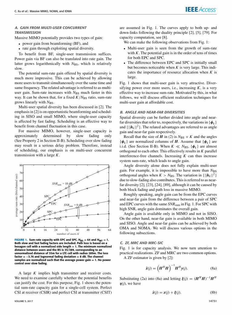
The impact of CSI error is demonstrated in Fig. 5 for dif-ferent ε values. A rate-1/3 turbo code with two convolutionalcomponent codes of generator matrix (1, 13/15)8 is used foreach user. Detailed receiver principles related to Fig. 5 willbe explained in Section IV. We can see the loss due to CSIRerror for all the schemes. The loss becomes more noticeablewhen K increases.
MRC outperforms ZF in Fig. 5 when ε = 1 (i.e., perfectCSI) which is different from the results in Fig. 4. This isbecause, for convenience of simulation, equal rate allocationis used in Fig. 5. Related discussions can be found in [98]. Theproblem can be improved by unequal rate allocation, whichis assumed in Fig. 4.
14734 VOLUME 5, 2017
C. Xu et al.: Massive MIMO, NOMA, and IDMA
FIGURE 5. The impact of CSIR error. NBS = 64 and NMT = 1. Rayleighfading. No slow fading. Rate-1/3 turbo coding. The length of informationbits of each user Jinfo = 1200. A codeword is transmitted over 10 resourceblocks. Each resource block contains 180 symbols experiencing the samefading conditions. ε = 1, 0.8 and 0.5 respectively for each scheme.Iterations process until convergence for the turbo decoder of each user.
We can also see from Fig. 5 that ZF is most sensitiveto CSI error. This is expected, since CSI error destroys theinterference free assumption in ZF. It appears that MRC-SICis the more robust one against CSI error in Fig. 5.
Using duality principles, we can also show that CSI errorhas similar impact on ZF and MRT in the down-link.
I. SUMMARY: NOMA VS OMAWenow summarize Section III. Comparing Figs. 1, 3, 4 and 5,we can make the following observations:
• Multi-user gain from increasing K is potentially verylarge.
• With accurate CSI, a major part of multi-user gain can beachieved by OMA (i.e., ZF or TDMA-ZF) with properresource allocation. The remaining gain by introducingNOMA is only incremental.
• Without accurate CSI, all existing methods performpoorly at large K .
Based on duality, the above arguments apply to both up- anddown-links.
Assume TDD. CSIR acquired from the up-link can serveas CSIT for the down-link. Then reliable up-link channelestimation holds the key to massive MIMO systems underTDD, for both NOMA and OMA. In what follows, we willshow that NOMA has an edge over OMA on this issue.
IV. IDMA AND ITERATIVE MUDFig. 4 shows that MRC-SIC can offer excellent performanceat relatively low cost in the up-link. Ideal capacity-achievingcoding and decoding are assumed there. A practical codeincurs extra loss in each SIC step. Such loss accumulatesduring the SIC process, which can result in serious overall
loss. Iterative detection outlined below can compensate forsuch loss. Iterative processing is also the core in the data aidedchannel estimation technique discussed in the next section.IDMA facilitates these iterative techniques.
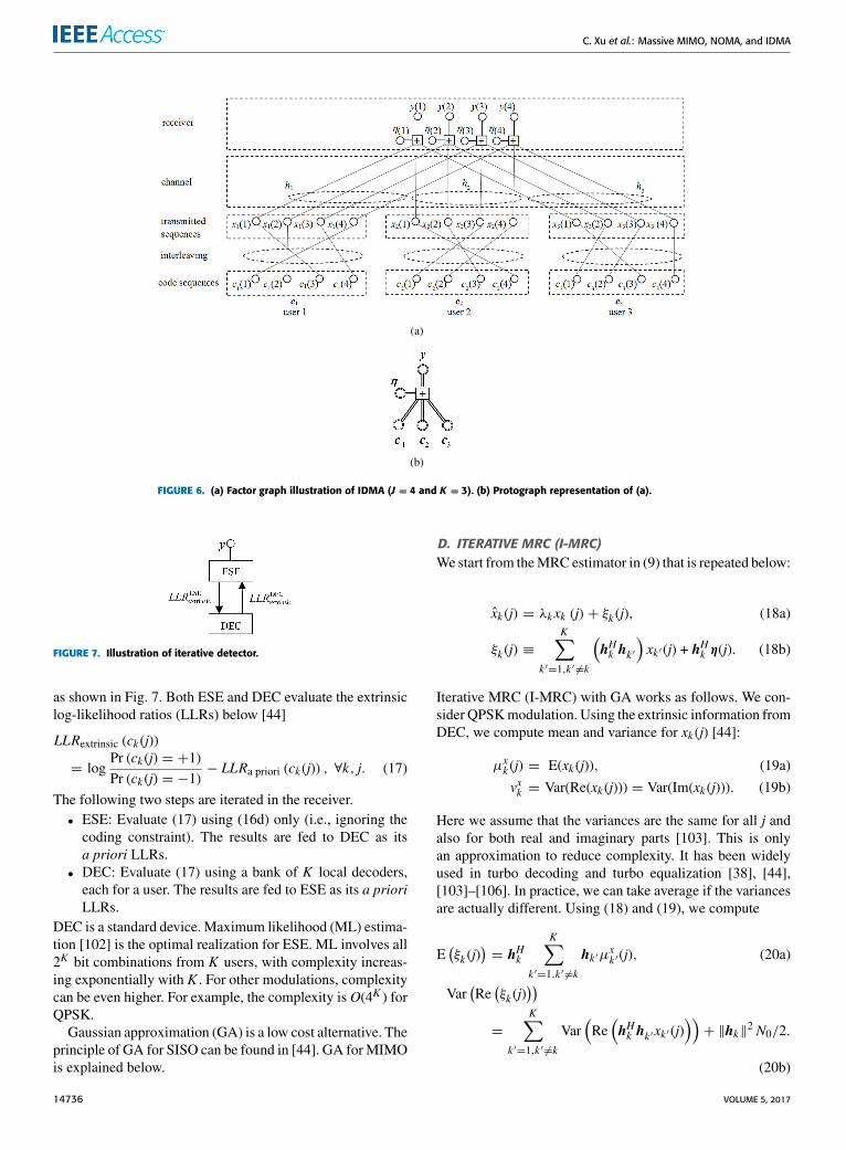
A. SPARSE GRAPHIC MODEL FOR IDMAIDMA was originally proposed through a sparse graphmodel [65]. Fig. 6(a) shows a SISO example of a 3-userIDMA system, in which a circle represents a variable and asquare marked with ‘‘+’’ represents an addition. Interleavingis represented by random edge connections. When the framelength J increases, the graph becomes more sparse, whichfacilitates iterative decoding [99], [100]. More details areexplained below.
B. IDMA TRANSMITTERFor simplicity, we first consider SISO systems. Let ck ={ck (j)} be a length-J codeword generated by users k . Assumethat ck (j) is in the binary phase shift keying (BPSK) format:ck (j) ∈ {−1,+1}. A transmitted symbol with BPSK signal-ing from user k at time j is given by [44]
xk (j) =√pkck (j′), (16a)
where√pk is a power control factor and j′ is determined by
a user-specific interleaver πk (·). Alternatively, a transmittedsymbol with quadrature phase shift keying (QPSK) signalingfrom user k at time j is given by
Re[xk (j)] =√pk/2ck (j′), (16b)
Im[xk (j)] =√pk/2ck (j′′), (16c)
where j′ and j′′ are determined by interleaving. The receivedsymbol y(j) at time j is given by
y(j) =K∑k=1
hkxk (j)+ η(j), (16d)
where hk is the channel coefficient for user k and η(j) anAWGN sample.
Fig. 6(b) is a protograph representation [101] of Fig. 6(a).Here each double circle represents a vector and each doubleline represents a vector connection. Random interleaving isimplicitly assumed for each double edge. Denote by y =[y(1), y(2), . . . , y(J )]. Note the difference between y and y(j)in (1). The former is a temporal sequence received on oneantenna and the latter a spatial sequence received on NBSantennas at time j. Similarly, denote by c and η the codedand noise sequences over time, respectively.
Fig. 6 can bemodified to represent theMIMO system in (1)by replacing y(j) and η(j) with their vector forms y(j) and η(j)for signals over multiple antennas.
C. ITERATIVE DETECTIONAn IDMA receiver consists of two local processors, namelyelementary signal estimator (ESE) and decoder (DEC) [44]
VOLUME 5, 2017 14735
C. Xu et al.: Massive MIMO, NOMA, and IDMA
FIGURE 6. (a) Factor graph illustration of IDMA (J = 4 and K = 3). (b) Protograph representation of (a).
FIGURE 7. Illustration of iterative detector.
as shown in Fig. 7. Both ESE and DEC evaluate the extrinsiclog-likelihood ratios (LLRs) below [44]
LLRextrinsic (ck (j))
= logPr (ck (j) = +1)Pr (ck (j) = −1)
− LLRa priori (ck (j)) , ∀k, j. (17)
The following two steps are iterated in the receiver.• ESE: Evaluate (17) using (16d) only (i.e., ignoring thecoding constraint). The results are fed to DEC as itsa priori LLRs.
• DEC: Evaluate (17) using a bank of K local decoders,each for a user. The results are fed to ESE as its a prioriLLRs.
DEC is a standard device. Maximum likelihood (ML) estima-tion [102] is the optimal realization for ESE. ML involves all2K bit combinations from K users, with complexity increas-ing exponentially with K . For other modulations, complexitycan be even higher. For example, the complexity is O(4K ) forQPSK.
Gaussian approximation (GA) is a low cost alternative. Theprinciple of GA for SISO can be found in [44]. GA forMIMOis explained below.
D. ITERATIVE MRC (I-MRC)We start from theMRC estimator in (9) that is repeated below:
xk (j) = λkxk (j)+ ξk (j), (18a)
ξk (j) ≡K∑
k ′=1,k ′ 6=k
(hHk hk ′
)xk ′ (j) + hHk η(j). (18b)
Iterative MRC (I-MRC) with GA works as follows. We con-sider QPSKmodulation. Using the extrinsic information fromDEC, we compute mean and variance for xk (j) [44]:
µxk (j) = E(xk (j)), (19a)
vxk = Var(Re(xk (j))) = Var(Im(xk (j))). (19b)
Here we assume that the variances are the same for all j andalso for both real and imaginary parts [103]. This is onlyan approximation to reduce complexity. It has been widelyused in turbo decoding and turbo equalization [38], [44],[103]–[106]. In practice, we can take average if the variancesare actually different. Using (18) and (19), we compute
E(ξk (j)
)= hHk
K∑k ′=1,k ′ 6=k
hk ′µxk ′ (j), (20a)
Var(Re(ξk (j)
))=
K∑k ′=1,k ′ 6=k
Var(Re(hHk hk ′xk ′ (j)
))+ ‖hk‖2 N0/2.
(20b)
14736 VOLUME 5, 2017
C. Xu et al.: Massive MIMO, NOMA, and IDMA
Let Re[xk (j)] =√pk/2ck (j′) for a certain j′ (See (16)). With
GA, we approximate ξk (j) in (18a) by a Gaussian randomvariable, so that (17) can be evaluated as [44]
LLRextrinsic(ck (j′)
)=
2λk√pk/2
Var(Re(ξk (j)
))Re (xk - E (ξk (j))) .(21)
In (21), we effectively treat (18a) as a single user model sothe detection complexity is negligible. The main complexityof I-MRC is the updating operations in (20). To reduce com-plexity, we rewrite (20a) in a sum-and-subtract form as
E(ξk (j)
)= hHk
(K∑
k ′=1
hk ′µxk ′ (j) − hkµxk (j)
). (22a)
Note that∥∥hHk hk ′∥∥2 → |H slow
k |2|H slowk ′ |2NBS, k ′ 6= k when
NBS is large. We can rewrite (20b) as
Var(Re(ξk (j)
))≈ |H slow
k |2NBS
(K∑
k ′=1
|H slowk ′ |2vxk ′ − |H
slowk |2vxk
)+ |H slow
k |2NBSN0/2. (22b)
The per user complexity in (22) does not grow with K sincethe summations in (22) can be shared by K users. Thus theoverall complexity of I-MRC is significantly lower than thatof ML. The latter grows exponentially with K .
E. RELATED SCHEMESThe following are some schemes related to IDMA.
1) POWER CONTROLSimilar to SIC in (11), we can optimize pk in (16). The userswith higher arrival powers will converge first during iterativedetection, which reduces interference to other users. Detaileddiscussions can be found in [66] and [67].
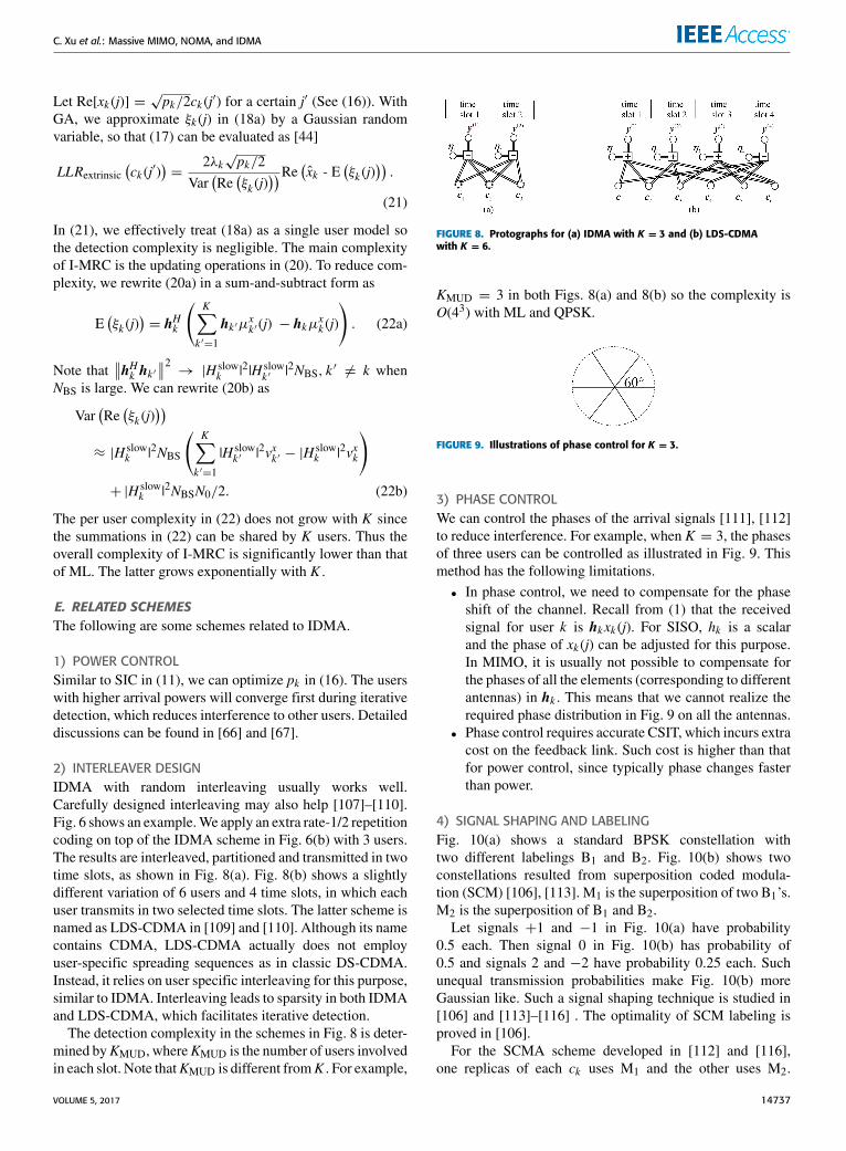
2) INTERLEAVER DESIGNIDMA with random interleaving usually works well.Carefully designed interleaving may also help [107]–[110].Fig. 6 shows an example.We apply an extra rate-1/2 repetitioncoding on top of the IDMA scheme in Fig. 6(b) with 3 users.The results are interleaved, partitioned and transmitted in twotime slots, as shown in Fig. 8(a). Fig. 8(b) shows a slightlydifferent variation of 6 users and 4 time slots, in which eachuser transmits in two selected time slots. The latter scheme isnamed as LDS-CDMA in [109] and [110]. Although its namecontains CDMA, LDS-CDMA actually does not employuser-specific spreading sequences as in classic DS-CDMA.Instead, it relies on user specific interleaving for this purpose,similar to IDMA. Interleaving leads to sparsity in both IDMAand LDS-CDMA, which facilitates iterative detection.
The detection complexity in the schemes in Fig. 8 is deter-mined byKMUD, whereKMUD is the number of users involvedin each slot. Note thatKMUD is different fromK . For example,
FIGURE 8. Protographs for (a) IDMA with K = 3 and (b) LDS-CDMAwith K = 6.
KMUD = 3 in both Figs. 8(a) and 8(b) so the complexity isO(43) with ML and QPSK.
FIGURE 9. Illustrations of phase control for K = 3.
3) PHASE CONTROLWe can control the phases of the arrival signals [111], [112]to reduce interference. For example, when K = 3, the phasesof three users can be controlled as illustrated in Fig. 9. Thismethod has the following limitations.• In phase control, we need to compensate for the phaseshift of the channel. Recall from (1) that the receivedsignal for user k is hkxk (j). For SISO, hk is a scalarand the phase of xk (j) can be adjusted for this purpose.In MIMO, it is usually not possible to compensate forthe phases of all the elements (corresponding to differentantennas) in hk . This means that we cannot realize therequired phase distribution in Fig. 9 on all the antennas.
• Phase control requires accurate CSIT, which incurs extracost on the feedback link. Such cost is higher than thatfor power control, since typically phase changes fasterthan power.
4) SIGNAL SHAPING AND LABELINGFig. 10(a) shows a standard BPSK constellation withtwo different labelings B1 and B2. Fig. 10(b) shows twoconstellations resulted from superposition coded modula-tion (SCM) [106], [113]. M1 is the superposition of two B1’s.M2 is the superposition of B1 and B2.Let signals +1 and −1 in Fig. 10(a) have probability
0.5 each. Then signal 0 in Fig. 10(b) has probability of0.5 and signals 2 and −2 have probability 0.25 each. Suchunequal transmission probabilities make Fig. 10(b) moreGaussian like. Such a signal shaping technique is studied in[106] and [113]–[116] . The optimality of SCM labeling isproved in [106].
For the SCMA scheme developed in [112] and [116],one replicas of each ck uses M1 and the other uses M2.
VOLUME 5, 2017 14737
C. Xu et al.: Massive MIMO, NOMA, and IDMA
FIGURE 10. (a) BPSK constellation with two different labelings B1 and B2.(b) SCM constellation obtained after superimposing two BPSK signalsin (a). For M1, both BPSK signals are with labelling B1. For M2, one is withB1 and the other with B2.
This scheme is effective when it is used together with phasecontrol.
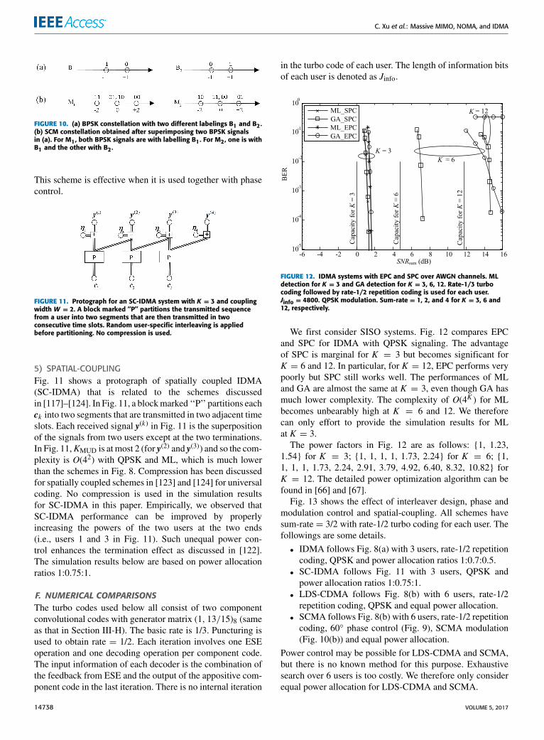
FIGURE 11. Protograph for an SC-IDMA system with K = 3 and couplingwidth W = 2. A block marked ‘‘P’’ partitions the transmitted sequencefrom a user into two segments that are then transmitted in twoconsecutive time slots. Random user-specific interleaving is appliedbefore partitioning. No compression is used.
5) SPATIAL-COUPLINGFig. 11 shows a protograph of spatially coupled IDMA(SC-IDMA) that is related to the schemes discussedin [117]–[124]. In Fig. 11, a blockmarked ‘‘P’’ partitions eachck into two segments that are transmitted in two adjacent timeslots. Each received signal y(k) in Fig. 11 is the superpositionof the signals from two users except at the two terminations.In Fig. 11,KMUD is at most 2 (for y(2) and y(3)) and so the com-plexity is O(42) with QPSK and ML, which is much lowerthan the schemes in Fig. 8. Compression has been discussedfor spatially coupled schemes in [123] and [124] for universalcoding. No compression is used in the simulation resultsfor SC-IDMA in this paper. Empirically, we observed thatSC-IDMA performance can be improved by properlyincreasing the powers of the two users at the two ends(i.e., users 1 and 3 in Fig. 11). Such unequal power con-trol enhances the termination effect as discussed in [122].The simulation results below are based on power allocationratios 1:0.75:1.
F. NUMERICAL COMPARISONSThe turbo codes used below all consist of two componentconvolutional codes with generator matrix (1, 13/15)8 (sameas that in Section III-H). The basic rate is 1/3. Puncturing isused to obtain rate = 1/2. Each iteration involves one ESEoperation and one decoding operation per component code.The input information of each decoder is the combination ofthe feedback from ESE and the output of the appositive com-ponent code in the last iteration. There is no internal iteration
in the turbo code of each user. The length of information bitsof each user is denoted as Jinfo.
FIGURE 12. IDMA systems with EPC and SPC over AWGN channels. MLdetection for K = 3 and GA detection for K = 3, 6, 12. Rate-1/3 turbocoding followed by rate-1/2 repetition coding is used for each user.Jinfo = 4800. QPSK modulation. Sum-rate = 1, 2, and 4 for K = 3, 6 and12, respectively.
We first consider SISO systems. Fig. 12 compares EPCand SPC for IDMA with QPSK signaling. The advantageof SPC is marginal for K = 3 but becomes significant forK = 6 and 12. In particular, for K = 12, EPC performs verypoorly but SPC still works well. The performances of MLand GA are almost the same at K = 3, even though GA hasmuch lower complexity. The complexity of O(4K ) for MLbecomes unbearably high at K = 6 and 12. We thereforecan only effort to provide the simulation results for MLat K = 3.The power factors in Fig. 12 are as follows: {1, 1.23,
1.54} for K = 3; {1, 1, 1, 1, 1.73, 2.24} for K = 6; {1,1, 1, 1, 1.73, 2.24, 2.91, 3.79, 4.92, 6.40, 8.32, 10.82} forK = 12. The detailed power optimization algorithm can befound in [66] and [67].
Fig. 13 shows the effect of interleaver design, phase andmodulation control and spatial-coupling. All schemes havesum-rate = 3/2 with rate-1/2 turbo coding for each user. Thefollowings are some details.• IDMA follows Fig. 8(a) with 3 users, rate-1/2 repetitioncoding, QPSK and power allocation ratios 1:0.7:0.5.
• SC-IDMA follows Fig. 11 with 3 users, QPSK andpower allocation ratios 1:0.75:1.
• LDS-CDMA follows Fig. 8(b) with 6 users, rate-1/2repetition coding, QPSK and equal power allocation.
• SCMA follows Fig. 8(b) with 6 users, rate-1/2 repetitioncoding, 60◦ phase control (Fig. 9), SCMA modulation(Fig. 10(b)) and equal power allocation.
Power control may be possible for LDS-CDMA and SCMA,but there is no known method for this purpose. Exhaustivesearch over 6 users is too costly. We therefore only considerequal power allocation for LDS-CDMA and SCMA.
14738 VOLUME 5, 2017

C. Xu et al.: Massive MIMO, NOMA, and IDMA
FIGURE 13. Comparison over AWGN channels. For all schemes,Jinfo = 4800, rate-1/2 turbo coding and sum-rate = 3/2. Iterationsprocess until convergence.
We make the following observations from Fig. 13.
• SC-IDMA offers the best performance as well asthe lowest decoding complexity of O(42) with ML(as KMUD = 2 in Fig. 11).
• Except for SC-IDMA, all other schemes haveKMUD = 3with ML complexity O(43).
• The use of GA can greatly reduce complexity. GAincurs certain performance loss. Such loss is marginalin IDMA and SC-IDMA and slightly more noticeable inLDS-CDMA and SCMA.
• Sparsity is not unique for SCMA since all the schemescompared in Fig. 13 rely on sparsity to facilitate iterativedetection. The unique features of SCMA are actuallythe special phase control, signal-shaping and labellingmethod in Figs. 9 and 10.
• The 3-user settings of IDMA and SC-IDMA are moreflexible than the 6-user settings of LDS-CDMA andSCMA.
Based on the above observations, from now onwewill onlydiscuss IDMA with GA and power control, which are simpleas well as of excellent performance. Our work on spatial-coupling is still preliminary. We will report the related resultslater.
Next we proceed to massiveMIMO systems. Fig. 14 showsthe convergence behavior of I-MRC for a 16-user IDMAsystem with fast fading only. Single-user interference-freeperformance is included as reference. As sum-rates are dif-ferent for K = 1 and K = 16, SNRsum is not a fair criterionfor comparison and so Eb/N0 is used instead in Fig. 14.We can see that, after 30 iterations, the 16-user system per-forms almost the same as the single-user one. The perfor-mance is sufficiently good after 10 iterations.
Fig. 15 illustrates the multi-user gain for K = 8 withI-MRC.Multiple signal streams are used for each user for rateadjustment [106], [115]. We consider three different settings:
FIGURE 14. I-MRC for K = 16. NBS = 64 and NMT = 1. Rayleigh fading.No slow fading. Rate-1/3 turbo coding and Jinfo = 1200. A codeword istransmitted over 10 resource blocks. Each resource block contains180 symbols experiencing the same fading conditions. Maximum iterationnumbers (denoted by It in the figure) are 1, 3, 5, 10, 20 and 30,respectively. Different interleavers are applied to the users based onIDMA. Single user interference-free performance is included as reference.
FIGURE 15. Multi-user gain for K = 8 with I-MRC. Maximum iterationnumber is 30. Equal transmit power is assumed for different users. Powercontrol is used for the streams assigned to the same user. Rate-1/2 turbocoding and Jinfo = 1200 for each stream. Other parameters and settingsare the same as those in Fig. 14.
• K = 1 and Rsum = 5 with five signal streams assignedto the sole user,
• K = 8 and Rsum = 16 with two streams per user, and• K = 8 and Rsum = 24 with three streams per user.
For K = 1, all the signal streams see the same channel sothere is no spatial diversity among them, which results in poorperformance. Increasing K from 1 to 8 results in drasticallyenhanced rate or reduced power or both in Fig. 15. Fig. 15is a compelling evidence for multi-user gain: allowing moreconcurrent transmitting users ismore efficient than increasingsingle user rate. The power allocation levels used in Fig. 15are obtained through heuristic search. We will discuss thedetailed search algorithm elsewhere.
VOLUME 5, 2017 14739

C. Xu et al.: Massive MIMO, NOMA, and IDMA
Though not shown in the figure, it is observed that inter-leaver design, phase control, modulation control and spatial-coupling can only offer marginal benefit in massive MIMO.Only power control is effective and it is applied to the systemsimulated in Fig. 15. For more details on power controlalgorithms, see [66], [67], [125], [126].
V. ITERATIVE DATA-AIDED CHANNEL ESTIMATIONIt was shown in Section III that CSI quality is crucial inmassive MIMO systems. We now discuss a data-aided chan-nel estimation (DACE) technique [19], [22], [45], [76]–[78]to improve CSI acquisition in the up-link. DACE can benaturally combined with MRC under the NOMA framework,which provides an efficient solution to massive MIMO.
A. DACEThe correlation among the pilots used by different userscan lead to considerable performance degradation. This isreferred to as the pilot contamination problem [16]. DACE isanalyzed in [22] for this problem. DACE can be used jointlywith MRC, which involves the iteration of following twooperations:• using partially decoded data as pilots to refine channelestimation and
• using improved channel estimates to refine data estima-tion using MRC.
Data sequences are typically much longer than pilots, socorrelation is low among them. DACE increases the effectivepilot power as well as reduces pilot contamination [22].
The principle of DACE is outlined as follows. We dividea transmitted signal frame of length J into blocks, each oflength J ′, and add K pilot symbols into each block. The totallength of each block becomes J ′ + K . Assume that channelcoefficients remain unchanged in each block. For each block,the received signals of data symbols at the nth antenna canbe rewritten in form of time sequences according to (2) asbelow.
yn =K∑k=1
Hn,kxk + ηn, (23a)
where
yn = [yn(1), · · · , yn(j), · · · , yn(J ′)]T , (23b)
xk = [xk (1), · · · , xk (j), · · · , xk (J ′)]T , (23c)
ηn = [ηn(1), · · · , ηn(j), · · · , ηn(J ′)]T . (23d)
Here yn(j), xk (j) and ηn(j) are, respectively, entries of y(j), x(j)and η(j) in (2). Let {xk = E(xk ),∀k} be the DEC feedbacks
and{Hn,k = E(Hn,k ),∀n, k
}be obtained from the previous
iteration that are known to the receiver. For user k , we canthus compute
zn,k = yn −K∑
k ′=1,k ′ 6=k
Hn,k ′ xk ′ . (24)
Substituting (23a) into (24), we have
zn,k = xkHn,k + ξn,k , (25a)
where
ξn,k = Hn,k · (xk − xk)
+
K∑k ′=1,k ′ 6=k
(Hn,k ′xk ′ − Hn,k ′ xk ′
)+ ηn (25b)
is an equivalent noise term. We can see that the opera-tion in (24) is to minimize the power of ξn,k by cancelingthe interference from other users. Assume that
{ξn,k (j) ,∀j
}(the entries of ξn,k ) are i.i.d. with zero mean and varianceV ξn,k = E(|ξn,k (j) |2). For each block, user k is assigned witha unique length-K pilot sequence pk that is orthogonal to thepilot sequences of other users in the same cell. Thus usersare free from same-cell pilot interference. Let zpilotn,k be thepilot sequence observation of user k at the nth antenna. TheLMMSE estimation of Hn,k based on (25) is given by
Hn,k =
pHk zpilotn,kN0+
xHk zn,kV ξn,k
1|H slow
k |2+
pHk pkN0+
xHk xkV ξn,k
. (26)
Some details on (26) can be found in the Appendix.The advantages of DACE are two folds:
(i) With DACE, the estimated data are gradually used tohelp pilot for channel estimation. Pilot energy can begreatly reduced since only very coarse CSI is requiredinitially.
(ii) DACE is robust against pilot contamination that iscaused by the correlation among the pilot sequencesused by different users [22].Without DACE, longer pilotsequences will be required to reduce such correlation.Thus DACE also reduces the time overhead related topilots.
B. SYMMETRIC AND ASYMMETRIC TRAFFIC FLOWSIn some services, such as speech, each user occupies both-up and down-links with symmetric traffic flows. In this case,under TDD, the CSI estimated at the BS is shared for bothlinks, so is the advantage of DACE.4
Many applications have asymmetric traffics in the twolinks. For example, a user downloading a file may not uploadanything at the same time. In this case, uploading-only users
4Here are some details. Consider estimating CSI using a pilot togetheran up-link codeword U. The estimated CSI is used to transmit a down-link codeword D. Assume that each codeword is transmitted over multiplecoherent resource blocks with different fading realizations. Also assumethat channel estimation and decoding are carried out after collecting all theobservations of U. For casuality, U must be transmitted entirely before Din time. This can be ensured by arranging all the blocks of U on differentsubcarriers at the same time, followed by all the blocks of D.
From Property 2, there is no need for resource allocation over frequency inmassive MIMO. (Spatial water-filling is still useful in ZF.) Thus transmittingeach codeword with equal power across subcarriers at the same time does notcompromise efficiency.
14740 VOLUME 5, 2017
C. Xu et al.: Massive MIMO, NOMA, and IDMA
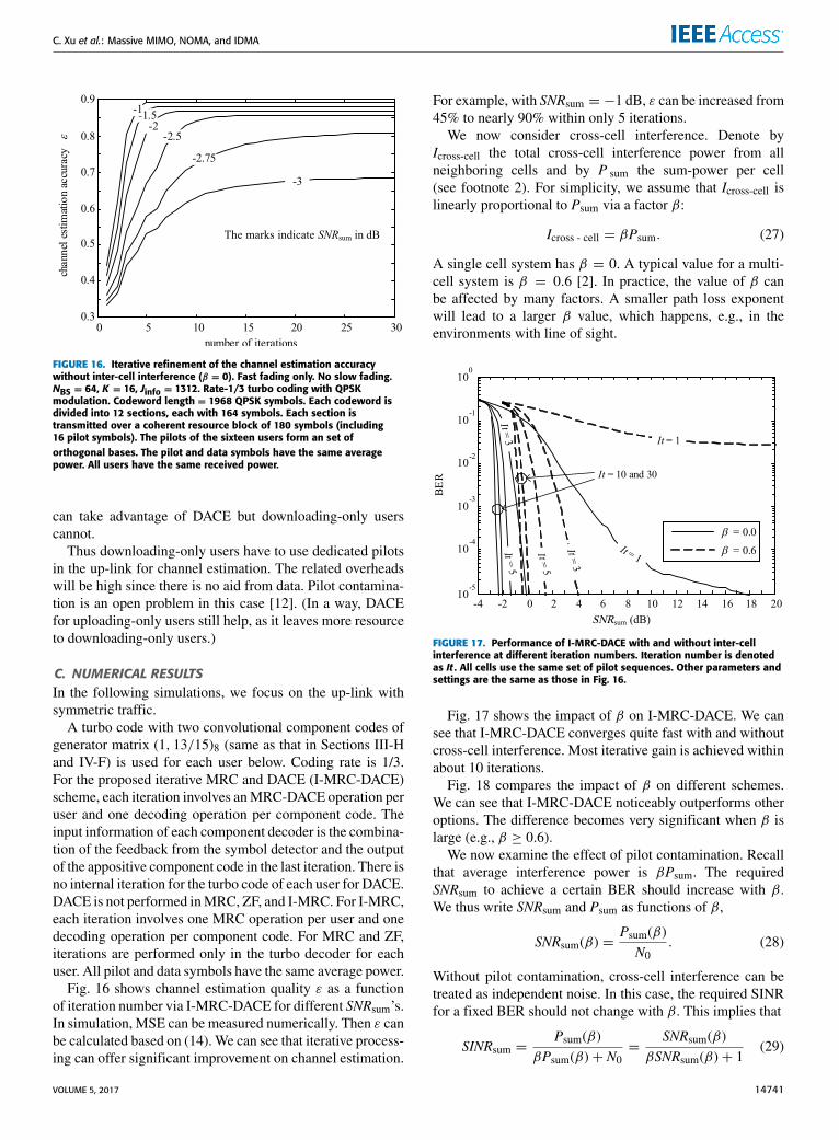
FIGURE 16. Iterative refinement of the channel estimation accuracywithout inter-cell interference (β = 0). Fast fading only. No slow fading.NBS = 64, K = 16, Jinfo = 1312. Rate-1/3 turbo coding with QPSKmodulation. Codeword length = 1968 QPSK symbols. Each codeword isdivided into 12 sections, each with 164 symbols. Each section istransmitted over a coherent resource block of 180 symbols (including16 pilot symbols). The pilots of the sixteen users form an set oforthogonal bases. The pilot and data symbols have the same averagepower. All users have the same received power.
can take advantage of DACE but downloading-only userscannot.
Thus downloading-only users have to use dedicated pilotsin the up-link for channel estimation. The related overheadswill be high since there is no aid from data. Pilot contamina-tion is an open problem in this case [12]. (In a way, DACEfor uploading-only users still help, as it leaves more resourceto downloading-only users.)
C. NUMERICAL RESULTSIn the following simulations, we focus on the up-link withsymmetric traffic.
A turbo code with two convolutional component codes ofgenerator matrix (1, 13/15)8 (same as that in Sections III-Hand IV-F) is used for each user below. Coding rate is 1/3.For the proposed iterative MRC and DACE (I-MRC-DACE)scheme, each iteration involves anMRC-DACE operation peruser and one decoding operation per component code. Theinput information of each component decoder is the combina-tion of the feedback from the symbol detector and the outputof the appositive component code in the last iteration. There isno internal iteration for the turbo code of each user for DACE.DACE is not performed inMRC, ZF, and I-MRC. For I-MRC,each iteration involves one MRC operation per user and onedecoding operation per component code. For MRC and ZF,iterations are performed only in the turbo decoder for eachuser. All pilot and data symbols have the same average power.
Fig. 16 shows channel estimation quality ε as a functionof iteration number via I-MRC-DACE for different SNRsum’s.In simulation, MSE can be measured numerically. Then ε canbe calculated based on (14). We can see that iterative process-ing can offer significant improvement on channel estimation.
For example, with SNRsum = −1 dB, ε can be increased from45% to nearly 90% within only 5 iterations.
We now consider cross-cell interference. Denote byIcross-cell the total cross-cell interference power from allneighboring cells and by P sum the sum-power per cell(see footnote 2). For simplicity, we assume that Icross-cell islinearly proportional to Psum via a factor β:
Icross - cell = βPsum. (27)
A single cell system has β = 0. A typical value for a multi-cell system is β = 0.6 [2]. In practice, the value of β canbe affected by many factors. A smaller path loss exponentwill lead to a larger β value, which happens, e.g., in theenvironments with line of sight.
FIGURE 17. Performance of I-MRC-DACE with and without inter-cellinterference at different iteration numbers. Iteration number is denotedas It . All cells use the same set of pilot sequences. Other parameters andsettings are the same as those in Fig. 16.
Fig. 17 shows the impact of β on I-MRC-DACE. We cansee that I-MRC-DACE converges quite fast with and withoutcross-cell interference. Most iterative gain is achieved withinabout 10 iterations.
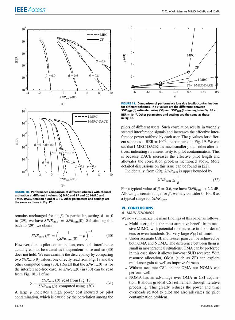
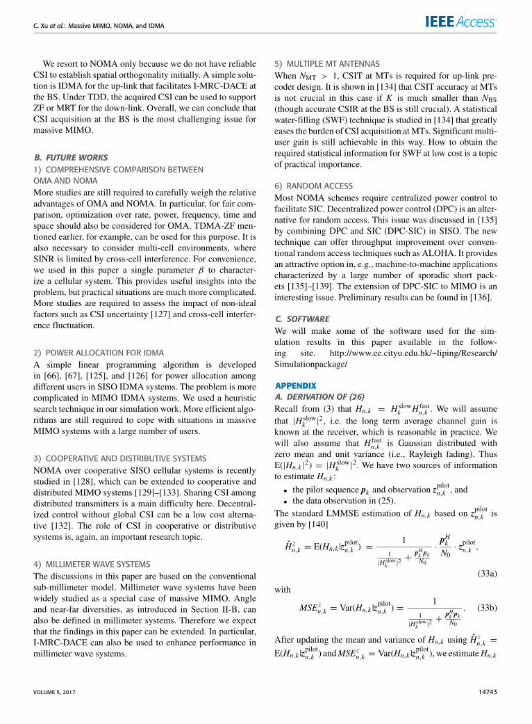
Fig. 18 compares the impact of β on different schemes.We can see that I-MRC-DACE noticeably outperforms otheroptions. The difference becomes very significant when β islarge (e.g., β ≥ 0.6).We now examine the effect of pilot contamination. Recall
that average interference power is βPsum. The requiredSNRsum to achieve a certain BER should increase with β.We thus write SNRsum and Psum as functions of β,
SNRsum(β) =Psum(β)N0
. (28)
Without pilot contamination, cross-cell interference can betreated as independent noise. In this case, the required SINRfor a fixed BER should not change with β. This implies that
SINRsum =Psum(β)
βPsum(β)+ N0=
SNRsum(β)βSNRsum(β)+ 1
(29)
VOLUME 5, 2017 14741
C. Xu et al.: Massive MIMO, NOMA, and IDMA
FIGURE 18. Performance comparison of different schemes with channelestimation at different β values: (a) MRC and ZF and (b) I-MRC andI-MRC-DACE. Iteration number = 10. Other parameters and settings arethe same as those in Fig. 17.
remains unchanged for all β. In particular, setting β = 0in (29), we have SINRsum = SNRsum(0). Substituting thisback to (29), we obtain
SNRsum (β) =(
1SNRsum (0)
− β
)−1. (30)
However, due to pilot contamination, cross-cell interferenceactually cannot be treated as independent noise and so (30)does not hold. We can examine the discrepancy by comparingtwo SNRsum(β) values: one directly read from Fig. 18 and theother computed using (30). (Recall that the SNRsum(0) is forthe interference-free case, so SNRsum(0) in (30) can be readfrom Fig. 18.) Define
γ =SNRsum (β) read from Fig. 18
SNRsum (β) computed using (30). (31)
A large γ indicates a high power cost incurred by pilotcontamination, which is caused by the correlation among the
FIGURE 19. Comparison of performance loss due to pilot contaminationfor different schemes. The γ values are the difference betweenSNR sum(β) estimated using (30) and SNRsum(β) reading from Fig. 18 atBER = 10−5. Other parameters and settings are the same as thosein Fig. 18.
pilots of different users. Such correlation results in wronglysteered interference signals and increases the effective inter-ference power suffered by each user. The γ values for differ-ent schemes at BER= 10−5 are compared in Fig. 19. We cansee that I-MRC-DACE hasmuch smaller γ than other alterna-tives, indicating its insensitivity to pilot contamination. Thisis because DACE increases the effective pilot length andalleviates the correlation problem mentioned above. Moredetailed discussions on this issue can be found in [22].
Incidentally, from (29), SINRsum is upper bounded by
SINRsum ≤1β. (32)
For a typical value of β = 0.6, we have SINRsum ≈ 2.2 dB.Allowing a certain range for β, we may consider 0–10 dB asa typical range for SINRsum.
VI. CONCLUSIONSA. MAIN FINDINGSWenow summarize themain findings of this paper as follows.• Multi-user gain is the most attractive benefit from mas-sive MIMO, with potential rate increase in the order oftens or even hundreds (for very large NBS) of times.
• Under accurate CSI, multi-user gain can be achieved byboth OMA and NOMA. The difference between them issmall in most practical situations. OMA can be preferredin this case since it allows low-cost SUD receiver. Withresource allocation, OMA (such as ZF) can exploremulti-user gain as well as improve fairness.
• Without accurate CSI, neither OMA nor NOMA canperform well.
• NOMA has an advantage over OMA in CSI acquisi-tion. It allows gradual CSI refinement through iterativeprocessing. This greatly reduces the power and timeoverheads related to pilot and also alleviates the pilotcontamination problem.
14742 VOLUME 5, 2017
C. Xu et al.: Massive MIMO, NOMA, and IDMA
We resort to NOMA only because we do not have reliableCSI to establish spatial orthogonality initially. A simple solu-tion is IDMA for the up-link that facilitates I-MRC-DACE atthe BS. Under TDD, the acquired CSI can be used to supportZF or MRT for the down-link. Overall, we can conclude thatCSI acquisition at the BS is the most challenging issue formassive MIMO.
B. FUTURE WORKS1) COMPREHENSIVE COMPARISON BETWEENOMA AND NOMAMore studies are still required to carefully weigh the relativeadvantages of OMA and NOMA. In particular, for fair com-parison, optimization over rate, power, frequency, time andspace should also be considered for OMA. TDMA-ZF men-tioned earlier, for example, can be used for this purpose. It isalso necessary to consider multi-cell environments, whereSINR is limited by cross-cell interference. For convenience,we used in this paper a single parameter β to character-ize a cellular system. This provides useful insights into theproblem, but practical situations are much more complicated.More studies are required to assess the impact of non-idealfactors such as CSI uncertainty [127] and cross-cell interfer-ence fluctuation.
2) POWER ALLOCATION FOR IDMAA simple linear programming algorithm is developedin [66], [67], [125], and [126] for power allocation amongdifferent users in SISO IDMA systems. The problem is morecomplicated in MIMO IDMA systems. We used a heuristicsearch technique in our simulation work. More efficient algo-rithms are still required to cope with situations in massiveMIMO systems with a large number of users.
3) COOPERATIVE AND DISTRIBUTIVE SYSTEMSNOMA over cooperative SISO cellular systems is recentlystudied in [128], which can be extended to cooperative anddistributed MIMO systems [129]–[133]. Sharing CSI amongdistributed transmitters is a main difficulty here. Decentral-ized control without global CSI can be a low cost alterna-tive [132]. The role of CSI in cooperative or distributivesystems is, again, an important research topic.
4) MILLIMETER WAVE SYSTEMSThe discussions in this paper are based on the conventionalsub-millimeter model. Millimeter wave systems have beenwidely studied as a special case of massive MIMO. Angleand near-far diversities, as introduced in Section II-B, canalso be defined in millimeter systems. Therefore we expectthat the findings in this paper can be extended. In particular,I-MRC-DACE can also be used to enhance performance inmillimeter wave systems.
5) MULTIPLE MT ANTENNASWhen NMT > 1, CSIT at MTs is required for up-link pre-coder design. It is shown in [134] that CSIT accuracy at MTsis not crucial in this case if K is much smaller than NBS(though accurate CSIR at the BS is still crucial). A statisticalwater-filling (SWF) technique is studied in [134] that greatlyeases the burden of CSI acquisition atMTs. Significant multi-user gain is still achievable in this way. How to obtain therequired statistical information for SWF at low cost is a topicof practical importance.
6) RANDOM ACCESSMost NOMA schemes require centralized power control tofacilitate SIC. Decentralized power control (DPC) is an alter-native for random access. This issue was discussed in [135]by combining DPC and SIC (DPC-SIC) in SISO. The newtechnique can offer throughput improvement over conven-tional random access techniques such as ALOHA. It providesan attractive option in, e.g., machine-to-machine applicationscharacterized by a large number of sporadic short pack-ets [135]–[139]. The extension of DPC-SIC to MIMO is aninteresting issue. Preliminary results can be found in [136].
C. SOFTWAREWe will make some of the software used for the sim-ulation results in this paper available in the follow-ing site. http://www.ee.cityu.edu.hk/~liping/Research/Simulationpackage/
APPENDIXA. DERIVATION OF (26)Recall from (3) that Hn,k = H slow
k H fastn,k . We will assume
that |H slowk |
2, i.e. the long term average channel gain isknown at the receiver, which is reasonable in practice. Wewill also assume that H fast
n,k is Gaussian distributed withzero mean and unit variance (i.e., Rayleigh fading). ThusE(|Hn,k |2) = |H slow
k |2. We have two sources of information
to estimate Hn,k :
• the pilot sequence pk and observation zpilotn,k , and• the data observation in (25).
The standard LMMSE estimation of Hn,k based on zpilotn,k isgiven by [140]
H zn,k = E(Hn,k |z
pilotn,k ) =
1
1|H slow
k |2+
pHk pkN0
·pHkN0· zpilotn,k ,
(33a)
with
MSEzn,k = Var(Hn,k |zpilotn,k ) =
1
1|H slow
k |2+
pHk pkN0
. (33b)
After updating the mean and variance of Hn,k using H zn,k =
E(Hn,k |zpilotn,k ) andMSEzn,k = Var(Hn,k |z
pilotn,k ), we estimateHn,k
VOLUME 5, 2017 14743
C. Xu et al.: Massive MIMO, NOMA, and IDMA
again using xk . Using [140, eq. (11.33)], we have
Hn,k = H zn,k +
1
1MSEzn,k
+xHk xkV ξn,k
·xHkV ξn,k·
(zn,k − xk H z
n,k
).
(34)
Substituting (33) into (34) gives (26).
B. VARIANCE COMPUTATIONOn the right hand side of (26), all the variables are available
except V ξn,k = E(|ξn,k (j) |2). We now briefly explain how toapproximately compute V ξn,k in real time. We treat ξn,k asa zero-mean additive noise vector. From (25b), for each j,we have
V ξn,k = E(∣∣Hn,k ∣∣2) · E (∣∣xk (j)− xk (j)∣∣2)+
K∑k ′ 6=k
E(∣∣∣Hn,k ′xk ′ (j)− Hn,k ′ xk ′ (j)∣∣∣2)+ N0. (35)
Here xk ′ (j) is the feedback from the DEC and Hn,k ′ isobtained from the previous iteration. As mentioned above,E(|Hn,k |2) = |H slow
k |2 is assumed known. E(|xk (j)− xk (j) |
2)is the variance of xk (j) feedback from the DEC and can becomputed similarly as (19b) in Subsection IV-D. The term inthe summation in (35) can be rewritten as
E(∣∣∣Hn,k ′xk ′ (j)− Hn,k ′ xk ′ (j)∣∣∣2)
= E(∣∣1Hn,k ′ xk ′ (j)+ Hn,k ′1xk ′ ∣∣2) , (36)
where 1Hn,k ′ = Hn,k ′ − Hn,k ′ and 1xk ′ = xk ′ (j)− xk ′ (j).Consider a standard linear model y = hx + η. Define
MMSE estimation x ≡ E (x|y) and error 1x ≡ x − x.It is known that 1x is uncorrelated with both h and x [140].Base on this, we assume that 1Hn,k ′ , 1xk ′ , xk ′ (j) and Hn,k ′are approximately uncorrelated with each other. We furtherassume that they are approximately Gaussian. Then they areindependent of each other as well. We then have
E(∣∣∣Hn,k ′xk ′ (j)− Hn,k ′ xk ′ (j)∣∣∣2)= E
(∣∣1Hn,k ′ ∣∣2)E (∣∣xk ′ (j)∣∣2)+E (∣∣Hn,k ′ ∣∣2)E (|1xk ′ |2) .(37)
The terms on the right hand side of (37) can be generatedas follows. Assume that V ξn,k ′ is obtained from the previousiteration. Then E(|1Hn,k ′ |2) can be obtained as the MSE forestimating Hn,k ′ [140],
E(∣∣1Hn,k ′ ∣∣2) = MSE =
1
1|H slow
k |2+
pHk pkN0+
xHk′xk′
V ξn,k′
. (38)
For E(|xk ′ (j) |2), we use approximation
E(∣∣xk ′ (j)∣∣2) ≈ 1
J
J∑j=1
∣∣xk ′ (j)∣∣2. (39)
Finally, from (19b), we have E(|1xk ′ |2
)= Var(Re(xk ′ (j)))+
Var(Im(xk ′ (j))) ≈ 2vxk for QPSK modulation. Note that V ξn,kserves as a weighting factor for the data observation in (25).From simulation, we observed that DACE is not sensitive tothe accuracy of V ξn,k .
ACKNOWLEDGEMENTThe last author would also like to thank Keying Wu,Jinhong Yuan, Yi Hong, Emmanuel Viterbo,Jiangzhou Wang, Cheng-Xiang Wang, Kit K. Wong,Peter Hoeher, Lin Dai and Moshe Zukerman for enlighteningdiscussions during the writing up of this paper.
REFERENCES[1] E. Telatar, ‘‘Capacity of multi-antenna Gaussian channels,’’ Eur. Trans.
Telecommun., vol. 10, no. 6, pp. 585–595, Nov./Dec. 1999.[2] D. N. C. Tse and P. Viswanath, Fundamentals Wireless Communication.
Cambridge, U.K.: Cambridge Univ. Press, 2005.[3] V. Tarokh, N. Seshadri, and A. R. Calderbank, ‘‘Space-time codes for
high data rate wireless communication: Performance criterion and codeconstruction,’’ IEEE Trans. Inf. Theory, vol. 44, no. 2, pp. 744–765,Mar. 1998.
[4] P. Viswanath, D. N. C. Tse, and V. Anantharam, ‘‘Asymptotically opti-mal water-filling in vector multiple-access channels,’’ IEEE Trans. Inf.Theory, vol. 47, no. 1, pp. 241–267, Jan. 2001.
[5] S. Vishwanath, N. Jindal, and A. Goldsmith, ‘‘Duality, achievable rates,and sum-rate capacity of Gaussian MIMO broadcast channels,’’ IEEETrans. Inf. Theory, vol. 49, no. 10, pp. 2658–2668, Oct. 2003.
[6] W. Yu, W. Rhee, S. Boyd, and J. M. Cioffi, ‘‘Iterative water-filling forGaussian vector multiple-access channels,’’ IEEE Trans. Inf. Theory,vol. 50, no. 1, pp. 145–152, Jan. 2004.
[7] H. Weingarten, Y. Steinberg, and S. Shamai (Shitz), ‘‘The capacity regionof the Gaussian multiple-input multiple-output broadcast channel,’’ IEEETrans. Inf. Theory, vol. 52, no. 9, pp. 3936–3964, Sep. 2006.
[8] M. Kobayashi and G. Caire, ‘‘An iterative water-filling algorithm formaximum weighted sum-rate of Gaussian MIMO-BC,’’ IEEE J. Sel.Areas Commun., vol. 24, no. 8, pp. 1640–1646, Aug. 2006.
[9] J. Mietzner, R. Schober, L. Lampe, W. H. Gerstacker, and P. A. Hoeher,‘‘Multiple-antenna techniques for wireless communications—A compre-hensive literature survey,’’ IEEE Commun. Surveys Tuts., vol. 11, no. 2,pp. 87–105, 2nd Quart., 2009.
[10] G. Caire, N. Jindal, M. Kobayashi, and N. Ravindran, ‘‘Multiuser MIMOachievable rates with downlink training and channel state feedback,’’IEEE Trans. Inf. Theory, vol. 56, no. 6, pp. 2845–2866, Jan. 2010.
[11] D. Gesbert, S. Hanly, H. Huang, S. S. Shitz, O. Simeone, and W. Yu,‘‘Multi-cell MIMO cooperative networks: A new look at interference,’’IEEE J. Sel. Areas Commun., vol. 28, no. 9, pp. 1380–1408, Dec. 2010.
[12] T. L. Marzetta, ‘‘Noncooperative cellular wireless with unlimited num-bers of base station antennas,’’ IEEE Trans. Wireless Commun., vol. 9,no. 11, pp. 3590–3600, Nov. 2010.
[13] J. Jose, A. Ashikhmin, T. L. Marzetta, and S. Vishwanath, ‘‘Pilot contam-ination and precoding in multi-cell TDD systems,’’ IEEE Trans. WirelessCommun., vol. 10, no. 8, pp. 2640–2651, Aug. 2011.
[14] F. Rusek et al., ‘‘Scaling up MIMO: Opportunities and challenges withvery large arrays,’’ IEEE Signal Process. Mag., vol. 30, no. 1, pp. 40–60,Jan. 2013.
[15] J. Hoydis, S. ten Brink, andM.Debbah, ‘‘MassiveMIMO in theUL/DL ofcellular networks: How many antennas do we need?’’ IEEE J. Sel. AreasCommun., vol. 31, no. 2, pp. 160–171, Feb. 2013.
14744 VOLUME 5, 2017

C. Xu et al.: Massive MIMO, NOMA, and IDMA
[16] E. G. Larsson, O. Edfors, F. Tufvesson, and T. L. Marzetta, ‘‘MassiveMIMO for next generation wireless systems,’’ IEEE Commun. Mag.,vol. 52, no. 2, pp. 186–195, Feb. 2014.
[17] L. Lu, G. Y. Li, A. L. Swindlehurst, A. Ashikhmin, and R. Zhang,‘‘An overview of massive MIMO: Benefits and challenges,’’ IEEE J. Sel.Topics Signal Process., vol. 8, no. 5, pp. 742–758, Oct. 2014.
[18] P. Hoeher and N. Doose, ‘‘A massive MIMO terminal concept basedon small-size multi-mode antennas,’’ Trans. Emerging Telecommun.Technol., vol. 28, no. 2, Feb. 2017.
[19] P. Hoeher and F. Tufvesson, ‘‘Channel estimation with superimposedpilot sequence,’’ in Proc. IEEE GLOBECOM, vol. 4. Dec. 1999,pp. 2162–2166.
[20] J. Vieira, F. Rusek, and F. Tufvesson, ‘‘Reciprocity calibration methodsfor massive MIMO based on antenna coupling,’’ in Proc. IEEE GlobalCommun. Conf. (GLOBECOM), Dec. 2014, pp. 3708–3712.
[21] A. Ashikhmin and T. Marzetta, ‘‘Pilot contamination precoding in multi-cell large scale antenna systems,’’ in Proc. IEEE ISIT, Cambridge, MA,USA, Jul. 2012, pp. 1137–1141.
[22] J. Ma and L. Ping, ‘‘Data-aided channel estimation in large antennasystems,’’ IEEE Trans. Signal Process., vol. 62, no. 12, pp. 3111–3124,Jun. 2014.
[23] P. Wang, J. Xiao, and L. Ping, ‘‘Comparison of orthogonal and non-orthogonal approaches to future wireless cellular systems,’’ IEEE Veh.Technol. Mag., vol. 1, no. 3, pp. 4–11, Sep. 2006.
[24] P. Wang and L. Ping, ‘‘On maximum eigenmode beamforming and multi-user gain,’’ IEEE Trans. Inf. Theory, vol. 57, no. 7, pp. 4170–4180,Jul. 2011.
[25] N. Otao, Y. Kishiyama, and K. Higuchi, ‘‘Performance of non-orthogonalaccess with SIC in cellular downlink using proportional fairbasedresource allocation,’’ in Proc. IEEE ISWCS, Paris, France, Aug. 2012,pp. 476–480.
[26] J. Umehara, Y. Kishiyama, and K. Higuchi, ‘‘Enhancing user fairnessin non-orthogonal access with successive interference cancellation forcellular downlink,’’ in Proc. IEEE ICCS, Munich, Germany, Nov. 2012,pp. 324–328.
[27] Y. Saito, Y. Kishiyama, A. Benjebbour, T. Nakamura, A. Li, andK. Higuchi, ‘‘Non-orthogonal multiple access (NOMA) for cellular futureradio access,’’ in Proc. IEEE VTC-Spring, Dresden, Germany, Jun. 2013,pp. 1–5.
[28] B. Kim et al., ‘‘Non-orthogonal multiple access in a downlinkmultiuser beamforming system,’’ in Proc. IEEE Military Commun.Conf. (MILCOM), Nov. 2013, pp. 1278–1283.
[29] K. Higuchi and A. Benjebbour, ‘‘Non-orthogonal multiple access(NOMA) with successive interference cancellation for future radioaccess,’’ IEICE Trans. Commun., vol. E98–B, no. 3, pp. 403–414,Mar. 2015.
[30] Z. Ding, F. Adachi, and H. V. Poor, ‘‘The application of MIMO to non-orthogonal multiple access,’’ IEEE Trans. Wireless Commun., vol. 15,no. 1, pp. 537–552, Jan. 2016.
[31] Z. Ding, P. Fan, and H. V. Poor, ‘‘Impact of user pairing on 5Gnonorthogonal multiple access,’’ IEEE Trans. Veh. Technol., vol. 65, no. 8,pp. 6010–6023, Aug. 2016.
[32] Z. Wei, D. W. K. Ng, and J. Yuan. (2016). ‘‘Power-efficient resourceallocation for MC-NOMA with statistical channel state information.’’[Online]. Available: https://arxiv.org/abs/1607.01116
[33] S. Verdu,Multiuser Detection. Cambridge, U.K.: Cambridge Univ. Press,1998.
[34] R. Lupas and S. Verdu, ‘‘Linearmultiuser detectors for synchronous code-division multiple-access channels,’’ IEEE Trans. Inf. Theory, vol. 35,no. 1, pp. 123–136, Jan. 1989.
[35] P. Hoeher, ‘‘On channel coding and multiuser detection for DS-CDMA,’’in Proc. IEEE Int. Conf. Univ. Pers. Commun., Ottawa, ON, Canada,Oct. 1993, pp. 641–646.
[36] M. Moher, ‘‘An iterative multiuser decoder for near-capacity communi-cations,’’ IEEE Trans. Commun., vol. 46, no. 7, pp. 870–880, Jul. 1998.
[37] M. C. Reed, C. B. Schlegel, P. D. Alexander, and J. A. Asenstorfer,‘‘Iterative multi-user detection for CDMA with FEC: Near-single-userperformance,’’ IEEE Trans. Commun., vol. 46, no. 12, pp. 1693–1699,Dec. 1998.
[38] X. Wang and H. V. Poor, ‘‘Iterative (turbo) soft interference cancellationand decoding for coded CDMA,’’ IEEE Trans. Commun., vol. 47, no. 7,pp. 1046–1061, Jul. 1999.
[39] F. N. Brannstrom, T.M.Aulin, and L. K. Rasmussen, ‘‘Iterativemulti-userdetection of trellis code multiple access using a posteriori probabilities,’’in Proc. IEEE ICC, vol. 1. Jun. 2001, pp. 11–15.
[40] T. Yoo and A. Goldsmith, ‘‘On the optimality of multiantenna broad-cast scheduling using zero-forcing beamforming,’’ IEEE J. Sel. AreasCommun., vol. 24, no. 3, pp. 528–541, Mar. 2006.
[41] K. S. Gilhousen, I. M. Jacobs, R. Padovani, A. J. Viterbi, L. A.Weaver, Jr.,and C. E. Wheatley, III, ‘‘On the capacity of a cellular CDMA system,’’IEEE Trans. Veh. Technol., vol. 40, no. 2, pp. 303–312, May 1991.
[42] F. Adachi, M. Sawahashi, and H. Suda, ‘‘Wideband DS-CDMA fornext generation mobile communications systems,’’ IEEE Commun. Mag.,vol. 36, no. 9, pp. 56–69, Sep. 1998.
[43] M. Peng,W.Wang, andH.-H. Chen, ‘‘TD-SCDMAevolution,’’ IEEEVeh.Technol. Mag., vol. 5, no. 2, pp. 28–41, Jun. 2010.
[44] L. Ping, L. Liu, K. Wu, and W. K. Leung, ‘‘Interleave-division multipleaccess,’’ IEEE Trans. Wireless Commun., vol. 5, no. 4, pp. 938–947,Apr. 2006.
[45] H. Schoeneich and P. Hoeher, ‘‘Iterative pilot-layer aided channelestimation with emphasis on interleave-division multiple access sys-tems,’’ EURASIP J. Appl. Signal Process., vol. 2006, pp. 1–15,Jan. 2006.
[46] Y. Hong and L. K. Rasmussen, ‘‘Iterative switched decoding forinterleave-division multiple-access systems,’’ IEEE Trans. Veh.Technol., vol. 57, no. 3, pp. 1939–1944, May 2008.
[47] B. Senanayake, M. C. Reed, and Z. Shi, ‘‘Timing acquisition formulti-user IDMA,’’ in Proc. IEEE ICC, Beijing, China, May 2008,pp. 5077–5081.
[48] R. Zhang and L. Hanzo, ‘‘Three design aspects of multicarrier interleavedivision multiple access,’’ IEEE Trans. Veh. Technol., vol. 57, no. 6,pp. 3607–3617, Nov. 2008.
[49] X. Xiong, J. Hu, F. Yang, and X. Ling, ‘‘Effect of channel estimationerror on the performance of interleave-division multiple access systems,’’in Proc. IEEE 11th ICACT, Feb. 2009, pp. 1538–1542.
[50] T. Yang, J. Yuan, and Z. Shi, ‘‘Rate optimization for IDMA systemswith iterative joint multi-user decoding,’’ IEEE Trans. Wireless Commun.,vol. 8, no. 3, pp. 1148–1153, Mar. 2009.
[51] B. Cristea, D. Roviras, and B. Escrig, ‘‘Turbo receivers for interleave-division multiple-access systems,’’ IEEE Trans. Commun., vol. 57, no. 7,pp. 2090–2097, Jul. 2009.
[52] H. Chung, Y.-C. Tsai, and M.-C. Lin, ‘‘IDMA using non-gray labelledmodulation,’’ IEEE Trans. Commun., vol. 59, no. 9, pp. 2492–2501,Sep. 2011.
[53] K. Kusume, G. Bauch, and W. Utschick, ‘‘IDMA vs. CDMA: Analysisand comparison of two multiple access schemes,’’ IEEE Trans. WirelessCommun., vol. 11, no. 1, pp. 78–87, Jan. 2012.
[54] P. Hammarberg and F. Rusek, ‘‘Channel estimation algorithms forOFDM-IDMA: Complexity and performance,’’ IEEE Trans. WirelessCommun., vol. 11, no. 5, pp. 1722–1732, May 2012.
[55] I. M. Mahafeno, C. Langlais, and C. Jego, ‘‘OFDM-IDMA versus IDMAwith ISI cancellation for quasistatic Rayleigh fading multipath channels,’’in Proc. 4th Int. Symp. Turbo Codes Rel. Topics, Munich, Germany,Apr. 2006, pp. 1–6.
[56] C. Novak, G. Matz, and F. Hlawatsch, ‘‘IDMA for the multiuserMIMO-OFDM uplink: A factor graph framework for joint data detectionand channel estimation,’’ IEEE Trans. Signal Process., vol. 61, no. 16,pp. 4051–4066, Aug. 2013.
[57] K. Wu, K. Anwar, and T. Matsumoto, ‘‘BICM-ID-based IDMA usingextended mapping,’’ IEICE Trans. Commun., vols. E97–B, no. 7,pp. 1483–1492, Jul. 2014.
[58] L. Liu, Y. Li, Y. Su, and Y. Sun, ‘‘Quantize-and-forward strategy forinterleave-division multiple-access relay channel,’’ IEEE Trans. Veh.Technol., vol. 65, no. 3, pp. 1808–1814, Mar. 2016.
[59] L. Bing, T. Aulin, B. Bai, and H. Zhang, ‘‘Design and performanceanalysis of multiuser CPM with single user detection complexity,’’ IEEETrans. Wireless Commun., vol. 15, no. 6, pp. 4032–4044, Jun. 2016.
[60] G. Song and J. Cheng, ‘‘Distance enumerator analysis for interleave-division multi-user codes,’’ IEEE Trans. Inf. Theory, vol. 62, no. 7,pp. 4039–4053, Jul. 2016.
[61] C. Berrou, A. Glavieux, and P. Thitimajshima, ‘‘Near Shannon limiterror-correcting coding and decoding: Turbo-codes. 1,’’ in Proc. IEEEInt. Conf. Commun. (ICC), vol. 2. Geneva, Switzerland, May 1993,pp. 1064–1070.
VOLUME 5, 2017 14745

C. Xu et al.: Massive MIMO, NOMA, and IDMA
[62] D. J. C. MacKay and R. M. Neal, ‘‘Near Shannon limit performance oflow density parity check codes,’’ Electron. Lett., vol. 32, no. 18, p. 1645,Aug. 1996.
[63] S. Lin and J. D. J. Costello, Error Control Coding: Fundamentals andApplications, 2nd ed. Upper Saddle River, NJ, USA: Prentice-Hall,2004.
[64] T. Richardson and R. Urbanke, Modern Coding Theory. Cambridge,U.K.: Cambridge Univ. Press, 2008.
[65] L. Ping, L. Liu, and W. K. Leung, ‘‘A simple approach to near-optimalmultiuser detection: Interleaver-division multiple-access,’’ in Proc. IEEEWCNC, New Orleans, LA, USA, Mar. 2003, pp. 391–396.
[66] L. Ping and L. Liu, ‘‘Analysis and design of IDMA systems based on SNRevolution and power allocation,’’ in Proc. IEEE VTC-Fall, Los Angeles,CA, USA, Sep. 2004, pp. 1068–1072.
[67] L. Liu, J. Tong, and L. Ping, ‘‘Analysis and optimization of CDMA sys-tems with chip-level interleavers,’’ IEEE J. Sel. Areas Commun., vol. 24,no. 1, pp. 141–150, Jan. 2006.
[68] L. Hanzo, M. El-Hajjar, and O. Alamri, ‘‘Near-capacity wirelesstransceivers and cooperative communications in the MIMO era: Evolu-tion of standards, waveform design, and future perspectives,’’Proc. IEEE,vol. 99, no. 8, pp. 1343–1385, Aug. 2011.
[69] G. Wunder et al., ‘‘5GNOW: Non-orthogonal, asynchronous waveformsfor future mobile applications,’’ IEEE Commun. Mag., vol. 52, no. 2,pp. 97–105, Feb. 2014.
[70] A. Osseiran et al., ‘‘Scenarios for 5G mobile and wireless communica-tions: The vision of the METIS project,’’ IEEE Commun. Mag., vol. 52,no. 5, pp. 26–35, May 2014.
[71] V. Jungnickel et al., ‘‘The role of small cells, coordinated multipoint, andmassive MIMO in 5G,’’ IEEE Commun. Mag., vol. 52, no. 5, pp. 44–51,May 2014.
[72] J. G. Andrews et al., ‘‘What will 5G be?’’ IEEE J. Sel. Areas Commun.,vol. 32, no. 6, pp. 1065–1082, Jun. 2014.
[73] Sparse Code Multiple Access (SCMA) for 5G Radio Transmission, doc-ument R1-162155, Huawei, HiSilicon, 3GPP TSG RAN WG1 Meeting,Busan, Korea, Apr. 2016.
[74] Non-Orthogonal Multiple Access Candidate for NR,document R1-163992, Samsung, 3GPP TSG RAN WG1 Meeting,Nanjing, China, May 2016.
[75] Uplink Contentionbased Access in 5G New Radio, document R1-165022,Nokia, Alcatel-Lucent Shanghai Bell, 3GPP TSG RAN WG1 Meeting,Nanjing, China, May 2016.
[76] P. Li, L. Liu, K. Wu, and W. Leung, ‘‘Interleave division multiple access(IDMA) communication systems,’’ in Proc. 3rd Int. Symp. Turbo CodesRel. Topics, Brest, France, Sep. 2003, pp. 173–180.
[77] M. Zhao, Z. Shi, and M. C. Reed, ‘‘Iterative turbo channel estimationfor OFDM system over rapid dispersive fading channel,’’ IEEE Trans.Wireless Commun., vol. 7, no. 8, pp. 3174–3184, Aug. 2008.
[78] C.-K. Wen, C.-J. Wang, S. Jin, K.-K. Wong, and P. Ting, ‘‘Bayes-optimaljoint channel-and-data estimation for massive MIMO with low-precisionADCs,’’ IEEE Trans. Signal Process., vol. 64, no. 10, pp. 2541–2556,May 2016.
[79] W. Yu, ‘‘Uplink-downlink duality via minimax duality,’’ IEEE Trans. Inf.Theory, vol. 52, no. 2, pp. 361–374, Feb. 2006.
[80] S. Hur, T. Kim, D. J. Love, J. V. Krogmeier, T. A. Thomas, and A. Ghosh,‘‘Millimeter wave beamforming for wireless backhaul and access in smallcell networks,’’ IEEE Trans. Commun., vol. 61, no. 10, pp. 4391–4403,Oct. 2013.
[81] O. El Ayach, S. Rajagopal, S. Abu-Surra, Z. Pi, and R. W. Heath,Jr., ‘‘Spatially sparse precoding in millimeter wave MIMO systems,’’IEEE Trans. Wireless Commun., vol. 13, no. 3, pp. 1499–1513,Mar. 2014.
[82] P. Wang, Y. Li, X. Yuan, L. Song, and B. Vucetic, ‘‘Tens of gigabitswireless communications over E-band LoSMIMO channels with uniformlinear antenna arrays,’’ IEEE Trans. Wireless Commun., vol. 13, no. 7,pp. 3791–3805, Jul. 2014.
[83] P. Wang, Y. Li, L. Song, and B. Vucetic, ‘‘Multi-gigabit millimeterwave wireless communications for 5G: From fixed access to cellularnetworks,’’ IEEE Commun. Mag., vol. 53, no. 1, pp. 168–178, Jan. 2015.
[84] H. Ghauch, T. Kim, M. Bengtsson, and M. Skoglund, ‘‘Subspace esti-mation and decomposition for large millimeter-wave MIMO systems,’’IEEE J. Sel. Topics Signal Process., vol. 10, no. 3, pp. 528–542,Apr. 2016.
[85] R. W. Heath, N. Gonzalez-Prelcic, S. Rangan, W. Roh, and A. M. Sayeed,‘‘An overview of signal processing techniques formillimeter waveMIMOsystems,’’ IEEE J. Sel. Topics Signal Process., vol. 10, no. 3, pp. 436–453,Apr. 2016.
[86] X. Wu et al., ‘‘60 GHz millimeter-wave channel measurements and mod-eling for indoor office environments,’’ IEEE Trans. Antennas Propag.,vol. 65, no. 4, pp. 1912–1924, Apr. 2017.
[87] B. Hochwald, T. Marzetta, and V. Tarokh, ‘‘Multi-antenna channel-hardening and its implications for rate feedback and scheduling,’’ IEEETrans. Inf. Theory, vol. 50, no. 9, pp. 1893–1909, Sep. 2004.
[88] M. Mohseni, R. Zhang, and J. M. Cioffi, ‘‘Optimized transmissionof fading multiple-access and broadcast channels with multiple anten-nas,’’ IEEE J. Sel. Areas Commun., vol. 24, no. 8, pp. 1627–1639,Aug. 2006.
[89] C. Yang, W. Wang, Y. Qian, and X. Zhang, ‘‘A weighted proportionalfair scheduling to maximize best-effort service utility in multicell net-work,’’ in Proc. IEEE 19th Int. Symp. Pers., Indoor Mobile RadioCommun. (PIMRC), Sep. 2008, pp. 1–5.
[90] J. Lee and N. Jindal, ‘‘Symmetric capacity of MIMO downlinkchannels,’’ in Proc. IEEE ISIT, Washington, DC, USA, Jul. 2006,pp. 1031–1035.
[91] C. Hellings, M. M. Joham, M. Riemensberger, and W. Utschick, ‘‘Min-imal transmit power in parallel vector broadcast channels with linearprecoding,’’ IEEE Trans. Signal Process., vol. 60, no. 4, pp. 1890–1898,Apr. 2012.
[92] P. Viswanath and D. N. C. Tse, ‘‘Sum capacity of the vector Gaussianbroadcast channel and uplink-downlink duality,’’ IEEE Trans. Inf. Theory,vol. 49, no. 8, pp. 1912–1921, Aug. 2003.
[93] H. Huh, S.-H. Moon, Y.-T. Kim, I. Lee, and G. Caire, ‘‘Multi-cell MIMOdownlink with cell cooperation and fair scheduling: A large-system limitanalysis,’’ IEEE Trans. Inf. Theory, vol. 57, no. 12, pp. 7771–7786,Dec. 2011.
[94] T.M. Cover and J. A. Thomas,Elements of Information Theory. Hoboken,NJ, USA: Wiley, 2006.
[95] N. Jindal and A. Goldsmith, ‘‘Dirty paper coding versus TDMA forMIMO broadcast channels,’’ IEEE Trans. Inf. Theory, vol. 51, no. 5,pp. 1783–1794, May 2005.
[96] A. Goldsmith, S. A. Jafar, N. Jindal, and S. Vishwanath, ‘‘Capacitylimits of MIMO channels,’’ IEEE J. Sel. Areas Commun., vol. 51, no. 6,pp. 684–702, Jun. 2003.
[97] T. Yoo and A. Goldsmith, ‘‘Capacity and power allocation for fadingMIMO channels with channel estimation error,’’ IEEE Trans. Inf. Theory,vol. 52, no. 5, pp. 2203–2214, May 2006.
[98] M. Joham, W. Utschick, and J. A. Nossek, ‘‘Linear transmit processing inMIMO communications systems,’’ IEEE Trans. Signal Process., vol. 53,no. 8, pp. 2700–2712, Aug. 2005.
[99] N. Wiberg, H.-A. Loeliger, and R. Kotter, ‘‘Codes and iterative decod-ing on general graphs,’’ Eur. Trans. Telecomm., vol. 6, pp. 513–525,Sep./Oct. 1995.
[100] F. R. Kschischang, B. J. Frey, and H.-A. Loeliger, ‘‘Factor graphs andthe sum-product algorithm,’’ IEEE Trans. Inf. Theory, vol. 47, no. 2,pp. 498–519, Feb. 2001.
[101] J. Thorpe, ‘‘Low-density parity-check (LDPC) codes constructed fromprotographs,’’ INP, Pasadena, CA, USA, Tech. Rep. 42-154, Aug. 2003,pp. 1–7.
[102] M. Noemm, T. Wo, and P. Hoeher, ‘‘Multilayer app detection for IDM,’’Electron. Lett., vol. 46, no. 1, pp. 96–97, Jan. 2010.
[103] J. Tong, L. Ping, Z. Zhang, and V. K. Bhargava, ‘‘Iterative soft com-pensation for OFDM systems with clipping and superposition codedmodulation,’’ IEEE Trans. Commun., vol. 58, no. 10, pp. 2861–2870,Oct. 2010.
[104] C. Douillard et al., ‘‘Iterative correction of intersymbol interference:Turbo-equalization,’’ Eur. Trans. Telecommun., vol. 6, no. 5, pp. 507–511,Sep. 1995.
[105] G. Caire, G. Taricco, and E. Biglieri, ‘‘Bit-interleaved codedmodulation,’’IEEE Trans. Inf. Theory, vol. 44, no. 3, pp. 927–946, May 1998.
[106] L. Ping, J. Tong, X. Yuan, and Q. Guo, ‘‘Superposition coded modulationand iterative linear MMSE detection,’’ IEEE J. Sel. Areas Commun.,vol. 27, no. 6, pp. 995–1004, Aug. 2009.
[107] I. Pupeza, A. Kavcic, and L. Ping, ‘‘Efficient generation of inter-leavers for IDMA,’’ in Proc. IEEE ICC, Istanbul, Turkey, Jun. 2006,pp. 1508–1513.
14746 VOLUME 5, 2017
C. Xu et al.: Massive MIMO, NOMA, and IDMA
[108] D. Hao and P. A. Hoeher, ‘‘Helical interleaver set design for interleave-division multiplexing and related techniques,’’ IEEE Commun. Lett.,vol. 12, no. 11, pp. 843–845, Nov. 2008.
[109] R. Hoshyar, F.Wathan, and R. Tafazolli, ‘‘Novel low-density signature forsynchronous CDMA systems over AWGN channel,’’ IEEE Trans. SignalProcess., vol. 56, no. 4, pp. 1616–1626, Apr. 2008.
[110] J. van de Beek and B. Popovi, ‘‘Multiple access with low-density signa-tures,’’ in Proc. IEEE ICC, Dresden, Germany, Jun. 2009, pp. 1–6.
[111] P. Hoeher, H. Schoeneich, and J. C. Fricke, ‘‘Multi-layer interleave-division multiple access: Theory and practice,’’ Eur. Trans. Telecommun.,vol. 19, no. 5, pp. 523–536, Aug. 2008.
[112] H. Nikopour andH. Baligh, ‘‘Sparse codemultiple access,’’ inProc. IEEE24th Int. Symp. Pers. IndoorMobile Radio Commun. (PIMRC), Sep. 2013,pp. 332–336.
[113] X. Ma and L. Ping, ‘‘Coded modulation using superimposed binarycodes,’’ IEEE Trans. Inf. Theory, vol. 50, no. 12, pp. 3331–3343,Dec. 2004.
[114] T. Yang and J. Yuan, ‘‘Performance of iterative decoding for superposi-tion modulation-based cooperative transmission,’’ IEEE Trans. WirelessCommun., vol. 9, no. 1, pp. 51–59, Jan. 2010.
[115] P. A. Hoeher and T. Wo, ‘‘Superposition modulation: Myths and facts,’’IEEE Commun. Mag., vol. 49, no. 12, pp. 110–116, Dec. 2011.
[116] M. Taherzadeh, H. Nikopour, A. Bayesteh, and H. Baligh, ‘‘SCMAcodebook design,’’ in Proc. IEEE 80th Veh. Technol. Conf. (VTC Fall),Sep. 2014, pp. 1–5.
[117] S. Kudekar, T. J. Richardson, and R. L. Urbanke, ‘‘Threshold satu-ration via spatial coupling: Why convolutional LDPC ensembles per-form so well over the BEC,’’ IEEE Trans. Inf. Theory, vol. 57, no. 2,pp. 803–834, Feb. 2011.
[118] K. Takeuchi, T. Tanaka, and T. Kawabata, ‘‘Improvement of BP-basedCDMA multiuser detection by spatial coupling,’’ in Proc. IEEE ISIT,Saint-Petersburg, Russian, Aug. 2011, pp. 1489–1493.
[119] Z. Zhang, C. Xu, and L. Ping, ‘‘Spatially coupled LDPC codingand linear precoding for MIMO systems,’’ IEICE Trans. Commun.,vol. E95-B, no. 12, pp. 3663–3670, Dec. 2012.
[120] C. Schlegel and D. Truhachev, ‘‘Multiple access demodulation in thelifted signal graph with spatial coupling,’’ IEEE Trans. Inf. Theory,vol. 59, no. 4, pp. 2459–2470, Apr. 2013.
[121] D. J. Costello, L. Dolecek, T. Fuja, J. Kliewer, D. Mitchell, andR. Smarandache, ‘‘Spatially coupled sparse codes on graphs: Theory andpractice,’’ IEEE Commun. Mag., vol. 52, no. 7, pp. 168–176, Jul. 2014.
[122] S. Kumar, A. J. Young, N. Macris, and H. D. Pfister, ‘‘Threshold satura-tion for spatially coupled LDPC and LDGM codes on BMS channels,’’IEEE Trans. Inf. Theory, vol. 60, no. 12, pp. 7389–7415, Dec. 2014.
[123] C. Liang, J. Ma, and L. Ping, ‘‘Towards Gaussian capacity, universalityand short block length,’’ in Proc. 9th Int. Symp. Turbo Codes, Brest,France, Sep. 2016, pp. 412–416.
[124] C. Liang, J. Ma, and L. Ping, ‘‘Compressed FEC codes with spatial-coupling,’’ IEEE Commun. Lett., vol. 21, no. 5, pp. 987–990, May 2017.
[125] P. Wang, L. Ping, and L. Liu, ‘‘Power allocation for multiple accesssystems with practical coding and iterative multi-user detection,’’ in Proc.IEEE ICC, Istanbul, Turkey, Dec. 2007, pp. 3179–3183.
[126] P. Wang and L. Ping, ‘‘On multi-user gain in MIMO systems withrate constraints,’’ in Proc. IEEE GLOBECOM, Washington, DC, USA,Dec. 2007, pp. 3179–3183.
[127] E. A. Gharavol, Y.-C. Liang, and K. Mouthaan, ‘‘Robust downlink beam-forming in multiuser MISO cognitive radio networks with imperfectchannel-state information,’’ IEEE Trans. Veh. Technol., vol. 59, no. 6,pp. 2852–2860, Jun. 2010.
[128] W. Shin, M. Vaezi, B. Lee, D. J. Love, J. Lee, and H. V. Poor.(2016). ‘‘Non-orthogonal multiple access in multi-cell networks: The-ory, performance, and practical challenges.’’ [Online]. Available:https://arxiv.org/abs/1611.01607
[129] J. Wang, F. Adachi, and X. Xia, ‘‘Coordinated and distributed MIMO,’’IEEE Wireless Commun., vol. 17, no. 3, pp. 24–25, Jun. 2010.
[130] W.W. L. Ho, T. Q. S. Quek, S. Sun, and R.W. Heath, ‘‘Decentralized pre-coding for multicell MIMO downlink,’’ IEEE Trans. Wireless Commun.,vol. 10, no. 6, pp. 1798–1809, Jun. 2011.
[131] P. Wang, H. Wang, L. Ping, and X. Lin, ‘‘On the capacity of MIMOcellular systems with base station cooperation,’’ IEEE Trans. WirelessCommun., vol. 10, no. 11, pp. 3720–3731, Nov. 2011.
[132] J. Zhang, X. Yuan, and L. Ping, ‘‘Hermitian precoding for distributedMIMO systems with individual channel state information,’’ IEEE J. Sel.Areas Commun., vol. 31, no. 2, pp. 241–250, Feb. 2013.
[133] J. Wang and L. Dai, ‘‘Downlink rate analysis for virtual-cell basedlarge-scale distributed antenna systems,’’ IEEE Trans.Wireless Commun.,vol. 15, no. 3, pp. 1998–2011, Mar. 2016.
[134] C. Xu, P. Wang, Z. Zhang, and L. Ping, ‘‘Transmitter design foruplink MIMO systems with antenna correlation,’’ IEEE Trans. WirelessCommun., vol. 14, no. 4, pp. 1772–1784, Apr. 2015.
[135] C. Xu, L. Ping, P. Wang, S. Chan, and X. Lin, ‘‘Decentralized powercontrol for random access with successive interference cancellation,’’IEEE J. Sel. Areas Commun., vol. 31, no. 11, pp. 2387–2396, Nov. 2013.
[136] C. Xu, X. Wang, and L. Ping, ‘‘Random access with massive-antennaarrays,’’ in Proc. IEEE VTC-Spring, Nanjing, China, May 2016, pp. 1–5.
[137] L. Lu, L. You, and S. C. Liew, ‘‘Network-coded multiple access,’’ IEEETrans. Mobile Comput., vol. 13, no. 12, pp. 2853–2869, Dec. 2014.
[138] H. Lin, K. Ishibashi, W.-Y. Shin, and T. Fujii, ‘‘A simple random accessscheme with multilevel power allocation,’’ IEEE Commun. Lett., vol. 19,no. 12, pp. 2118–2121, Dec. 2015.
[139] M. Zou, S. Chan, H. Vu, and L. Ping, ‘‘Throughput improvement of802.11 networks via randomization of transmission power levels,’’ IEEETrans. Veh. Technol., vol. 65, no. 4, pp. 2703–2714, Apr. 2016.
[140] S. M. Kay, Fundamentals Statistical Signal Processing: Estimation The-ory. Upper Saddle River, NJ, USA: Prentice-Hall, 1993.
CHONGBIN XU received the B.S. degree in infor-mation engineering from Xi’an Jiaotong Univer-sity in 2005 and the Ph.D. degree in informationand communication engineering from TsinghuaUniversity in 2012. Since 2014, he has beenwith the Department of Communication Scienceand Engineering, Fudan University, China. Hisresearch interests are in the areas of signal process-ing and communication theory, including linearprecoding, iterative detection, and random accesstechniques.
YANG HU received the B.S. degree from TianjinUniversity, China, in 2011, and the M.S. degreefrom Tsinghua University, China, in 2014. He iscurrently pursuing the Ph.D. degree at the CityUniversity of Hong Kong. His research interestsinclude information theory, multiuser detection,and random access techniques.
CHULONG LIANG received the B.E. degreein communication engineering and the Ph.D.degree in communication and information systemsfrom Sun Yat-sen University, Guangzhou, China,in 2010 and 2015, respectively. He is currentlya Post-Doctoral Fellow with the City Universityof Hong Kong, Hong Kong. His current researchinterests include channel coding theory and itsapplications to communication systems.
VOLUME 5, 2017 14747
C. Xu et al.: Massive MIMO, NOMA, and IDMA
JUNJIE MA received the B.E. degree from Xid-ian University, China, in 2010, and the Ph.D.degree from the City University of Hong Kongin 2015. He was a Research Fellow with theDepartment of Electronic Engineering, City Uni-versity of Hong Kong, from 2015 to 2016. Since2016, he has been a Post-Doctoral Researcher withthe Department of Statistics, Columbia Univer-sity. His current research interests include statis-tical signal processing, compressed sensing, andoptimization methods.
LI PING (S’87–M’91–SM’06–F’10) received thePh.D. degree from Glasgow University in 1990.He was a Lecturer with the Department of Elec-tronic Engineering, Melbourne University, from1990 to 1992, and a Member of Research Staffwith Telecom Australia Research Laboratoriesfrom 1993 to 1995. He has been with the Depart-ment of Electronic Engineering, City University ofHong Kong, since 1996, where he is currently aChair Professor. He served as a member of Board
of Governors of the IEEE Information Theory Society from 2010 to 2012.He was the recipient of a British Telecom-Royal Society Fellowship in 1986,the IEE J. J. Thomson Premium in 1993, the Croucher Foundation Awardin 2005, and a British Royal Academy of Engineering Distinguished VisitingFellowship in 2010.
14748 VOLUME 5, 2017