INVITATION TO TENDER (ITT) NO.: 1220-020-2015-001 · This Invitation To Tender (ITT) ... Control...
43
PURCHASING SECTION 13450 – 104 Avenue, Surrey, B.C. V3T 1V8 Tel: 604-590-7274 Fax: 604-599-0956 E-mail: [email protected] ADDENDUM NO. 1 INVITATION TO TENDER (ITT) NO.: 1220-020-2015-001 TITLE: District Energy System Phase 2a: Distribution Piping System (DPS), Energy Transfer Stations (ETS) and Containerized Boiler Plant (CBP) Service Connections ADDENDUM ISSUE DATE: June 16, 2015 CLOSING DATE: ON OR BEFORE THE FOLLOWING DATE AND TIME (THE “CLOSING TIME”): TENDER CLOSING TIME: 11:00 AM LOCAL TIME REVISED TENDER CLOSING DATE: JUNE 23, 2015 INFORMATION FOR CONTRACTORS The following information is provided to the potential tenderers for the above named project, to the extent referenced and shall become a part thereof. No consideration will be allowed for extras due to the tenderer or any sub-contractor not being familiar with this addendum. This Invitation To Tender (ITT) addendum shall form part of the Contract Documents and is to be read, interpreted and coordinated with all other parts. The following revisions supersede the information contained in the original instructions and specifications issued for the above named project. This Addendum No. 1 contains forty-three (43) pages in total. Revised Closing Date: on or before: Tender Closing Time: 11:00 am local time Revised Closing Date: June 23, 2015 CLARIFICATIONS 1. Please find enclosed the following updated Drawings: • C02-G01 – Cover Sheet • C02-C01 – TEC Site Plan • C02-C02 – DES - Whalley Blvd Plan & Profile (1) • C02-C03 – DES - Whalley Blvd Plan & Profile (2) ITT 1220-020-2015-001 - Addendum No. 1 1 of 43
Transcript of INVITATION TO TENDER (ITT) NO.: 1220-020-2015-001 · This Invitation To Tender (ITT) ... Control...

PURCHASING SECTION
13450 – 104 Avenue, Surrey, B.C. V3T 1V8 Tel: 604-590-7274 Fax: 604-599-0956
E-mail: [email protected]
ADDENDUM NO. 1
INVITATION TO TENDER (ITT) NO.:
1220-020-2015-001
TITLE:
District Energy System Phase 2a: Distribution Piping System (DPS), Energy Transfer Stations (ETS) and Containerized Boiler Plant (CBP) Service Connections
ADDENDUM ISSUE DATE:
June 16, 2015
CLOSING DATE:
ON OR BEFORE THE FOLLOWING DATE AND TIME (THE “CLOSING TIME”): TENDER CLOSING TIME: 11:00 AM LOCAL TIME
REVISED TENDER CLOSING DATE: JUNE 23, 2015
INFORMATION FOR CONTRACTORS
The following information is provided to the potential tenderers for the above named project, to the extent referenced and shall become a part thereof. No consideration will be allowed for extras due to the tenderer or any sub-contractor not being familiar with this addendum. This Invitation To Tender (ITT) addendum shall form part of the Contract Documents and is to be read, interpreted and coordinated with all other parts. The following revisions supersede the information contained in the original instructions and specifications issued for the above named project. This Addendum No. 1 contains forty-three (43) pages in total. Revised Closing Date: on or before: Tender Closing Time: 11:00 am local time Revised Closing Date: June 23, 2015 CLARIFICATIONS 1. Please find enclosed the following updated Drawings:
• C02-G01 – Cover Sheet • C02-C01 – TEC Site Plan • C02-C02 – DES - Whalley Blvd Plan & Profile (1) • C02-C03 – DES - Whalley Blvd Plan & Profile (2)
ITT 1220-020-2015-001 - Addendum No. 1 1 of 43

• C02-C04 – DES - Whalley Blvd Plan & Profile (3) • C02-C05 – DES - 100th Ave Plan & Profile • C02-C06 – TEC Site Sections • C02-C07 – Standard Details (1) • C02-C08 – Standard Details (2) • C02-C09 – Standard Details (3) • C02-C10 – Standard Details (4) • C02-C11 – Details (5) • C02-S01 – TEC Concrete Pad Details • C02-M01 – TEC Pipe Penetration Details • C02-M02 – Energy Transfer Station - Concord Phase 1 • C02-M03 – Energy Transfer Station - Concord Phase 2 • C02-E01 – Control Conduit Plan and TEC Electrical Plan • C02-E02 – Electrical Schematic - Concord Buildings
2. Please find enclosed an updated Schedule of Prices and associated Description of Payment Items.
3. Please find enclosed an update for Section 01120 – Equipment List
4. Please note the following change to the Cash Allowance amounts.
Description of Cash Allowance Amounts
Supply of Logstor Piping $450,000
Unknown Utility Conflicts $50,000
Traffic Management $150,000 QUESTION AND ANSWER Q1. Can you advise if the pre-stressing has to be complete in phases?
A1. Pre-stressing as a requirement has been removed in this Addendum
Q2. Can you advise what the Traffic restrictions/Traffic Control Requirements on Whalley
Boulevard and 100 Avenue? Will Whalley Boulevard be a live street during construction?
A2. There will be normal traffic activity on both Whalley Boulevard and 100 Avenue during
construction. The selected contractor will be required to develop and implement a
traffic management plan in consultation with the City. A cash allowance (see above) has
been allocated for traffic management.
Q3. When will an addendum be issued that includes drawings C05, M02, M03, E01, E02?
A3. All remaining drawings have been issued in this Addendum
ITT 1220-020-2015-001 - Addendum No. 1 2 of 43

Q4. The Tender documents include project milestones for completion of various stages. Can
you advise an approximate start date?
A4. It is anticipated that the contract will be awarded in mid to late July 2015. The
contractor can start upon contract award.
Q5. Can stainless steel be offered on the domestic hot water supply and return lines within
the package?
A5. Yes
Q6. Are flanged ball valves an acceptable alternative to welded for the primary pipe lines?
A6. Yes
Q7. Are 150lb class flanges acceptable on the primary side?
A7. Yes
Q8. Is there glycol in the water flowing through the meter?
A8. No
Q9. The specification state that the calculator has to be compatible with BACnet, Modbus
and analog outputs, are one of these acceptable or will all three outputs be required?
A9. BACnet is required and Modbus addition capable
Q10. Can you provide more detail on the site conditions and size of the proposed mechanical
room?
A10. In both Concord Phases, there is an 8’ X 10’ concrete housekeeping pad and a double
door entry to the room.
Q11. Please advise if the City of Surrey will require site security after hours in addition to full
site fencing as there will be sections of trench open overnight.
A11. If sections of trench are left open overnight, site fencing and after-hours site security will
be required.
END OF ADDENDUM
All Addenda will become part of the ITT Documents.
ITT 1220-020-2015-001 - Addendum No. 1 3 of 43

20 (1:2,000) 100m0
KEY PLANScale: 1:2000
N
100 AVENUE
138
STR
EE
T
WH
ALLEY BLVD
KIN
G G
EO
RG
E
FRASER HWY
LOCATION PLANScale: N.T.S
CITY OF SURREYDISTRICT ENERGY SYSTEM - PHASE 2a
CONTRACT No. MS 5514-105-21
N
CITY OF SURREY
FRASER HWY 1A
PROJECT LOCATION
C05
C03
C04
C02
TRANS-CANADA HWY
100 AVENUE
137
STR
EE
T
138A
STR
EE
T
SA
VED
201
5-06
-15
11:
01 A
ME
:\047
1-29
1\50
1-D
raw
ings
\a_P
rodu
ctio
n_D
wgs
\Kin
g G
eorg
e\C
02 D
PS
& E
TS\G
-001
_CO
VER
SH
EE
T.dw
g
010
5010
0m
illim
eter
s
Pap
er S
ize
= A
1
DRAWING LISTDWG. No. TITLE
GENERAL
G01 COVER SHEET
CIVIL
C01 TEC SITE PLAN
C02 DES - WHALLEY BLVD PLAN & PROFILE (1)
C03 DES - WHALLEY BLVD PLAN & PROFILE (2)
C04 DES - WHALLEY BLVD PLAN & PROFILE (3)
C05 DES - 100th AVENUE PLAN & PROFILE (1)
C06 TEC SITE SECTIONS
C07 STANDARD DETAILS (1)
C08 STANDARD DETAILS (2)
C09 STANDARD DETAILS (3)
C10 STANDARD DETAILS (4)
C11 STANDARD DETAILS (5)
STRUCTURAL
S01 TEC CONCRETE PAD DETAILS
PROCESS
P01 P01 STD DETAILS (1)
P02 P02 STD DETAILS (2)
P03 CONCORD PHASE 1
P04 CONCORD PHASE 2
MECHANICAL
M01 TEC PIPE PENETRATIONS
M02 CONCORD PHASE 1 DES LAYOUT PLAN
M03 CONCORD PHASE 2 DES LAYOUT PLAN
ELECTRICAL
E01 CONTROL CONDUIT PLAN & TEC ELEC PLAN
E02 CONCORD PLANS
1. FABRICATION, ERECTION AND TESTING OF HOT WATER PIPING SHALL BE IN ACCORDANCE TOASME B31.1 AND CSA B51.
2. THESE DRAWINGS SHALL BE READ IN CONJUNCTION WITH PROJECT SPECIFICATIONS. IN CASE OFCONFLICT THE CONTRACTOR SHALL REPORT TO THE ENGINEER IN WRITING.
3. ALL DIMENSIONS ARE ONLY INDICATIVE AND SHALL BE VERIFIED BY CONTRACTOR ON SITE.
4. CONTRACTOR SHALL CONFORM TO MANUFACTURER/SUPPLIER INSTALLATIONS INSTRUCTIONS.
5. ALL PIPING THROUGH SLEEVES OR CORED HOLES SHALL BE SEALED BY CONTRACTOR.
6. ALL JOINTS SHALL BE WELDED UNLESS STATED OTHERWISE.
7. ALL MATERIALS SHALL BE SUPPLIED AND INSTALLED BY CONTRACTOR.
8. ANY UTILITY CROSSING WITHIN 250 mm OF HOT WATER PIPING SHALL BE SEGREGATED USINGAPPROVED INSULATION BOARDS.
9. BID PRICE SHALL INCLUDE ALL COSTS ALLOCATED FOR RELOCATION OF STREET LIGHTINGCABLES OBSTRUCTING DES PIPES. OTHER OBSTRUCTIONS SHALL BE ALLOCATED IN THE BIDPRICE ONLY IF SHOWN ON THE PLAN AND PROFILE DRAWINGS.
10. IT IS THE RESPONSIBILITY OF THE CONTRACTOR TO ENSURE THAT THE UN-INSULATED JOINTS AREPROTECTED FROM WEATHER CONDITIONS AT ALL TIMES AND THAT THE TRENCH ISCONTINUOUSLY DE-WATERED.
11. NONE OF INSTALLED VALVES SHALL BE UTILIZED TO ISOLATE FOR PRESSURE TESTING PURPOSES.IT IS THE RESPONSIBILITY OF THE CONTRACTOR TO SUPPLY TEMPORARY CONNECTIONS FORTHAT PURPOSE.
12. ALL HOT WATER PIPING SHALL BE STRICTLY ROUTED OUTSIDE OF TREE DRIPLINES.
13. THE CONTRACTOR SHALL COORDINATE BETWEEN THE SUPPLY AND RETURN LINES BURIED PIPINGAND THE INTERIOR ABOVE GROUND BUILDING PIPING TO ENSURE PROCESS CONTINUITY. THEORDER OF PIPING SHOWN ON THE PLAN AND PROFILE DRAWING TAKE PRECEDENCE.
14. BUILDING PENETRATION CONVENTION IS TO ALWAYS HAVE THE RETURN LINE ON THE RIGHT.
15. ALL DES PIPE SHALL BE APPROPRIATELY MARKED AS 'SUPPLY' OR 'RETURN' WITH WHITE PAINTEVERY 3 m.
16. PIPE REFERENCES AND NOTES ARE APPLIED TO THE SUPPLY MAINS. CORRESPONDINGREFERENCES SHALL ALSO BE APPLIED TO THE RETURN MAINS.
Surrey DES PHASE 2aKWL Project No. 471.291Date: MAY 2015
Surrey DES KING GEORGE KWL Project No. 471.291 Date: MAY 2015
HORIZONTAL CONTROL COORDINATES DERIVED FROM GPS TIES TOMONUMENTS 5541, 5215 AND 2095 USING AN R8 ROVERON THE CANNET SYSTEM.
VERTICAL DATUM IS DERIVED FROM GPS TIES TO KWL CONTROL POINTS5946,5947,5942,5943,5944 AND BY TRIGONOMETRIC OBSREVATIONSTRAVERSING THROUGH EACH OF THOSE POINTS. ELEVATIONS ARE GEODETIC.
TO CONVERT FROM UTM TO GROUND, SCALE ABOUT MONUMENT 5541 BY1/0.9995927 (1.000407465)
POINT NORTING EASTING ELEVATION DESCRIPTION5541 5447597.800 511685.575 76.625 MONUMENT 55415215 5447451.560 512066.785 81.012 MONUMENT 52152095 5447406.445 511268.184 70.972 MONUMENT 2095
5922 5447652.392 511530.753 78.373 SPIKE-59225923 5447518.258 511592.679 75.323 SPIKE-59235424 5447543.489 511560.052 78.080 KWL-59245925 5447467.682 511610.494 74.796 SPIKE-59255942 5447949.630 511622.800 80.884 SPIKE-59425943 5447963.941 511411.647 74.939 SPIKE-59435944 5447783.737 511474.827 75.726 SPIKE-59445945 5447499.820 511532.442 78.789 KWL-59455946 5447391.010 511430.305 79.193 KWL-59465947 5447392.374 511529.613 77.471 KWL-5947
GENERAL NOTES: SURVEY NOTES:
1. EXISTING UTILITY INFORMATION SHOWN ONDRAWINGS IS COMPILED FROM BESTAVAILABLE INFORMATION AND LIMITEDSURFACE FIELD SURVEY. ACCURACY ANDCOMPLETENESS IS NOT GUARANTEED.CONTRACTOR SHALL PROCEED WITHCAUTION WHEN EXCAVATING AS SOMEEXISTING BURIED UTILITIES MAY NOT BESHOWN.
2. DEFLECT HEAT PIPES ABOVE OR BELOWPOWER MAIN AS REQUIRED AT CONFLICTINGCROSSINGS.
3. ALL DISTRICT HEATING PIPES SHALL BEPRE-INSULATED STEEL WITH HDPE CASINGTYPE S04.
4. COORDINATE LAYOUT IS TO THE DES SUPPLYPIPING ONLY AS THE DES RETURN PIPINGHAS COMMON INVERTS AND IS PARALLEL TOOFFSET DIMENSIONS AS SHOWN. REFER TODETAIL 'E' ON DWG. C-501 FOR OFFSETREQUIREMENTS.
5. LEAK DETECTION BOX INSTALLED BYCONTRACTOR AT 1.5 m ABOVE FLOOR LEVELAT BUILDING PENETRATIONS.
PLAN & PROFILE NOTES:
1
ITT 1220-020-2015-001 - Addendum No. 1 4 of 43

1 (1:100) 5m0TEC SITE PLANScale: 1:100
SEALCLIENT
TITLE
REV.
5
4
3
2
1
DESCRIPTION BYDATE
DATE (YYYY.MM.DD)
REV.
DESIGNED
DRAWN
SCALE:HOR.VERT.
REVIEWED
SURREY PROJECT NUMBER
SURREY DRAWING NUMBER
DWG.NO.
CONSULTANT PROJ. NO.
CONSULTANT
DESTROY ALL PRINTS BEARING PREVIOUS NUMBER
LEGAL DESCRIPTION
SURVEY BENCHMARKCity of Surrey13450 104 Ave. Surrey, BC,
Canada V3T 1V8
SA
VED
201
5-06
-15
4:3
0 P
ME
:\047
1-29
1\50
1-D
raw
ings
\a_P
rodu
ctio
n_D
wgs
\Kin
g G
eorg
e\C
02 D
PS
& E
TS\C
01 T
EC
SIT
E P
LAN
.dw
g
010
5010
0m
illim
eter
s
Pap
er S
ize
= A
1
DISTRICT ENERGY - PHS 2aKING GEORGE NODETEC SITE PLAN
############
TRL-###-###SL-###-###
2015.05.29
471-291
C011
SHOWNSHOWN
SR
SR
AMF2015-06-15 SHIFTED TEC NORTH 4m, MISC REVISIONS SR
###
###
TEC CONCRETE PAD. SEEDWG. S01 FOR DETAILS.
EXISTING HYDRANT (TYP)
EXISTING TREE (TYP)
PRO
PER
TY L
INE
PROPERTY LI
NE
PROPERTY LINE
FORTIS BC GAS PAD. SEEDETAIL ON DWG. C11.
PAVED STONE WALKWAY
TOE OF 3H:1V FILLSLOPE (TYP)
EXTENTS OF 3H:1V CUTSLOPE (TYP)
FRA
SE
R H
WY
WHALLEY BLVD.
TEMPORARY ENERGY CENTRE(TEC) SEACAN (BY OTHERS)
100 Ø SAN SERVICE
25 Ø WATER SERVICE
GAS SERVICE
(BY FORTIS BC GAS)60 Ø GAS
150 Ø DI WATER
HOT TAP WATER SERVICE TOEXISTING MAIN c/w VALVE. INSTALLSERVICE IN ACCORDANCE TOSURREY STD. DWG SSD-W.1
CONNECT SANITARY SERVICE TOEXISTING MAIN c/w INSERT-A-TEEFITTING. INV. AT MAIN = 74.9 +/-.
TEC CONCRETE PADELEV. = 78.10 m
NOTES:
1. SITE PREPARATION SHALL INVOLVE:
STRIP TOPSOIL IN AREA AFFECTED BY CONSTRUCTION AND TEMPORARILYSTOCKPILE FOR LATER REUSE.
EXCAVATE TO SUBGRADE LEVELS.
PROOF ROLL SUBGRADE IN PRESENCE OF GEOTECHNICAL ENGINEER PRIOR TOPLACEMENT OF FILL.
PLACE SPECIFIED FILLS IN COMPACTED LIFTS.
PLACE STOCKPILED TOPSOIL ON FILL AND CUT SLOPES IN ACCORDANCE WITHMMCD PLATINUM EDITION.
SEED TOPSOIL WITH GRASS CONSISTENT WITH SURROUNDING GRASS AND INCONFORMANCE WITH MMCD PLATINUM EDITION.
2. REFER TO DWG. C07 FOR GRANULAR FILL REQUIREMENTS.
3. REFER TO DWG. S01 FOR TEC CONCRETE PAD DETAILS.
4. REFER TO DWG. C11 FOR FORTIS BC GAS CONCRETE PAD DETAILS.
300 Ø DES (SUPPL
Y)
300 Ø DES (RETUR
N)
150 Ø DES (SUPPLY)
150 Ø DES (RETURN)
PROVIDE LETDOWN CURB WITH SMOOTHTRANSITION FROM EXISTING. PROVIDE ASPHALTPAVED DRIVEWAY BETWEEN CURB AND WALKWAY.
450 Ø DI WATER
TELE
PH
ON
E D
UC
TS
ELE
CTR
ICA
L D
UC
TS
ELEC
TRIC
AL D
UC
TS
114 Ø GAS
ELEC
TRIC
AL D
UCTSEL
ECTR
ICAL
DUCTS
60 Ø GAS
114 Ø GAS
FENCE. SEE DETAILON DWG. C09.
MS 5514-105-21
300 Ø DES (FUTUR
E)
300 Ø DES (FUTUR
E)
WATER METER (PROVIDED BYCITY OF SURREY).
TP02
TP01
TP04
TP03
TP07
TP08
EXISTING STUMP (TYP)
TIE-IN LISTTIE-IN # SERVICE
TP 01 HEATING WATER (SUPPLY)
TP 02 HEATING WATER (RETURN)
TP 03 WATER SERVICE
TP 04 NATURAL GAS
TP 05 ELECTRICAL SERVICE
TP 06 CONTROLS
TP 07 SANITARY SERVICE
TP 08 PROPANE 1
1
1
1
1
1
PAVED DRIVEWAY. SEEDETAIL 'A' ON DWG C07.
GRAVEL SURFACED DRIVEWAY.SEE DETAIL 'A' ON DWG C07.
1
1
1
1
P-TRAP AT BUILDING CONNECTION.INV. D/S OF P-TRAP = 77.37. 1
1
RELOCATE TREE.
SANITARY INSPECTIONCHAMBER. SEE SURREYSTD DWG SSD-S.1
1
1
ITT 1220-020-2015-001 - Addendum No. 1 5 of 43

73
74
75
76
77
78
79
80
81
73
74
75
76
77
78
79
80
81
2+580 2+600 2+620 2+640 2+660 2+680
FOAMPADS
B (m)# of LAYERS
SURFACE TYPE
ORIGINAL GROUND
ISOLATION VALVE
EX
300
mm
CO
NC
STO
RM
FRASER HWY WHALLEY BLVD
EX
375
mm
PVC
SA
N
EX
450
mm
DI W
ATE
R
EX
200
mm
PVC
SA
N
300 mm DES SUPPLY
300 mm DES SUPPLY
400
1500
2215END FITTING
FUTURE THIS CONTRACT
150 Ø MAIN TO TEC
ASPHALT
32
S.D.=68.803 m @ 0.16% S.D.=16.189 m @ -2.55% S.D.=54.385 m @ -0.00%VERT. CURVES.D.: 13.539R: 500.000
VERT. CURVES.D.: 7.639R: 300.000
EV
CS
: 2+
666.
781
EV
CE
: 75.
481
EV
CS
: 2+
560.
620
EV
CE
: 76.
041
EV
CS
: 2+
642.
960
EV
CE
: 75.
991
BV
CS
: 2+
659.
144
BV
CE
: 75.
578
BV
CS
: 2+
629.
423
BV
CE
: 76.
152
CONTRACTOR TO SUPPLY AND INSTALL POLYETHYLENE SHEETSAS PER MANUFACTURER RECOMMENDATIONS TO REDUCE FRICTION
SHALLOW UTILITIES,INCL. FIBRE OPTIC
H/R H/S
s
s
H/R H/R H/R H/RH/S H/S H/S H/S
H/S
H/S
H/S
H/S
H/SH/S
H/S H/S H/S
H/R
H/R
H/R
H/R
H/RH/R
H/R H/R H/R
0+100
300 mm DES SUPPLY
300 mm DES RETURN
PROPERTY LINE
S
S S S S S SS
S
S
S
S
S
S
S
S S S S
S S
W
W
W
W
W
D
DD
DD
DD
DD
D
w
w
w
w
w
s
s
W
W
W
W
WW
W W W
W
W
W
W
D
D
D
D
D
S
S
S
S
S
S
S
G
G
G
G
G
G
G
G
G
G
G
G
G
G
G
G
G
G
G
G
G
G
G
E
E
S
S
S
S
S
T
T
T
T
T
T
T
T
T
W
W
W
W
W
W
W
W
W
E
E
E
E
E
E
E
E
E
E
E
E
E
E
E
E
E
E
E
150
mm
DE
S S
UP
PLY
150
mm
DE
S R
ETU
RN
FUTURE DES SUPPLY
FUTURE DES RETURN
2+640 2+660 2+680
PI:
2+
636.
192
300 ∅ END FITTINGSEE DETAIL 'C' ON DRAWING C08STA: 2+629.482N: 5447615.230E: 511552.066
300 ∅ x 300 ∅ x 150 ∅PARALLEL BRANCH (COMP #3600)REFER TO DETAIL 'A' ON DRAWING C07STA: 2+633.192N: 5447618.658E: 511550.645
300 ∅ ISOLATION VALVE (COMP #4200)c/w MANHOLE VALVE ACCESSREFER TO DETAILS 'D' & 'G' ON DWG C07STA: 2+631.182N: 5447616.801E: 511551.415
150 Ø ISOLATION VALVE (COMP #4200)SEE DETAIL 'D' ON DWG C07STA: 0+115.034N: 5447622.015E: 511550.909
150 ∅ 90° BEND (COMP #2500)STA: 0+116.564N: 5447621.429E: 511549.496
CONNECTION TO ABOVE GROUND PIPESTA: 0+100.000N: 5447623.358E: 511562.970
150 ∅ 90° BEND (COMP #2500)STA: 0+103.379N: 5447626.479E: 511561.675
73
74
75
76
77
78
79
80
81
82
73
74
75
76
77
78
79
80
81
82
0+100 0+120 0+130
FOAMPADS
B (m)# of LAYERS
SURFACE TYPE
SC
HE
D. 4
0 P
IPE
LOG
STO
R P
IPE
300 Ø MAIN ONWHALLEYBLVD.
32
32
32
ASPHALTPAVERSSOIL
WHALLEY BLVDTEC
ISOLATIONVALVE
EX. 450 Ø DIWATERMAIN
965
S.D.=2.827 m
@ -0.00%
S.D.=3.379 m@ 0.00% S.D.=16.185 m @ 0.00%
STA: 0+100.000ELEV: 78.500
90° VERT BEND
STA
: 0+
100.
000
ELE
V:
75.6
18
90° BEND
STA
: 0+
103.
379
ELE
V:
75.6
18
90° BEND
STA
: 0+
119.
564
ELE
V:
75.6
18
2 (H 1:250) 10m
2m(V 1:50)0.5
0
0
N
PLANScale: 1:250
WHALLEY BLVD. PROFILEScale: H 1:250, V 1:50
TEMPORARY ENERGYCENTRE SITE
EXISTING HYDRANT (TYP)
EXISTING UTILITYPOLE (TYP)
EXISTING TREE (TYP)
SEALCLIENT
TITLE
REV.
5
4
3
2
1
DESCRIPTION BYDATE
DATE (YYYY.MM.DD)
REV.
DESIGNED
DRAWN
SCALE:HOR.VERT.
REVIEWED
SURREY PROJECT NUMBER
SURREY DRAWING NUMBER
DWG.NO.
CONSULTANT PROJ. NO.
CONSULTANT
DESTROY ALL PRINTS BEARING PREVIOUS NUMBER
LEGAL DESCRIPTION
SURVEY BENCHMARKCity of Surrey13450 104 Ave. Surrey, BC,
Canada V3T 1V8
SA
VED
201
5-06
-15
4:0
1 P
ME
:\047
1-29
1\50
1-D
raw
ings
\a_P
rodu
ctio
n_D
wgs
\Kin
g G
eorg
e\C
02 D
PS
& E
TS\C
05 D
ES
- 10
0th
AVE
NU
E P
LAN
& P
RO
FILE
(1).d
wg
010
5010
0m
illim
eter
s
Pap
er S
ize
= A
1
DISTRICT ENERGY - PHS 2aKING GEORGE NODE
DES - WHALLEY BLVD PLAN & PROFILE (1)
############
TRL-###-###SL-###-###
2015.05.29
471-291
C021
SHOWNSHOWN
SR
SR/AF
AMF2015-06-15 REVISED PLAN & PROFILE SR
###
###
PRO
PER
TY L
INE
PROPERTY LINE
PROPERTY LINE
FORTIS BC GAS PAD
PAVED STONE WALKWAY
TEC PROFILEScale: H 1:250, V 1:100
MS 5514-105-21
3.00
FOR
CO
NTIN
UA
TION
SE
E D
WG
C03
ITT 1220-020-2015-001 - Addendum No. 1 6 of 43

71
72
73
74
75
76
77
78
79
71
72
73
74
75
76
77
78
79
2+700 2+720 2+740 2+760 2+780 2+800 2+820 2+840 2+850
FOAMPADS
B (m)# of LAYERS
SURFACE TYPE
ORIGINAL GROUND
WHALLEY BLVD
300 mm DES SUPPLY
1250
1950
ASPHALT
SERVICE TO WEST
S.D.=4.020 m
@ 10.11%
S.D.=5.300 m@ 0.00%
S.D.=4.000 m
@ -0.00%S.D.=54.385 m @ -0.00% S.D.=104.530 m @ -2.32%S.D.=22.855 m
@ -2.32%
90° BEND
STA
: 2+
725.
166
ELE
V:
75.8
86
90° BEND
STA
: 2+
730.
466
ELE
V:
75.8
86
90° BEND
STA
: 2+
734.
466
ELE
V:
75.8
86
90° BEND
STA
: 2+
721.
166
ELE
V:
75.4
81
PA
RA
LLE
L B
RA
NC
HS
TA:
2+83
8.96
8
ELE
V:
73.4
60
U-LOOP
CB LEAD. CONFIRMELEVATION. **
CB LEAD. CONFIRMELEVATION. **
CB LEAD. CONFIRMELEVATION. **
CONTRACTOR TO SUPPLY AND INSTALL POLYETHYLENE SHEETSAS PER MANUFACTURER RECOMMENDATIONS TO REDUCE FRICTION
32
32
SHALLOW UTILITIES,INCL. FIBRE OPTIC
AIR
RE
LEA
SE
STA
: 2+
727.
816
H/R H/R H/R H/R H/R H/R H/R H/R H/R H/R H/R H/R H/R H/R H/R H/R H/R H/R
H/S H/S H/S H/S H/S H/S H/S H/S H/S H/S H/S H/S H/S H/S H/S H/S H/S H/S
300 mm DES SUPPLY
300 mm DES RETURN
PROPERTY LINE
PROPERTY LINE
S
S
S
S
S
S
S
S
S S S S S S S S S S S
S S S S S S
W
W
W
W
W
W
W
W
W
W
W
W
W
D D D D D
D
D
D
WW
w
w
w
s
s
s
s
s
s
s
s
s
ss
s
ss
W W W W W W W
SSSSSSSS
GG
GG
GG
GG
GG G G G G G G G G G G
G
G
G
G
G
G
G
G
G
G
G
G
G
W W W W W W W W W W W W
T
W
W
W
2+680 2+700 2+720 2+740 2+760 2+780 2+800 2+820 2+840 2+860
PI:
2+
838.
968
300 ∅ x 300 ∅ x 100 ∅PARALLEL BRANCH ( COMP #3600)SEE DETAIL 'A ON DRAWING C07STA: 2+838.968N: 5447801.351E: 511474.891
300 ∅ 90° BEND ( COMP #2500)STA: 2+725.166N: 5447698.391E: 511513.253
300 ∅ 90° BEND ( COMP #2500)STA: 2+721.166N: 5447699.923E: 511516.948
300 ∅ 90° BEND ( COMP #2500)STA: 2+730.466N: 5447703.287E: 511511.223
300 ∅ 90° BEND ( COMP #2500)STA: 2+734.466N: 5447704.819E: 511514.918
AIR RELEASE VALVE & MANHOLESEE DETAIL 'F' ON DWG C08STA: 2+727.816N: 5447700.963E: 511512.539
2 (H 1:250) 10m
2m(V 1:50)0.5
0
0
N
PLANScale: 1:250
PROFILEScale: H 1:250, V 1:50
EXISTING HYDRANT (TYP)
EXISTING TREE (TYP)
SEALCLIENT
TITLE
REV.
5
4
3
2
1
DESCRIPTION BYDATE
DATE (YYYY.MM.DD)
REV.
DESIGNED
DRAWN
SCALE:HOR.VERT.
REVIEWED
SURREY PROJECT NUMBER
SURREY DRAWING NUMBER
DWG.NO.
CONSULTANT PROJ. NO.
CONSULTANT
DESTROY ALL PRINTS BEARING PREVIOUS NUMBER
LEGAL DESCRIPTION
SURVEY BENCHMARKCity of Surrey13450 104 Ave. Surrey, BC,
Canada V3T 1V8
SA
VED
201
5-06
-15
1:3
5 P
ME
:\047
1-29
1\50
1-D
raw
ings
\a_P
rodu
ctio
n_D
wgs
\Kin
g G
eorg
e\C
02 D
PS
& E
TS\C
05 D
ES
- 10
0th
AVE
NU
E P
LAN
& P
RO
FILE
(1).d
wg
010
5010
0m
illim
eter
s
Pap
er S
ize
= A
1
DISTRICT ENERGY - PHS 2aKING GEORGE NODE
DES - WHALLEY BLVD PLAN & PROFILE (2)
############
TRL-###-###SL-###-###
2015.05.29
471-291
C031
SHOWNSHOWN
SR
SR/AF
AMF2015-069-15 REVISED PLAN & PROFILE SR
###
###MS 5514-105-21
SERVICE TOLOT ON WESTSIDE
3.00
FOR
CO
NTIN
UA
TION
SE
E D
WG
C04FO
R C
ON
TIN
UA
TIO
NS
EE
DW
G C
02
100 Ø VALVE (COMP #4240 c/wFLOATING MANHOLE) SEE DETAILS'E' ON DWG C07 AND 'A' ON DWG C09.ADD 2 LAYERS OF FOAM PADS.
ITT 1220-020-2015-001 - Addendum No. 1 7 of 43
AFahmy
Rectangle
AFahmy
Rectangle

68
69
70
71
72
73
74
75
76
68
69
70
71
72
73
74
75
76
2+860 2+880 2+900 2+920 2+940 2+960 2+980 3+000 3+020 3+040
FOAMPADS
B (m)# of LAYERS
SURFACE TYPE
ORIGINAL GROUND
WHALLEY BLVD 100 AVE
300 mm DES SUPPLY
ASPHALT
U-LOOP10
50
CB LEAD. CONFIRMELEVATION. **
CB LEAD. CONFIRMELEVATION. **
ROT. 90° BEND
STA
: 3+
004.
409
ELE
V:
71.5
29
ROT. 90° BEND
STA
: 3+
013.
117
ELE
V:
71.5
29
ROT. 90° BEND
STA
: 3+
016.
406
ELE
V:
72.7
06
PA
RA
LLE
L B
RA
NC
HS
TA:
3+02
1.76
1
ELE
V:
72.7
06E
ND
FIT
TIN
GS
TA:
3+02
4.40
7
ELE
V:
72.7
06
90° BEND
STA
: 2+
866.
466
ELE
V:
72.8
82
ROT. 90° BEND
STA
: 3+
001.
092
ELE
V:
72.7
30
90° BEND
STA
: 2+
870.
466
ELE
V:
72.8
40
90° BEND
STA
: 2+
875.
116
ELE
V:
72.7
92
90° BEND
STA
: 2+
861.
816
ELE
V:
72.9
30
U-LOOP
1800 Ø STORM MAIN. STABILIZEPIPE DURING CROSSING.
1200 Ø STORM MAIN. STABILIZEPIPE DURING CROSSING.
S.D.=3.527 m
@ -36.19%S.D.=8.708 m
@ 0.00%
S.D.=3.493 m
@ 35.78%
S.D.=5.355 m@ 0.00%
S.D.=2.646 m@ 0.00%
S.D.=4.650 m
@ -1.04% S.D.=125.976 m @ -0.05%
S.D.=4.000 m
@ -1.04%
S.D.=4.651 m
@ -1.04%S.D.=22.855 m
@ -2.32%
FACTORY CURVEDPIPE (PLAN)
WATERMAIN CROSSINGS.CONFIRM ELEVATION. **
33
33
33
33
H/S
H/R
H/S
H/S
H/SH/R
H/R
H/R
H/R
H/R
H/R
H/RH/R
H/RH/R
H/RH/R H/R
H/R
H/S
H/S
H/S
H/S
H/S
H/S
H/SH/S
H/SH/S
H/SH/S H/S
H/S
3+100
PROPERTY LINE
PROPERTY LINE
300 mm DES SUPPLY
300 mm DES RETURN
S
S
S
SS
S
S
S
S
S
S
S
S
S
S
S
S
S
S
S
S
SS
S
S
S
S
S
S
S
S
S
S
S SS
S
S
S
W
W
W
W
W
W
W
W
W
W
W
W
W
W
W
W
W
D
D
D
D
D
D
D
D
D
D
D
DW
W
ww
ww
ww
ww w w w
ww
w
w
w
w
w
w
w
ss
s
ss
ss
s
s
M
D
D
7120
74.8
53D
MH
-LID
-SEA
LED
W
W
W
W
W
W
W
W
W
W
W
D
D
D
D
D
D
D
D D
S
S
S
S
G
G
G
G
G
G
G
G
G
G
G
G
G
G
G
G
G
G
G
G
G
G
GG G
G
G
G
G
G
G
G
G
G
E
E
E
E
E
E
E
T
T
T
T
T
T
T
W
W
W
W
W
2+860
2+880
2+900
2+920
2+940
2+960
2+980
3+000
3+0203+024
EP
: 3+
024.
407
PI:
3+02
1.76
1P
I: 3+
022.
511
PI: 2+
861.816
PC
: 2+914.432
PC
: 2+978.402
PT: 2+
929.158
PT:
2+
988.
219
300 ∅ 90° BEND ( COMP #2500)STA: 2+870.466N: 5447827.933E: 511468.903
300 ∅ 90° BEND ( COMP #2500)STA: 2+866.466N: 5447824.238E: 511470.435
300 ∅ 90° BEND ( COMP #2500)STA: 2+861.816N: 5447822.457E: 511466.139
300 ∅ 90° BEND ( COMP #2500)STA: 2+875.116N: 5447826.151E: 511464.607
300 ∅ 90° BEND ( COMP #2500)STA: 3+016.406N: 5447953.771E: 511425.881
300 ∅ 90° BEND ( COMP #2500)STA: 3+013.117N: 5447953.761E: 511422.592
300 ∅ 90° BEND ( COMP #2500)STA: 3+004.416N: 5447945.060E: 511422.592
300 ∅ 90° BEND ( COMP #2500)STA: 3+001.092N: 5447945.060E: 511425.908
2 (H 1:250) 10m
2m(V 1:50)0.5
0
0
N
PLANScale: 1:250
PROFILEScale: H 1:250, V 1:50
SEALCLIENT
TITLE
REV.
5
4
3
2
1
DESCRIPTION BYDATE
DATE (YYYY.MM.DD)
REV.
DESIGNED
DRAWN
SCALE:HOR.VERT.
REVIEWED
SURREY PROJECT NUMBER
SURREY DRAWING NUMBER
DWG.NO.
CONSULTANT PROJ. NO.
CONSULTANT
DESTROY ALL PRINTS BEARING PREVIOUS NUMBER
LEGAL DESCRIPTION
SURVEY BENCHMARKCity of Surrey13450 104 Ave. Surrey, BC,
Canada V3T 1V8
SA
VED
201
5-06
-15
1:3
5 P
ME
:\047
1-29
1\50
1-D
raw
ings
\a_P
rodu
ctio
n_D
wgs
\Kin
g G
eorg
e\C
02 D
PS
& E
TS\C
05 D
ES
- 10
0th
AVE
NU
E P
LAN
& P
RO
FILE
(1).d
wg
010
5010
0m
illim
eter
s
Pap
er S
ize
= A
1
DISTRICT ENERGY - PHS 2aKING GEORGE NODE
DES - WHALLEY BLVD PLAN & PROFILE (3)
############
TRL-###-###SL-###-###
2015.05.29
471-291
C041
SHOWNSHOWN
SR
SR/AF
AMF2015-06-15 REVISED PLAN & PROFILE SR
###
###MS 5514-105-21
FACTORY CURVED PIPE (COMP. #2005)300 Ø (SERIES 1), 12m LENGTH, 20° RIGHT
FOR
CO
NTI
NU
ATI
ON
SE
E D
WG
C03
FOR CONTINUATIONSEE DWG C05
ITT 1220-020-2015-001 - Addendum No. 1 8 of 43

69
70
71
72
73
74
75
76
77
78
69
70
71
72
73
74
75
76
77
78
3+100 3+120 3+140 3+160 3+180 3+200 3+220 3+240 3+260
FOAMPADS
B (m)# of LAYERS
SURFACE TYPE
EX
600
mm
PVC
SA
N
EX
250
mm
PVC
SA
N
ORIGINAL GROUND
VERT CURVES.D.: 7.795R: 260.000
EV
CS
: 3+
213.
344
EV
CE
: 73.
959
EV
CS
: 3+
149.
944
EV
CE
: 73.
209
BV
CS
: 3+
205.
552
BV
CE
: 73.
765
BV
CS
: 3+
129.
316
BV
CE
: 71.
414
PA
RA
LLE
L B
RA
NC
HS
TA:
3+10
0.00
0
ELE
V:
73.5
2290 ° BEND
STA
: 3+
103.
000
ELE
V:
73.5
22
90° BEND
STA
: 3+
116.
282
ELE
V:
73.5
22
90° BEND
STA
: 3+
127.
948
ELE
V:
71.1
89
EN
D F
ITTI
NG
STA
: 3+
246.
377
ELE
V:
75.2
81
45° BRANCH
STA
: 3+
214.
194
ELE
V:
73.9
93
45° BRANCH
STA
: 3+
244.
377
ELE
V:
75.2
01
VERT CURVES.D.: 20.726R: 135.000
ASPHALT
S.D.=3.000 m
@ -0.00%
S.D.=13.282 m @ 0.00% S.D.=11.897 m @ -20.00%
S.D.=1.387 m
@ 16.50%
S.D.=55.611 m @ 1.00%
S.D.=2.002 m@ 4.00%
S.D.=0.850 m@ 4.00% S.D.=30.207 m @ 4.00%
CO
NC
OR
D P
HS
1 S
ER
VIC
E
CO
NC
OR
D P
HS
2 S
ER
VIC
E
450 Ø WATER
600 Ø STORM
600 Ø SANITARY
H/S
H/R H/R H/R H/R H/R H/R H/R H/R H/R
H/R
H/S H/S H/S H/S H/S H/S H/S H/S H/S H/S
H/S
H/S
H/R
H/R
H/R
H/S
H/S
3+10
0
3+12
0
3+140 3+160 3+180 3+200 3+220 3+240 3+246
PROPERTY LINE
PROPERTY LINE
150 mm DES SUPPLY
150 mm DES RETURN
W
S
S
SS
S
S
S
S
S
S
SSS
SSS
SS
S
SS
S
S
S
S S S S S S S
S
S
SSSSS
WW
W W W W W W W W W W W
W W
W
W W
W
W
W
W
W
W
D
DDDDD
D
DD
D
D
D D D D
D
w
ss
s
s
s
s
s
s
ss
s
s
s
s
s
s
M
M
MON
D
D
712074.853DMH-LID-SEALED
W W W W W W W W W W W W W W
W
W
D
D D D D D D D D D
G G G G G G G G G G G G G G G G G G
GG
G
GG
GG
GG
G
G G G G G G
G G G G G G G G G
G G
E E E
E E E E E E E E E E E E
EE
E
T T T T T T T T
W
2+98
03+
000
3+02
0
PC: 2+978.402
PT: 2+988.219
150 ∅ x 80 ∅ 45° STRAIGHT BRANCH (COMP #3400)AND 80 ∅ 45° BEND (COMP #2500)STA: 3+214.194N: 5447943.150E: 511525.131EXTEND BRANCH DOWNWARD TO SUITINCREASED DEPTH OF SERVICE
150 ∅ x 80 ∅ 45° STRAIGHT BRANCH (COMP #3400)AND 80 ∅ 45° BEND (COMP #2500)STA: 3+244.377N: 5447942.246E: 511555.303EXTEND BRANCH DOWNWARD TO SUITDEPTH OF SERVICE
150 ∅ END FITTING (COMP #1008)SEE DETAIL 'C' ON DWG C08STA: 3+246.377N: 5447942.464E: 511557.306
150 ° VALVE (COMP #4240)c/w FLOATING MANHOLESEE DETAILS 'E' ON DWG C07 & 'A' ON DWG C09STA: 3+245.629N: 5447942.224E: 511556.555
150 ∅ 90° BEND ( COMP #2500)STA: 3+000.242N: 5447944.252E: 511438.885
150 ∅ 90° BEND ( COMP #2500)STA: 3+018.507N: 5447955.914E: 511439.146
150 ∅ 90° BEND ( COMP #2500)STA: 3+018.765N: 5447956.130E: 511425.891
BP: 5+000.000
EP: 5+009.042
BP: 4+000.000
EP: 4+009.078
72
73
74
75
76
72
73
74
75
76
4+000 4+020
FOAMPADS
B (m)# of LAYERS
SURFACE TYPE
73
74
75
76
77
73
74
75
76
77
5+000 5+020
FOAMPADS
B (m)# of LAYERS
SURFACE TYPE
WATERMAIN CROSSING.CONFIRM ELEVATION. **
S.D.=8.128 m@ -1.00%
45° BRANCH
STA
: 4+
000.
000
ELE
V:
73.4
46
BLD
G P
EN
ETR
ATI
ON
STA
: 4+
008.
127
ELE
V:
73.3
65
REFER TO DWG. M02
S.D.=8.132 m@ -1.00%
45° BRANCH
STA
: 5+
000.
000
ELE
V:
74.7
01
BLD
G P
EN
ETR
ATI
ON
STA
: 5+
008.
131
ELE
V:
74.6
19
WATERMAIN CROSSING.CONFIRM ELEVATION. **
REFER TO DWG. M02
ASPHALT S/W BLVD
ASPHALT S/W BLVD
2 (H 1:250) 10m
2m(V 1:50)0.5
0
0
N
PLANScale: 1:250
100th AVE PROFILEScale: H 1:250, V 1:50
SEALCLIENT
TITLE
REV.
5
4
3
2
1
DESCRIPTION BYDATE
DATE (YYYY.MM.DD)
REV.
DESIGNED
DRAWN
SCALE:HOR.VERT.
REVIEWED
SURREY PROJECT NUMBER
SURREY DRAWING NUMBER
DWG.NO.
CONSULTANT PROJ. NO.
CONSULTANT
DESTROY ALL PRINTS BEARING PREVIOUS NUMBER
LEGAL DESCRIPTION
SURVEY BENCHMARKCity of Surrey13450 104 Ave. Surrey, BC,
Canada V3T 1V8
SA
VED
201
5-06
-15
5:0
9 P
ME
:\047
1-29
1\50
1-D
raw
ings
\a_P
rodu
ctio
n_D
wgs
\Kin
g G
eorg
e\C
02 D
PS
& E
TS\C
05 D
PS
100
th A
VE P
lanP
ro.d
wg
010
5010
0m
illim
eter
s
Pap
er S
ize
= A
1
DISTRICT ENERGY - PHS 2aKING GEORGE NODE
DES - 100th AVE PLAN & PROFILE
############
TRL-###-###SL-###-###
2015.05.29
471-291
C050
SHOWNSHOWN
SR
SR/AF
AMF
###
###MS 5514-105-21
CONCORD PHS 1 SERVICE.SEE DWG M02. CONCORD PHS 2 SERVICE.
SEE DWG M03.
CONCORD PHASE 1 SERVICE PROFILEScale: H 1:250, V 1:50
CONCORD PHASE 2 SERVICE PROFILEScale: H 1:250, V 1:50
FOR
CO
NTI
NU
ATI
ON
SE
E D
WG
C04
ITT 1220-020-2015-001 - Addendum No. 1 9 of 43

1 (1:100) 5m0
SEALCLIENT
TITLE
REV.
5
4
3
2
1
DESCRIPTION BYDATE
DATE (YYYY.MM.DD)
REV.
DESIGNED
DRAWN
SCALE:HOR.VERT.
REVIEWED
SURREY PROJECT NUMBER
SURREY DRAWING NUMBER
DWG.NO.
CONSULTANT PROJ. NO.
CONSULTANT
DESTROY ALL PRINTS BEARING PREVIOUS NUMBER
LEGAL DESCRIPTION
SURVEY BENCHMARKCity of Surrey13450 104 Ave. Surrey, BC,
Canada V3T 1V8
SA
VED
201
5-06
-15
11:
47 A
ME
:\047
1-29
1\50
1-D
raw
ings
\a_P
rodu
ctio
n_D
wgs
\Kin
g G
eorg
e\C
02 D
PS
& E
TS\C
06 T
EC
SIT
E S
EC
TIO
NS
.dw
g
010
5010
0m
illim
eter
s
Pap
er S
ize
= A
1
DISTRICT ENERGY - PHS 2aKING GEORGE NODE
TEC SITE SECTIONS
############
TRL-###-###SL-###-###
2015.05.29
471-291
C061
SHOWNSHOWN
SR
SR
AMF2015-06-15 REVISED SECTIONS FOR NEW TEC POSITION SR
###
###
FRA
SE
R H
WY
MS 5514-105-21
1
1
1
1
1
1
ITT 1220-020-2015-001 - Addendum No. 1 10 of 43

D.E.S TYPICAL TRENCH SECTION OFPARALLEL DISTRICT HEATING PIPES
N.T.S
B-
D.E.S. TYPICAL TRENCH DIMENSIONS
METRIC IMPERIAL
PIPE SIZE NPS mm 'A' mm 'B' mm NPS in 'A' ft-in 'B' ft-in
48.3/110 40 Ø 800 300 1-1/2" Ø 2'-8" 1'-0"
60.3/125 50 Ø 825 325 2" Ø 2'-9" 1'-1"
76.1/140 65 Ø 850 325 2-1/2" Ø 2'-10" 1'-1"
88.9/160 80 Ø 900 350 3" Ø 3'-0" 1'-2"
114.3/200 100 Ø 975 400 4" Ø 3'-3" 1'-4"
139.7/225 125 Ø 1,025 425 5" Ø 3'-5" 1'-5"
168.3/250 150 Ø 1,075 450 6" Ø 3'-7" 1'-6"
219.1/315 200 Ø 1,200 500 8" Ø 4'-0" 1'-8"
273.0/400 250 Ø 1,375 600 10" Ø 4'-6" 2'-0"
323.9/450 300 Ø 1,475 650 12" Ø 4'-10" 2'-2"
355.6/500 350 Ø 1,600 700 14" Ø 5'-3" 2'-4"
406.4/520 400 Ø 1,640 720 16" Ø 5'-5" 2'-5"
457.2/560 450 Ø 1,720 760 18" Ø 5'-8" 2'-6"
508/630 500 Ø 1,860 830 20" Ø 6'-1" 2'-9"
'B'
'A'100
BE
DD
ING
300
PIP
EC
OV
ER
RO
AD
STR
UC
TUR
E
200
CONTROL CONDUIT, 53 mm RPVC (DB2) (TYP)
PIPE BEDDING AND SURROUNDCOMPACTED TO 95 % MODIFIED PROCTORDENSITY (ASTM D-698).
WARNING TAPE ABOVE ALL PIPES
INSULATED DISTRICT HEATING PIPES
TRENCH SIDE SLOPES TO CONFORMTO WORKSAFE BC REQUIREMENTS
NATIVE BACKFILL MATERIALCOMPACTED TO 90% M.P.D. INLIFTS NOT EXCEEDING 300 mm
ASPHALTIC CONCRETE SURFACES:STRAIGHT SAW CUT EDGE 300 mmOUTSIDE EXCAVATED AREA.
300
TRAVELLED AREASNON-TRAVELLED AREAS
75 mm SUB-BASE COMPACTED TO 95%MODIFIED PROCTOR DENSITY (ASTM D-698)IN LOOSE LIFTS NOT EXCEEDING 300 mm.
100
300
EX. ASPHALT
OVERLAP TOP ASPHALT LIFTON EXISTING ASPHALT
EXISTING WATERPROOFING /DAMP PROOFING. SEE NOTE 12.
TWO (2) LAYERS OF ALSANRS230 FLASH c/w ALSAN RSFLEECE REINFORCEMENT.(SEE NOTE 8)
NON-SHRINK CEMENTITIOUSREPAIR MORTAR (TARGET V/OOR APPROVED EQUAL)
HDPE PIPE JACKET OVERINSULATED PIPE (TYP).SEE NOTE 10.
EXISTING CONCRETE WALL.SEE NOTE 7.
BUSH HAMMER EXISTINGCONCRETE TO MIN. 6mmAMPLITUDE AND APPLYCONCRETE BONDING AGENTPRIOR TO GROUT PLACEMENT.
LAP MIN 300mm OFFLASHING ONTO EXISTINGWALL
WATERTIGHT CONCRETE PENETRATIONDETAIL (PLAN VIEW)
N.T.S
C-
53 mm RPVC CONTROL CONDUIT.TERMINATE 300 mm - 450 mmFROM INTERIOR WALL AND WRAPWATER TIGHT.
INTERIOREXTERIOR
SUPPLY
RETURN
300MIN.
OWNER SUPPLIED SEALRING, COMP #5800 (TYP.)
S.S. CLAMP (TYP)
BURIED VENT-VALVE-VENT DETAILN.T.S
E-
LOGSTOR 4240 PRE-INSULATED VALVE
100 mm THICK HIGH DENSITY FOAM PADS (TYP)
300 R=1000
100
300
VALVE BOX: DOBNEY FOUNDARY MR-8 ORAPPROVED EQUAL. PROVIDE LOCKING LIDWITH "DES" LETTERING ON LID.ASPHALT SURROUND WHEN VALVE BOX
IS OUTSIDE OF NORMALLY PAVED AREAS
19 Ø HDPE DRAINAGE TUBE
DES VALVE BOX DETAILN.T.S
D-
PIPE BEDDING
200 Ø PVC RISER PIPE. EXTEND 150 mm IN VALVE BOX.
300 R=1000
100
300
VALVE BOX: DOBNEY FOUNDARY MR-8 ORAPPROVED EQUAL. PROVIDE LOCKING LIDWITH "DES" LETTERING ON LID.
ASPHALT SURROUND WHEN VALVE BOXIS OUTSIDE OF NORMALLY PAVED AREAS
19 Ø HDPE DRAINAGE TUBE
LEN
GTH
TO
SU
IT
LEN
GTH
TO
SU
IT
AS SPECIFIED
AS SPECIFIED
NATIVE BACKFILL MATERIALCOMPACTED TO 90% M.P.D. INLIFTS NOT EXCEEDING 200mm
LOGSTOR 4200 PRE-INSULATED VALVE
NATIVE BACKFILL MATERIALCOMPACTED TO 90% M.P.D. INLIFTS NOT EXCEEDING 200mm
DES
SUB-BASE
BASE
ASPHALT
DES
SUB-BASE
BASE
ASPHALT
SUBGRADEFILL
PIPE BEDDING
SUBGRADEFILL
PIPE BEDDING
NOTE:
REFER TO 'TYPICAL ROAD STRUCTURES' DETAIL ON THISDWG FOR DESCRIPTIONS OF AND REQUIREMENTS FORGRANULAR MATERIALS AND ASPHALT.
LOGSTOR 4315 GALV. VALVE COVER (TYP)
200 Ø PVC RISER PIPE. EXTEND 150 mm IN VALVE BOX.
WRAP VENT BODY WITH NON-WOVEN GEOTEXTILE (TYP)
100 mm THICK HIGH DENSITY FOAM PADS (TYP)
PIPE BEDDING
MANHOLE VALVE ACCESS DETAIL(WHERE SPECIFIED)
N.T.S
G-
C-18 CAST IRON FRAME AND COVER.MARK COVER WITH "SURREY DES"
900 I.D. CONCRETE MANHOLE LID c/wOPENING TO MATCH FRAME & COVER.
900 I.D. CONCRETEMANHOLE SECTIONS
CONCRETE SPACER RINGS:MIN. 2, MAX. 4. CEMENTMORTAR INSIDE AND OUT.
SOLID CONCRETEBLOCKS UNDER BARREL,MIN. 200mm WIDE
100 mm THICK HIGH DENSITYFOAM PADS (TYP)
100 mm THICK HIGHDENSITY FOAM PADS (TYP)
SECTIONScale: 1:15
1-
1-
TYPICAL ROAD STRUCTURESScale: 1:10
A-
300
100
115 ASPHALT
25 mm BASE COURSE
75 mm SUB-BASE COURSE
UPPER COURSE
LOWER COURSE
SUBGRADE FILL
300
100 HFSA
75 mm SUB-BASE COURSE
SUBGRADE FILL
ASPHALT ROADWAYS
300
100
75 ASPHALT
25 mm BASE COURSE
75 mm SUB-BASE COURSE
SUBGRADE FILL
ASPHALT TEC DRIVEWAY GRAVEL TEC DRIVEWAY
BYPASS DETAILN.T.S
F-
LOGSTOR 4240PRE-INSULATEDSERVICE VENT
12 Ø STAINLESSSTEEL NPT
12 Ø GLOBE VALVEAND UNION
PLAN
ELEVATION
NOTE:
VALVE OPERATOR TO FACE TOOUTSIDE OF TRENCH
12 Ø STAINLESSSTEEL ELBOW
12 Ø STAINLESSSTEEL ELBOWS
12 Ø GLOBE VALVEAND UNION
ROAD STRUCTURE / GRANULAR MATERIAL REQUIREMENTS
MATERIAL DESCRIPTION SPECIFICATION / REQUIREMENTS
ASPHALT MMCD UPPER COURSE #2MMCD LOWER COURSE #2
LOWER COURSE #2 REQ'D WHEN OVERALL PAVEMENT DEPTHEXCEEDS 75 mm
IN ACCORDANCE WITH MMCD PLATINUM EDITION, SECTION 32 12 16.
HFSA HIGH FINES SURFACINGAGGREGATE
IN ACCORDANCE WITH THE BC MINISTRY OF TRANSPORTATION ANDINFRASTRUCTURE (MOTI) STANDARD SPECIFICATIONS FOR HIGHWAYCONSTRUCTION (2012), SECTION 202.
COMPACT TO 95% MODIFIED PROCTOR DENSITY (ASTM D-698).
BASE COURSE 25 mm MINUSGRANULAR BASE
IN ACCORDANCE WITH MMCD PLATINUM EDITION, SECTION 31 05 17,TYPE 2 GRANULAR BASE.
COMPACT TO 95% MODIFIED PROCTOR DENSITY (ASTM D-698).
SUB-BASE COURSE 75 mm MINUSCRUSHED GRANULARSUB-BASE
IN ACCORDANCE WITH MMCD PLATINUM EDITION, SECTION 31 05 17.
COMPACT TO 95% MODIFIED PROCTOR DENSITY (ASTM D-698) INLOOSE LIFTS NOT EXCEEDING 300 mm.
SUBGRADE FILL 150 mm MINUS PITRUNGRAVEL OR APPROVEDNATIVE MATERIAL
IN ACCORDANCE WITH MMCD PLATINUM EDITION, SECTION 31 05 17,PIT RUN GRAVEL OR APPROVED NATIVE MATERIAL.
COMPACT TO 90% MODIFIED PROCTOR DENSITY (ASTM D-698) INLOOSE LIFTS NOT EXCEEDING 300 mm. COMPACT TOP 300 mm TO95% MODIFIED PROCTOR DENSITY (ASTM D-698).
PIPE BEDDING GRANULAR PIPE BEDDINGAND SURROUND MATERIAL
AS PER SPECIFICATIONS.
COMPACT TO 95% MODIFIED PROCTOR DENSITY (ASTM D-698) INLOOSE LIFTS NOT EXCEEDING 300mm.
DRAIN ROCK 50mm CLEAN, ROUND STONEOR CRUSHED ROCK
IN ACCORDANCE WITH MMCD PLATINUM EDITION, SECTION 31 05 17.
GENERAL NOTES:
1. BUILDING PENETRATION MUST BE CORED.
2. THE CONTRACT DOCUMENTS ARE BASED ON ASSUMED RECORD DIMENSIONS FOR THE EXISTING BUILDINGSTRUCTURE AND ASSUMPTIONS IN ACCORDANCE WITH DETAILING AND PLACING PRACTICE. THESEASSUMPTIONS MAY VARY FROM THE ACTUAL ONSITE CONDITIONS. THE CONTRACTOR SHALL IMMEDIATELYINFORM THE ENGINEER OF ANY VARIATIONS FROM THE ASSUMED CONDITIONS.
3. MINOR MODIFICATIONS SHALL BE REQUIRED TO THE WORK INDICATED ON THESE DRAWINGS TO REFLECTACTUAL SITE CONDITIONS. THE CONTRACTOR SHALL COOPERATE WITH THE ENGINEER IN THIS REGARD.MINOR MODIFICATIONS SHALL BECOME THE RESPONSIBILITY OF THE CONTRACTOR AND SHALL NOT RESULT INA CHANGE IN CONTRACT PRICE.
4. ENSURE THAT ALL NECESSARY JOB DIMENSIONS ARE TAKEN AND ALL TRADES ARE COORDINATED FOR THEPROPER EXECUTION OF THE WORK. THE CONTRACTOR SHALL ASSUME COMPLETE RESPONSIBILITY FOR THEACCURACY AND COMPLETENESS OF SUCH DIMENSIONS AND FOR COORDINATION.
5. PRIOR TO FABRICATION OF ANY STRUCTURAL MEMBERS, THE CONTRACTOR SHALL COMPLETE THIS SITEREVIEW OF CRITICAL "TIE-IN" DIMENSIONS AND CONFIRM ALL DIMENSIONS TO ENSURE PROPER FIT OF NEWWORK TO EXISTING. REPORT ANY DISCREPANCIES TO THE ENGINEER PRIOR TO STARTING ANY WORK.
6. COMMENCEMENT OF CONSTRUCTION OR ANY PART THEREOF CONSTITUTES ACCEPTANCE OF EXISTINGCONDITIONS AND MEANS DIMENSIONS AND ELEVATIONS HAVE BEEN CONSIDERED, VERIFIED AND AREACCEPTABLE.
7. THE CORING OR CUTTING OF OPENINGS AND HOLES SHOWN ON THE DRAWINGS THROUGH THE EXISTINGSTRUCTURE SHALL NOT CUT ANY REINFORCING BARS. THE CONTRACTOR SHALL LOCATE THE POSITION OFEXISTING REINFORCING BARS IN THE VICINITY OF THE HOLES AND SLEEVES TO BE CUT OR CORED, AND THEHOLES AND SLEEVES SHALL BE LOCATED TO AVOID CUTTING OF REINFORCING BARS. WHERE THIS IS NOTPOSSIBLE, IT SHALL BE REPORTED TO THE ENGINEER FOR REVIEW.
WATERPROOFING NOTES:
8. WATERPROOFING SHALL BE SOPREMA ALSAN RS 230 FLASH, 2 LAYERS COMPLETE WITH ALSAN RS FLEECEFLASHING REINFORCEMENT. INSTALL ACCORDING TO MANUFACTURER'S RECOMMENDATIONS.
9. WEATHER CONDITION REQUIREMENTS (TO BE CONFIRMED WITH MANUFACTURER): ALSAN RS 230 FLASH SHALL BE INSTALLED ON A DRY SUPPORT, AT A TEMPERATURE BETWEEN 5 AND 35
DEGREES CELSIUS. ALSAN RS 230 FLASH SHALL NOT BE INSTALLED WHEN RAIN IS FORECASTED WITHIN 12 HOURS OF
INSTALLATION OR WHEN THERE IS A RISK OF EXPOSURE TO ANY TYPE OF WATER WITHIN 12 HOURS OFINSTALLATION.
10. SUBMIT APPROVED APPLICATOR CARD TO ENGINEER FOR REVIEW PRIOR TO INSTALLATION.
11. PIPE SURFACE PREPARATION: CONTRACTOR SHALL PERFORM AN ABRASION TEST ON THE PIPE JACKET ANDSELECT A PRIMER BASED ON THE RESULTS OF THE TEST AND AS RECOMMENDED BY THE MANUFACTURER.NOTIFY ENGINEER OF THE PRIMER SELECTED PRIOR TO APPLICATION.
12. CONCRETE SURFACE PREPARATION: SURFACE SHALL BE DUST-FREE AND HAVE NO OTHER SUBSTANCES THATCAN INTERFERE WITH THE ADHERENCE. ANY RESIDUE SHALL BE REMOVED BY CLEANING, SANDING OR HIGHPRESSURE WASHING.
13. CONTRACTOR SHALL CONFIRM EXISTING FOUNDATION WALL WATERPROOFING / DAMP-PROOFING SYSTEMAFTER EXCAVATION AND PRIOR TO NEW PIPE PENETRATION WATERPROOFING. CONTRACTOR SHALL NOTIFYTHE ENGINEER TO CONFIRM THE COMPATIBILITY OF THE PROPOSED WATERPROOFING SYSTEM.
SEALCLIENT
TITLE
REV.
5
4
3
2
1
DESCRIPTION BYDATE
DATE (YYYY.MM.DD)
REV.
DESIGNED
DRAWN
SCALE:HOR.VERT.
REVIEWED
SURREY PROJECT NUMBER
SURREY DRAWING NUMBER
DWG.NO.
CONSULTANT PROJ. NO.
CONSULTANT
DESTROY ALL PRINTS BEARING PREVIOUS NUMBER
LEGAL DESCRIPTION
SURVEY BENCHMARKCity of Surrey13450 104 Ave. Surrey, BC,
Canada V3T 1V8
SA
VED
201
5-06
-15
12:
30 P
ME
:\047
1-29
1\50
1-D
raw
ings
\a_P
rodu
ctio
n_D
wgs
\Kin
g G
eorg
e\C
02 D
PS
& E
TS\C
07 S
TAN
DA
RD
DE
TAIL
S (1
).dw
g
010
5010
0m
illim
eter
s
Pap
er S
ize
= A
1
DISTRICT ENERGY - PHS 2aKING GEORGE NODE
STANDARD DETAILS (1)
############
TRL-###-###SL-###-###
2015.05.29
471-291
C071
SHOWNSHOWN
SR
SR
AMF2015-06-15 MISC REVISIONS SR
###
###MS 5514-105-21
1
1
1
1
1
1
1
ITT 1220-020-2015-001 - Addendum No. 1 11 of 43

TABLE - FOAM PACK NUMBERSFOR TX BRANCH TEE COUPLINGS
BRANCH PIPE OUTTERCASING Ø (mm)
MAIN PIPE OUTTER CASING Ø (mm)
250 315 400 450 500 520 560
110 9 11 12 10+11 10+12 10+13 10+13
MANHOLE FRAME & COVER BASED ON PIPE/VALVE SIZE TABLE
DPS COVER DIMENSIONS STANDARD
33 Ø /90 Ø TO168 Ø /250 Ø mm 750 mm
FRAME: DOBNEY FOUNDARY C-23 OR APPROVED EQUALCOVER: DOBNEY FOUNDARY C-23A OR APPROVED EQUAL
219 Ø / 315 Ø mm 900 mmFRAME & COVER: DOBNEY FOUNDARY C-42 OR APPROVEDEQUAL
273 Ø / 400 Ø TO406 Ø / 520 Ø mm
MIN. 1000 mm SQUARECLEAR OPENING
U.S.F. FABRICATION INC. ALUMINUM HATCH: MODEL THS48x54, SPRING LOADED, H20 CAPABLE LOADING
D.E.S LOW PROFILE VENT IN MANHOLE DETAILN.T.S
G-
D.E.S ISOLATION VALVE ANDAIR RELEASE IN MANHOLE DETAIL
N.T.S
F-
NOTE: MANHOLE NOT SHOWNFOR CLARITY. SEE DETAIL 'H' ONON THIS SHEET.
NOTE: MANHOLE NOT SHOWNFOR CLARITY. SEE DETAIL 'H' ONTHIS SHEET.
INSULATED HEATINGPIPE (TYP)
WELDED AND INSULATEDISOLATION VALVE c/wTWO SERVICE VALVES.COMP. 4240
PRE-INSULATED PIPE, COMP. 2000w/ INSULATION AND HDPE JACKETSECTION REMOVED BYCONTRACTOR
TX JOINT COMP. 5191 c/wFOAM PACK (SEE TABLEBELOW), COLLARS AND WRAP(TYP.)
PRE-INSULATED SERVICEVALVE COMP. 4270
MODIFIED OWNER SUPPLIEDBX KIT COMP 5022 CUT ANDFILLED WITH NEW MASTIC
WELDOLET SIZED FOR 60 mm.SUPPLIED BY CONTRACTOR
SEALCLIENT
TITLE
REV.
5
4
3
2
1
DESCRIPTION BYDATE
DATE (YYYY.MM.DD)
REV.
DESIGNED
DRAWN
SCALE:HOR.VERT.
REVIEWED
SURREY PROJECT NUMBER
SURREY DRAWING NUMBER
DWG.NO.
CONSULTANT PROJ. NO.
CONSULTANT
DESTROY ALL PRINTS BEARING PREVIOUS NUMBER
LEGAL DESCRIPTION
SURVEY BENCHMARKCity of Surrey13450 104 Ave. Surrey, BC,
Canada V3T 1V8
SA
VED
201
5-06
-15
3:2
0 P
ME
:\047
1-29
1\50
1-D
raw
ings
\a_P
rodu
ctio
n_D
wgs
\Kin
g G
eorg
e\C
02 D
PS
& E
TS\C
08 S
TAN
DA
RD
DE
TAIL
S (2
).dw
g
010
5010
0m
illim
eter
s
Pap
er S
ize
= A
1
DISTRICT ENERGY - PHS 2aKING GEORGE NODE
STANDARD DETAILS (2)
############
TRL-###-###SL-###-###
2015.05.29
471-291
C081
SHOWNSHOWN
SR
SR
AMF2015-06-15 MISC REVISIONS SR
###
###MS 5514-105-21
1
1
ITT 1220-020-2015-001 - Addendum No. 1 12 of 43

SEALCLIENT
TITLE
REV.
5
4
3
2
1
DESCRIPTION BYDATE
DATE (YYYY.MM.DD)
REV.
DESIGNED
DRAWN
SCALE:HOR.VERT.
REVIEWED
SURREY PROJECT NUMBER
SURREY DRAWING NUMBER
DWG.NO.
CONSULTANT PROJ. NO.
CONSULTANT
DESTROY ALL PRINTS BEARING PREVIOUS NUMBER
LEGAL DESCRIPTION
SURVEY BENCHMARKCity of Surrey13450 104 Ave. Surrey, BC,
Canada V3T 1V8
SA
VED
201
5-06
-15
12:
29 P
ME
:\047
1-29
1\50
1-D
raw
ings
\a_P
rodu
ctio
n_D
wgs
\Kin
g G
eorg
e\C
02 D
PS
& E
TS\C
09 S
TAN
DA
RD
DE
TAIL
S (3
).dw
g
010
5010
0m
illim
eter
s
Pap
er S
ize
= A
1
DISTRICT ENERGY - PHS 2aKING GEORGE NODE
STANDARD DETAILS (3)
############
TRL-###-###SL-###-###
2015.05.29
471-291
C091
SHOWNSHOWN
SR
SR
AMF2015-06-15 REVISED DRAWING SR
###
###MS 5514-105-21
CL CL
CL CL
NOTE:RISERS IN 100 Ø, 125 Ø AND150 Ø HEIGHTS.
CL
CL
750 Ø MAX
750 Ø MAX
750 Ø MAX
1530
1530
4030
040
80
70
50
50
3-15M E/W TOPAND BOTTOM
B B
280150
C C D D
SE
E N
OTE
50
65
7540
175
C-23 / C-23A CAST IRONFRAME AND COVER
SECTION B-B SECTION C-C SECTION D-D
ROUND COLLAR PLAN RISER PLAN ROOF SLAB PLAN
2-15M, 900 LONG,AT EACH CORNER
2-15M RING
FLOATATION PAD DETAILN.T.S
A-
A
SECTION A-A
SLAB PLAN
ISOMETRIC VIEW
RISER
ROUND COLLAR
FLOTATION PAD
75
40
STEP FOR COLLAR,TYPICAL AT 4 SIDES
215
100604-15M (TYP)
4 SIDES
15M AT 95 mm O/CEACH WAY
750 MIN1000 MAX
750 (TYP)
750
MIN
1000
MA
X
750
(TY
P)
3-15M, 1500 LONG,AT EACH CORNER
NOTES:
1. FOR 25 mm AND 50 mm AIR VALVES2. MAXIMUM 200 mm Ø WATERMAIN FOR 600 mm Ø CONCRETE BARREL. USE1050 mm Ø PRECAST MANHOLE BARRELS FOR DIAMETERS GREATERTHAN 200 mm Ø.
3. REFER TO CONTRACT SPECIFICATIONS FOR DETAILS.
600
MIN
750
MA
X
A
A
STANDARD MANHOLEFRAME & COVERMARKER "WATER"
MORTAR
1 TO 3 PRECASTCONCRETESPACERS
PRECAST 600 mm ØCONCRETE BARREL
SET CONCRETE PIPEON 4 CONCRETEBLOCKS
AIR RELEASE VALVE ASSEMBLY DETAILN.T.S
B-
DRAIN ROCK
AIR VALVE
EXISTING GRADE
DRAIN ROCK
CHAMBER DETAIL
SECTION A-A
AIR VALVE ASSEMBLY DETAIL
AIRVALVESIZE
CORP.STOPSIZE
25 25
50 40
CORPORATION STOP
DIRECT TAP OFFDUCTILE IRON MAIN
FLEXIBLE FILLER 50 MIN. CLEARANCE
ITT 1220-020-2015-001 - Addendum No. 1 13 of 43

D.E.S LEAK DETECTION WIRING DETAILSN.T.S
A-
D.E.S LEAK DETECTION - TERMINAL BOX1517 CONNECTION SCHEMATIC
N.T.S
B-
D.E.S SURVEILLANCE SYSTEM CABLECONNECTION AT STRAIGHT JOINTS
N.T.S
C-
D.E.S LEAK DETECTION CONNECTION SCHEMATICCONNECTION BOX 1516 AND DETECTOR BOX 2020
N.T.S
D-
NOTES:
1. ORIENTATED ALL STRAIGHT PIPES SO THAT THE TINPLATED WIRE IS ON THE RIGHT (LOOKINGAWAY FROM THE DIRECTION OF SUPPLY SOURCE).
2. ORIENTATED HORIZONTAL BENDS SO THAT THE TINPLATED WIRE IS PLACED ON THE INSIDE ANDTHE CLEAN COPPER WIRE ON THE OUTSIDE.
3. IN STRAIGHT TEE FITTINGS, THE CLEAN COPPER WIRE IS LED THROUGH THE BRANCH AND BACKAGAIN.
4. FOLLOWING A BEND OR TEE, IT MAY BE NECESSARY TO CONNECT THE CLEAN COPPER WIRE TOTHE TINPLATED ONE. REFER TO THE MANUFACTURERS WRITTEN INSTALLATION MANUAL FORDETAILED INSTRUCTIONS.
5. FOR TEES AND FITTINGS CAPABLE OF VARIOUS ORIENTATION, ENSURE TIN PLATED AND COPPERWIRES ARE CONSISTENT AND NOT CROSSED.
6. LEAK DETECTION WIRES TO BE CRIMPED AND SOLDERED AT PIPE ENDS EXCEPT WHERE NOTED.
CLEAN COPPER THREADTIN PLATED COPPER THREAD
J1
J3
J2
HEAT RETURN
HEAT SUPPLY
1 2 5 3 4 1 2 5 3 4
PRE-INSULATEDHEAT PIPE WITH LEAKDETECTION WIRES (TYP)
CONNECTION BOX 1517
DETECTOR BOXX1L
CONNECTION BOX 1516LOCATE ON WALL CLOSE TOWALL PENETRATION, 1.5 mABOVE FLOOR LEVEL
GROUND WIRE (TYP)SLOT JOINT KIT INSULATION AND RUN WIREALONG SURFACE - CRIMP AND SOLDER WIRESTO CONNECT CABLE BEWTEEN TWO PIPES
TIN WIRE
OUTSIDE JACKET OFPRE-INSULATED PIPE
COPPER WIRE
FIELD JOINT KIT
LOCATE IN TEMPORARYENERGY CENTRE (TEC)
GROUND WIRE (TYP)
WALLPENETRATION
HEAT RETURN
HEAT SUPPLY
LOCATE ON WALL CLOSETO WALL PENETRATION
REQUIRED AT ALL BUILDINGPENETRATIONS
SEALCLIENT
TITLE
REV.
5
4
3
2
1
DESCRIPTION BYDATE
DATE (YYYY.MM.DD)
REV.
DESIGNED
DRAWN
SCALE:HOR.VERT.
REVIEWED
SURREY PROJECT NUMBER
SURREY DRAWING NUMBER
DWG.NO.
CONSULTANT PROJ. NO.
CONSULTANT
DESTROY ALL PRINTS BEARING PREVIOUS NUMBER
LEGAL DESCRIPTION
SURVEY BENCHMARKCity of Surrey13450 104 Ave. Surrey, BC,
Canada V3T 1V8
SA
VED
201
5-06
-15
12:
00 P
ME
:\047
1-29
1\50
1-D
raw
ings
\a_P
rodu
ctio
n_D
wgs
\Kin
g G
eorg
e\C
02 D
PS
& E
TS\C
10 S
TAN
DA
RD
DE
TAIL
S (4
).dw
g
010
5010
0m
illim
eter
s
Pap
er S
ize
= A
1
DISTRICT ENERGY - PHS 2aKING GEORGE NODE
STANDARD DETAILS (4)
############
TRL-###-###SL-###-###
2015.05.29
471-291
C101
SHOWNSHOWN
SR
SR
AMF2015-06-15 MISC REVISIONS SR
###
###MS 5514-105-21
INSULATED HEATINGPIPE (TYP.)
TIN PLATEDCOPPER THREAD
CLEAN COPPERTHREAD
FROM STRAIGHT PIPE TO PARALLEL TEE,CONNECT TIN PLATTED COPPERTHREAD AND 1 CLEAN COPPER THREAD(DEPENDANT ON ORIENTATION)
PLAN
ELEVATION
PIPE TEE ELBOW PARALLEL BRANCH 1
1
1
L-TYPE EXPANSION LOOP SHOWING 3 LAYERS OF FOAM PADSPLAN - DETAIL
N.T.S
G-
U-TYPE EXPANSION LOOP SHOWING 3 LAYERS OF FOAM PADSPLAN - DETAIL
N.T.S
F-
DIRECTION OFLONGERSTRAIGHTLENGTH
2/3
B
B
2/3
B
B
DES PIPES
1
1
ITT 1220-020-2015-001 - Addendum No. 1 14 of 43

1.5m(1:30)0.250
SEALCLIENT
TITLE
REV.
5
4
3
2
1
DESCRIPTION BYDATE
DATE (YYYY.MM.DD)
REV.
DESIGNED
DRAWN
SCALE:HOR.VERT.
REVIEWED
SURREY PROJECT NUMBER
SURREY DRAWING NUMBER
DWG.NO.
CONSULTANT PROJ. NO.
CONSULTANT
DESTROY ALL PRINTS BEARING PREVIOUS NUMBER
LEGAL DESCRIPTION
SURVEY BENCHMARKCity of Surrey13450 104 Ave. Surrey, BC,
Canada V3T 1V8
SA
VED
201
5-06
-15
1:3
0 P
ME
:\047
1-29
1\50
1-D
raw
ings
\a_P
rodu
ctio
n_D
wgs
\Kin
g G
eorg
e\C
02 D
PS
& E
TS\C
10 S
TAN
DA
RD
DE
TAIL
S (5
).dw
g
010
5010
0m
illim
eter
s
Pap
er S
ize
= A
1
DISTRICT ENERGY - PHS 2aKING GEORGE NODE
DETAILS (5)
############
TRL-###-###SL-###-###
2015.05.29
471-291
C110
SHOWNSHOWN
SR
SR
AMF
###
###
1.5m(1:30)0.250
MS 5514-105-21
FORTIS BC GAS PAD AND FENCING DETAILSScale: 1:30
ITT 1220-020-2015-001 - Addendum No. 1 15 of 43

1000 2571 1000
300
25
550
CONTAINER ELEVATION FRONT VIEWScale: 1:25
15M AT 250 mm c/c TOP ANDBOTTOM. 150 HOOK EACH END
200 mm THICKNESS OF 75 mmMINUS SUB-BASE COURSE
200 mm THICKNESS OF 25 mmMINUS BASE COURSE.
BACKFILL WITH 350 mm OFAPPROVED NATIVE MATERIALCOMPACTED TO 90% MODIFIEDPROCTOR DENSITY
MATCH EXISTINGGROUND
NOTE:
REFER TO DETAIL 'A' ON DWG C07 FOR DESCRIPTIONS OFAND REQUIREMENTS FOR GRANULAR MATERIALS ANDASPHALT.
RO
AD
STR
UC
TUR
E
BASE
SUB-BASE
SUBGRADE FILL
300
3 (MIN)1
SOUTHNORTH
SAN. DRAIN
300 394 300 830
DRAIN SUMP
4571
STEEL CONTAINER(BY OTHERS)
EL.= 78.40
2900
5241(TYP.)
16147
STEEL CONTAINER(BY OTHERS)
CONCRETEPAD
CONTAINER RESTRAINT. SEEDETAIL 'A' THIS SHEET. (TYP)
15M AT 250 mm c/c
15M AT 250 mm c/c REBAR DOWELBENT TO SUIT AS SHOWN
CONTAINER ELEVATION SIDE VIEWScale: 1:25
10001000
WEST EAST
3650 300 394 300
18148
DRAIN SUMP. SEEDETAIL 'B' THIS SHEET. EL.= 78.40
75 Ø SLEEVE TO ACCOMODATEWATER SERVICE
1300
300
FORTIS BC GAS PAD.REFER TO DWG. C11FOR DETAILS.
994
394
497 497
250250
250
15M AT 250 mm c/c TOP ANDBOTTOM. 150 HOOK EACH END
DRAIN c/w P-TRAP. SEE DWG C1FOR PLUMBING DETAILS
15M AT 250 mm c/c REBARDOWEL BENT TO SUIT ASSHOWN
50(T
YP
)
DRAIN SUMP DETAILScale: 1:10
B-
32 mm GALVANIZEDSTEEL GRATING
300
114
300
250
300
50(T
YP
)
STEEL CONTAINER
120 x 120 x 10 STEEL ANGLE120 LONG. COAT WITH MIN.2 mil EPOXY PAINT - COLOURTO MATCH CONTAINER.
25 mm Ø HILTI HAS ROD AND NUTINSTALLED WITH THE HILTI HIT-RE 500ADHESIVE SYSTEM. INSTALL AS PERMANUFACTURER'S INSTRUCTIONS.PROVIDE PROOF OF MANUFACTURERTRAINING PRIOR TO INSTALLATIONS.
8
CONTAINER RESTRAINT DETAILScale: 1:5
A-
WELD SIDES AND TOP OF PLATE
NOTES:
1. CONCRETE 28-DAY COMPRESIVE STRENGTH SHALL BE 30 MPa.
2. SLABS-ON-GRADE MUST MEET THE FOLLOWING TOLERANCES:
THICKNESS -0 mm, +6 mm TOP ELEVATION NOT MORE THAN ±3 mm VARIATION FROM AN ESTABLISHED PLANE
OR PROVIDE NECESSARY SHIMS TO MEET CONTAINER SUPPLIER'SREQUIREMENTS AT ALL ANCHOR LOCATIONS.
11
25 mm CHAMFER
SEALCLIENT
TITLE
REV.
5
4
3
2
1
DESCRIPTION BYDATE
DATE (YYYY.MM.DD)
REV.
DESIGNED
DRAWN
SCALE:HOR.VERT.
REVIEWED
SURREY PROJECT NUMBER
SURREY DRAWING NUMBER
DWG.NO.
CONSULTANT PROJ. NO.
CONSULTANT
DESTROY ALL PRINTS BEARING PREVIOUS NUMBER
LEGAL DESCRIPTION
SURVEY BENCHMARKCity of Surrey13450 104 Ave. Surrey, BC,
Canada V3T 1V8
SA
VED
201
5-06
-15
1:3
4 P
ME
:\047
1-29
1\50
1-D
raw
ings
\a_P
rodu
ctio
n_D
wgs
\Kin
g G
eorg
e\C
02 D
PS
& E
TS\S
01 T
EC
CO
NC
RE
TE P
AD
DE
TAIL
S.d
wg
010
5010
0m
illim
eter
s
Pap
er S
ize
= A
1
DISTRICT ENERGY - PHS 2aKING GEORGE NODE
TEC CONCRETE PAD DETAILS
############
TRL-###-###SL-###-###
2015.05.29
471-291
S011
SHOWNSHOWN
KM/SR
SR
AMF
###
###MS 5514-105-21
1
1
1
1
1
ITT 1220-020-2015-001 - Addendum No. 1 16 of 43

NOTES:
1. REFER TO SPECIFICATIONS FOR ABOVE-GROUND PIPE INSULATION.
2. COORDINATE PIPE PENETRATIONS THROUGH CONCRETE SLABWITH CONCRETE TRADE.
SEALCLIENT
TITLE
REV.
5
4
3
2
1
DESCRIPTION BYDATE
DATE (YYYY.MM.DD)
REV.
DESIGNED
DRAWN
SCALE:HOR.VERT.
REVIEWED
SURREY PROJECT NUMBER
SURREY DRAWING NUMBER
DWG.NO.
CONSULTANT PROJ. NO.
CONSULTANT
DESTROY ALL PRINTS BEARING PREVIOUS NUMBER
LEGAL DESCRIPTION
SURVEY BENCHMARKCity of Surrey13450 104 Ave. Surrey, BC,
Canada V3T 1V8
SA
VED
201
5-06
-15
1:3
4 P
ME
:\047
1-29
1\50
1-D
raw
ings
\a_P
rodu
ctio
n_D
wgs
\Kin
g G
eorg
e\C
02 D
PS
& E
TS\M
01 T
EC
PIP
E P
EN
ETR
ATI
ON
S.d
wg
010
5010
0m
illim
eter
s
Pap
er S
ize
= A
1
DISTRICT ENERGY - PHS 2aKING GEORGE NODE
TEC PIPE PENETRATION DETAILS
############
TRL-###-###SL-###-###
2015.05.29
471-291
M010
SHOWNSHOWN
SR
SR/AF
AMF
###
###MS 5514-105-21
ITT 1220-020-2015-001 - Addendum No. 1 17 of 43

SEALCLIENT
TITLE
REV.
5
4
3
2
1
DESCRIPTION BYDATE
DATE (YYYY.MM.DD)
REV.
DESIGNED
DRAWN
SCALE:HOR.VERT.
REVIEWED
SURREY PROJECT NUMBER
SURREY DRAWING NUMBER
DWG.NO.
CONSULTANT PROJ. NO.
CONSULTANT
DESTROY ALL PRINTS BEARING PREVIOUS NUMBER
LEGAL DESCRIPTION
SURVEY BENCHMARKCity of Surrey13450 104 Ave. Surrey, BC,
Canada V3T 1V8
SA
VED
201
5-06
-15
8:2
7 A
MO
:\040
0-04
99\4
71-2
91\5
01-D
raw
ings
\a_P
rodu
ctio
n_D
wgs
\Kin
g G
eorg
e\C
02 D
PS
& E
TS\M
02_C
onco
rd-P
hase
1.dw
g
010
5010
0m
illim
eter
s
Pap
er S
ize
= A
1
DES - PHASE 2ENERGY TRANSFER STATION
#45.1 CONCORD - PHASE 1
5514-105-21
TRL-###-###SL-###-###
2015.06.15
471-291
0
SHOWNSHOWN
KAW
AU
AMF
--
--
1150
500
2000
1800
10'-0" x 8'-0" DEU AREA
1800 x 2000 x 75 mmHIGH CONCRETEHOUSEKEEPING PAD
200
1300
1100750
HOUSEKEEPING PAD LOCATION PLANScale: 1:50
PRIMARY HWS PIPING PLANScale: 1:20
DEU ROOM
500
PIPING FROM WATER ENTRY ROOM (FLOOR ABOVE)
45.1-DHX-1(1500 L x 470 W x 1084 H)
45.1-HX-1(267.8 L x 191 W x 616 H)
200
1300
11001100
400
2000
300
PRIMARY HWR PIPING PLANScale: 1:20
500
PIPING TO WATER ENTRY ROOM (FLOOR ABOVE)
292
1433
1100450
SECONDARY HWS PIPING PLANScale: 1:20
1350
275
292
1433
1100450
SECONDARY HWR PIPING PLANScale: 1:20
1000
275
STRAINER
450
2000
300
400
FE-01
CONCRETE SLAB BETWEENDEU ROOM (BELOW) ANDWATER ENTRY ROOM (ABOVE)
450 450
400
GENERAL NOTES:
1. ALL DIMENSIONS ARE IN 'mm'.
2. TOP-FLAT REDUCERS ON ALL HORIZONTAL PIPES;CONCENTRIC REDUCERS ON ALL VERTICAL PIPES.
3. DRAWINGS SHALL BE READ IN CONJUNCTION WITHPROJECT SPECIFICATIONS AND P&ID'S.
4. COUPLINGS ADDED FOR EASY REMOVAL OF ALLTHREADED COMPONENTS.
5. FOLLOW MANUFACTURER'S REQUIREMENTS FORMINIMUM STRAIGHT LENGTHS UPSTREAM ANDDOWNSTREAM OF FLOWMETER.
6. CENTRELINE OF 80 Ø PRIMARY S/R HEADERS IN DEUROOM ARE SHOWN 2000 mm FROM DEU ROOMFLOOR SLAB.
7. CENTRELINE OF 80 Ø PRIMARY S/R HEADERS INWATER ENTRY ROOM ARE SHOWN 800 mm FROMWATER ENTRY ROOM FLOOR SLAB. TIE-IN LOCATIONSTO BE DETERMINED.
80x6565x80
80x50
50x80
45.1-DHX-1(1500 L x 470 W x 1084 H)
45.1-DHX-1(1500 L x 470 W x 1084 H)
45.1-DHX-1(1500 L x 470 W x 1084 H)
45.1-HX-1(267.8 L x 191 W x 616 H)
45.1-HX-1(267.8 L x 191 W x 616 H)
45.1-HX-1(267.8 L x 191 W x 616 H)
350
45.1-HX-1
45.1-DHX-1
STRAINER (TYP.)
PRIMARY SUPPLY PIPING
PRIMARY RETURN PIPING
SECONDARY RETURN PIPING (TYP.)
SECONDARY SUPPLY PIPING (TYP.)
BUILDING WALL
ITT 1220-020-2015-001 - Addendum No. 1 18 of 43

10'-0" x 8'-0" DEU AREA
1800 x 2000 x 75 mmHIGH CONCRETEHOUSEKEEPING PAD
200
1300
550
1000
1300
450
2300
HOUSEKEEPING PAD LOCATION PLANScale: 1:50
DEU ROOM
500
45.2-DHX-1(1500 L x 470 W x 1084 H)
45.2-HX-1(512 L x 366 W x 1250 H)
41501800
500
2000
200
1300
550
1000
1650
500
414
1312
55010001350
275
414
1312
550
1000
2000
275
SEALCLIENT
TITLE
REV.
5
4
3
2
1
DESCRIPTION BYDATE
DATE (YYYY.MM.DD)
REV.
DESIGNED
DRAWN
SCALE:HOR.VERT.
REVIEWED
SURREY PROJECT NUMBER
SURREY DRAWING NUMBER
DWG.NO.
CONSULTANT PROJ. NO.
CONSULTANT
DESTROY ALL PRINTS BEARING PREVIOUS NUMBER
LEGAL DESCRIPTION
SURVEY BENCHMARKCity of Surrey13450 104 Ave. Surrey, BC,
Canada V3T 1V8
SA
VED
201
5-06
-15
10:
42 A
MO
:\040
0-04
99\4
71-2
91\5
01-D
raw
ings
\a_P
rodu
ctio
n_D
wgs
\Kin
g G
eorg
e\C
02 D
PS
& E
TS\M
03_C
onco
rd-P
hase
2.dw
g
010
5010
0m
illim
eter
s
Pap
er S
ize
= A
1
DES - PHASE 2ENERGY TRANSFER STATION
#45.2 CONCORD - PHASE 2
5514-105-21
TRL-###-###SL-###-###
2015.06.15
471-291
0
SHOWNSHOWN
KAW
AU
AMF
##
##
PRIMARY HWS PIPING PLANScale: 1:20
PRIMARY HWR PIPING PLANScale: 1:20
SECONDARY HWS PIPING PLANScale: 1:20
SECONDARY HWR PIPING PLANScale: 1:20
GENERAL NOTES:
1. ALL DIMENSIONS ARE IN 'mm'.
2. TOP-FLAT REDUCERS ON ALL HORIZONTAL PIPES;CONCENTRIC REDUCERS ON ALL VERTICAL PIPES.
3. DRAWINGS SHALL BE READ IN CONJUNCTION WITHPROJECT SPECIFICATIONS AND P&ID'S.
4. COUPLINGS ADDED FOR EASY REMOVAL OF ALLTHREADED COMPONENTS.
5. FOLLOW MANUFACTURER'S REQUIREMENTS FORMINIMUM STRAIGHT LENGTHS UPSTREAM ANDDOWNSTREAM OF FLOWMETER.
6. CENTRELINE OF 80 Ø PRIMARY S/R HEADERS ARESHOWN 2000 mm FROM FLOOR SLAB. TIE-INLOCATIONS TO BE DETERMINED.
400
2300
950
STRAINER
FE-01
80x6565x80
80x50
50x80
45.2-HX-1(512 L x 366 W x 1250 H)
45.2-HX-1(512 L x 366 W x 1250 H)
45.2-DHX-1(1500 L x 470 W x 1084 H)
45.2-DHX-1(1500 L x 470 W x 1084 H)
45.2-DHX-1(1500 L x 470 W x 1084 H)
240 240
135 135
45.2-HX-1(512 L x 366 W x 1250 H)
45.1-HX-1
45.1-DHX-1
STRAINER (TYP.)
PRIMARY SUPPLY PIPING
PRIMARY RETURN PIPING
SECONDARY RETURN PIPING (TYP.)
SECONDARY SUPPLY PIPING (TYP.)
BUILDING WALL
ITT 1220-020-2015-001 - Addendum No. 1 19 of 43

SEALCLIENT
TITLE
REV.
5
4
3
2
1
DESCRIPTION BYDATE
DATE (YYYY.MM.DD)
REV.
DESIGNED
DRAWN
SCALE:HOR.VERT.
REVIEWED
SURREY PROJECT NUMBER
SURREY DRAWING NUMBER
DWG.NO.
CONSULTANT PROJ. NO.
CONSULTANT
DESTROY ALL PRINTS BEARING PREVIOUS NUMBER
LEGAL DESCRIPTION
SURVEY BENCHMARKCity of Surrey13450 104 Ave. Surrey, BC,
Canada V3T 1V8
SA
VED
201
5-06
-15
2:4
1 P
ME
:\047
1-29
1\50
1-D
raw
ings
\a_P
rodu
ctio
n_D
wgs
\Kin
g G
eorg
e\C
02 D
PS
& E
TS\E
01 C
ON
DU
IT P
LAN
.dw
g
010
5010
0m
illim
eter
s
Pap
er S
ize
= A
1
DISTRICT ENERGY - PHS 2aKING GEORGE NODE
CONTROL CONDUIT PLAN & TEC ELEC PLAN
############
TRL-###-###SL-###-###
2015.06.15
471-291
E010
SHOWNSHOWN
SR
SR
AMF2015-06-15 MISC REVISIONS SR
###
###
CONCORD PHASE 1CONNECTION
CONCORD PHASE 2CONNECTION
WH
ALLEY BLVD.
100th AVE
FRASER HWY
N
1 x 53 mm RPVC CONTROL CONDUIT.SEE DETAIL 'B' ON DWG C07.
103 RPVC ELECTRICAL SERVICEDUCT. INSTALL IN ACCORDANCEWITH UTILITY STANDARDS. REFERTO BCH DESIGN FOR TERMINATIONLOCATION.TEC
TEC ELECTRICAL PLANScale: 1:100
CONTROL CONDUIT PLANScale: 1:1000
MS 5514-105-21
NOTES:
1. COORDINATE PIPE PENETRATIONS THROUGH CONCRETE SLABWITH CONCRETE TRADE.
2. PROVIDE PULL STRINGS IN ALL ELECTRICAL AND CONTROLCONDUITS.
ITT 1220-020-2015-001 - Addendum No. 1 20 of 43

SEALCLIENT
TITLE
REV.
5
4
3
2
1
DESCRIPTION BYDATE
DATE (YYYY.MM.DD)
REV.
DESIGNED
DRAWN
SCALE:HOR.VERT.
REVIEWED
SURREY PROJECT NUMBER
SURREY DRAWING NUMBER
DWG.NO.
CONSULTANT PROJ. NO.
CONSULTANT
DESTROY ALL PRINTS BEARING PREVIOUS NUMBER
LEGAL DESCRIPTION
SURVEY BENCHMARKCity of Surrey13450 104 Ave. Surrey, BC,
Canada V3T 1V8
SA
VED
201
5-06
-15
11:
03 A
MO
:\040
0-04
99\4
71-2
91\5
01-D
raw
ings
\a_P
rodu
ctio
n_D
wgs
\Kin
g G
eorg
e\C
02 D
PS
& E
TS\E
02_C
onco
rdB
uild
ings
.dw
g
010
5010
0m
illim
eter
s
Pap
er S
ize
= A
1
DES PHASE 2ELECTRICAL SCHEMATIC
CONCORD BUILDINGS
5514-105-21
TRL-###-###SL-###-###
2015.06.15
471-291
0
NONENONE
KAW
AU
AMF
--
--
GENERAL NOTES1. THE ENERGY METER PANEL WILL BE HOUSED WITHIN THE LOCAL ETS
CONTROL PANEL AND POWERED ACCORDINGLY.
2. CONTRACTOR TO CONFIRM ACTUAL REQUIRED SUPPLY VOLTAGES ANDCONNECTION DETAILS AFTER SELECTION OF EQUIPMENT.
3. IN CASE OF DISCREPANCY, THIS ELECTRICAL DRAWING TAKES PRECEDENTOVER THE PROCESS AND INSTRUMENTATION DRAWINGS.
SPECIFIC NOTES
1 UPS TO BE SUPPLIED AND INSTALLED BY CONTRACTOR.
2 HOT WATER TEMPERATURE SIGNAL FROM SECONDARY SUPPLY.
PT02
PT01
FCV01
LOCAL ETS CONTROL PANEL
TT21
2TT01
TT02
FT01
120VACSupply UPS
1
INSTRUMENT SIGNAL SYMBOLS
SOFTWARE OR DATA LINK
ELECTRIC SIGNAL
POWER SUPPLY
TT22
2
3CONTRACTOR TO ALLOW FOR NECESSARY PROVISIONS TO CONNECTTHE LOCAL ETS CONTROL PANEL TO A CENTRAL CONTROL PANEL VIASECURE INTERNET CONNECTION.
Central Control Panel
3
TT51
2TT52
2FCV02
IS21
IS22
IS51
IS52
PT02
PT01
FCV01
LOCAL ETS CONTROL PANEL
TT21
2TT01
TT02
FT01
120VACSupply UPS
1
TT22
2TT51
2TT52
2FCV02
IS21
IS22
IS51
IS52
#45.1 CONCORD - PHASE 1
#45.2 CONCORD - PHASE 2
ITT 1220-020-2015-001 - Addendum No. 1 21 of 43

City of SurreyRfT No. 1220-020-2015-001 for
Phase 2a Construction of DPS, ETS and CBP Service Connections (C02)
FORM OF TENDER
SCHEDULE 1 - QUANTITIES AND PRICES
Item Description of Work Unit Est.Qty. Unit Price Total Price1. GENERAL1.1 Bonding and Insurance L.S. -1.2 Mobilization/Demobilization L.S. -1.3 Project Management / Overhead & Markup L.S. -1.4 Survey O&M Manuals and Record Drawings L.S. -
Subtotal Items 1.1 to 1.42. SITE WORK2.1 Site Preparation lin.m 6092.2 Trenching, Bedding & Import Backfill (1.2 - 1.8 m Depth)
a) 150 mm dia Piping lin.m 131b) 300 mm dia Piping lin.m 20
2.3 Trenching, Bedding & Import Backfill (1.8 - 2.4 m Depth)a) 80 mm dia Piping lin.m 27b) 100 mm dia Piping lin.m 4c) 150 mm dia Piping lin.m 41d) 300 mm dia Piping lin.m 386
2.4 Site Restorationa) Concrete Sidewalk / Pavement lin.m 25b) Asphalt Road Repair lin.m 575c) Concrete Curb and Gutter lin.m 22d) Soft Surface Landscape lin.m 27
2.5 D.E.S. Manhole ea 62.6 Utilities Crossing ea 202.7 Valve Boxes ea 22.8 Air Release Valve Assembly ea 12.9 100 mm dia. Sanitary Sewer L.S. -2.10 25 mm dia. Water Service L.S. -2.11 CBP Concrete Pad (Optional) L.S. -2.12 Fencing & Gates L.S. -2.13 Logstor Material Handling L.S. -2.14 FortisBC Gas Pad L.S. -2.15 DPS Control Conduit L.S. -2.16 Misc. Civil Work
a) Major Storm Main Crossing at 100th Ave ea 2b) Tree Relocation ea 1c) High Fines Surfacing Aggregate m2 180d) Base m2 15e) Sub-base m2 190f) Subgrade fill m3 130g)Topsoil stripping at TEC m3 150h) Asphalt driveway m2 16i) TEC Landscaping (grass seeding) m2 220Subtotal Items 2.1 to 2.16 Inclusive
15. MECHANICAL15.1 D.E.S. Piping and Valve System
a) DWG C02-C02 L.S. -b) DWG C02-C03 L.S. -c) DWG C02-C04 L.S. -d) DWG C02-C05 L.S. -
15.2 Connections to Containerized Boiler Plant L.S. -15.3 Testing & Commissioning of DES L.S. -15.4 Leak Detection L.S. -
ITT 1220-020-2015-001 - Addendum No. 1 22 of 43
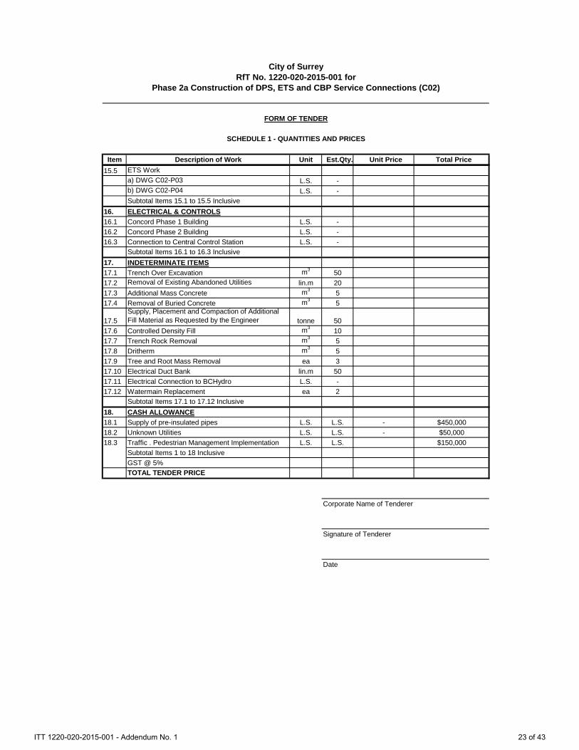
City of SurreyRfT No. 1220-020-2015-001 for
Phase 2a Construction of DPS, ETS and CBP Service Connections (C02)
FORM OF TENDER
SCHEDULE 1 - QUANTITIES AND PRICES
Item Description of Work Unit Est.Qty. Unit Price Total Price15.5 ETS Work
a) DWG C02-P03 L.S. -b) DWG C02-P04 L.S. -Subtotal Items 15.1 to 15.5 Inclusive
16. ELECTRICAL & CONTROLS16.1 Concord Phase 1 Building L.S. -16.2 Concord Phase 2 Building L.S. -16.3 Connection to Central Control Station L.S. -
Subtotal Items 16.1 to 16.3 Inclusive17. INDETERMINATE ITEMS17.1 Trench Over Excavation m3 5017.2 Removal of Existing Abandoned Utilities lin.m 2017.3 Additional Mass Concrete m3 517.4 Removal of Buried Concrete m3 5
17.5Supply, Placement and Compaction of Additional Fill Material as Requested by the Engineer tonne 50
17.6 Controlled Density Fill m3 1017.7 Trench Rock Removal m3 517.8 Dritherm m3 517.9 Tree and Root Mass Removal ea 317.10 Electrical Duct Bank lin.m 5017.11 Electrical Connection to BCHydro L.S. -17.12 Watermain Replacement ea 2
Subtotal Items 17.1 to 17.12 Inclusive18. CASH ALLOWANCE18.1 Supply of pre-insulated pipes L.S. L.S. - $450,00018.2 Unknown Utilities L.S. L.S. - $50,00018.3 Traffic . Pedestrian Management Implementation L.S. L.S. $150,000
Subtotal Items 1 to 18 Inclusive GST @ 5%TOTAL TENDER PRICE
Corporate Name of Tenderer
Signature of Tenderer
Date
ITT 1220-020-2015-001 - Addendum No. 1 23 of 43

1.1 Description of Payment Items
.1 Work set out in the Schedule of Quantities and Prices shall include, but not be limited by, the following brief descriptions:
PART 1 - GENERAL
1.1 Bonding and Insurance
This item shall include all costs for bonding and insurance for the complete Contract.
Payment will be made at the lump sum price tendered in the Schedule of Quantities and Prices on the first progress payment subsequent to submission of documentation of Bonding and Insurance coverage.
The lump sum tender under this item shall not exceed 1% of the total tender price.
1.2 Mobilization and Demobilization
This item shall include all costs for mobilization and demobilization associated with the Contractor's equipment, site facilities, and services including temporary access road for the work.
Payment for mobilization and demobilization will be made at the lump sum price shown in the Tender Form. Fifty percent (50%) of the lump sum price will be paid on the first progress payment certificate due after the Contractor has established the operation and facilities specified, and received the Owner’s approval of the construction schedule. The remaining 50% will be paid upon completion of the contract, removal of equipment, and cleanup and site restoration of the work areas to the satisfaction of the Engineer. The lump sum bid under this item shall not exceed 3% of the total tender. 1.3 Project Management / Overhead & Markup
This item shall include all cost related to project management, coordination and the overhead and markup for the unit rates in all the subsequent sections.
This item shall also include all cost to prepare a Traffic and Pedestrian Management Plan that covers the length of the Place of the Work. The Plan must be approved by the City prior to commencement of the Work. Cost should account for possible Plan revisions as requested by the City prior to final approval. Cost for implementation shall be covered under Cash Allowance (Refer to Section 18.3)
Payment will be made at the lump sum price quoted in the Schedule of Quantities and Prices.
ITT 1220-020-2015-001 - Addendum No. 1 24 of 43

1.4 Survey and Record Drawings This item shall include all costs for labour, materials and equipment to conduct:
1. Construction survey layout of all utilities to lines and grades as shown on drawings; and
2. Record survey of all as-built utility locations and elevations. Record survey information shall be provided to the Engineer in project datum in digital, CSV file (Northing, Easting, Elevation, Description) or AutoCAD DWG format. Information to include, but not limited to:
Manholes, Building Penetration (Location and Elevation) Centerline inverts of standard benched manholes Finished lid/rim centerline elevation D.E.S. Pipe (Location, Invert Elevation, Finished Surface Grade) All mainline fittings, bends, tees, valves, end caps, etc… All service line fittings, bends, tees, valves, end caps, etc… General (Location and Elevation) Existing utilities locations and inverts at D.E.S. Pipe crossings
Note: Construction Survey does not replace the requirement for the Contractor to maintain an accurate set of red-lined record drawings indicating all changes to the design.
This item shall also include all costs for labor and material to submit: 1. Operation & Maintenance Manuals 2. As-Built Drawings / Record Drawings 3. ISO’s / welding maps
Payment will be made at the lump sum price quoted in the Schedule of Quantities and Prices. PART 2 - SITE WORK
2.1 Site Preparation
This item shall include all costs for the completion of site work preparation for the D.E.S. piping installation. This shall include, but not be limited to, the clearing and grubbing of the site, removal of cleared and grubbed materials from site, and installation of temporary fencing. This shall also include asphalt and concrete saw cut as per the Drawings and Specifications. Payment will be made at the unit price tendered per lineal metre of prepared trench piping.
ITT 1220-020-2015-001 - Addendum No. 1 25 of 43

2.2 a),b),c),d) Trenching, Bedding & Import Backfill (1.2 – 1.8 m)
This item provides all compensation for all costs for excavation depth from 1.2 to 1.8 m of piping trenches, supply, place and compact bedding material and trench backfill. (For trenches to accommodate the D.E.S. Piping). The work includes but is not limited to:
• Trench excavation • Disposal of excavated material • Supply, placement, and compaction of bedding material in the pipe zone • Approved trench backfill • Excavation for tee installation • Shoring and dewatering • Testing of bedding and backfill material • Support of existing structures and piping
Payment will be made at the unit rate tendered for each lineal metre of piping trench. 2.3 a),b),c),d) Trenching, Bedding & Import Backfill (1.8 – 2.4 m) This item provides all compensation for all costs for excavation depth from 1.8 to 2.4 m of piping trenches, supply, place and compact bedding material and trench backfill. (For trenches to accommodate the D.E.S. Piping). The work includes but is not limited to:
• Trench excavation • Disposal of excavated material • Supply, placement, and compaction of bedding material in the pipe zone • Approved trench backfill up to subgrade • Excavation for tee installation • Shoring and dewatering • Testing of bedding and backfill material • Support of existing structures and piping
Payment will be made at the unit rate tendered for each lineal metre of piping trench.
ITT 1220-020-2015-001 - Addendum No. 1 26 of 43

2.4 a),b),c),d) Site Restoration This item shall include all costs for re-instatement of existing sod, seed, topsoil, turf, asphalt, sidewalks and curb and gutters, in areas disturbed by construction to City of Surrey standards. This item shall also include all costs for sawcut removal of concrete and asphalt, replacement of base and subbase materials as detailed on the construction drawings, line painting if applicable and sidewalk and curb restoration. All waste debris shall be disposed of off-site. Restoration work covered under this item is limited to that which is a direct result of construction activities in the immediate vicinity of the proposed works. Any other area appurtenances, surface features, etc. that have been disturbed by the Contractor shall be restored to their original condition at the cost of the Contractor. Payment will be made at the unit rate tendered in the Schedule of Quantities and Prices. 2.5 D.E.S. Manhole This item provides compensation for all costs for supply, construction, and installation of floating concrete manholes as shown on the drawings. Payment will be made at the unit rate tendered in the Schedule of Quantities and Prices. 2.6 Utilities Crossing This item provides compensation for all costs for supply, preparation, and installation of Styrofoam and insulation providing minimum clearance between existing utilities or bedrock and the D.E.S. piping. Payment will be made at the unit rates tendered for each crossing requiring minimum clearance. 2.7 D.E.S. Valve Boxes This item provides compensation for all costs for supply, construction, and installation of Valve Boxes as shown on the drawings. Payment will be made at the unit rate tendered in the Schedule of Quantities and Prices.
2.8 Air Release Valve Assembly
This item provides compensation for all costs for material and labour to supply and install air release valve manhole assembly including but not limited to precast manhole sections, lid, frame and cover, concrete blocks, and drain rock. The cost for valves, pipe tapping and related mechanical work shall be included in Part 15.
ITT 1220-020-2015-001 - Addendum No. 1 27 of 43

Payment will be made at the unit rate tendered for each air valve assembly installed. 2.9 100-mm-diameter Sewer
This item provides compensation for all costs for material and labour to supply and install 100-mm-diameter PVC sanitary sewer service as shown on the drawings and specifications, including but not limited to piping, fittings, couplings, equipment, cleanouts, inspection chambers, and all other additional work related to sanitary sewers and services.
Payment will be made at the unit rate tendered for each lineal metre of piping installed. 2.10 25-mm-diameter Water Service
This item provides compensation for all costs for material and labour to supply and install 25-mm-diameter water service as shown on the drawings and specifications, including but not limited to piping, valves, fittings, couplings, equipment, curb stop, connections to municipal utility and boiler plant, all other additional work related to water services.
Payment will be made at the unit rate tendered for each lineal metre of piping installed.
2.11 CBP Concrete Pad and connections (Optional)
This item provides compensation for all costs for material and labour to supply and install the Containerized Boiler Plant concrete pad as shown in the drawings including all necessary earth works and service connections not covered above. Payment will be made at of the lump sum price tendered in the Schedule of Quantities and Prices.
2.12 Fencing & Gate
This item provides compensation for all costs for material and labour to supply and install the fencing and gate as shown in the drawings.
2.13 Logstor Material Handling
This item provides compensation for all costs for material and labour to coordinate, receive, inspect, handle and track all Logstor® material as stated in the Schedule of Quantities in Section 01220 Part 2
Payment will be made at of the lump sum price tendered in the Schedule of Quantities and Prices. 2.14 FortisBC Gas Pad
This item provides compensation for all costs for material and labour to supply and install the FortisBC gas meter concrete pad as shown in the drawings.
ITT 1220-020-2015-001 - Addendum No. 1 28 of 43

Payment will be made at of the lump sum price tendered in the Schedule of Quantities and Prices. 2.15 DPS Control Conduit
This item provides compensation for all costs for material and labour to supply and install the DPS controls conduit and associated pull boxes as per the project drawings and specifications.
Payment will be made at of the lump sum price tendered in the Schedule of Quantities and Prices.
2.15 Miscellaneous Civil Works
This item provides compensation for all costs for material and labour to complete the following tasks a) Major Storm Main Crossing at 100th Ave (stabilize existing) b) Tree Relocation c) High Fines Surfacing Aggregate (100mm depth) d) Base (100mm depth) e) Sub-base (300mm depth) f) Subgrade fill (75mm minus gravel) g) Topsoil stripping at TEC (assumed 300mm depth with stockpiling and later
respreading) h) Asphalt driveway (75mm depth) i) TEC Landscaping (grass seeding)
Payment will be made at of the lump sum price tendered in the Schedule of Quantities and Prices. PART 15 - MECHANICAL
15.1 a),b),c),d) D.E.S. Piping and Valve System
This item provides compensation for all costs for mechanical works required in accordance with the drawings and specifications. This item shall include, but not be limited to, supply, preparation, and installation of D.E.S. piping, valves, equipment, pipe supports, fittings, couplings, poly wrapping and all other additional work related to D.E.S. piping equipment. This item shall also include all x-ray testing of every D.E.S. piping weld.
Payment will be made at the lump sum price quoted in the Schedule of Quantities and Prices.
ITT 1220-020-2015-001 - Addendum No. 1 29 of 43

15.2 Connections to Containerized Boiler Plant This item provides compensation for all costs for materials and labour for all connections to the Containerized Boiler Plant as shown on the drawings including but not limited to D.E.S. piping, water service and sanitary services.
Payment will be made at the lump sum price quoted in the Schedule of Quantities and Prices.
15.3 Testing & Commissioning of D.E.S. This item provides compensation for all costs required to flush, test, and commission all D.E.S. piping system installed as per the Drawings and Specifications.
Payment will be made at of the lump sum price tendered in the Schedule of Quantities and Prices. 15.4 Leak Detection This item provides compensation for all costs required for leak detection of the entire D.E.S. piping system installed. This will include the installation and wiring of the X1L in the Containerized Boiler Plant and the 1517 boxes in the two Phase 2a ETS only.
Payment will be made at of the lump sum price tendered in the Schedule of Quantities and Prices.
15.5 a),b) ETS Work
This item provides compensation for all costs for mechanical works required in accordance with the drawings and specifications. This item shall include, but not be limited to, supply, preparation, and installation of piping, valves, equipment, pipe supports, fittings, couplings and all other additional work related to the ETS piping equipment. This item shall also include all x-ray testing and commissioning as per project specifications.
Payment will be made at the lump sum price quoted in the Schedule of Quantities and Prices.
ITT 1220-020-2015-001 - Addendum No. 1 30 of 43

PART 16 - ELECTRICAL & CONTROLS
16.1 Concord Phase 1 Building
This item provides compensation for all costs for electrical and controls works required in accordance with the drawings and specifications for Concord Phase 1 building. This item shall include, but not be limited to, supply and installation of all electrical and controls components and all other additional work to have a fully operational system as per the project specifications.
Payment will be made at the lump sum price quoted in the Schedule of Quantities and Prices. 16.2 Concord Phase 2 Building
This item provides compensation for all costs for electrical and controls works required in accordance with the drawings and specifications for Concord Phase 2 building. This item shall include, but not be limited to, supply and installation of all electrical and controls components iand all other additional work to have a fully operational system as per the project specifications.
Payment will be made at the lump sum price quoted in the Schedule of Quantities and Prices. 16.3 Central Control Station
This item provides compensation for all costs for electrical and controls works required in accordance with the drawings and specifications for connecting Concord Phase 1 and Phase 2 buildings to the existing central control panel at City Hall.
Payment will be made at the lump sum price quoted in the Schedule of Quantities and Prices. PART 17 - INDETERMINATE ITEMS
All indeterminate items and the quantities identified in Schedule A may increase, decrease or not be used at all. No payment will be made if the work is not undertaken.
ITT 1220-020-2015-001 - Addendum No. 1 31 of 43

17.1 Trench Over Excavation
This item provides compensation for all costs associated with vertical pipe trench over excavation in general as directed by the Engineer. The work includes but is not limited to:
• Trench over excavation • Disposal of over excavated material • Additional fill material • Shoring and Dewatering • Testing of additional fill material
Payment will be made at the unit rate tendered based on the fill volume determined in the field by the Engineer. 17.2 Removal of Existing Abandoned Utilities This item includes all costs for supply of all materials, equipment, labour, excavation and backfill to remove and dispose of existing abandoned utilities in conflict with the D.E.S. piping alignment as directed by the Engineer. This item shall also include the additional fill material to replace the abandoned utilities volume.
Payment will be made at the unit rate tendered for each lineal metre of abandoned pipe removed.
17.3 Additional Mass Concrete as Requested by the Engineer
This item shall include all costs for crude forming and placement of mass concrete as requested by the Engineer.
Payment will be made at the unit price quoted in the Schedule of Quantities and Prices for each cubic meter of concrete in place. Measurement will be based on truck volume as per dispatch slips certified by the Engineer.
17.4 Removal of Buried Concrete
This item shall include all costs for supply of all materials, equipment, and labour for removal of buried concrete in conflict with the D.E.S. piping trench as directed by the Engineer. This item shall include, but not limited to saw cut and removal of concrete, disposal off site, and backfill with import material.
Payment will be made at the unit price quoted in the Schedule of Quantities and Prices for each cubic meter of concrete removed. Measurement will be based on field measurement by the Engineer
17.5 Supply, Placement and Compaction of Additional Fill Material as Requested by the Engineer
ITT 1220-020-2015-001 - Addendum No. 1 32 of 43

This item shall include all costs for supply, placement, and compaction of additional 75 mm minus free draining structural backfill material as requested by the Engineer.
Payment will be made at the unit price quoted in the Schedule of Quantities and Prices.
17.6 Controlled Density Fill
This item shall include all costs for forming, placing, finishing and curing of additional concrete density fill as requested by the Engineer.
Payment will be made at the unit price quoted in the Schedule of Quantities and Prices for each cubic meter of concrete in place. Measurement will be based on truck volume as per dispatch slips certified by the Engineer. 17.7 Trench Rock Excavation
This item provides compensation for the addition-al cost of removing and disposing of trench rock over that of earth excavation. Trench rock excavation shall include the excavation and disposal of all material which in the opinion of the Engineer requires for its removal either drilling and blasting, wedging, sledging, or breaking with a power operated hand tool. Rock excavation does not include the excavation of soft or disintegrated rock which can be removed with a handpick or power-operated excavation machine. NO payment will be considered for trench rock encountered in subgrade fill sections. Rock excavation shall also include the removal and disposal of boulders exceeding one (1) cubic metre in volume if within a trench section, or if exceeding two (2) cubic metres if within a road subgrade section, which lie wholly within the excavation and in the opinion of the Engineer interfere with the work. If an outcropping of bedrock protrudes into the excavation and a portion less than one (1) cubic metre in volume is removed by blasting, payment will be made for a minimum of one (1) cubic metre. Excavated rock shall be disposed of on-site at locations designated by the Engineer. Payment will be made for the volume of rock excavation at the unit rate tendered per cubic metre.
17.8 Dritherm
This item shall include all costs for supply, formwork, and placement of Dritherm material as requested by the Engineer.
ITT 1220-020-2015-001 - Addendum No. 1 33 of 43

Payment will be made at the unit price quoted in the Schedule of Quantities and Prices for each cubic meter of dritherm placed. Measurement will be based on field measurement by the Engineer.
17.9 Tree and Root Mass Removal
This item provides compensation for all costs for material and labour to remove tree and root mass from the pipe trench where in conflict with the D.E.S. piping where indicated on the drawings and where instructed by the Engineer.
Payment will be made at the unit rate tendered for each tree and root mass removed.
17.10 Electrical Duct Bank
This item provides compensation for all costs for material and labour to supply and install an underground electrical duct bank to connect the BCHydro transformer to the CBP as per this sketch:
17.11 Electrical Connection to BCHydro
This item provides compensation for all costs for material and labour to supply and install the electrical cable connecting the BCHydro transformer to the CBP. The scope of work shall allow for:
1. 60 m of cable (600V / 180 amps)
2. Cable termination
3. Coordination with C01 Contractor and BCHydro
4. Supply and installation of the main breaker and meter base enclosure mounted outside the CBP
ITT 1220-020-2015-001 - Addendum No. 1 34 of 43

2.7 Watermain Replacement
This item provides compensation for all costs for the relocation of a 300 mm existing watermain, to City of Surrey Standards, in direct conflict with the D.E.S. piping alignment.
Payment will be made at the unit rate tendered in Schedule 1 for each relocation as directed by the Engineer.
PART 18 - CASH ALLOWANCE
Refer to Division 00 for terms and conditions 18.3 Traffic & Pedestrian Management
This item also includes all costs for labour and equipment to implement the Traffic and Pedestrian Management Plan for the duration of the Work for all areas that it applies to. This includes coordination with, and notification to all applicable parties for lane or road closures. Payment will be made as required back up by time sheets and other supporting documentation.
END OF SECTION
ITT 1220-020-2015-001 - Addendum No. 1 35 of 43

Table of Contents No. Clause Page
PART 1 HEAT EXCHANGER QUANTITIES .................................................................. 2
PART 2 DISTRIBUTION PIPING SYSTEM QUANTITIES .............................................. 1
PART 3 INSTRUMENTATION AND CONTROLS QUANTITIES ................................... 3
ITT 1220-020-2015-001 - Addendum No. 1 36 of 43

PART 1 HEAT EXCHANGER QUANTITIES Refer to Table 1 for heat exchanger quantities; selections in the table take precedence over the values shown on the P&ID.
ITT 1220-020-2015-001 - Addendum No. 1 37 of 43
ITT 1220-020-2015-001 - Addendum No. 1 38 of 43

PART 2 DISTRIBUTION PIPING SYSTEM QUANTITIES Refer to Table 2 for distribution piping system material quantities.
ITT 1220-020-2015-001 - Addendum No. 1 39 of 43
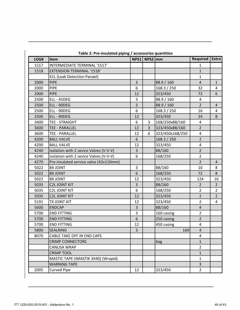
LOG# Item NPS1 NPS2 mm Required Extra1517 INTERMEDIATE TERMINAL '1517' 11518 EXTENSION TERMINAL '1518' 1
X1L (Leak Detection Panael) 12000 PIPE 3 88.9 / 160 4 12000 PIPE 6 168.3 / 250 32 42000 PIPE 12 323/450 72 62500 ELL - 45DEG 3 88.9 / 160 42500 ELL - 90DEG 3 88.9 / 160 2 42500 ELL - 90DEG 6 168.3 / 250 16 42500 ELL - 90DEG 12 323/450 24 83400 TEE - STRAIGHT 6 3 168/250x88/160 43600 TEE - PARALLEL 12 3 323/450x88/160 23600 TEE - PARALLEL 12 6 323/450x168/250 44200 BALL VALVE 6 168.3 / 250 24200 BALL VALVE 12 323/450 44240 Isolation with 2 sevice Valves (V-V-V) 3 88/160 24240 Isolation with 2 sevice Valves (V-V-V) 6 168/250 24270 Pre-insulated service valve (42x110mm) 2 45022 BX JOINT 3 88/160 10 85022 BX JOINT 6 168/250 72 85022 BX JOINT 12 323/450 124 165035 C2L JOINT KIT 3 88/160 2 25035 C2L JOINT KIT 6 168/250 2 25035 C2L JOINT KIT 12 323/450 2 25191 TX JOINT KIT 12 323/450 2 45600 ENDCAP 3 88/160 45700 END FITTING 3 160 casing 25700 END FITTING 6 250 casing 25700 END FITTING 12 450 casing 45800 SEALRING 3 160 48070 CABLE TAKE OFF IN END CAPS 4
CRIMP CONNECTORS bag 1CANUSA WRAP 2CRIMP TOOL 1MASTIC TAPE (IMASTIK 3X40) (Wrapid) 1WARNING TAPE 3
2005 Curved Pipe 12 323/450 2
Table 2: Pre-insulated piping / accessories quantities
ITT 1220-020-2015-001 - Addendum No. 1 40 of 43
PART 3 INSTRUMENTATION AND CONTROLS QUANTITIES Refer to Table 3 for controls and instrumentation quantities.
ITT 1220-020-2015-001 - Addendum No. 1 41 of 43

Table 3: Contractor Supplied Equipment - Control Schedule - Contract C02
C02-P03 Flow Control Valve 45.1-FCV-01 50 4.4 L/s ΔP Calculated: 21.2 kPa; Cv 40; Fail LastC02-P03 Flow Control Valve 45.1-FCV-02 63 8.4 L/s ΔP Calculated: 30.9 kPa; Cv 63; Fail closedC02-P03 Flow Meter & Transmitter 45.1-FE-01 50 10.7 L/sC02-P03 Temperature Element 45.1-TE-01 (1)C02-P03 Temperature Element 45.1-TE-02 (1)C02-P03 Temperature Element 45.1-TE-21 (2)C02-P03 Temperature Element 45.1-TE-22 (2)C02-P03 Temperature Element 45.1-TE-51 (2)C02-P03 Temperature Element 45.1-TE-52 (2)C02-P03 Pressure Transmitter 45.1-PT-01C02-P03 Pressure Transmitter 45.1-PT-02C02-P03 Energy Meter 45.1-JQ-01C02-P03 Local Panel LP
C02-P04 Flow Control Valve 45.2-FCV-01 50 6.3 L/s ΔP Calculated: 33.9 kPa; Cv 40; Fail LastC02-P04 Flow Control Valve 45.2-FCV-02 63 8.4 L/s ΔP Calculated: 30.9 kPa; Cv 63; Fail closedC02-P04 Flow Meter & Transmitter 45.2-FE-01 50 12.5 L/sC02-P04 Temperature Element 45.2-TE-01 (1)C02-P04 Temperature Element 45.2-TE-02 (1)C02-P04 Temperature Element 45.2-TE-21 (2)C02-P04 Temperature Element 45.2-TE-22 (2)C02-P04 Temperature Element 45.2-TE-51 (2)C02-P04 Temperature Element 45.2-TE-52 (2)C02-P04 Pressure Transmitter 45.2-PT-01C02-P04 Pressure Transmitter 45.2-PT-02C02-P04 Energy Meter 45.2-JQ-01C02-P04 Local Panel LP
Specific Notes: (1) temperature elements for energy metering must be paired, as per EN1434. (2) temperature elements installed on secondary lines.
Building Name
#45.1ConcordPhase 1
P&ID Drawing #
Tag #Equipment Size (mm)
#45.2ConcordPhase 2
Operating Setting Other / Comment Notes
General Notes: design temperature = 95°C and design pressure = 1,600 kPa (232 PSI)
ITT 1220-020-2015-001 - Addendum No. 1 42 of 43

END OF SECTION
ITT 1220-020-2015-001 - Addendum No. 1 43 of 43