INVITATION TO BID (SBD 1) on procurement requirements document... · Bid Number NRFNZG-013-2016/17...
205
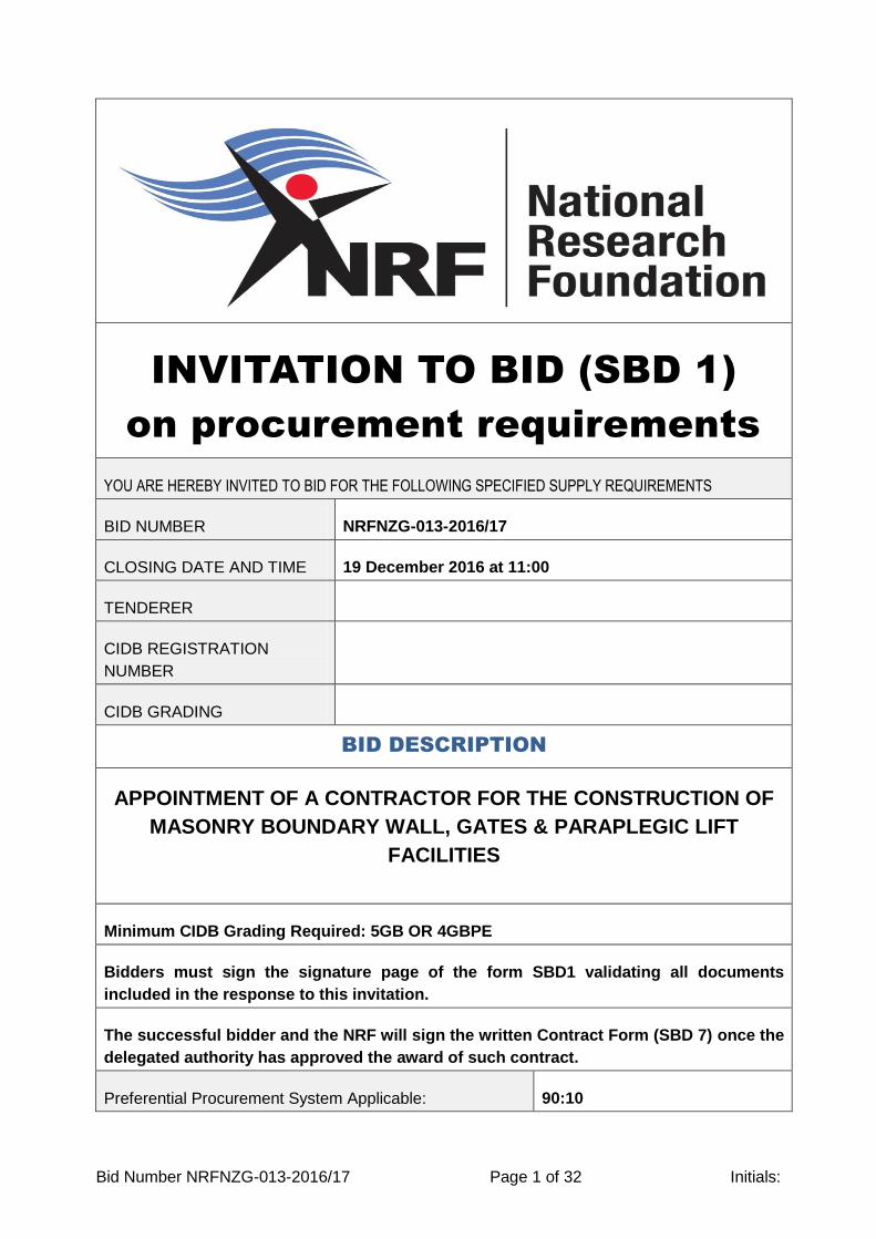
Bid Number NRFNZG-013-2016/17 Page 1 of 32 Initials: INVITATION TO BID (SBD 1) on procurement requirements YOU ARE HEREBY INVITED TO BID FOR THE FOLLOWING SPECIFIED SUPPLY REQUIREMENTS BID NUMBER NRFNZG-013-2016/17 CLOSING DATE AND TIME 19 December 2016 at 11:00 TENDERER CIDB REGISTRATION NUMBER CIDB GRADING BID DESCRIPTION APPOINTMENT OF A CONTRACTOR FOR THE CONSTRUCTION OF MASONRY BOUNDARY WALL, GATES & PARAPLEGIC LIFT FACILITIES Minimum CIDB Grading Required: 5GB OR 4GBPE Bidders must sign the signature page of the form SBD1 validating all documents included in the response to this invitation. The successful bidder and the NRF will sign the written Contract Form (SBD 7) once the delegated authority has approved the award of such contract. Preferential Procurement System Applicable: 90:10
Transcript of INVITATION TO BID (SBD 1) on procurement requirements document... · Bid Number NRFNZG-013-2016/17...
Bid Number NRFNZG-013-2016/17 Page 1 of 32 Initials:
INVITATION TO BID (SBD 1)
on procurement requirements
YOU ARE HEREBY INVITED TO BID FOR THE FOLLOWING SPECIFIED SUPPLY REQUIREMENTS
BID NUMBER NRFNZG-013-2016/17
CLOSING DATE AND TIME 19 December 2016 at 11:00
TENDERER
CIDB REGISTRATION
NUMBER
CIDB GRADING
BID DESCRIPTION
APPOINTMENT OF A CONTRACTOR FOR THE CONSTRUCTION OF
MASONRY BOUNDARY WALL, GATES & PARAPLEGIC LIFT
FACILITIES
Minimum CIDB Grading Required: 5GB OR 4GBPE
Bidders must sign the signature page of the form SBD1 validating all documents
included in the response to this invitation.
The successful bidder and the NRF will sign the written Contract Form (SBD 7) once the
delegated authority has approved the award of such contract.
Preferential Procurement System Applicable: 90:10
Bid Number NRFNZG-013-2016/17 Page 2 of 32 Initials:
Validity Period From Date Of Closure: 150 days
Compulsory
Briefing
Session or
Site Visit
Details
Date and Time 02 November 2016 at 11:00
Location NATIONAL ZOOLOGICAL GARDENS OF SOUTH
AFRICA, 232 BOOM STR. PRETORIA
Contact Person Chumisa Loyilane - 0123392700
BID DOCUMENTS ARE TO BE DEPOSITED IN THE BID BOX AT:
PHYSICAL ADDRESS:
NATIONAL ZOOLOGICAL
GARDENS OF SA
CORNER BOOM STREET AND
PAUL KGUGER
NO 232 BOOM STREET
PRETORIA
0001
AND ADDRESSED AS FOLLOWS:
On the face of each envelope, the Bid Number and
Bidder’s Name, Postal Address, Contact Name,
Telephone Number and email address
BIDDERS ARE REQUIRED TO DELIVER THEIR BID TO THE CORRECT ADDRESS
TIMEOUSLY IN ORDER FOR THE NRF TO CONSIDER IT. THE NRF WILL NOT
CONSIDER THE BIDS RECEIVED LATER THAN THE CLOSING DATE AND TIME NOR
RETURN THESE TO THE BIDDER.
Bidders must submit their bid response on the official bid invitation forms (not to be re-
typed) with additional information provided on attached supporting schedules.
The NRF provides the checklist “Returnable Documents” of all required
documentation with certain documentation mandatory for entering the evaluation
phase.
Non-submission of these marked documents will lead to disqualification of the
bidder.
THIS BID IS SUBJECT TO THE PREFERENTIAL PROCUREMENT POLICY
FRAMEWORK ACT AND THE PREFERENTIAL PROCUREMENT REGULATIONS - 2011.
THIS BID IS SUBJECT TO THE GENERAL CONDITIONS OF CONTRACT AND SPECIAL
CONDITIONS OF CONTRACT AS STIPULATED IN THIS INVITATION.
The NRF deems the bidder has read and accepted these conditions of contract.
REGISTRATION ON THE CENTRAL SUPPLIER DATABASE (CSD):
The bidder must register on the National Treasury’s Central Supplier Database in order to
do business with an organ of state or for the NRF to award a bid or contract. Registration

Bid Number NRFNZG-013-2016/17 Page 3 of 32 Initials:
on the CSD (www.csd.gov.za) provides a bidder with an opportunity to do business with all
state organisations including provincial and municipal levels.
National Treasury Contact Details: 012 406 9222 or email [email protected]
SETS OF BID DOCUMENTS REQUIRED:
Number of ORIGINAL documents for contract signing 2
Bidders must submit the bid in hard copy format (paper document) to the NRF. The hard
copy of these original sets of bid documents serve as the legal bid contract document and
the master record between the bidder and the NRF. The bidders attach the originals or
certified copies of any certificates stipulated in this document to these original sets of bid
documents.
Any discrepancy between the evaluation copies and the master record, the master record
will prevail. Any discrepancy between the original sets deposited with the NRF and that
kept by the bidder, the original set deposited with the NRF is the master contract for both
parties.
Two envelope system required YES
The objective of the exercise is to evaluate the Proposals Section without reference to the
Price Section ensuring both sections are evaluated fairly and unbiased.
The first envelope holds all documents excluding the SBD3 and detailed supporting pricing
documentation. The second envelope holds the SBD3 and the detailed supporting pricing
documentation. An outer envelope encloses both envelopes that have the envelope
addressing as stated in this document.
The NRF only opens the proposal – the first envelope – at the evaluation stage and only
opens the pricing – the second envelope – for those bidders who meet the predefined
threshold at the proposal evaluation.
ENQUIRIES CAN BE DIRECTED TO THE FOLLOWING
TECHNICAL ENQUIRIES SUPPLY CHAIN MANAGEMENT ENQUIRIES
Ms Chumisa Loyilane
012 339 2710
Ms Monica Thapeli
012 339 2746
TABLE OF CONTENTS
Bid Number NRFNZG-013-2016/17 Page 4 of 32 Initials:
BID DESCRIPTION .............................................................................................................. 1
SETS OF BID DOCUMENTS REQUIRED: ........................................................................... 3
ENQUIRIES CAN BE DIRECTED TO THE FOLLOWING .................................................... 3
RETURNABLE DOCUMENT CHECKLIST TO QUALIFY FOR EVALUATION ..................... 5
THE BIDDING PROCESS .................................................................................................... 6
EVALUATION CRITERIA FOR EVALUATING BIDDERS RESPONSES .............................. 8
THRESHOLD TO QUALIFY FOR PRICE/PREFERENCE EVALUATION STAGE 3 ........... 10
THE BIDDERS PARTICULARS.......................................................................................... 10
INTRODUCTION TO THE NRF .......................................................................................... 12
INTRODUCTION TO THE NRF BUSINESS UNIT RESPONSIBLE FOR THIS BID ............ 13
CONTEXT .......................................................................................................................... 13
CONTRACT PERIOD ......................................................................................................... 14
SPECIFICATIONS FOR THE REQUIRED PROCUREMENT ............................................. 15
PRICING DETAIL .............................................................. Error! Bookmark not defined.16
PREFERENCE POINTS CLAIMED (SBD 6.1) .................................................................... 17
DUE DILIGENCE REQUIREMENTS .................................................................................. 21
OBLIGATIONS OF EACH PARTY ...................................................................................... 25
GENERAL CONDITIONS OF CONTRACT ........................................................................ 28
NATIONAL RESEARCH FOUNDATION ANNEXURES ..................................................... 28
BID SUBMISSION CERTIFICATE FORM - (SBD 1) ........................................................... 30
Bid Number NRFNZG-013-2016/17 Page 5 of 32 Initials:
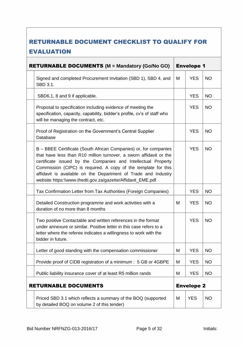
RETURNABLE DOCUMENT CHECKLIST TO QUALIFY FOR
EVALUATION
RETURNABLE DOCUMENTS (M = Mandatory (Go/No GO) Envelope 1
Signed and completed Procurement Invitation (SBD 1), SBD 4, and
SBD 3.1.
M YES NO
SBD6.1, 8 and 9 if applicable. YES NO
Proposal to specification including evidence of meeting the
specification, capacity, capability, bidder’s profile, cv’s of staff who
will be managing the contract, etc.
YES NO
Proof of Registration on the Government’s Central Supplier
Database
YES NO
B – BBEE Certificate (South African Companies) or, for companies
that have less than R10 million turnover, a sworn affidavit or the
certificate issued by the Companies and Intellectual Property
Commission (CIPC) is required. A copy of the template for this
affidavit is available on the Department of Trade and Industry
website https:\\www.thedti.gov.za/gazette/Affidavit_EME.pdf
YES NO
Tax Confirmation Letter from Tax Authorities (Foreign Companies) YES NO
Detailed Construction programme and work activities with a
duration of no more than 8 months
M YES NO
Two positive Contactable and written references in the format
under annexure or similar. Positive letter in this case refers to a
letter where the referee indicates a willingness to work with the
bidder in future.
YES NO
Letter of good standing with the compensation commissioner M YES NO
Provide proof of CIDB registration of a minimum : 5 GB or 4GBPE M YES NO
Public liability insurance cover of at least R5 million rands M YES NO
RETURNABLE DOCUMENTS Envelope 2
Priced SBD 3.1 which reflects a summary of the BOQ (supported
by detailed BOQ on volume 2 of this tender)
M YES NO
Bid Number NRFNZG-013-2016/17 Page 6 of 32 Initials:
Priced Bill of Quantity M YES NO
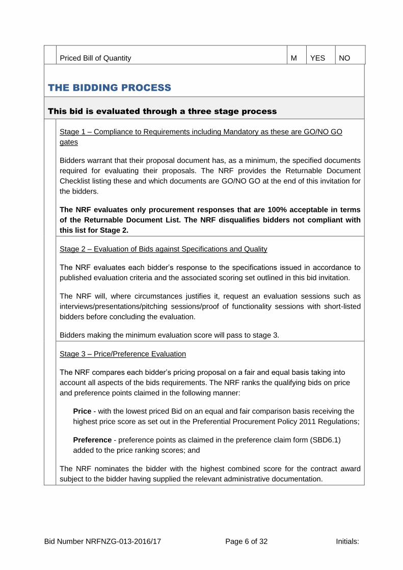
THE BIDDING PROCESS
This bid is evaluated through a three stage process
Stage 1 – Compliance to Requirements including Mandatory as these are GO/NO GO
gates
Bidders warrant that their proposal document has, as a minimum, the specified documents
required for evaluating their proposals. The NRF provides the Returnable Document
Checklist listing these and which documents are GO/NO GO at the end of this invitation for
the bidders.
The NRF evaluates only procurement responses that are 100% acceptable in terms
of the Returnable Document List. The NRF disqualifies bidders not compliant with
this list for Stage 2.
Stage 2 – Evaluation of Bids against Specifications and Quality
The NRF evaluates each bidder’s response to the specifications issued in accordance to
published evaluation criteria and the associated scoring set outlined in this bid invitation.
The NRF will, where circumstances justifies it, request an evaluation sessions such as
interviews/presentations/pitching sessions/proof of functionality sessions with short-listed
bidders before concluding the evaluation.
Bidders making the minimum evaluation score will pass to stage 3.
Stage 3 – Price/Preference Evaluation
The NRF compares each bidder’s pricing proposal on a fair and equal basis taking into
account all aspects of the bids requirements. The NRF ranks the qualifying bids on price
and preference points claimed in the following manner:
Price - with the lowest priced Bid on an equal and fair comparison basis receiving the
highest price score as set out in the Preferential Procurement Policy 2011 Regulations;
Preference - preference points as claimed in the preference claim form (SBD6.1)
added to the price ranking scores; and
The NRF nominates the bidder with the highest combined score for the contract award
subject to the bidder having supplied the relevant administrative documentation.
Bid Number NRFNZG-013-2016/17 Page 7 of 32 Initials:
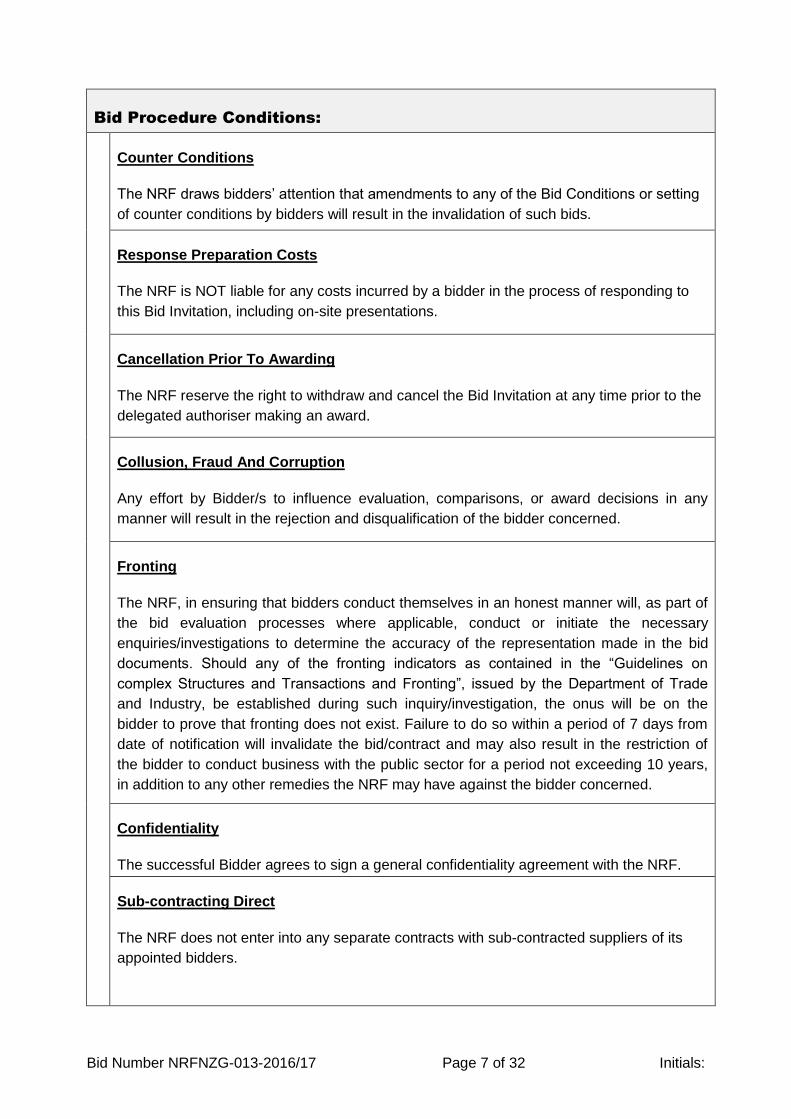
Bid Procedure Conditions:
Counter Conditions
The NRF draws bidders’ attention that amendments to any of the Bid Conditions or setting
of counter conditions by bidders will result in the invalidation of such bids.
Response Preparation Costs
The NRF is NOT liable for any costs incurred by a bidder in the process of responding to
this Bid Invitation, including on-site presentations.
Cancellation Prior To Awarding
The NRF reserve the right to withdraw and cancel the Bid Invitation at any time prior to the
delegated authoriser making an award.
Collusion, Fraud And Corruption
Any effort by Bidder/s to influence evaluation, comparisons, or award decisions in any
manner will result in the rejection and disqualification of the bidder concerned.
Fronting
The NRF, in ensuring that bidders conduct themselves in an honest manner will, as part of
the bid evaluation processes where applicable, conduct or initiate the necessary
enquiries/investigations to determine the accuracy of the representation made in the bid
documents. Should any of the fronting indicators as contained in the “Guidelines on
complex Structures and Transactions and Fronting”, issued by the Department of Trade
and Industry, be established during such inquiry/investigation, the onus will be on the
bidder to prove that fronting does not exist. Failure to do so within a period of 7 days from
date of notification will invalidate the bid/contract and may also result in the restriction of
the bidder to conduct business with the public sector for a period not exceeding 10 years,
in addition to any other remedies the NRF may have against the bidder concerned.
Confidentiality
The successful Bidder agrees to sign a general confidentiality agreement with the NRF.
Sub-contracting Direct
The NRF does not enter into any separate contracts with sub-contracted suppliers of its
appointed bidders.
Bid Number NRFNZG-013-2016/17 Page 8 of 32 Initials:
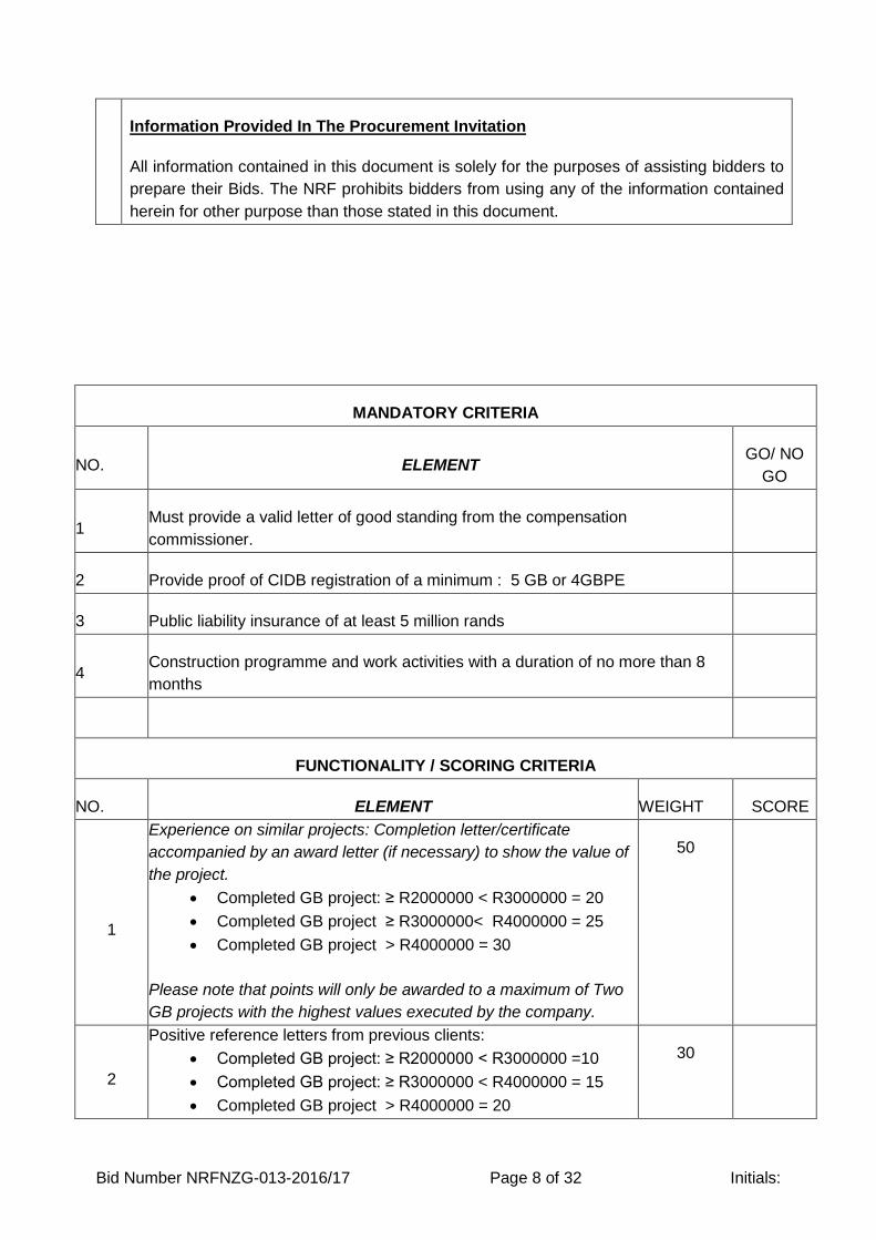
Information Provided In The Procurement Invitation
All information contained in this document is solely for the purposes of assisting bidders to
prepare their Bids. The NRF prohibits bidders from using any of the information contained
herein for other purpose than those stated in this document.
MANDATORY CRITERIA
NO. ELEMENT GO/ NO
GO
1 Must provide a valid letter of good standing from the compensation
commissioner.
2 Provide proof of CIDB registration of a minimum : 5 GB or 4GBPE
3 Public liability insurance of at least 5 million rands
4 Construction programme and work activities with a duration of no more than 8
months
FUNCTIONALITY / SCORING CRITERIA
NO. ELEMENT WEIGHT SCORE
1
Experience on similar projects: Completion letter/certificate
accompanied by an award letter (if necessary) to show the value of
the project.
Completed GB project: ≥ R2000000 < R3000000 = 20
Completed GB project ≥ R3000000< R4000000 = 25
Completed GB project > R4000000 = 30
Please note that points will only be awarded to a maximum of Two
GB projects with the highest values executed by the company.
50
2
Positive reference letters from previous clients:
Completed GB project: ≥ R2000000 < R3000000 =10
Completed GB project: ≥ R3000000 < R4000000 = 15
Completed GB project > R4000000 = 20
30

Bid Number NRFNZG-013-2016/17 Page 9 of 32 Initials:
Please note that points will only be awarded to a maximum of Two
positive reference letters from GB projects with the highest values.
Positive letter in this case refers to a letter where the referee
indicates a willingness to work with the bidder in future.
3
Construction related Qualifications and Experience of the Director/s
of the company:
National Diploma/Degree or Higher = 10 (Attach certificate as proof)
National N Diploma/N6 or equivalent = 5
Min 5 years construction experience = 10 (Attach CV as proof)
Min 3 years construction experience = 5
20
Minimum Threshold for functionality is at least 70 points
Bid Number NRFNZG-013-2016/17 Page 10 of 32 Initials:
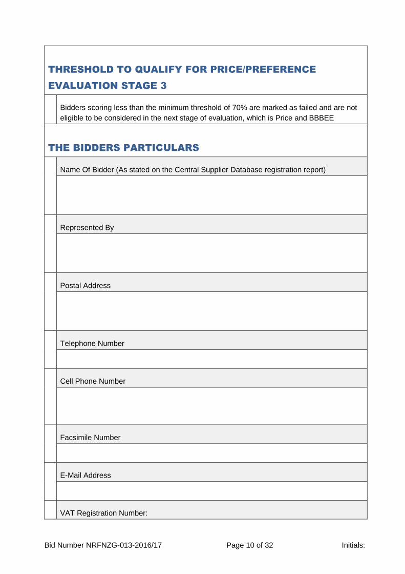
THRESHOLD TO QUALIFY FOR PRICE/PREFERENCE
EVALUATION STAGE 3
Bidders scoring less than the minimum threshold of 70% are marked as failed and are not
eligible to be considered in the next stage of evaluation, which is Price and BBBEE
THE BIDDERS PARTICULARS
Name Of Bidder (As stated on the Central Supplier Database registration report)
Represented By
Postal Address
Telephone Number
Cell Phone Number
Facsimile Number
E-Mail Address
VAT Registration Number:
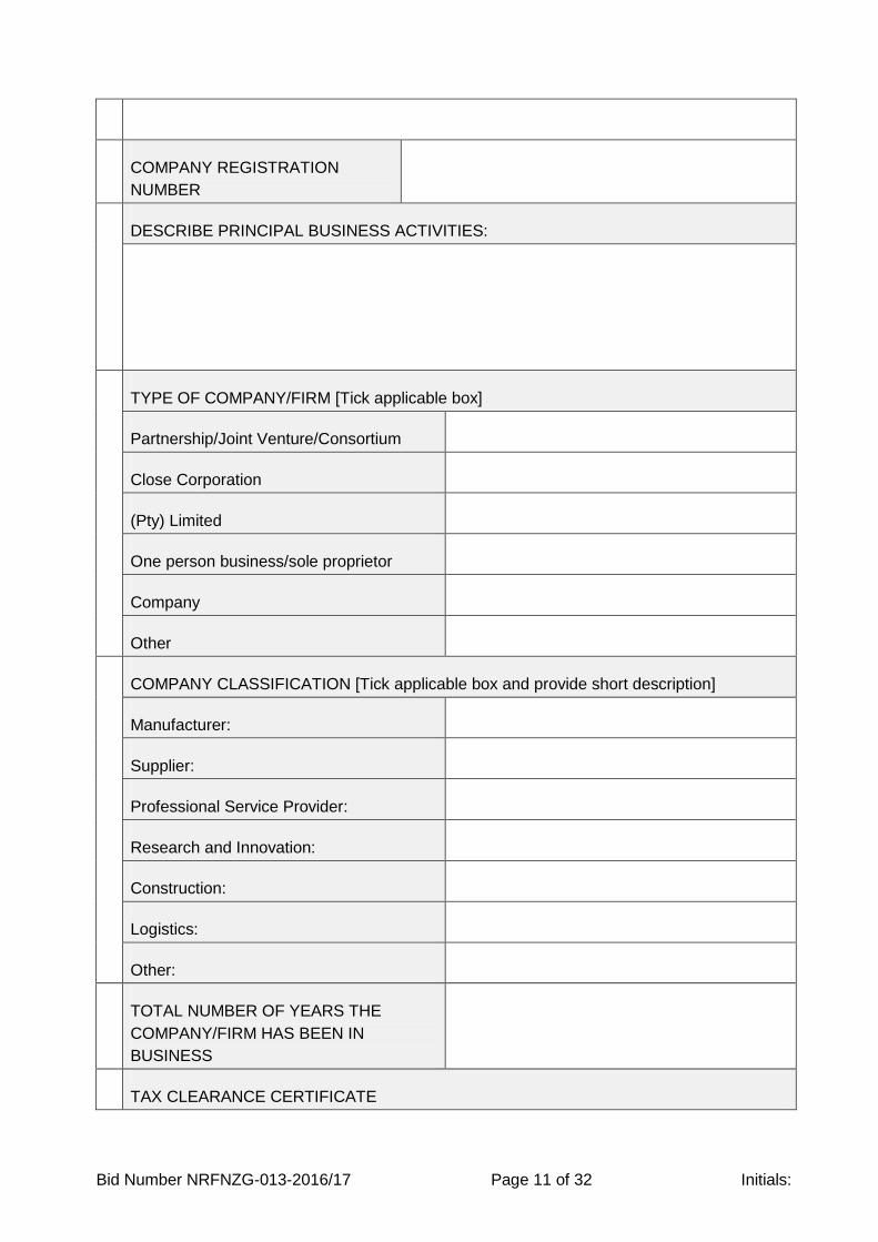
Bid Number NRFNZG-013-2016/17 Page 11 of 32 Initials:
COMPANY REGISTRATION
NUMBER
DESCRIBE PRINCIPAL BUSINESS ACTIVITIES:
TYPE OF COMPANY/FIRM [Tick applicable box]
Partnership/Joint Venture/Consortium
Close Corporation
(Pty) Limited
One person business/sole proprietor
Company
Other
COMPANY CLASSIFICATION [Tick applicable box and provide short description]
Manufacturer:
Supplier:
Professional Service Provider:
Research and Innovation:
Construction:
Logistics:
Other:
TOTAL NUMBER OF YEARS THE
COMPANY/FIRM HAS BEEN IN
BUSINESS
TAX CLEARANCE CERTIFICATE
Bid Number NRFNZG-013-2016/17 Page 12 of 32 Initials:
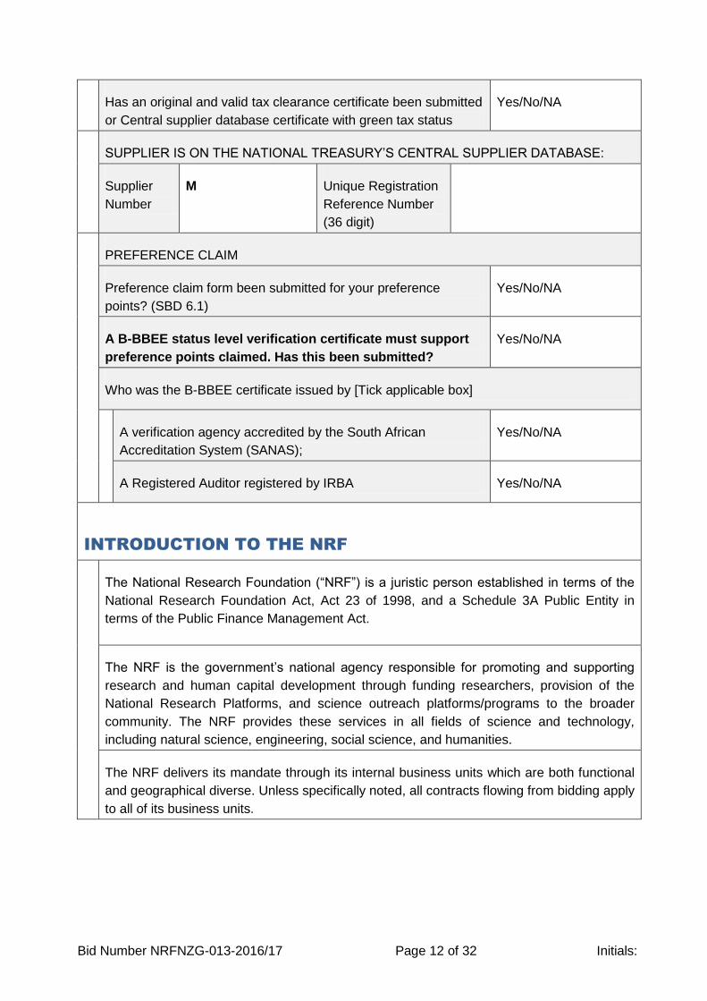
Has an original and valid tax clearance certificate been submitted
or Central supplier database certificate with green tax status
Yes/No/NA
SUPPLIER IS ON THE NATIONAL TREASURY’S CENTRAL SUPPLIER DATABASE:
Supplier
Number
M Unique Registration
Reference Number
(36 digit)
PREFERENCE CLAIM
Preference claim form been submitted for your preference
points? (SBD 6.1)
Yes/No/NA
A B-BBEE status level verification certificate must support
preference points claimed. Has this been submitted?
Yes/No/NA
Who was the B-BBEE certificate issued by [Tick applicable box]
A verification agency accredited by the South African
Accreditation System (SANAS);
Yes/No/NA
A Registered Auditor registered by IRBA Yes/No/NA
INTRODUCTION TO THE NRF
The National Research Foundation (“NRF”) is a juristic person established in terms of the
National Research Foundation Act, Act 23 of 1998, and a Schedule 3A Public Entity in
terms of the Public Finance Management Act.
The NRF is the government’s national agency responsible for promoting and supporting
research and human capital development through funding researchers, provision of the
National Research Platforms, and science outreach platforms/programs to the broader
community. The NRF provides these services in all fields of science and technology,
including natural science, engineering, social science, and humanities.
The NRF delivers its mandate through its internal business units which are both functional
and geographical diverse. Unless specifically noted, all contracts flowing from bidding apply
to all of its business units.
Bid Number NRFNZG-013-2016/17 Page 13 of 32 Initials:
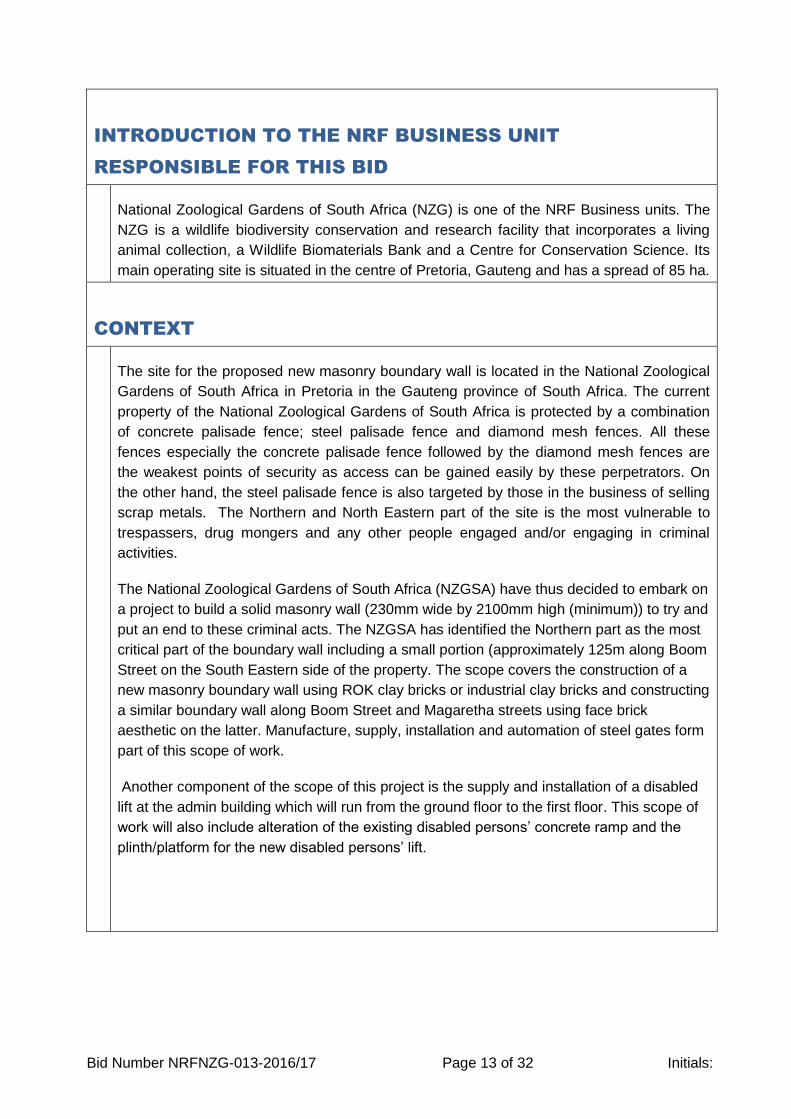
INTRODUCTION TO THE NRF BUSINESS UNIT
RESPONSIBLE FOR THIS BID
National Zoological Gardens of South Africa (NZG) is one of the NRF Business units. The
NZG is a wildlife biodiversity conservation and research facility that incorporates a living
animal collection, a Wildlife Biomaterials Bank and a Centre for Conservation Science. Its
main operating site is situated in the centre of Pretoria, Gauteng and has a spread of 85 ha.
CONTEXT
The site for the proposed new masonry boundary wall is located in the National Zoological
Gardens of South Africa in Pretoria in the Gauteng province of South Africa. The current
property of the National Zoological Gardens of South Africa is protected by a combination
of concrete palisade fence; steel palisade fence and diamond mesh fences. All these
fences especially the concrete palisade fence followed by the diamond mesh fences are
the weakest points of security as access can be gained easily by these perpetrators. On
the other hand, the steel palisade fence is also targeted by those in the business of selling
scrap metals. The Northern and North Eastern part of the site is the most vulnerable to
trespassers, drug mongers and any other people engaged and/or engaging in criminal
activities.
The National Zoological Gardens of South Africa (NZGSA) have thus decided to embark on
a project to build a solid masonry wall (230mm wide by 2100mm high (minimum)) to try and
put an end to these criminal acts. The NZGSA has identified the Northern part as the most
critical part of the boundary wall including a small portion (approximately 125m along Boom
Street on the South Eastern side of the property. The scope covers the construction of a
new masonry boundary wall using ROK clay bricks or industrial clay bricks and constructing
a similar boundary wall along Boom Street and Magaretha streets using face brick
aesthetic on the latter. Manufacture, supply, installation and automation of steel gates form
part of this scope of work.
Another component of the scope of this project is the supply and installation of a disabled
lift at the admin building which will run from the ground floor to the first floor. This scope of
work will also include alteration of the existing disabled persons’ concrete ramp and the
plinth/platform for the new disabled persons’ lift.

Bid Number NRFNZG-013-2016/17 Page 14 of 32 Initials:
CONTRACT PERIOD
The contract period will be based on the accepted programme of works from the contractor
but shall not exceed 8 months as stipulated above. The contract period commences from
the date that both parties sign the contract (SBD7)

Bid Number NRFNZG-013-2016/17 Page 15 of 32 Initials:
SPECIFICATIONS FOR THE REQUIRED PROCUREMENT
WORKS REQUIRED (delete if not applicable)
Refer to the Technical drawings together with the Bill of quantities (BoQ) and Project
specifications on volume 2 and 3 respectively.
Bid Number NRFNZG-013-2016/17 Page 16 of 32 Initials:
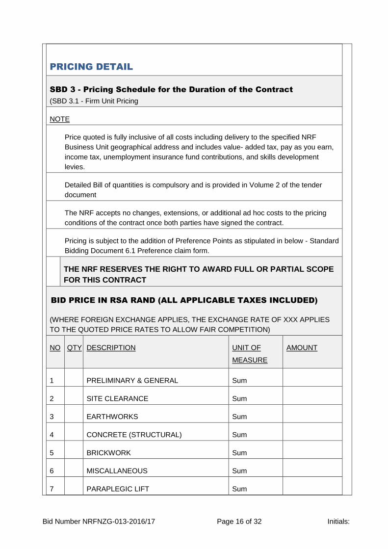
PRICING DETAIL
SBD 3 - Pricing Schedule for the Duration of the Contract
(SBD 3.1 - Firm Unit Pricing
NOTE
Price quoted is fully inclusive of all costs including delivery to the specified NRF
Business Unit geographical address and includes value- added tax, pay as you earn,
income tax, unemployment insurance fund contributions, and skills development
levies.
Detailed Bill of quantities is compulsory and is provided in Volume 2 of the tender
document
The NRF accepts no changes, extensions, or additional ad hoc costs to the pricing
conditions of the contract once both parties have signed the contract.
Pricing is subject to the addition of Preference Points as stipulated in below - Standard
Bidding Document 6.1 Preference claim form.
THE NRF RESERVES THE RIGHT TO AWARD FULL OR PARTIAL SCOPE
FOR THIS CONTRACT
BID PRICE IN RSA RAND (ALL APPLICABLE TAXES INCLUDED)
(WHERE FOREIGN EXCHANGE APPLIES, THE EXCHANGE RATE OF XXX APPLIES
TO THE QUOTED PRICE RATES TO ALLOW FAIR COMPETITION)
NO QTY DESCRIPTION UNIT OF
MEASURE
AMOUNT
1 PRELIMINARY & GENERAL Sum
2 SITE CLEARANCE Sum
3 EARTHWORKS Sum
4 CONCRETE (STRUCTURAL) Sum
5 BRICKWORK Sum
6 MISCALLANEOUS Sum
7 PARAPLEGIC LIFT Sum
Bid Number NRFNZG-013-2016/17 Page 17 of 32 Initials:
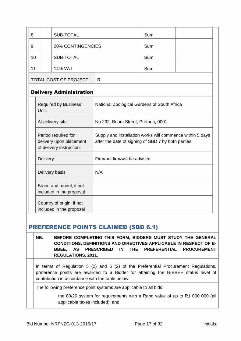
8 SUB-TOTAL Sum
9 20% CONTINGENCIES Sum
10 SUB-TOTAL Sum
11 14% VAT Sum
TOTAL COST OF PROJECT R
Delivery Administration
Required by Business
Unit:
National Zoological Gardens of South Africa
At delivery site: No 232, Boom Street, Pretoria, 0001
Period required for
delivery upon placement
of delivery instruction:
Supply and installation works will commence within 5 days
after the date of signing of SBD 7 by both parties.
Delivery Firm/not firm/will be advised
Delivery basis N/A
Brand and model, if not
included in the proposal
Country of origin, if not
included in the proposal
PREFERENCE POINTS CLAIMED (SBD 6.1)
NB: BEFORE COMPLETING THIS FORM, BIDDERS MUST STUDY THE GENERAL
CONDITIONS, DEFINITIONS AND DIRECTIVES APPLICABLE IN RESPECT OF B-
BBEE, AS PRESCRIBED IN THE PREFERENTIAL PROCUREMENT
REGULATIONS, 2011.
In terms of Regulation 5 (2) and 6 (2) of the Preferential Procurement Regulations,
preference points are awarded to a Bidder for attaining the B-BBEE status level of
contribution in accordance with the table below:
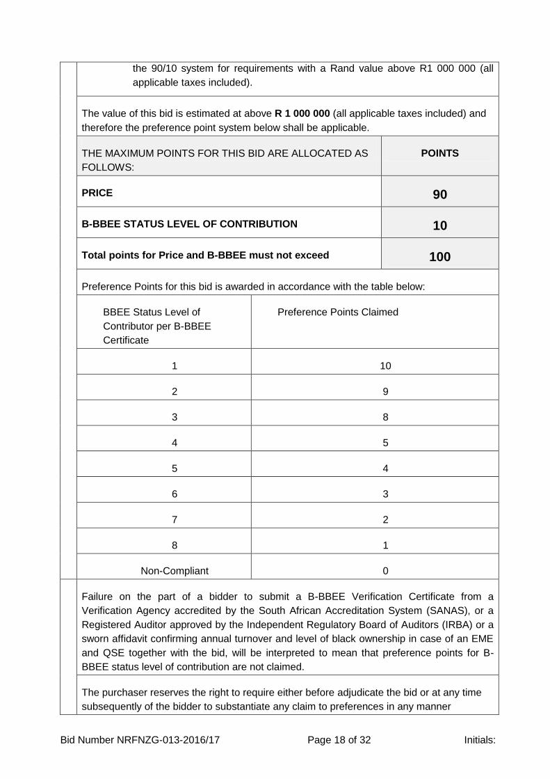
The following preference point systems are applicable to all bids:
- the 80/20 system for requirements with a Rand value of up to R1 000 000 (all
applicable taxes included); and
Bid Number NRFNZG-013-2016/17 Page 18 of 32 Initials:
- the 90/10 system for requirements with a Rand value above R1 000 000 (all
applicable taxes included).
The value of this bid is estimated at above R 1 000 000 (all applicable taxes included) and
therefore the preference point system below shall be applicable.
THE MAXIMUM POINTS FOR THIS BID ARE ALLOCATED AS
FOLLOWS:
POINTS
PRICE 90
B-BBEE STATUS LEVEL OF CONTRIBUTION 10
Total points for Price and B-BBEE must not exceed 100
Preference Points for this bid is awarded in accordance with the table below:
BBEE Status Level of
Contributor per B-BBEE
Certificate
Preference Points Claimed
1 10
2 9
3 8
4 5
5 4
6 3
7 2
8 1
Non-Compliant 0
Failure on the part of a bidder to submit a B-BBEE Verification Certificate from a
Verification Agency accredited by the South African Accreditation System (SANAS), or a
Registered Auditor approved by the Independent Regulatory Board of Auditors (IRBA) or a
sworn affidavit confirming annual turnover and level of black ownership in case of an EME
and QSE together with the bid, will be interpreted to mean that preference points for B-
BBEE status level of contribution are not claimed.
The purchaser reserves the right to require either before adjudicate the bid or at any time
subsequently of the bidder to substantiate any claim to preferences in any manner
Bid Number NRFNZG-013-2016/17 Page 19 of 32 Initials:
required.
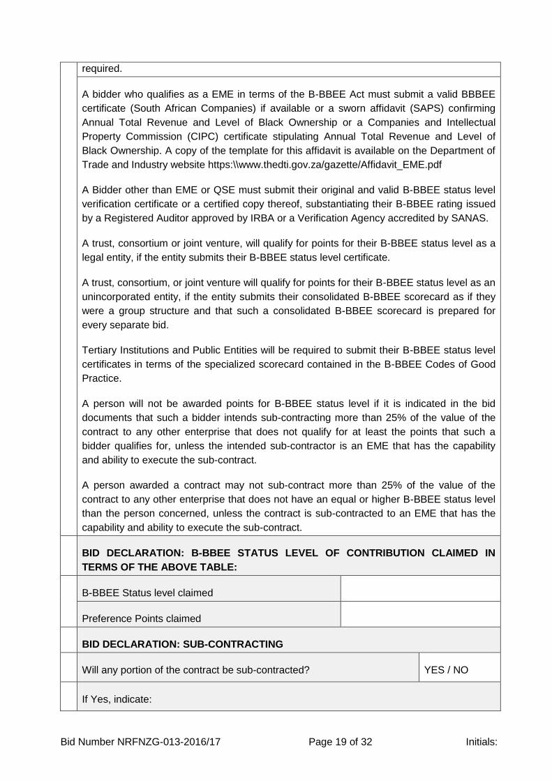
A bidder who qualifies as a EME in terms of the B-BBEE Act must submit a valid BBBEE
certificate (South African Companies) if available or a sworn affidavit (SAPS) confirming
Annual Total Revenue and Level of Black Ownership or a Companies and Intellectual
Property Commission (CIPC) certificate stipulating Annual Total Revenue and Level of
Black Ownership. A copy of the template for this affidavit is available on the Department of
Trade and Industry website https:\\www.thedti.gov.za/gazette/Affidavit_EME.pdf
A Bidder other than EME or QSE must submit their original and valid B-BBEE status level
verification certificate or a certified copy thereof, substantiating their B-BBEE rating issued
by a Registered Auditor approved by IRBA or a Verification Agency accredited by SANAS.
A trust, consortium or joint venture, will qualify for points for their B-BBEE status level as a
legal entity, if the entity submits their B-BBEE status level certificate.
A trust, consortium, or joint venture will qualify for points for their B-BBEE status level as an
unincorporated entity, if the entity submits their consolidated B-BBEE scorecard as if they
were a group structure and that such a consolidated B-BBEE scorecard is prepared for
every separate bid.
Tertiary Institutions and Public Entities will be required to submit their B-BBEE status level
certificates in terms of the specialized scorecard contained in the B-BBEE Codes of Good
Practice.
A person will not be awarded points for B-BBEE status level if it is indicated in the bid
documents that such a bidder intends sub-contracting more than 25% of the value of the
contract to any other enterprise that does not qualify for at least the points that such a
bidder qualifies for, unless the intended sub-contractor is an EME that has the capability
and ability to execute the sub-contract.
A person awarded a contract may not sub-contract more than 25% of the value of the
contract to any other enterprise that does not have an equal or higher B-BBEE status level
than the person concerned, unless the contract is sub-contracted to an EME that has the
capability and ability to execute the sub-contract.
BID DECLARATION: B-BBEE STATUS LEVEL OF CONTRIBUTION CLAIMED IN
TERMS OF THE ABOVE TABLE:
B-BBEE Status level claimed
Preference Points claimed
BID DECLARATION: SUB-CONTRACTING
Will any portion of the contract be sub-contracted? YES / NO
If Yes, indicate:
Bid Number NRFNZG-013-2016/17 Page 20 of 32 Initials:
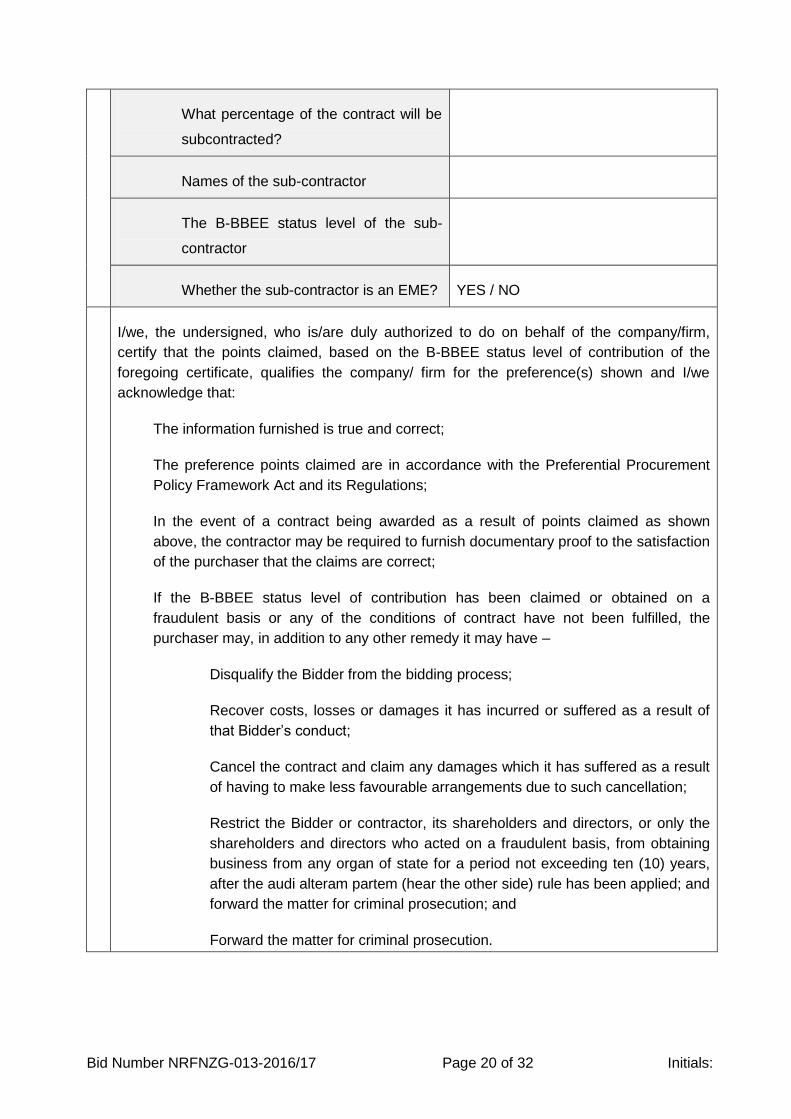
What percentage of the contract will be
subcontracted?
Names of the sub-contractor
The B-BBEE status level of the sub-
contractor
Whether the sub-contractor is an EME? YES / NO
I/we, the undersigned, who is/are duly authorized to do on behalf of the company/firm,
certify that the points claimed, based on the B-BBEE status level of contribution of the
foregoing certificate, qualifies the company/ firm for the preference(s) shown and I/we
acknowledge that:
The information furnished is true and correct;
The preference points claimed are in accordance with the Preferential Procurement
Policy Framework Act and its Regulations;
In the event of a contract being awarded as a result of points claimed as shown
above, the contractor may be required to furnish documentary proof to the satisfaction
of the purchaser that the claims are correct;
If the B-BBEE status level of contribution has been claimed or obtained on a
fraudulent basis or any of the conditions of contract have not been fulfilled, the
purchaser may, in addition to any other remedy it may have –
Disqualify the Bidder from the bidding process;
Recover costs, losses or damages it has incurred or suffered as a result of
that Bidder’s conduct;
Cancel the contract and claim any damages which it has suffered as a result
of having to make less favourable arrangements due to such cancellation;
Restrict the Bidder or contractor, its shareholders and directors, or only the
shareholders and directors who acted on a fraudulent basis, from obtaining
business from any organ of state for a period not exceeding ten (10) years,
after the audi alteram partem (hear the other side) rule has been applied; and
forward the matter for criminal prosecution; and
Forward the matter for criminal prosecution.
Bid Number NRFNZG-013-2016/17 Page 21 of 32 Initials:
DUE DILIGENCE REQUIREMENTS
Contactable References
The bidder is required to supply at least two (2) reference letters as per the format under
the Annexure section. The form is for those customers for whom the bidder has completed
work within the last 5 years and current work in progress. The customers are to complete
the form on their company letterhead.
The NRF may request to conduct a site visit on past projects, the bidder may be required to
provide the address for the site location(s).
Written References from South African Revenue Services for either
companies not registered in South Africa or do not have a local registered
subsidiary
Bidder is required to provide evidence of good standing with their tax office (overseas and
local).
Where the bidder is a South African citizen and meets the threshold for tax registration, the
Central Supplier Database registration provided the verification of the bidder’s tax status.
Foreign bidders, where they have a South African legal registered entity, must comply with
this requirement.
Where the foreign bidders do not have a South African legal entity, they are exempt from
this requirement. For due diligence, where their country of residence has the same
requirement of tax status, a copy of that certificate should be provided.
SBD 9: CERTIFICATE OF INDEPENDENT BID DETERMINATION
I, the undersigned, in submitting this Bid in response to the invitation for the Bid made by
the National Research Foundation, do hereby make the following statements that I certify to
be true and complete in every respect:
I have read and I understand the contents of this Certificate;
I understand that the Bid will be disqualified if this Certificate is found not to be true
and complete in every respect;
I am authorised by the Bidder to sign this Certificate, and to submit the Bid, on behalf
of the Bidder;
Each person whose signature appears on the Bid has been
authorised by the Bidder to determine the terms of, and to sign,
the Bid on behalf of the Bidder;
Bid Number NRFNZG-013-2016/17 Page 22 of 32 Initials:
For the purposes of this Certificate and the accompanying Bid, I understand that the word
“competitor” shall include any individual or organisation, other than the Bidder, whether or
not affiliated with the Bidder, who:
a) Has been requested to submit a Bid in response to this Bid invitation;
b) Could potentially submit a Bid in response to this Bid invitation, based on their
qualifications, abilities or experience; and
c) Provides the same goods and services as the Bidder and/or is in the same line of
business as the Bidder
The Bidder has arrived at the accompanying Bid independently from, and without
consultation, communication, agreement, or arrangement with any competitor. However,
communication between partners in a joint venture or consortium 3 will not be construed as
collusive bidding.
In particular, without limiting the generality of paragraphs above, there has been no
consultation, communication, agreement or arrangement with any competitor regarding:
a) Prices;
b) Geographical area where product or service will be rendered (market allocation);
c) Methods, factors or formulas used to calculate prices;
d) The intention or decision to submit or not to submit, a Bid;
e) The submission of a Bid which does not meet the specifications and conditions of
the Bid; or
f) Bidding with the intention not to win the Bid.
In addition, there have been no consultations, communications, agreements, or
arrangements with any competitor regarding the quality, quantity, specifications and
conditions or delivery particulars of the products or services to which this Bid invitation
relates.
The terms of this Bid have not been, and will not be, disclosed by the Bidder, directly or
indirectly, to any competitor, prior to the date and time of the official Bid opening or of the
awarding the bid or to the signing of the contract.
I am aware that, in addition and without prejudice to any other remedy provided to combat
any restrictive practices related to Bids and contracts, Bids that are suspicious will be
reported to the Competition Commission for investigation and possible imposition of
administrative penalties in terms of Section 59 of the Competition Act No 89 of 1998 and or
may be reported to the National Prosecuting Authority (NPA) for criminal investigation and
Bid Number NRFNZG-013-2016/17 Page 23 of 32 Initials:
or may be restricted from conducting business with the public sector for a period not
exceeding ten (10) years in terms of the Prevention and Combating of Corrupt Activities Act
No 12 of 2004 or any other applicable legislation
³ Joint venture or Consortium means an association of persons for the purpose of
combining their expertise, property, capital, efforts, skill and knowledge in an activity for the
execution of
SBD 8 - DECLARATION OF BIDDER’S PAST SCM PRACTICES
Is the Bidder or any of its directors listed on the National Treasury’s
Database of Restricted Suppliers as companies or persons prohibited
from doing business with the public sector? If Yes, furnish particulars as
an attached schedule:
YES / NO
Is the Bidder or any of its directors listed on the Register for Tender
Defaulters in terms of Section 29 of the Prevention and Combating of
Corrupt Activities Act (No 12 of 2004)? If Yes, furnish particulars as an
attached schedule:
YES / NO
Was the Bidder or any of its directors convicted by a court of law
(including a court outside of the Republic of South Africa) for fraud or
corruption during the past five years? If Yes, furnish particulars as an
attached schedule:
YES / NO
Was any contract between the Bidder and any organ of state
terminated during the past five years because of failure to perform on or
comply with the contract? If Yes, furnish particulars as an attached
schedule:
YES / NO
The Database of Restricted Suppliers and Register for Tender Defaulters resides on the
National Treasury’s website (www.treasury.gov.za) and can be accessed by clicking on its
link at the bottom of the home page.
SBD 4 - DECLARATION OF INTEREST WITH GOVERNMENT
Any legal person, including persons employed by the State¹, or persons having a kinship
with persons employed by the State, including a blood relationship, may make an offer or
offers in terms of this invitation to Bid (includes an advertised competitive Bid, a limited Bid,
a proposal or written price quotation). In view of possible allegations of favouritism, should
the resulting Bid, or part thereof, be awarded to persons employed by the State, or to
persons connected with or related to them, it is required that the Bidder or his/her
authorised representative, declare his/her position in relation to the evaluating/adjudicating
authority where:

Bid Number NRFNZG-013-2016/17 Page 24 of 32 Initials:
The Bidder is employed by the State; and/or
The legal person on whose behalf the Bidding Document is signed, has a
relationship with persons/s person who is/are involved in the evaluation and or
adjudication of the Bid(s), or where it is known that such a relationship exists
between the person or persons for or on whose behalf the declarant acts and
persons who are involved with the evaluation and/or adjudication of the Bid.
In order to give effect to the above, the following questionnaire must be completed and
submitted with this Bid:
Full Name of Bidder or his/her representative
Identity Number:
Position occupied in the Company (director, trustee, shareholder, member):
Registration number of company, enterprise, close corporation, partnership agreement
Tax Reference Number:
VAT Registration Number:
The names of all directors/trustees/shareholders/members, their individual identity
numbers, tax reference numbers and, if applicable, employee/PERSAL numbers must be
indicated in a separate schedule including the following questions:
Schedule attached with the above details for all directors/members/shareholders
Are you or any person connected with the Bidder presently employed
by the state? If so, furnish the following particulars in an attached
schedule
YES / NO
Name of person/ director/ trustee/ shareholder/member:
Name of state institution at which you or the person connected to the Bidder is employed
Position occupied in the state institution
Any other particulars:
Bid Number NRFNZG-013-2016/17 Page 25 of 32 Initials:
If you are presently employed by the State, did you obtain the
appropriate authority to undertake remunerative work outside
employment in the public sector?
YES / NO
If Yes, did you attach proof of such authority to the Bid document?
If No, furnish reasons for non-submission of such proof as an attached schedule
(Note: Failure to submit proof of such authority, where applicable, may result in the
disqualification of the Bid.)
Did you or your spouse or any of the company’s directors/ trustees
/shareholders /members or their spouses conduct business with the
State in the previous twelve months?
YES / NO
If so, furnish particulars as an attached schedule:
Do you, or any person connected with the Bidder, have any relationship
(family, friend, other) with a person employed by the State and who
may be involved with the evaluation and or adjudication of this Bid?
YES / NO
If so, furnish particulars as an attached schedule.
Do you or any of the directors/ trustees/ shareholders/ members of the
company have any interest in any other related companies whether or
not they are bidding for this contract?
YES / NO
If so, furnish particulars as an attached schedule:
OBLIGATIONS OF EACH PARTY
National Research Foundation
1. Contract Management
1.1. The NRF manages this contract fairly and objectively in accordance to the terms
and conditions set out in this document.
2. Contract Manager
2.1. The NRF appoints a contract manager and notifies the other party in writing of
the name and contact details of the appointed contract manager.
3. Contract Communication
3.1. The NRF communicates all communications in writing as well as through email.
Bid Number NRFNZG-013-2016/17 Page 26 of 32 Initials:
3.2. The NRF maintains all contract documentation, correspondence, etc. in a
defined contract file open for inspection.
3.3. The NRF states the contract number with secondary reference numbers i.e.
purchase numbers on all communication, documentation such as purchase
orders issued, etc. The NRF will consider any communication without the
contract number on as not being legal communication between the parties and
not enacted on by either party as a protection against fraud.
4. Communicating “As and When” in terms of the specific contract clauses
4.1. Where prices and/or availability need to be confirmed, a request for an updated
detail quotation/information is issued;
4.2. Where specific procurement items as specified in the contract are required, the
NRF issues a purchase order stating the contract number for the requirement.
4.3. Such purchase order has the following detail (where this is not provided, the
purchase order is not a valid communication in terms of this contract):
4.3.1. Purchase Order Number
4.3.2. Contract Number
4.3.3. Quantity
4.3.4. Description of the required procurement. Where detailed, reference must be
made to the relevant technical document attached;
4.3.5. Catalogue number if applicable;
4.3.6. Unit price per this contract;
4.3.7. Delivery Date;
4.3.8. Business unit code; and
4.3.9. The specific delivery site.
5. Communicating where incidental services are required as listed in this
document
5.1. Incidental services are specified in the incidental services clause
5.2. Incidental services are priced in accordance with the incidental clause where
such prices have not been set in the SBD form.
6. Performance Management
6.1. The NRF measures performance throughout the contract life.
6.2. The NRF has regular performance review with the contractor.
6.3. Where severe non-performance occurs will terminate the contract earlier in
consultation with the contractor.
PERFORMANCE LEVELS
Service being Measured Measurement Minimum level
Adherence to construction program Construction programme
timelines
Complete work within
agreed timelines
Quality of workmanship Specifications and SANS
standards
Adherence to the
applicable SANS
Bid Number NRFNZG-013-2016/17 Page 27 of 32 Initials:
standards and Project
specifications
CONTRACTED BIDDER
1. Managing the Contract
1.1. The contracted party manages this contract fairly and objectively in accordance
to the terms and conditions set out in this document.
2. Contract Manager
2.1. The contracted party appoints a contract manager and notifies the NRF in writing
of the name and contact details of the appointed contract manager.
3. Communication
3.1. The contracted party sends all formal communication in writing through email or
hand delivery only.
3.2. The contracted party always state the contract number on communication,
documentation such as correspondence, purchase orders issued, etc. and will
not act upon any communication without the contract number or must verify such
communication with the NRF prior to acting upon it.
4. Managing Stages (if applicable), Delivery Scheduling (if applicable), Milestones
(if applicable)
4.1. Where different stages apply, the contracted party communicates in writing the
commencement of the stage to the NRF.
5. Health and Safety Requirements
5.1. In terms of the Occupational Health and Safety Act (OHS Act No 85 of 1993 and
its Regulations), the contracted supplier is responsible for the health and safety
of its employees and those other people affected by the operations of the
supplier.
5.2. The contracted supplier ensures all work performed and/or equipment used on
site complies with the Occupational Health and Safety Act (OHS Act No 85 of
1993 and its Regulations).
5.3. To this end, the contracted supplier shall make available to NRF the valid letter
of good conduct and shall ensure that its validity does not expire while executing
this bid.
5.4. [NOTE TO PREPARERS:] Additional Health and Safety documentation can be
required prior to commencement of the contract but mentioned at the bid stage.
These include SHE Plan (Safety, Health and Environment Plan), SHE File which
contains the names of people assigned for Safety responsibilities and their
certificates, this may also include information regarding the organisational safety
hierarchy – line of command, and contingency plans.
Bid Number NRFNZG-013-2016/17 Page 28 of 32 Initials:
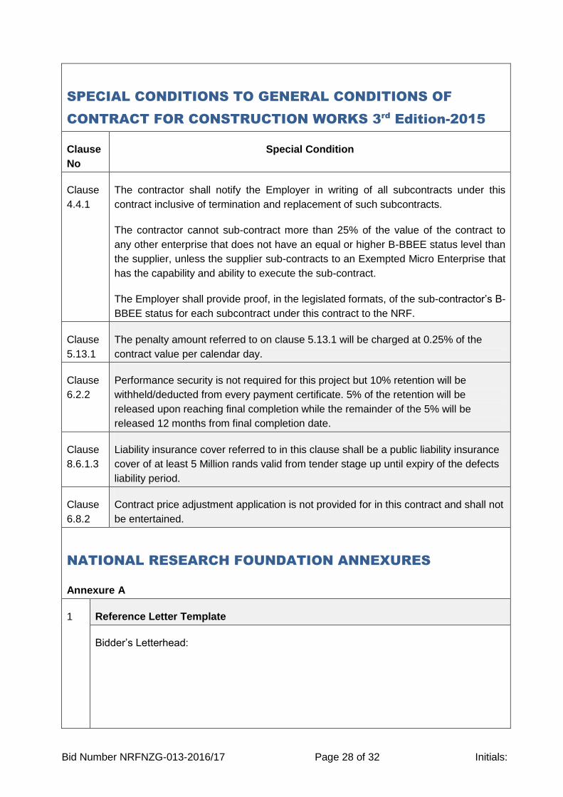
SPECIAL CONDITIONS TO GENERAL CONDITIONS OF
CONTRACT FOR CONSTRUCTION WORKS 3rd
Edition-2015
Clause
No
Special Condition
Clause
4.4.1
The contractor shall notify the Employer in writing of all subcontracts under this
contract inclusive of termination and replacement of such subcontracts.
The contractor cannot sub-contract more than 25% of the value of the contract to
any other enterprise that does not have an equal or higher B-BBEE status level than
the supplier, unless the supplier sub-contracts to an Exempted Micro Enterprise that
has the capability and ability to execute the sub-contract.
The Employer shall provide proof, in the legislated formats, of the sub-contractor’s B-
BBEE status for each subcontract under this contract to the NRF.
Clause
5.13.1
The penalty amount referred to on clause 5.13.1 will be charged at 0.25% of the
contract value per calendar day.
Clause
6.2.2
Performance security is not required for this project but 10% retention will be
withheld/deducted from every payment certificate. 5% of the retention will be
released upon reaching final completion while the remainder of the 5% will be
released 12 months from final completion date.
Clause
8.6.1.3
Liability insurance cover referred to in this clause shall be a public liability insurance
cover of at least 5 Million rands valid from tender stage up until expiry of the defects
liability period.
Clause
6.8.2
Contract price adjustment application is not provided for in this contract and shall not
be entertained.
NATIONAL RESEARCH FOUNDATION ANNEXURES
Annexure A
1 Reference Letter Template
Bidder’s Letterhead:
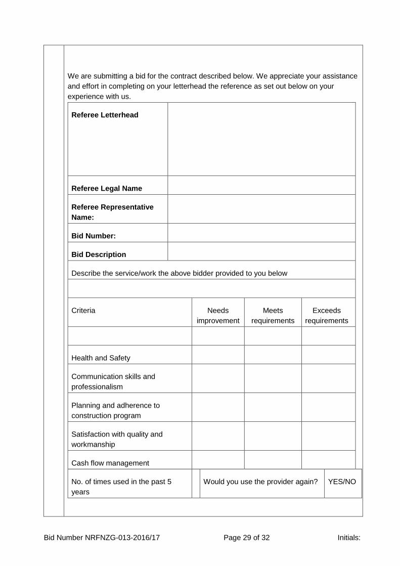
Bid Number NRFNZG-013-2016/17 Page 29 of 32 Initials:
We are submitting a bid for the contract described below. We appreciate your assistance
and effort in completing on your letterhead the reference as set out below on your
experience with us.
Referee Letterhead
Referee Legal Name
Referee Representative
Name:
Bid Number:
Bid Description
Describe the service/work the above bidder provided to you below
Criteria Needs
improvement
Meets
requirements
Exceeds
requirements
Health and Safety
Communication skills and
professionalism
Planning and adherence to
construction program
Satisfaction with quality and
workmanship
Cash flow management
No. of times used in the past 5
years
Would you use the provider again? YES/NO

Bid Number NRFNZG-013-2016/17 Page 30 of 32 Initials:
Completed by:
Signature:
Company Name:
Contact Telephone Number:
Date:
Company Stamp:
BID SUBMISSION CERTIFICATE FORM - (SBD 1)
I hereby undertake to supply all or any of the goods, works, and services described in
this procurement invitation to the National Research Foundation in accordance with the
requirements and specifications stipulated in this Bid Invitation document at the price/s
quoted.
My offer remains binding upon me and open for acceptance by the National Research
Foundation during the validity period indicated and calculated from the closing time of
Bid Invitation.
The following documents are deemed to form and be read and construed as part of this
offer / bid even where integrated in this document:
Invitation to Bid (SBD 1) Specification(s) set out in this Bid Invitation
inclusive of any annexures thereto
Bidder’s responses to specifications,
capability requirements and capacity
as attached to this document
Pricing Schedule(s) (SBD3) including
detailed schedules attached
CSD / Tax clearance letter
Declaration of Interest (SBD4); Independent Price Determination (SBD 9)
Bid Number NRFNZG-013-2016/17 Page 31 of 32 Initials:
Preference (SBD 6.1) claims for Broad Based Black Economic Empowerment
Status Level of Contribution in terms of the Preferential Procurement Regulations
2011 (SBD6.1) and the BBBEE certificate
Declaration of Bidder’s past SCM
practice (SBD 8)
Conditions of contract as set out in this
document (GCC)
NIPP Obligations (SBD 5) where
applicable
Local Content Certification (SBD 6.2) where
applicable
I confirm that I have satisfied myself as to the correctness and validity of my offer / bid in
response to this Bid Invitation; that the price(s) and rate(s) quoted cover all the goods,
works and services specified in the Bid Invitation; that the price(s) and rate(s) cover all
my obligations and I accept that any mistakes regarding price(s) and rate(s) and
calculations will be at my own risk.
I accept full responsibility for the proper execution and fulfilment of all obligations and
conditions devolving on me in terms of this Bid Invitation as the principal liable for the
due fulfilment of the subsequent contract if awarded to me.
I declare that I have had no participation in any collusive practices with any Bidder or any
other person regarding this or any other Bid.
I certify that the information furnished in these declarations (SBD4, SBD6.1, SBD 6.2
where applicable, SBD5, SBD8, SBD9) is correct and I accept that the NRF may reject
the Bid or act against me should these declarations prove to be false.
I confirm that I am duly authorised to sign this offer/ bid response.
NAME
(PRINT)
CAPACITY
SIGNATURE
Witness 1
NAME
SIGNATURE
Witness 2
NAME

Bid Number NRFNZG-013-2016/17 Page 32 of 32 Initials:
SIGNATURE
DATE

NRFNZG-013-2016/17
Page 1 of 16
NATIONAL RESEARCH FOUNDATION/
NATIONAL ZOOLOGICAL GARDENS OF SOUTH AFRICA
APPOINTMENT OF A CONTRACTOR FOR THE
CONSTRUCTION OF MASONRY BOUNDARY WALL, GATES
& PARAPLEGIC LIFT FACILITIES
MINIMUM GRADING REQUIRED: 5GB or 4GBPE
Bid No: NRFNZG-013-2016/17
TENDER DOCUMENT - VOLUME 2: PRICING
TENDERER ………………………………………………………………………………….
AMOUNT TENDERED ………….………………………………………………………….
AMOUNT IN WORDS…………………………………………………………………………
CIDB GRADING………………………………………………………………………….……
BID CLOSING : 19 December 2016

NRFNZG-013-2016/17
Page 2 of 16
TABLE OF CONTENTS:
Part C2: Pricing Data
C2.1: Bill of Quantities and Preambles Page 4

NRFNZG-013-2016/17
Page 3 of 16
PART C2:
PRICING DATA
NRFNZG-013-2016/17
Page 4 of 16
Part C2.1
Bill of Quantities
1. PREAMBLES TO THE BILL OF QUANTITIES
Preambles to the Bill of Quantities is included to assist the contractor in pricing the
various items within the Bills notwithstanding the content of the bills of contractors’
attention is referred to the other contract document viz, the Form of Tender, the
Conditions of Contract and the Specifications which are to be read in conjunction with
the Bills.
2. PRICES
A price must be entered against each item in the bill. Items against which has not
been entered shall be considered as being covered by other itemized items as listed
by the tenderer in the bill.
The prices in the bill of quantities shall fully reflect the contractor’s proposed method
of working as separately identified in detail elsewhere in its’ tender submission.
NOTE; ALL PRICES INSERTED SHALL BE EXCLUSIVE OF VAT. The VAT amount
shall be included by the tenderer as a single sum where indicated on the form of
tender. All prices, however, include for all other duties, taxes and all other obligations
arising from the conditions of tender.
The prices inserted in the bill of quantities shall be the full inclusive value of the work
as described under the items, including all costs and expenses which may be
required in an for the speedy, efficient and safe execution of the work described
together with all general risks, liabilities and obligations set forth or implied in these
documents on which the tender submission is based.
The prices are deemed to include (unless otherwise specifically stated in the bill of
quantities or herein) but shall be not limited to the following:
- Materials and consumables, including waste, necessary for the completion of
the work.
- Receiving, checking and inspecting for defects before incorporation into the
works.
NRFNZG-013-2016/17
Page 5 of 16
- Storing and protecting against deterioration, contamination, loss or damage,
including the provision for any necessary pallets, racks, waterproof sheeting,
etc.
- Transportation from the point of delivery, placing in position, fixing, assembly
of components, adjustment, lubrication and the like, all in accordance with the
works standards.
- Provision and use of contractors’ and/or supplied equipment.
- Overhead charges and profit.
- Overtime working necessary to complete the works in accordance with the
completion date.
- Payments to labour in respect of time worked and all other payments and
costs relating to labour of any denomination.
- Stoppage for inspection purposes by the engineer or other authorized
company personnel.
- Protecting all services.
- Extension of all temporary services of every kind as required to facilitate the
progress of the works.
- Transportation, erection and subsequent removal of all temporary supports,
working platforms, hard standings, scaffolding and associated works
necessary for the safe execution of the works.
- Removal and disposal of contractors’ plant and equipment off site.
- Maintenance of all temporary equipment used and/or installed by the
contractor.
3. BILL OF QUANTITIES
Included herein is a bill of quantities which the tenderer must complete and which will
be used for any additional work to be performed. THE CLIENT RESERVES THE
RIGHT TO OMIT OR ADD ANY ITEM AS PRICED FOR IN THIS BILL OF
QUANTITIES
NRFNZG-013-2016/17
Page 6 of 16
PRELIMINARY & GENERAL
ITEM NO.
PAYMENT REF.
DESCRIPTION UNIT QTY RATE (ZAR) AMOUNT (ZAR)
1.0 SABS 1200 A
PRELIMINARY & GENERAL
8.3 FIXED CHARGE ITEMS
1.1 8.3.1 Contractual requirements L/Sum 1
8.3.2 Establish facilities on site
a) Facilities for Engineer
1.2 2 nameboards L/Sum 1
b) Facilities for Contractor
1.3 Offices and storage sheds L/Sum 1
1.4 Workshops L/Sum 1
1.5 Living accommodation L/Sum 1
1.6 Ablution and latrine facilities L/Sum 1
1.7 Tools and equipment L/Sum 1
1.8 Water supplies, electric power and communications L/Sum 1
1.9 Plant for concrete mixing L/Sum 1
1.10 8.3.3 Other fixed charge obligations L/Sum 1
1.11 8.3.4 Remove Contractor's site establishment on completion L/Sum 1
8.4 TIME RELATED ITEMS
1.12 8.4.1 Contractual requirements L/Sum 1
8.4.2 Operate and maintain facilities on the site
b) Facilities for Contractor for duration of construction period
1.13 Offices and storage sheds L/Sum 1
1.14 Workshops L/Sum 1
1.15 Living accommodation L/Sum 1
1.16 Ablution and latrine facilities L/Sum 1
1.17 Tools and equipment L/Sum 1
1.18 Water supplies, electric power and communications L/Sum 1
1.19 Plant for concrete mixing L/Sum 1
1.20 8.4.3 Supervision L/Sum 1
1.21 8.4.4 Company and head office overhead costs L/Sum 1
1.22 8.4.5 Other time related obligations L/Sum 1
8.8 TEMPORARY WORKS
8.8.2 Accommoation of traffic and creation of temporary deviations
TOTAL CARRIED FORWARD
NRFNZG-013-2016/17
Page 7 of 16
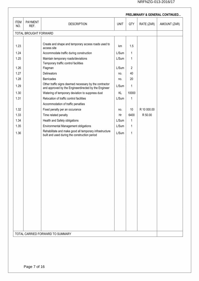
PRELIMINARY & GENERAL CONTINUED...
ITEM NO.
PAYMENT REF.
DESCRIPTION UNIT QTY RATE (ZAR) AMOUNT (ZAR)
TOTAL BROUGHT FORWARD
1.23 Create and shape and temporary access roads used to access site
km 1.5
1.24 Accommodate traffic during construction L/Sum 1
1.25 Maintain temporary roads/deviations L/Sum 1
Temporary traffic control facilities
1.26 Flagman L/Sum 2
1.27 Delineators no. 40
1.28 Barricades no. 20
1.29 Other traffic signs deemed necessary by the contractor and approved by the Engineerdirected by the Engineer
L/Sum 1
1.30 Watering of temporary deviation to suppress dust KL 10000
1.31 Relocation of traffic control facilities L/Sum 1
Accommodation of traffic penalties
1.32 Fixed penalty per an occurance no. 10 R 10 000.00
1.33 Time related penalty Hr 6400 R 50.00
1.34 Health and Safety obligations L/Sum 1
1.35 Environmental Management obligations L/Sum 1
1.36 Rehabilitate and make good all temporary infrastructure built and used during the construction period
L/Sum 1
TOTAL CARRIED FORWARD TO SUMMARY
NRFNZG-013-2016/17
Page 8 of 16
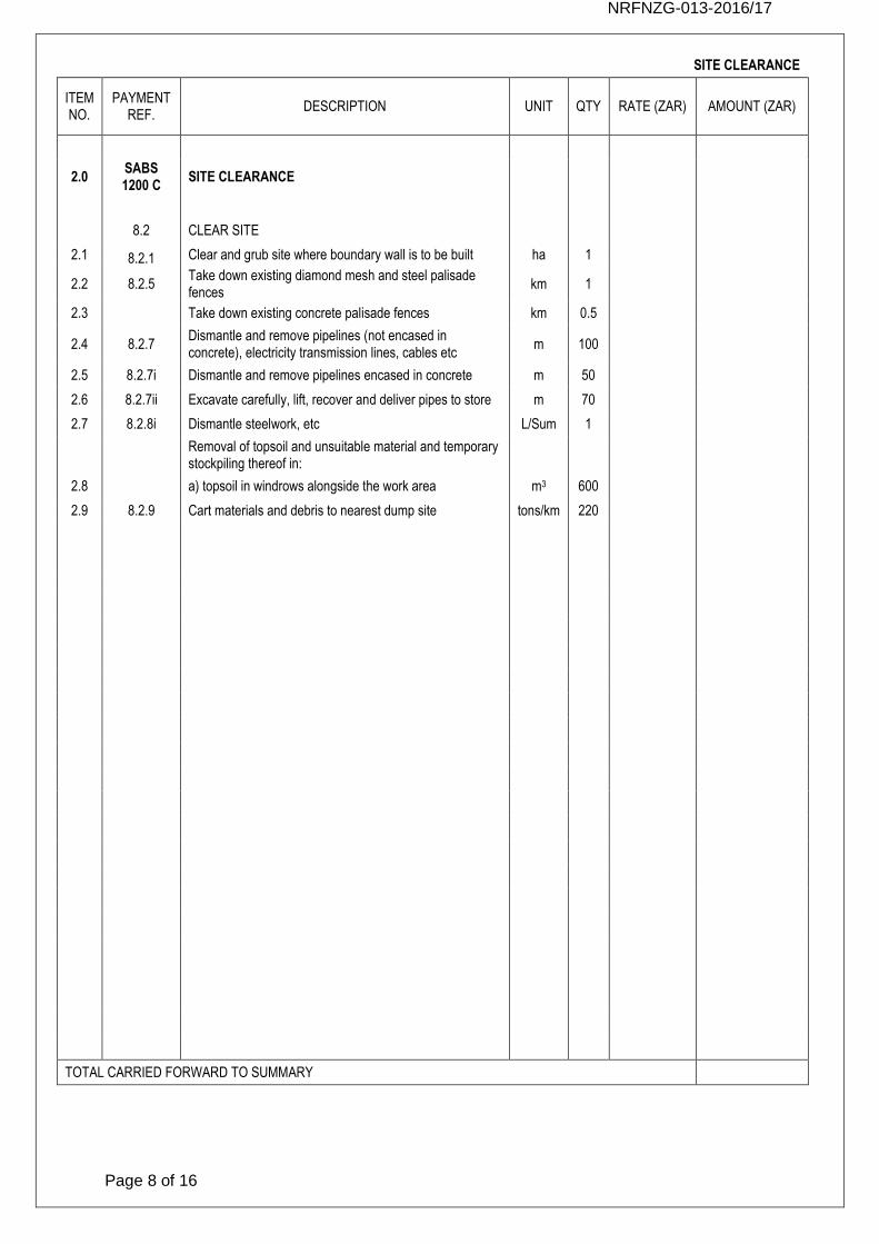
SITE CLEARANCE
ITEM NO.
PAYMENT REF.
DESCRIPTION UNIT QTY RATE (ZAR) AMOUNT (ZAR)
2.0 SABS 1200 C
SITE CLEARANCE
8.2 CLEAR SITE
2.1 8.2.1 Clear and grub site where boundary wall is to be built ha 1
2.2 8.2.5 Take down existing diamond mesh and steel palisade fences
km 1
2.3 Take down existing concrete palisade fences km 0.5
2.4 8.2.7 Dismantle and remove pipelines (not encased in concrete), electricity transmission lines, cables etc
m 100
2.5 8.2.7i Dismantle and remove pipelines encased in concrete m 50
2.6 8.2.7ii Excavate carefully, lift, recover and deliver pipes to store m 70
2.7 8.2.8i Dismantle steelwork, etc L/Sum 1
Removal of topsoil and unsuitable material and temporary stockpiling thereof in:
2.8 a) topsoil in windrows alongside the work area m3 600
2.9 8.2.9 Cart materials and debris to nearest dump site tons/km 220
TOTAL CARRIED FORWARD TO SUMMARY
NRFNZG-013-2016/17
Page 9 of 16
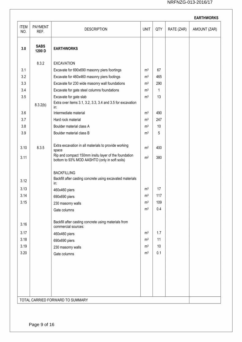
EARTHWORKS
ITEM NO.
PAYMENT REF.
DESCRIPTION UNIT QTY RATE (ZAR) AMOUNT (ZAR)
3.0 SABS 1200 D
EARTHWORKS
8.3.2 EXCAVATION
3.1
Excavate for 690x690 masonry piers foortings m3 67
3.2 Excavate for 460x460 masonry piers footings m3 465
3.3 Excavate for 230 wide masonry wall foundations m3 290
3.4 Excavate for gate steel columns foundations m3 1
3.5 Excavate for gate slab m3 13
8.3.2(b) Extra over items 3.1, 3.2, 3.3, 3.4 and 3.5 for excavation in:
3.6 Intermediate material m3 490
3.7 Hard rock material m3 247
3.8 Boulder material class A m3 10
3.9 Boulder material class B m3 5
3.10 8.3.5 Extra excavation in all materials to provide working space
m2 400
3.11 Rip and compact 150mm insitu layer of the foundation bottom to 93% MOD AASHTO (only in soft soils)
m2 380
BACKFILLING
3.12 Backfill after casting concrete using excavated materials in:
3.13 460x460 piers m3 17
3.14 690x690 piers m3 117
3.15 230 masonry walls m3 109
Gate columns m3 0.4
3.16 Backfill after casting concrete using materials from commercial sources:
3.17 460x460 piers m3 1.7
3.18 690x690 piers m3 11
3.19 230 masonry walls m3 10
3.20 Gate columns m3 0.1
TOTAL CARRIED FORWARD TO SUMMARY
NRFNZG-013-2016/17
Page 10 of 16
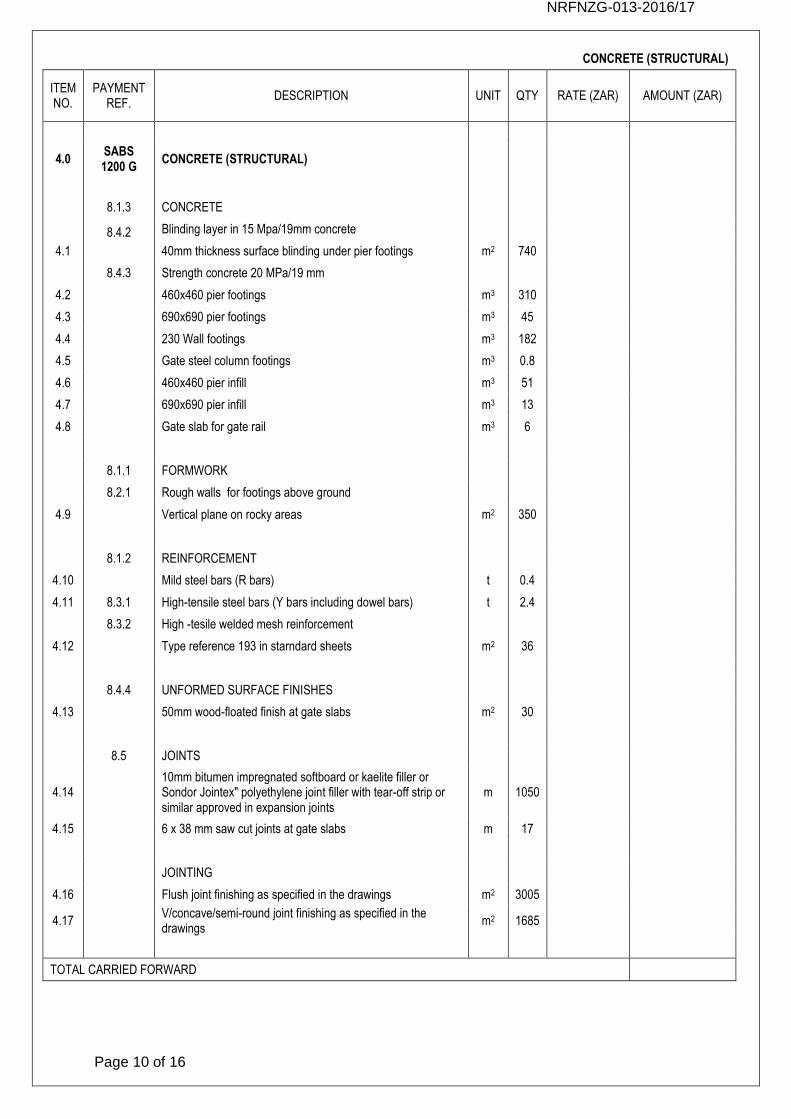
CONCRETE (STRUCTURAL)
ITEM NO.
PAYMENT REF.
DESCRIPTION UNIT QTY RATE (ZAR) AMOUNT (ZAR)
4.0 SABS 1200 G
CONCRETE (STRUCTURAL)
8.1.3 CONCRETE
8.4.2 Blinding layer in 15 Mpa/19mm concrete
4.1
40mm thickness surface blinding under pier footings m2 740
8.4.3 Strength concrete 20 MPa/19 mm
4.2 460x460 pier footings m3 310
4.3 690x690 pier footings m3 45
4.4 230 Wall footings m3 182
4.5 Gate steel column footings m3 0.8
4.6 460x460 pier infill m3 51
4.7 690x690 pier infill m3 13
4.8 Gate slab for gate rail m3 6
8.1.1 FORMWORK
8.2.1 Rough walls for footings above ground
4.9 Vertical plane on rocky areas m2 350
8.1.2 REINFORCEMENT
4.10 Mild steel bars (R bars) t 0.4
4.11 8.3.1 High-tensile steel bars (Y bars including dowel bars) t 2.4
8.3.2 High -tesile welded mesh reinforcement
4.12 Type reference 193 in starndard sheets m2 36
8.4.4 UNFORMED SURFACE FINISHES
4.13 50mm wood-floated finish at gate slabs m2 30
8.5 JOINTS
4.14 10mm bitumen impregnated softboard or kaelite filler or Sondor Jointex" polyethylene joint filler with tear-off strip or similar approved in expansion joints
m 1050
4.15 6 x 38 mm saw cut joints at gate slabs m 17
JOINTING
4.16 Flush joint finishing as specified in the drawings m2 3005
4.17 V/concave/semi-round joint finishing as specified in the drawings
m2 1685
TOTAL CARRIED FORWARD
NRFNZG-013-2016/17
Page 11 of 16
CONCRETE (STRUCTURAL) CONTINUED...
ITEM NO.
PAYMENT REF.
DESCRIPTION UNIT QTY RATE (ZAR) AMOUNT (ZAR)
TOTAL BROUGHT FORWARD
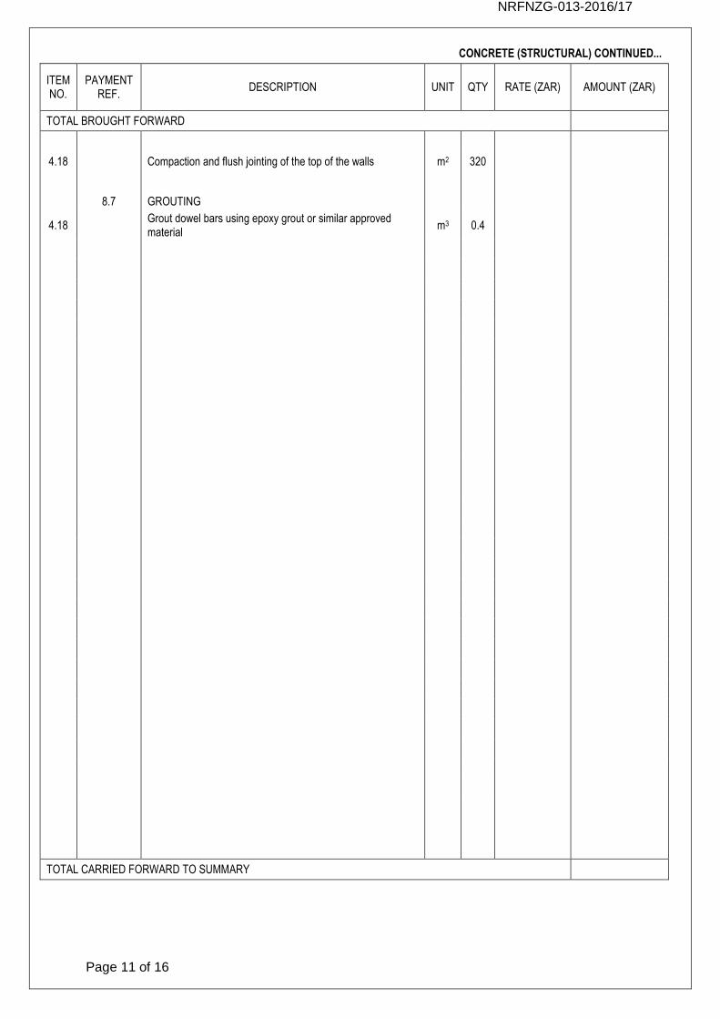
4.18 Compaction and flush jointing of the top of the walls m2 320
8.7 GROUTING
4.18 Grout dowel bars using epoxy grout or similar approved material
m3 0.4
TOTAL CARRIED FORWARD TO SUMMARY
NRFNZG-013-2016/17
Page 12 of 16
BRICKWORK
ITEM NO.
PAYMENT REF.
DESCRIPTION UNIT QTY RATE (ZAR) AMOUNT (ZAR)
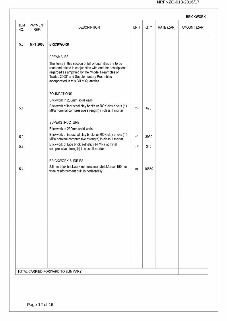
5.0 MPT 2008 BRICKWORK
PREAMBLES
The items in this section of bill of quantities are to be read and priced in conjunction with and the descriptions regarded as amplified by the "Model Preambles of Trades 2008" and Supplementary Preambles incorporated in this Bill of Quantities
FOUNDATIONS
Brickwork in 230mm solid walls
5.1 Brickwork of industrial clay bricks or ROK clay bricks (14 MPa nominal compressive strength) in class II mortar
m2 670
SUPERSTRUCTURE
Brickwork in 230mm solid walls
5.2 Brickwork of industrial clay bricks or ROK clay bricks (14 MPa nominal compressive strength) in class II mortar
m2 3930
5.3 Brickwork of face brick aethetic (14 MPa nominal compressive strength) in class II mortar
m2 345
BRICKWORK SUDRIES
5.4 2.5mm thick brickwork reinforcement/brickforce, 150mm wide reinforcement built in horizontally
m 16560
TOTAL CARRIED FORWARD TO SUMMARY
NRFNZG-013-2016/17
Page 13 of 16
MISCALLANEOUS
ITEM NO.
PAYMENT REF.
DESCRIPTION UNIT QTY RATE (ZAR) AMOUNT (ZAR)
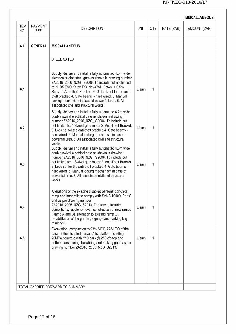
6.0 GENERAL MISCALLANEOUS
STEEL GATES
6.1
Supply, deliver and install a fully automated 4.5m wide electrical sliding steel gate as shown in drawing number ZA2016_2006_NZG_ S2006. To include but not limited to: 1. D5 EVO Kit 2x TX4 Nova7AH Bat4m + 0.5m Rack. 2. Anti-Theft Bracket D5. 3. Lock set for the anti-theft bracket. 4. Gate beams - hard wired. 5. Manual locking mechanism in case of power failures. 6. All associated civil and structural works.
L/sum 1
6.2
Supply, deliver and install a fully automated 4.2m wide double swivel electrical gate as shown in drawing number ZA2016_2006_NZG_ S2006. To include but not limited to: 1.Swivel gate motor 2. Anti-Theft Bracket. 3. Lock set for the anti-theft bracket. 4. Gate beams - hard wired. 5. Manual locking mechanism in case of power failures. 6. All associated civil and structural works.
L/sum 1
6.3
Supply, deliver and install a fully automated 4.5m wide double swivel electrical gate as shown in drawing number ZA2016_2006_NZG_ S2006. To include but not limited to: 1.Swivel gate motor 2. Anti-Theft Bracket. 3. Lock set for the anti-theft bracket. 4. Gate beams - hard wired. 5. Manual locking mechanism in case of power failures. 6. All associated civil and structural works.
L/sum 1
6.4
Alterations of the existing disabled persons' concrete ramp and handrails to comply with SANS 10400: Part S and as per drawing number ZA2016_2005_NZG_S2013. The rate to include demolitions, rubble removal, construction of new ramps (Ramp A and B), alteration to existing ramp C), rehabilitation of the garden, signage and parking bay markings.
L/sum 1
6.5
Excavation, compaction to 93% MOD AASHTO of the base of the disabled persons' list platform, casting 20MPa concrete with Y10 bars @ 250 c/c top and bottom bars, curing, backfilling and making good as per drawing number ZA2016_2005_NZG_S2013.
L/sum 1
TOTAL CARRIED FORWARD TO SUMMARY
NRFNZG-013-2016/17
Page 14 of 16
PARAPLEGIC LIFT
ITEM NO.
PAYMENT REF.
DESCRIPTION UNIT QTY RATE (ZAR) AMOUNT (ZAR)
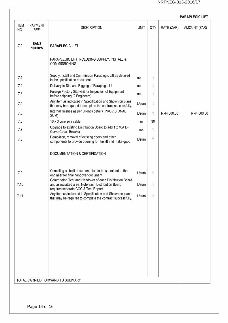
7.0 SANS
10400:S PARAPLEGIC LIFT
PARAPLEGIC LIFT INCLUDING SUPPLY, INSTALL & COMMISSIONING
7.1 Supply,Install and Commission Paraplegic Lift as detailed in the specification document
no. 1
7.2 Delivery to Site and Rigging of Paraplegic lift no. 1
7.3 Foreign Factory Site visit for Inspection of Equipment before shipping (2 Engineers)
no. 1
7.4 Any item as indicated in Specification and Shown on plans that may be required to complete the contract successfully.
L/sum 1
7.5 Internal finishes as per Client's details (PROVISIONAL SUM)
L/sum 1 R 44 000.00 R 44 000.00
7.6 16 x 3 core swa cable m 30
7.7 Upgrade to existing Distribution Board to add 1 x 40A D-Curve Circuit Breaker
no. 1
7.8 Demolition, removal of existing doors and other components to provide opening for the lift and make good.
L/sum 1
DOCUMENTATION & CERTIFICATION
7.9 Compiling as built documentation to be submitted to the engineer for final handover document
L/sum 1
7.10 Commission,Test and Handover of each Distribution Board and associatted area. Note each Distribution Board requires separate COC & Test Report.
L/sum 1
7.11 Any item as indicated in Specification and Shown on plans that may be required to complete the contract successfully.
L/sum 1
TOTAL CARRIED FORWARD TO SUMMARY
NRFNZG-013-2016/17
Page 15 of 16
SUMMARY OF SECTIONS
SECTION DESCRIPTION AMOUNT (ZAR)
SABS 1200 A PRELIMINARY & GENERAL
SABS 1200 C SITE CLEARANCE
SABS 1200 D EARTHWORKS
SABS 1200 G CONCRETE (STRUCTURAL)
MPT 2008 BRICKWORK
GENERAL MISCALLANEOUS
SANS 10400:S PARAPLEGIC LIFT
TOTAL CARRIED FORWARD TO SUMMARY
NRFNZG-013-2016/17
Page 16 of 16
SUMMARY OF TENDER
SECTION DESCRIPTION AMOUNT (ZAR)
SUB-TOTAL
10% CONTINGENCIES
SUB-TOTAL
14% VAT
TOTAL FOR TENDER
© Copyright 2016
NATIONAL RESEARCH FOUNDATION/
NATIONAL ZOOLOGICAL GARDENS OF SOUTH AFRICA
APPOINTMENT OF A CONTRACTOR FOR THE CONSTRUCTION OF
MASONRY BOUNDARY WALL, GATES & PARAPLEGIC LIFT FACILITIES
MINIMUM GRADING REQUIRED: 5GB or 4GBPE
Bid No: NRFNZG-013-2016/17
VOLUME 3: PROJECT SPECIFICATIONS
CONSTRUCTION OF MASONRY BOUNDARY WALL, GATES & PARAPLEGIC LIFT FACILITIES|
PROJECT SPECIFICATIONS|
NRFNZG-013-2016/17 Page | 2
Valid from SEPTEMBER 2016 TO FINAL COMPLETION
Name Org.-unit Date Signature
Released Moyo M. ENG_PD 2016-11-11 Signed
Revised Tshuma B.S. ENG_STR 2016-11-10 Signed
Reviewed Mokgohloa D NZG 2016-11-10 Signed
Reviewed Loyilane C NZG 2016-11-10 Signed
Released Moyo M. ENG_PD 2016-10-16 Signed
Revised Tshuma B.S. ENG_STR 2016-10-15 Signed
Reviewed Mokgohloa D NZG 2016-10-04 Signed
Reviewed Loyilane C NZG 2016-10-03 Signed
Released Moyo M. ENG_PD 2016-09-16 Signed
Reviewed Buthelezi N.M. ADM_QC 2016-09-16 Signed
Prepared Tshuma B.S. ENG_STR 2016-09-14 Signed
REVISION LOG
Doc ID Rev Rev Date By Revision Notes
ZA2016_2005_NZG_PS1000 02 2016-11-10 BT Reviewers’ comments incorporated.
ZA2016_2005_NZG_PS1000 01 2016-10-15 BT Reviewers’ comments and Paraplegic ramp specifications
incorporated.
ZA2016_2005_NZG_PS1000 00 2016-09-16 BT First issue.
CONSTRUCTION OF MASONRY BOUNDARY WALL, GATES & PARAPLEGIC LIFT FACILITIES|
PROJECT SPECIFICATIONS|
NRFNZG-013-2016/17 Page | 3
TABLE OF CONTENTS
A1 MISCELLANEOUS ....................................................................................................................... 5
A2 GENERAL DESCRIPTION OF WORK ........................................................................................ 5
A3 DRAWINGS ................................................................................................................................ 12
A4 POWER SUPPLY AND OTHER SERVICES ............................................................................. 12
A5 WATER FOR CONSTRUCTION PURPOSES........................................................................... 13
A6 CONSTRUCTION IN CONFINED AREAS ................................................................................. 13
A7 CONTRACTOR’S CAMP SITE .................................................................................................. 13
A8 SECURITY ................................................................................................................................. 13
A9 ADDITIONAL REQUIREMENTS FOR CONSTRUCTION ACTIVITIES .................................... 13
A10 SETTING OUT OF WORKS ...................................................................................................... 14
A11 PROGRAMME OF WORK ......................................................................................................... 14
A12 SITE INSTRUCTIONS ............................................................................................................... 14
A13 DUMPING SITES ....................................................................................................................... 14
A14 SOURCES OF MATERIALS ...................................................................................................... 14
PART B: MATTERS RELATING TO THE STANDARD SPECIFICATIONS .......................................... 16
ADDITIONAL PROJECT SPECIFICATIONS ......................................................................................... 21
PART C: OCCUPATIONAL HEALTH AND SAFETY ACT 1993 HEALTH AND SAFETY SPECIFICATION 21
C1 SCOPE ....................................................................................................................................... 21
C2 DEFINITIONS ............................................................................................................................. 21
C3 PROJECT DESCRIPTION ......................................................................................................... 21
C4 TENDERS .................................................................................................................................. 21
C5 NOTIFICATION OF COMMENCEMENT OF CONSTRUCTION WORK ................................... 22
C6 GUIDELINES FOR THE DEVELOPMENT OF A HEALTH & SAFETY PLAN ........................... 22
C7 HEALTH AND SAFETY FILE ..................................................................................................... 24
C8 RISK ASSESSMENT .................................................................................................................. 24
C9 APPOINTMENT OF EMPLOYEES AND SUBCONTRACTORS ............................................... 25
C10 APPOINTMENT OF SAFETY PERSONNEL ............................................................................. 26
C11 CONTRACTOR’S RESPONSIBILITIES ..................................................................................... 27
C12 PROJECT / SITE SPECIFIC REQUIREMENTS ........................................................................ 31
C13 ARRANGEMENTS FOR MONITORING AND REVIEW ............................................................ 32
PART D: ENVIRONMENTAL MANAGEMENT PLAN ............................................................................ 42
D MANAGEMENT OF CONTRACTOR ACTIVITIES DURING THE CONSTRUCTION PHASE.. 42
D.1 : CONSTRUCTION AND SITE CAMPS .......................................................................................... 48
D.2 : PROTECTION OF HERITAGE RESOURCES .............................................................................. 54
D.3 : NOISE MANAGEMENT ................................................................................................................. 57
D.4 : SOIL MANAGEMENT .................................................................................................................... 61
D.5 : AIR QUALITY MANAGEMENT...................................................................................................... 65
D.6 : WATER MANAGEMENT ............................................................................................................... 68
D.7 : WASTE MANAGEMENT ............................................................................................................... 74
D.8 : ECOLOGICAL MANAGEMENT .................................................................................................... 79
D.9 : ENVIRONMENTAL AWARENESS TRAINING ............................................................................. 84
CONSTRUCTION OF MASONRY BOUNDARY WALL, GATES & PARAPLEGIC LIFT FACILITIES|
PROJECT SPECIFICATIONS|
NRFNZG-013-2016/17 Page | 4
LIST OF CONTRACT DOCUMENTS The following documents form part of this contract:
Volume 1 : Technical document
Volume 2 : Pricing Document (Bills of quantities)
Volume 3 : Project Specifications
Volume 4 : The General Conditions of Contract (GCC), 2015
Volume 5 : The Contract Drawings. This volume will be supplied separately.
Volume 6 : Specifications for Occupational Health and Safety
Volume 7 : ASAQS Model Preambles for Trades 2008
Volume 8 : SANS 1200 Series Standard Specifications The letter of acceptance of the tender, the guarantee and all addenda issued during the tender period. The tenderer shall purchase copies of Volumes 4,7 & 8 from South African Institute of Civil Engineers and/or the SABS. SAICE TEL : (011) 805-5947 East Wing, Howick Gardens FAX : (011) 805-5971 Waterfall Park Bekker Street VORNA VALLEY X21 MIDRAND
CONSTRUCTION OF MASONRY BOUNDARY WALL, GATES & PARAPLEGIC LIFT FACILITIES|
PROJECT SPECIFICATIONS|
NRFNZG-013-2016/17 Page | 5
PART A: GENERAL
A1 MISCELLANEOUS The project specifications form an integral part of the contract documents and supplement the standard specifications. PART A: Contains a general description of the works, the site and the requirements to be met. PART B: Contains Additional Specifications consisting of Occupational Health and Safety regulations and requirements. In the event of any discrepancy with a part or parts of the standard specifications, the schedule of quantities or the drawings, the project specifications shall take precedence. The standard specifications which form part of this contract have been written to cover all phases of work normally required for structural masonry waling contracts, and they may therefore cover some items not applicable to this particular contract.
A2 GENERAL DESCRIPTION OF WORK
2.1 General Description
The site for the proposed new masonry boundary wall is located in the National Zoological Gardens of South Africa in Pretoria in the Gauteng province of South Africa. The current property of the National Zoological Gardens of South Africa is protected by a combination of concrete palisade fence; steel palisade fence and diamond mesh fences. All these fences especially the concrete palisade fence followed by the diamond mesh fences are the weakest points of security as access can be gained easily by perpetrators. On the other hand, the steel palisade fence is also targeted by those in the business of selling scrap metals. The Northern and North Eastern parts of the site are the most vulnerable to trespassers, drug mongers and any other people engaged and/or engaging in criminal activities. The National Zoological Gardens of South Africa (NZGSA) have thus decided to embark on a project to build a solid masonry wall (230mm wide by 2100mm high (minimum)) to try and put an end to these criminal acts. The NZGSA has identified the Northern part as the most critical part of the boundary wall including a small portion (approximately 125m along Boom Street on the South Eastern side of the property. The scope covers the construction of a new masonry boundary wall using ROK clay bricks or industrial clay bricks and constructing a similar boundary wall along Boom Street and Magaretha streets using face brick aesthetic on the latter. Manufacture, supply, installation and automation of steel gates also form part of the scope of work. Another component of the scope of this project is the supply and installation of a paraplegic lift at the admin building which will run from the ground floor to the first floor. This scope of work will also include alteration of the existing Paraplegic’ concrete ramp and the plinth/platform for the new Paraplegic lift.
2.2 Site Clearance
Approximately sixty five percent of the area where the boundary masonry wall is to be constructed is on very rock areas. Tall grass and shrubs are also dominant in the area. To this effect, the area has to be cleared and grubbed before excavation commencement. In some instances/areas as indicated in the drawings, diamond mesh wire must be taken down to pave way for the construction of the new boundary wall. No underground services are envisaged at the vicinity of the new boundary wall. However, an allowance has been made for this item in case the contractor encounters these underground services which may require relocation. In taking down and removing existing fences/walls, utmost care shall be observed to prevent any structural or other damage to nearby infrastructure. The Contractor shall ensure the stability of all structures during alteration work. Special care shall be exercised during the progress of the work to ensure that any electrical installations, water supply pipes, telephone and other services which may be encountered are not interfered with and notice shall be given to the Principal Agent if any disconnection or alterations become necessary. The Contractor
CONSTRUCTION OF MASONRY BOUNDARY WALL, GATES & PARAPLEGIC LIFT FACILITIES|
PROJECT SPECIFICATIONS|
NRFNZG-013-2016/17 Page | 6
shall take all precautions necessary to prevent any nuisance from dust whilst carrying out the work. The Contractor shall be responsible for the removal from the site of all materials, debris and rubbish resulting from the alterations. The Contractor shall make good in all trades to existing work where damaged or disturbed through the alterations with all necessary new materials to match the existing.
2.3 Excavations
The scope entails the excavations for the following components:
Removal of 150mm layer of topsoil
Excavation for masonry pier pad footings
Excavation for masonry wall strip footings
Excavations for gate rail slabs and steel columns
All excavated material shall be stockpiled along the excavated areas for use in backfilling operation.
2.4 Concrete (Structural)
The masonry boundary wall has two types of masonry pier namely, 460x460 piers with 20MPa concrete infill and 690x690 piers with reinforced concrete infill (20MPa). The pier foundations are 1400x1400x400DP and 2100x2100x400DP, respectively, whist the 230 masonry wall sits on a 690x250DP strip footing. Gate slabs where the rail for the sliding and swinging gates will be fixed to are 1500mm wide by 200mm thick concrete with mesh ref. 193 set 40mm above bottom of the slab. All concrete to be grade 19/20MPa. All in situ concrete work (plain and reinforced) shall comply with SANS 1200G supplemented by the Project Specification. Where SANS 1200G and the Project Specification are in conflict, the Project Specification shall take precedence.
2.5 Masonry
ROK clay bricks with a minimum compressive strength of 14MPa shall be used in the construction of the boundary wall from pier number A3 to 280. Face brick aesthetic bricks shall be used to construct the boundary wall along Boom Street. Class mortar II shall be used throughout the construction of the boundary wall. Brick force, (150mm wide) shall be installed after every three courses and below the last course of the boundary wall. The minimum height from the existing finished ground level to the top of the wall shall be 2100mm.
2.6 Steel gates
Steel gates as shown in drawing number ZA2015_2005_NZG_S2006 shall be manufactured, supplied, installed and fully automated. Refer to the BoQ for full description of the works on the steel gates. All steel shall be undercoated with the red oxide paint and then finished off with a black gloss enamel paint to protect all the steel from corrosion and the effects of weather.
2.7 Paraplegic lift
Number and type Total Number of Paraplegic Lifts - 1 off as indicated below Load Paraplegic Lifts 400kg
Speed 0,15m per second
CONSTRUCTION OF MASONRY BOUNDARY WALL, GATES & PARAPLEGIC LIFT FACILITIES|
PROJECT SPECIFICATIONS|
NRFNZG-013-2016/17 Page | 7
Travel Travel is approx. 6 Meters (max)
Stops 2 openings in a line
Power supply 230 V; 1 phase; 50 Hz Operation Simplex or Duplex full collective microprocessor based. Allow for firefighter’s operation and independent service features Control systems
(1) The lifts shall be equipped with modern technology microprocessor based control systems. Each control system shall have an advanced state-of-the-art microcomputer, which shall be used for group and individual lift car control.
(2) The control system shall be designed in such a fashion to exercise control over the various traffic flow patterns, which may be encountered in the building.
(3) A detailed description of the control systems shall be submitted with the tender.
(4) All wiring of the lift installations shall be clearly marked in accordance with the
wiring diagrams.
Shaft No shaft, housing to be constructed of aluminium structure outdoor complete with enclosures as proposed by supplier. Dimensions - 1560mm x 1560mm Head room 2270 mm (minimum) Pit depth 140mm (minimum) Car internal Supplier to quote for standard finishes. A "NO SMOKING" sign according to the regulations shall be engraved on the car operating panels. Car operating panels
(1) The lift shall be equipped with two flush mounted car-operating panels. The Engineer shall specifically approve the type and layout of the car operating panels before manufacturing thereof may commence.
(2) The panel shall be equipped with the following:
(a) Push buttons for each landing. All push buttons shall be of modern design, but shall be sufficiently robust to withstand heavy-duty vandal proof operation. All push buttons shall have raised numerals for the
CONSTRUCTION OF MASONRY BOUNDARY WALL, GATES & PARAPLEGIC LIFT FACILITIES|
PROJECT SPECIFICATIONS|
NRFNZG-013-2016/17 Page | 8
convenience of visually impaired persons. (a press and hold button will not be accepted as it is an inconvenience to the disabled people).
(b) An alarm push button. (c) A "door open" push button. (d) A "door close" push button.
(3) The bottom part of one car operating panel in the lift shall have a lockable recessed panel to accommodate the following: (a) A lift light switch. (b) A lift fan switch. (c) An inspection switch. (d) An independent control key switch. (e) An "ON/OFF" switch.
(4) The push buttons for selecting a level shall utilize solid-state electronic technology and light emitting diodes (LED's) for illumination. The push buttons shall il-luminate when a call is registered and shall remain illuminated until a call has been answered.
(5) The alarm push button shall be identified with an international accepted symbol.
The alarm shall be connected to a 50 mm diameter alarm bell mounted
underneath the lift car.
(6) The "door open" and "door close" push buttons shall be identified with internation-
ally accepted symbols. The symbols shall be neatly engraved on the push buttons.
(7) The inspection key switch shall enable an authorized lift maintenance official to
control the lift during maintenance operations.
(8) The layout of the car operating panels and all engraving shall be approved by the Engineer before installation and for this purpose a drawing of a typical panel shall be submitted to the Engineer.
(9) The particulars of the lift as required by regulation, i.e. name, number, maximum
load and maximum number of persons, shall be engraved on the car opera-ting panels.
(10) Warning signals shall be shown on the car operating panels when an overload
situation occurs in a lift. (11) The car operating panels shall be installed at a height convenient for the use
thereof by persons in wheelchairs.
Car doors Panoramic Aluminium standard automatic swing doors. Landing doors Automatic Four-panel Centre opening 900mm wide x 2100mm high clear opening in stainless steel. To be 2-hour fire rated. To be confirmed by supplier Architraves Standard design and approved by the engineer before manufacture Maintenance 12 months free service in terms of Occupational Safety Act.
CONSTRUCTION OF MASONRY BOUNDARY WALL, GATES & PARAPLEGIC LIFT FACILITIES|
PROJECT SPECIFICATIONS|
NRFNZG-013-2016/17 Page | 9
Signals - Position indicators in the car enclosures. - Combined position indicators, lanterns and electronic gongs located at all landing
entrances, with audible level of floor. - Micro push illuminating buttons in the car-operating panel and in hall button push
plates, with brail. Machine supports Each machine will be positioned in the lift housing. Guide rails Steel tee guide rails for the cars and counterweights, with all necessary steel brackets for attaching the guide rails to the hoist way.
Terminal buffers Polyurethane or equivalent buffers for bringing the cars and counterweights to a positive stop at the extreme limits of travel should the cars, for any reason, run by the final hoist way limit switches. Sheaves All sheaves, whether counterweight, deflector or overhead, will be grooved for the correct number of hoist ropes. The sheaves to be provided with steel shafts mounted on roller bearings. Machines Machines shall be gearless permanent magnet and mounted in lift housing. Brakes The brakes to be direct acting breaks on the drum and to be electromagnetically controlled. Controllers Memory equipment will be properly shielded from line pollution. The microprocessor system will be designed to accept reprogramming with minimum system down time. A microprocessor controlled solid-state power converter will be provided to apply variable voltage to the elevator motor. The converter will during the acceleration and retardation periods, gradually change the voltage applied to the elevator motor, without interruption of power. Automatic self-levelling The elevator will be provided with automatic self-levelling that will bring the elevator car level with the floor landings + 5 mm regardless of load or direction of travel. Terminal and final limits Terminal limit switches will slow down and stop the car automatically at the terminal landings. Final limit switches will cut off the power and apply the brake automatically should the car travel beyond the terminal landings. Car operating panels The car operating panels shall be as per tenderer's requirements containing clearly legible call registration push buttons and all the auxiliary buttons and switches for the operation of the elevator. All the push buttons shall be of the micro movement type. Call registration buttons shall illuminate when pressed. All car floor buttons to be fitted with braille markings
CONSTRUCTION OF MASONRY BOUNDARY WALL, GATES & PARAPLEGIC LIFT FACILITIES|
PROJECT SPECIFICATIONS|
NRFNZG-013-2016/17 Page | 10
Landing button fixtures The push button fixtures shall be as per tenderer's requirements. The fixtures shall contain up and down call registration buttons at intermediate landings and single buttons at terminal landings. All the buttons shall be of the micro movement type arranged to illuminate when pressed. Car safeties and governors Car safeties will be provided to stop the cars when excessive speed is attained. The safeties will be operated by centrifugal speed governors located at the top of the hoist way and connected to the governors through continuous steel ropes. Switches will cut off the power to the motor and apply the brake prior to application of the safety. All safety features will conform to the Occupational Safety Act.
Car frames The car frame, which supports the car platforms and enclosures, will be of structural steel and equipped with guides and car safety devices mounted underneath the car platforms. Counter balances Structural steel frames with filler weights. Guides Sliding guides for the cars and counterweights. Electric door operators for car and hoistway doors Electric door operators for opening and closing the car and hoist way doors. VVVF controlled Glass lift doors shall consist of toughened safety glass. The equipment will consist of machines on the elevator cars, operating the car doors when the cars are stopping at a landing. The car and hoist way doors will be mechanically connected and will move simultaneously in opening and closing. The car and hoist way doors will be power opened and power closed and will be checked in opening and closing with a controlling mechanism. Each hoist way door will be provided with an interlock, which will prevent movement of the cars away from the landings until the doors are locked in the closed position. An electric contact for each car door will be provided which will prevent car movement away from the landing unless the doors are in the closed position. Switches will be provided in the elevator machine room to control the operation of the doors. The car and hoist way doors will open automatically as the car stops at a landing. The doors can be stopped and reversed during their closing motion. The door operators should be designed so that the doors can be manually opened from within the car should the main power supply fail. Light rays/infrared beam Supply infrared door detectors, with multiple beams, to cover the full height of the doors. Car platforms The platform will consist of a structural steel frame covered with suitable floor covering. The platform will rest on rubber pads, which are supported on an auxiliary steel frame, fastened to the car frame. The floor covering shall be to Architects interior Design to follow. The lift to be fitted with load cells for:
CONSTRUCTION OF MASONRY BOUNDARY WALL, GATES & PARAPLEGIC LIFT FACILITIES|
PROJECT SPECIFICATIONS|
NRFNZG-013-2016/17 Page | 11
1 Overload protection 2 Load non-stops 3 Anti nuisances Telephones Loudspeaker type telephones in the car interconnected with an intercom in the machine room and CCTV/Security room/Reception. Lighting The illumination level in the lift at floor level with the ceiling diffuser installed and the lift doors closed shall be at least 160 Lux. Fittings to be LED or T5 type fluorescent fittings.
Emergency lighting A concealed standby battery and trickle charger will be provided in the car enclosure to ensure proper functioning of the emergency light and alarm in the event of a power failure
Standby battery set The lift shall be equipped with a standby battery/battery charger set to provide power to the lift to ensure the lift car returns to Ground in the event of a power failure. Finish All materials to be anodised aluminium. All unexposed surfaces of the frames and fascias are protected with black paint. Maintenance Service period
(1) The successful contractor shall undertake the servicing of the installation covered by the contract for a period of twelve (12) months after acceptance. During this period statutory inspections shall be made by the successful tenderer's own employees, who shall be responsible for the cleaning, lubrication, adjustment and replacement of parts due to normal wear and tear.
(2) In addition, the Owner shall have the right to demand breakdown service, free of
charge, throughout the 24 hours a day, 7 days a week, for the period of twelve (12) months covered by the service period.
Maintenance contract
The successful contractor shall submit a proposed maintenance agreement for consideration.
2.8 Paraplegic ramps and signage
The Paraplegic lift will be located inside the administration building approximately twenty
meters from the reception area along the passage as indicated in drawing number
ZA2016_2005_NZG_S2013. The current Paraplegic access ramp located outside the
reception area of the administration building is not compliant to the national regulations (SANS
10400: Part S), thus need to be altered to comply to SANS 10400: Part S. In addition to the
main entrance ramp, two more ramps will be constructed along the passage before and after
the location of the Paraplegic lift where there are two steps and one step, respectively. The
width of the inside ramps shall be 1200mm. The steps in the remaining width of the passage
shall be retained. The maximum slope of the two internal ramps shall be 1:10.
CONSTRUCTION OF MASONRY BOUNDARY WALL, GATES & PARAPLEGIC LIFT FACILITIES|
PROJECT SPECIFICATIONS|
NRFNZG-013-2016/17 Page | 12
The existing main entrance ramp shall be modified as indicated in drawing number
ZA2016_2005_NZG_S2013. Because of the limited space and the significant height difference
between the main entrance landing and the natural ground level at the entrance of the ramp, a
landing will be incorporated into the new two flight ramp. The maximum gradient of the new
main entrance ramp shall be 1:12.
Ramps
The following standard requirements shall be met by ramps to be constructed:
a) Main entrance ramp to have a gradient, measured along the centre line, of not more than
1:12.
b) Internal ramps to have a gradient, measured along the centre line, of not more than 1:10.
c) All ramps to have a clear trafficable surface not less than 1.1 m wide.
d) The surfaces of all ramps to be constructed of a slip resistant material.
e) The landing of the main entrance ramp shall be not less than 1,2 m in length and have a
width of not less than that of the ramp.
f) The main entrance ramp shall be provided with handrails positioned between 850 mm and
1 000 mm above the surface of the ramp. The handrails should be so finished off as not t
o present a hazard to any person using the ramp; and follow the gradient of the ramp for
the full length of the ramp.
Indication of existence of paraplegic facilities
The existence and position of disabled person’s facilities shall be indicated as per drawing
number ZA2016_2005_NZG_S2013. The symbol(s), shall be clearly visible, to indicate to
Paraplegic the route to and the entrance to such facilities.
The size of any such symbol shall be not less than 100 mm x 100 mm, and the symbol of a
person in a wheelchair shall be in the colour yellow on a black background.
2.9 Services
All known services will be shown to the contractor upon site handover .The exact and extent of location of these services will need to be established by the contractor on site.
A3 DRAWINGS
The drawings forming part of the tender documents shall be used for tender purposes only. A full set of
construction drawings will be issued to the successful tenderer after the tender award.
Any information in the possession of the contractor necessary for the resident engineer to complete as-built drawings shall be supplied to the resident engineer before a certificate of completion will be issued.
A4 POWER SUPPLY AND OTHER SERVICES The contractor shall make all his/her own arrangements concerning the supply of electrical power and all other services. No direct payment will be made for the provision of such services. The cost thereof shall be deemed to be included in the rates and amounts tendered for the various items of work for which these services are required. However, since there is electricity on site, the contractor is expected to engage with the client on a possibility of tapping electricity from the existing network although the contractor shall be liable for the actual electricity consumption bill.
CONSTRUCTION OF MASONRY BOUNDARY WALL, GATES & PARAPLEGIC LIFT FACILITIES|
PROJECT SPECIFICATIONS|
NRFNZG-013-2016/17 Page | 13
A5 WATER FOR CONSTRUCTION PURPOSES The Contractor must make adequate provision in his/her tender for all negotiations and procurement of water for construction activities and all related costs will be deemed to be included in his tendered rates. The contractor may also approach the client to negotiate possibilities of tapping water from the existing water infrastructure within the facility.
A6 CONSTRUCTION IN CONFINED AREAS It may be necessary for the Contractor to work in confined areas but no additional payment will be made for work in “restricted areas”. The method of construction in these confined areas depends on the Contractor’s constructional plant. However, the Contractor must note that measurement and payment will be in accordance with the specified cross-sections and dimensions, and that the rates and amounts tendered will be deemed to include full compensation for any special equipment or construction methods or for any difficulty encountered in working in confined areas and narrow widths, and at or around obstructions, and that no extra payment will be made nor will any claim for payment be considered an account of these difficulties.
A7 CONTRACTOR’S CAMP SITE The Contractor shall make his/her own arrangements regarding the establishment of a camp site and housing for his construction personnel.
A8 SECURITY The Contractor shall be responsible for the security of his/her personnel and constructional plant, works and material on site on and around the site of the works and for the security of his camp, and no claims in this regard will be considered by the employer.
A9 ADDITIONAL REQUIREMENTS FOR CONSTRUCTION ACTIVITIES
9.1 Accommodation of Traffic and Execution Of Contract
The principles for lane closure may be summarised as follows:
(a) The Contractor may not commence construction activities before adequate provision has been made for accommodating traffic in accordance with the requirements of this document, the relevant drawings in the attached book of drawings and the South African Road Traffic Signs Manual (SARTSM) Volume 2 Chapter 13.
(b) The Contractor shall submit proposals in connection with directional signs to the Engineer for approval.
(c) The Contractor's tendered rates for the relevant items in the schedule of quantities shall include full compensation for all the possible additional costs, which may arise from the accommodation of traffic, and no claims for extra payment following on inconvenience caused by or as a result of the modus operandi to be followed will be considered.
(d) There are sections on the road where the construction of temporary deviations will be required. The Contractor's tendered rates for the relevant items in the schedule of quantities shall include full compensation for all the possible additional costs that may arise from the accommodation of traffic, and no claims for extra payment following on inconvenience caused by or as a result of the modus operandi to be followed will be considered.
(e) The travelling public shall have the right of way on the Municipality Road and the Contractor shall apply suitable approved methods for so controlling the movement of his equipment and vehicles that they will not constitute a hazard on the road.
(f) Failure to maintain road signs, warning signs or flicker lights, etc, in a good condition shall constitute ample reason for the Engineer to bring the works to a stop until the road signs, etc., have been repaired to his satisfaction. The stipulated penalties shall be applied in the event that the contractor is in default.
(g) The Contractor shall keep the relevant Traffic Authorities fully informed of his planning in respect of the accommodation of traffic and the public.
It is important to note that under no circumstances will the road be allowed to be closed, one lane will be kept open at all times even if stop/go conditions have to be enforced or bypass have to be
CONSTRUCTION OF MASONRY BOUNDARY WALL, GATES & PARAPLEGIC LIFT FACILITIES|
PROJECT SPECIFICATIONS|
NRFNZG-013-2016/17 Page | 14
constructed. All temporary deviations shall be rehabilitated and made good by the contractor prior to de-establishment on site.
9.2 Environmental Management
The Contractor shall take the utmost care to minimise the impact of his establishment and other construction activities on the environment. The Contractor will be required to submit a Method Statement to the employer detailing his construction activities and what measures will be implemented to prevent the pollution of streams, rivers and countryside through the spilling of fuels, bituminous binders, sewage from the temporary toilets and other deleterious materials. Where in the opinion of the Engineer, the Contractor has not adhered to these requirements; the Contractor shall rectify the damage at his cost and to the satisfaction of the Engineer.
A10 SETTING OUT OF WORKS
The Contractor is required to carry out the setting out of works as required by Clause 1206 of the Standard
Specifications.
The Contractor shall ensure before any works start, the status of the existing infrastructure is clearly documented and referenced to avoid any future disputes during and after the contract.
A11 PROGRAMME OF WORK The Contractor should note the following during the preparation of his programme and during the execution of the work: The Contractor should contact the employer as early as possible, and programme for the execution of the works in accordance with the agreements reached. The Contractor is required to monitor the planning and activities related to these operations.
A12 SITE INSTRUCTIONS Due to the nature of the work, the Contractor is required to communicate very closely with the Engineer’s Representative in order that site instructions may be issued in time for their proper execution by the Contractor. Only written site instructions shall form part of the contract. Verbal instruction shall be deemed void and therefore not contractually binding unless minuted or confirmed via email or any agreed form of written communication.
A13 DUMPING SITES
The Contractor shall only dump excess or unsuitable materials at sites, which have been authorised for that purpose by the employer and/or the Tshwane Municipality. Such dump excess and material shall be inspected by the employer before deciding on whether the dump or material should be disposed off or can be reused. The Contractor shall locate a suitable site and shall make all arrangements and pay all levies in respect of the use of such dumping sites to the appropriate authority.
A14 SOURCES OF MATERIALS
The following sources of materials are envisaged:
14.1 Materials from commercial sources.
Materials from commercial sources are to be used for certain foundation layers and for backfill where suitable materials are not available on site. The sources are to be selected by the Contractor and submitted to the Engineer for approval. The Contractor is responsible for process control with regards to the quality of material delivered to and placed on site.
14.2 Borrow Pits

CONSTRUCTION OF MASONRY BOUNDARY WALL, GATES & PARAPLEGIC LIFT FACILITIES|
PROJECT SPECIFICATIONS|
NRFNZG-013-2016/17 Page | 15
No borrow pits are envisaged for this contract as materials shall be obtained from commercial sources as stated in Section 14.1 above.
CONSTRUCTION OF MASONRY BOUNDARY WALL, GATES & PARAPLEGIC LIFT FACILITIES|
PROJECT SPECIFICATIONS|
NRFNZG-013-2016/17 Page | 16
PART B: MATTERS RELATING TO THE STANDARD SPECIFICATIONS Notes to tenderer: 1. In certain clauses the Standard Specifications allow a choice to be specified in the project
specifications between alternative materials or methods of construction and for additional requirements to be specified to suit a particular contract. Details of such alternatives or additional requirements applicable to this contract are contained in this part of the project specifications. It also contains some additional specifications required for this particular contract.
This part of the project specifications deals with matters relating to the standard specifications. Where reference is made in the standard specifications to the project specifications this part shall also contain the relevant information e.g. the requirements where a choice of materials or construction methods are provided for in the standard specifications.
PROJECT SPECIFICATIONS REFERRING TO THE STANDARD SPECIFICATIONS AND ADDITIONAL
SPECIFICATIONS In certain clauses the standard specifications allow a choice to be specified in the project specifications between alternative materials or methods of construction and for additional requirements to be specified to suit a particular contract. Details of such alternatives or additional requirements applicable to this contract are contained in this part of the project specifications. It also contains some additional specifications and amendments of the standard specifications required for this particular contract.
WORKMANSHIP AND QUALITY CONTROL
“The contractor shall implement a quality assurance system in accordance with ISO 9002 and appoint a quality manager who shall ensure that members of the contractor’s staff comply with the requirements of the quality system. The quality system and the methods used to implement it shall be described in a quality plan produced by the contractor. The quality manager shall be resident on site full time. No construction activities shall take place on site before the engineer approves the quality plan”. “The contractor shall submit the quality assurance system he proposes using to the engineer, for his approval, within two weeks of the site handover. Once accepted by the engineer the contractor shall not deviate from it unless written notification of proposed changes have similarly been submitted and approved. The system shall record the lines and levels of responsibility and indicate the method by which testing procedures will be conducted.”
THE SETTING OUT OF WORK AND PROTECTION OF BEACONS “The contractor shall take care that property beacons, trigonometrical survey beacons or setting-out beacons are not displaced or destroyed without the consent of the engineer. Property beacons and trigonometrical survey beacons that have been displaced or destroyed shall be replaced by a registered land surveyor, who shall certify such replacement. “The cost of replacing all beacons displaced or destroyed during the course of the contract without the consent of the engineer shall be the contractor’s responsibility and included in the tender rates”. NOTICES, SIGNS AND ADVERTISEMENTS “Details of the contents of the “contract notice boards” which have to be erected will be provided to the successful contractor upon award of the contract.”
PAYMENT
CONSTRUCTION OF MASONRY BOUNDARY WALL, GATES & PARAPLEGIC LIFT FACILITIES|
PROJECT SPECIFICATIONS|
NRFNZG-013-2016/17 Page | 17
"Value Added Tax (VAT) shall be excluded from the rates and provided for as a Lump Sum in the summary of the Schedule of Quantities." Engineers certificate The Engineer's certificate will be issued only after receipt by him of a draft certificate prepared by the Contractor at his own expense in the form prescribed by the Engineer. The cost of duplicating and delivering copies of the certificate to the Contractor, the Engineer and the Employer shall be borne by the Contractor. The Engineer and the Employer shall require three sets of A4-sized paper copies in total. Work in confined areas No extra payment shall be made nor shall any claim for additional payment considered for construction in confined areas. The omission of standard pay items from the schedule of quantities shall be taken to be deliberate and any additional costs incurred shall be included in the bulk rate. Rates to remain unchanged when scope of work changes Dependent on the rates and prices offered in the Pricing Schedule, the employer intends to increase or reduce the scope of work to match the budget allowed for this project. The value of such increase or reduction in the scope of works shall not give cause for the contractor to vary the offered rates and prices, which shall remain final and binding for the duration of the contract. EXTENSION OF TIME RESULTING FROM INCLEMENT WEATHER “Extension of time resulting from rainfall or other forms of inclement weather shall be established according to the requirements of Method (ii) (Critical-path method). The ‘n’ value of working days, as specified in this clause as being expected delays for which the contractor must make allowance in his programme is 7 days.
Actual delays due to inclement weather shall be agreed between the engineer’s and contractor’s representatives on the site. The agreed whole days or parts thereof shall be recorded at the monthly site meetings. Adjustment to the contract period shall only be made at the end of the contract when the contractor may submit its claim for the agreed extension due as well as any additional payment resulting from the delay. For any specific month, inclement weather extensions will only be granted if the actual inclement weather delay days (agreed between the engineer’s and the conctractor’s site representatives) exceed the ‘n’ value given in the paragraph above. If approved extensions of time extend the completion date beyond the start of the contractor’s holiday in December, the holiday period shall not be considered as working days. Any remaining extension of time at this date shall be calculated from the first statutory working day in January the following year, provided that the contractor has shown in his programme that he intends to close during the traditional Christmas/New Year break.” Water “Water for use on site other than municipal, shall be subject to the required permit from DWAF. This shall include such extraction points as rivers, dams, streams, and boreholes.”
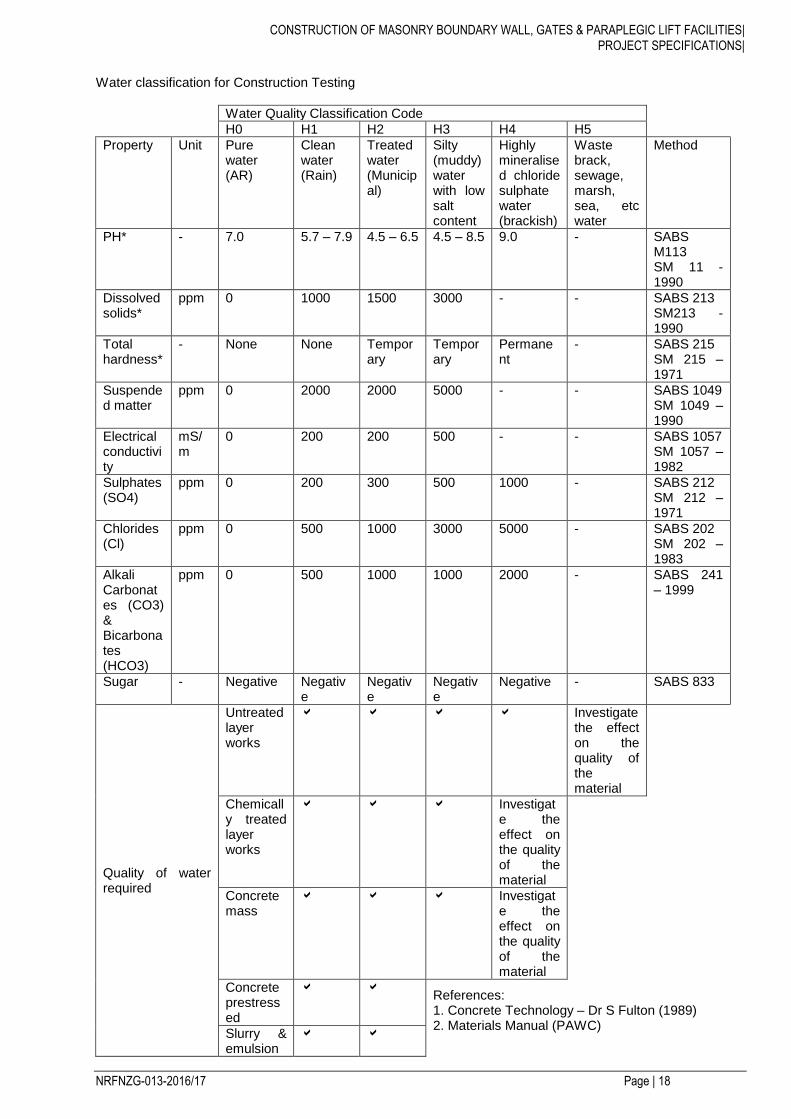
CONSTRUCTION OF MASONRY BOUNDARY WALL, GATES & PARAPLEGIC LIFT FACILITIES|
PROJECT SPECIFICATIONS|
NRFNZG-013-2016/17 Page | 18
Water classification for Construction Testing
Water Quality Classification Code
H0 H1 H2 H3 H4 H5
Property Unit Pure water (AR)
Clean water (Rain)
Treated water (Municipal)
Silty (muddy) water with low salt content
Highly mineralised chloride sulphate water (brackish)
Waste brack, sewage, marsh, sea, etc water
Method
PH* - 7.0 5.7 – 7.9 4.5 – 6.5 4.5 – 8.5 9.0 - SABS M113 SM 11 - 1990
Dissolved solids*
ppm 0 1000 1500 3000 - - SABS 213 SM213 - 1990
Total hardness*
- None None Temporary
Temporary
Permanent
- SABS 215 SM 215 – 1971
Suspended matter
ppm 0 2000 2000 5000 - - SABS 1049 SM 1049 – 1990
Electrical conductivity
mS/m
0 200 200 500 - - SABS 1057 SM 1057 – 1982
Sulphates (SO4)
ppm 0 200 300 500 1000 - SABS 212 SM 212 – 1971
Chlorides (Cl)
ppm 0 500 1000 3000 5000 - SABS 202 SM 202 – 1983
Alkali Carbonates (CO3) & Bicarbonates (HCO3)
ppm 0 500 1000 1000 2000 - SABS 241 – 1999
Sugar - Negative Negative
Negative
Negative
Negative - SABS 833
Quality of water required
Untreated layer works
Investigate the effect on the quality of the material
Chemically treated layer works
Investigate the effect on the quality of the material
Concrete mass
Investigate the effect on the quality of the material
Concrete prestressed
References: 1. Concrete Technology – Dr S Fulton (1989) 2. Materials Manual (PAWC)
Slurry & emulsion
CONSTRUCTION OF MASONRY BOUNDARY WALL, GATES & PARAPLEGIC LIFT FACILITIES|
PROJECT SPECIFICATIONS|
NRFNZG-013-2016/17 Page | 19
Soil/gravel tests
Chemical or control tests
* “A primary property. The quality of the water is that quality where all three of the primary properties are within the limits. ! “The tabulated single values are maximum value except in the case of the pH value for pure water, which must be 7.0” MATERIALS “The contractor, when using materials that are required to comply with any standard specification, shall, if so ordered, furnish the engineer with certificates showing that the materials do so comply. “Where so specified, materials shall bear the official mark of the appropriate authority. Samples ordered or specified shall be delivered to the engineer's office on the site free of charge. “Where materials are specified under trade names tenders must be based on these materials. Alternative materials may be submitted as alternative tenders and the engineer may, after receipt of tenders, approve the use of equivalent materials. The tender must be clearly marked as an alternative tender, failing which the tender may be rejected”. “Unless otherwise specified, all proprietary materials shall be used and placed in strict accordance with the relevant manufacturer's current published instructions. “Unless anything to the contrary is specified, all manufactured articles or materials supplied by the contractor for the permanent works shall be unused/new. “Existing structures on the site shall remain the property of the employer and except as and to the extent required elsewhere in the contract, shall not be interfered with by the contractor in any way. “Materials to be included in the works shall not be damaged in any way and, should they be damaged on delivery or by the contractor during handling, transportation, storage, installation or testing they shall be replaced by the contractor at his own expense. “All places where materials are being manufactured or obtained for use in the works, and all the processes in their entirety connected therewith shall be open to inspection by the engineer (or other persons authorised by the engineer) at all reasonable times, and the engineer shall be at liberty to suspend any portion of work which is not being executed in conformity with these specifications”. CONTRACTOR'S ESTABLISHMENT ON SITE AND GENERAL OBLIGATIONS General Requirements (c) Legal and Contractual Requirements and responsibilities to the public “There has been recent legislation promulgated by Government that improve mutual obligations on the employer and contractor in the performance of their duties to society and to the built and natural environment. To assist the contractor in understanding and assessing his obligations, and thus to make allowances for the cost of compliance with this legislation, the following additional specifications are included in the project specifications. Section C of the Scope of Works contains the Environmental Management Plan for this project. Its provisions regulate the contractor’s construction methods to ensure responsible conduct and treatment of the environment relevant to the project. No separate payment mechanism has been made available for the contractor to allow for his compliance with relevant environmental legislation. The contractor shall include such costs in the existing payment items under P&Gs. However, non-compliance with the provisions of this section may lead to the imposition of penalties.
CONSTRUCTION OF MASONRY BOUNDARY WALL, GATES & PARAPLEGIC LIFT FACILITIES|
PROJECT SPECIFICATIONS|
NRFNZG-013-2016/17 Page | 20
Section D of the Scope of Works contains the specifications that regulate the contractor’s construction methods so far as to ensure health and safety of his employees and of the public. New pay item has been made available under this section to allow the contractor to make separate provision for the cost of health and safety measures during the construction process.” Section 4 Part C of the Project Specification contains the specification that regulates the contractor’s construction methods so far as to ensure health and safety of his employees and of the public. New pay item has been made available under this section to allow the contractor to make separate provision for the cost of health and safety measures during the construction process” “(d) Contractor’s ablution facilities The Contractor shall, at each construction area, provide sufficient portable chemical latrine units. Furthermore the Contractor shall also provide a portable chemical toilet at each temporary traffic control facility. The latrine units shall be serviced daily and kept in a hygienic and orderly state to the approval of the Engineer. No separate payment shall be made for this requirement and the costs thereof shall be deemed to be included in the rates tendered for the Contractor’s time-related obligations. Safety of Contractor’s workforce and subcontractors The Contractor is responsible for the safety of his workforce and for the safety of the subcontractors.”
CONSTRUCTION OF MASONRY BOUNDARY WALL, GATES & PARAPLEGIC LIFT FACILITIES|
PROJECT SPECIFICATIONS|
NRFNZG-013-2016/17 Page | 21
ADDITIONAL PROJECT SPECIFICATIONS
PART C: OCCUPATIONAL HEALTH AND SAFETY ACT 1993 HEALTH AND SAFETY SPECIFICATION
C1 SCOPE
This specification covers the health and safety requirements to be fulfilled by the Contractor to ensure a continued safe and healthy environment for all workers, employees and subcontractors under his control and for all other persons entering the site of works. However, what is given hereunder does not necessarily cover all aspects. The OHS Act and hence the Contractor’s responsibility is not limited to this specification.
This specification shall be read with the Occupational Health and Safety Act (Act No 85 and
amendment Act No 181) 1993, and the corresponding Construction Regulations 2014, and all
other safety codes and specifications referred to in the said Construction Regulations. In terms of the OHS Act Agreement in Section 12 (Forms to be Completed by Successful Tenderer) of the tender document, the status of the Contractor as mandatory to the Employer (Client) is that of an employer in his own right, responsible to comply with all provisions of OHS Act 1993 and the Construction Regulations 2014. This health and safety specification and the Contractor’s own Health and Safety Plan as well as the Construction Regulations 2014, shall be displayed on site and made available for inspection by all workers, employees, inspectors and any other persons entering the site of works.
C2 DEFINITIONS For the purpose of this contract the following shall apply:
(a) “Employer” where used in the contract documents and in this specification, means the Employer as defined in the General Conditions of Contract and it shall have the exact same
meaning as “Client” as defined in the Construction Regulations 2014. “Employer” and
“Client” is therefore interchangeable and shall be read in the context of the relevant document.
(b) “Contractor”, wherever used in the contract documents and in this specification, shall have
the same meaning as “Contractor” as defined in the General Conditions of Contract.
The “Contractor” is the “Principal Contractor” in terms of the Construction Regulations
2014. The “Contractor” and “Subcontractor” are “Contractors” in terms of the Construction Regulations 2014.
For the purpose of this contract the Contractor will, in terms of OHS Act 1993, be the mandatory of the Employer, without derogating from his status as an employer in his own right.
(c) “Engineer” where used in this specification, means the Engineer as defined in the General Conditions of Contract. The Employer may appoint the Engineer or any other person to act as
his “Agent” in terms of the Construction Regulations 2003.
C3 PROJECT DESCRIPTION The work to be carried out under this contract is as described in Part A: General.
C4 TENDERS
The Contractor shall make available the following during the tender evaluation: (a) a documented Health and Safety Plan as stipulated in the Construction Regulations 2014. The
Safety Plan must be based on the Health and Safety Specification in the Project Specifications and will be subject to approval by the Employer;

CONSTRUCTION OF MASONRY BOUNDARY WALL, GATES & PARAPLEGIC LIFT FACILITIES|
PROJECT SPECIFICATIONS|
NRFNZG-013-2016/17 Page | 22
(b) a declaration to the effect that he has the competence and necessary resources to carry out the work safely in compliance with the Construction Regulations 2014; Complete Form OHS 2.
Failure to make available the foregoing with his tender or during tender evaluation, will lead to the conclusion that the Tenderer is not able to carry out the work under the contract safely in accordance with the Construction Regulations and will result in the tender being disqualified.
C5 NOTIFICATION OF COMMENCEMENT OF CONSTRUCTION WORK After award of the contract, but before commencement of construction work, the Contractor shall, in terms of Regulation 3, notify the Provincial Director of the Department of Labour in writing if the following work is involved: (a) the demolition of structures and dismantling of fixed plant of height of 3,0 m or more; (b) the use of explosives; (c) construction work that will exceed 30 days or 300 person-days; (d) excavation work deeper than 1,0 m; or (e) working at a height greater than 3,0 m above ground or landings. The notification must be done in the form of the pro forma included under Section 11 (The Occupational Health and Safety Act) of the tender document. A copy of the notification form must be kept on site, available for inspection by inspectors, Employer, Engineer, employees and persons on site.
C6 GUIDELINES FOR THE DEVELOPMENT OF A HEALTH & SAFETY PLAN
C6.01 Project Background In terms of the Construction Regulations 2014 [Regulation 4 (1) (a)] of the Occupational Health and Safety Act, No 85 of 1993, the Client is required to compile an Occupational Health and Safety specification for the construction work and the Contractor, appointed by the Client in terms of Regulation 4 (1) (c), is required to prepare an Occupational Health and Safety Plan. This plan has to be prepared in terms of Regulation 5 (1) as well as the Client’s Occupational Health & Safety Specification. In terms of Regulation 4 (2), the Client and the Contractor are required to agree on the Occupational Health and Safety Plan before any work may commence.
C6.02 Framework for an Occupational Health and Safety Plan
C6.02.1 Introduction The Contractor has to demonstrate to the Client that he has a suitable and sufficiently documented Occupational Health and Safety Plan as well as the necessary competencies, experience and resources to perform the construction work safely. The Contractor could be required to submit the following documentation for perusal and verification by the Client:
Management Structure
Quality Plan
Human Resources Plan
Registered Workplace Skills Plan
“Letter of good standing” from the Compensation Commissioner or licensed compensation insurer.
Proof of induction and other training of employees
Example copy minutes of previous Occupational Health and Safety Committee meetings and copies of Incident Investigation Reports
C6.02.2 Contents of an Occupational Health and Safety Plan
The Occupational Health and Safety Plan shall include the following:
C6.02.2.1 Occupational Health and Safety Management Programme
Management of Occupational Health and Safety risks
CONSTRUCTION OF MASONRY BOUNDARY WALL, GATES & PARAPLEGIC LIFT FACILITIES|
PROJECT SPECIFICATIONS|
NRFNZG-013-2016/17 Page | 23
Occupational Health and Safety structures and appointments
Programme of Occupational Health and Safety inspections
Occupational Health and Safety Representatives
Occupational Health and Safety committee
C6.02.2.2 Communication and Management of the Work
Management structure and responsibilities
Occupational Health and Safety objectives for the project and arrangements for monitoring and review of Occupational Health and Safety performance
Arrangements for o Regular liaison between parties on site o Consultation with the workforce o The exchange of design information between the Client, Engineer, supervisors and
subcontractors on site o Handling design changes during the project o Selection and control of subcontractors o The exchange of Occupational Health and Safety information between all
subcontractors o Security o Site induction and onsite training o Facilities and first-aid o The reporting and investigation of accidents and incidents o The production and approval of risk assessments and method statements o Site Occupational Health and Safety rules o Fire and emergency procedures o Reporting to the Client i.e. results of Occupational Health and Safety inspections,
incident o and incident investigations and committee meetings o Reporting of incidents to the Department of Labour and Compensation insurer where
appropriate
C6.02.2.3 Arrangements for controlling significant site risks The following are some examples requiring arrangements for controlling the most significant site risks: Safety risks
Services, including temporary electrical installations
Preventing employees from falling into excavations, from trucks etc.
Work with, on or near fragile materials
Control of lifting operations
The maintenance of plant and equipment
Poor ground conditions
Traffic routes and segregation of vehicles and pedestrians
Storage of hazardous materials
Dealing with existing unstable structures/land
Accommodating adjacent land use
Other significant safety risks as and when identified Health risks
Storage and use of hazardous chemical substances
Dealing with contaminated land or material
Manual handling
Reducing noise and vibration
Provision of adequate lighting
Ventilation considerations
Extreme heat and cold temperature considerations
Dealing with HIV/Aids and other illnesses
Provision of and maintaining ablution and eating facilities
Other significant health risks as and when identified
CONSTRUCTION OF MASONRY BOUNDARY WALL, GATES & PARAPLEGIC LIFT FACILITIES|
PROJECT SPECIFICATIONS|
NRFNZG-013-2016/17 Page | 24
C7 HEALTH AND SAFETY FILE
The Contractor shall in terms of Construction Regulation 5(7) maintain a Health and Safety File on site at all times. The Health and Safety File is a file or other permanent record containing information on aspects of the construction project - which will be necessary to ensure the health and safety of any person who may be affected by the construction work. The Contractor shall appoint a suitably qualified person to prepare the Health and Safety File and to keep it up to date for the duration of the contract. The Health and Safety file shall include the following information:
Notification of Construction Work (Construction Regulation 3.) (Annexure A)
Copy of OH&S Act (updated) (General Administrative Regulation 4.)
Proof of Registration and good standing with a COID Insurer (Construction Regulation 4 (g))
Copy of health and safety plan (construction regulation 5 (1)
OH&S Programme agreed with Client including the underpinning Risk Assessment and Method Statements (Construction regulation 5 (1))
Designs/drawings (Construction Regulation 5 (8))
A list of Contractors (Subcontractors) including copies of the agreements between the parties and the type of work being done by each Contractor (Construction Regulation 9)
Appointment / Designation forms required by the ACT and Regulations
Registers as follows:
o Accident/Incident Register (Annexure 1 of the General Administrative Regulations) o OH&S Representatives Inspection Register o Form/Support work Inspection o Excavations Inspection o Lifting Equipment o Demolition Inspections o Designer’s Inspection of Structures Record o Batch Plant Inspections o Arc & Gas Welding & Flame Cutting Equipment Inspections o Construction Vehicles & Mobile Plant Inspections o Electrical Installation and Machinery Inspections o Fire Equipment Inspection & Maintenance o First Aid o Hazardous Chemical Substances o Lifting Tackle and Equipment Inspections o Inspection of Cranes o Inspection of Ladders o Inspection of Vessels under Pressure o Machinery Inspections o Drivers/Operators of Mobile Plant/Construction Vehicles Daily Inspections o Accommodation of traffic daily inspection book
The Health & Safety File shall be handed over to the Client on completion of the contract. It must contain all the documentation handed to the Contractor by any subcontractors together with a record of all drawings, designs, materials used and other similar information concerning the completed project.
C8 RISK ASSESSMENT
Before commencement of any construction work during the construction period, the Contractor shall have a risk assessment performed and recorded in writing by a competent person. (Refer Regulation 7 of the Construction Regulations 2003). Risk is a measure of the likelihood that the harm from a particular hazard will be realized, taking into account the possible severity of the harm. Harm to people includes death, injury (permanent or temporary), physical or mental health or any combination thereof. Risk management in health and safety includes the identification of hazards, assessing risks, taking action to eliminate or reduce the
CONSTRUCTION OF MASONRY BOUNDARY WALL, GATES & PARAPLEGIC LIFT FACILITIES|
PROJECT SPECIFICATIONS|
NRFNZG-013-2016/17 Page | 25
risk, monitoring the effectiveness and performing regular reviews of the entire process. The Contractor shall compile method statements to address or handle the following:
Hazards particulars to contract Identify what could go wrong and how Identify the likelihood of this happening Identify the persons at risk Identify the extent of possible harm Eliminating or reducing this risk A monitoring plan A review plan
Contractors must ensure that all subcontractors conduct risk assessments for their scope of work as well. The risk assessment shall identify and evaluate the risks and hazards that may be expected during the execution of the work under the contract, and it shall include a documented plan of safe work procedures to mitigate, reduce or control the risks and hazards identified. The risk assessment shall be available on site for inspection by inspectors, Employer, Engineer, subcontractors, employees, trade unions and health and safety committee members, and must be monitored and reviewed periodically by the Contractor.
C9 APPOINTMENT OF EMPLOYEES AND SUBCONTRACTORS
C9.01 Health and Safety plan
The Contractor shall appoint his employees and any subcontractors to be employed on the contract, in writing, and he shall provide them with a copy of his documented Health and Safety Plan, or relevant sections thereof. The Contractor shall ensure that all subcontractors and employees are committed to the implementation of his Safety Plan.
C9.02 Health and safety induction training
The Contractor shall ensure that all employees under his control, including subcontractors and their employees, undergo a health and safety induction training course by a competent person before commencement of construction work. No visitor or other person shall be allowed or permitted to enter the site of the works unless such person has undergone health and safety training pertaining to hazards prevalent on site. The Contractor shall ensure that every employee or visitor on site shall at all times be in possession of proof of the health and safety induction training issued by a competent person prior to commencement of construction work.
C9.03 OH&S Training Requirements: (as required by the Construction Regulations and as indicated by the OH&S Specification and the Risk Assessment/s):
* General Induction (Section 8 of the Act) * Site/Job Specific Induction (also visitors) (Sections 8 & 9 of the Act)
* Site/Project Manager
* Construction Supervisor * OH&S Representatives (Section 18 (3) of the Act) * Training of the Appointees indicated in 3.1.1. & 3.1.2. above * Operation of Cranes (Driven Machinery Regulations 18 (11)) * Operators and Drivers of Construction Vehicles & Mobile Plant (Construction Regulation 21)
CONSTRUCTION OF MASONRY BOUNDARY WALL, GATES & PARAPLEGIC LIFT FACILITIES|
PROJECT SPECIFICATIONS|
NRFNZG-013-2016/17 Page | 26
* Basic Fire Prevention & Protection (Environmental Regulations 9 and Construction regulation 27)
* Basic First Aid (General Safety Regulations 3) * Storekeeping Methods & Safe Stacking (Construction Regulation 26) * Emergency, Security and Fire Co-ordinator
C10 APPOINTMENT OF SAFETY PERSONNEL
C10.01 Construction Supervisor
The Contractor shall appoint a full-time Construction Supervisor with the duty of supervising the performance of the construction work.
He may also have to appoint one or more competent employees to assist the construction supervisor where justified by the scope and complexity of the works.
C10.02 Construction safety officer
Subject to the decision by the Inspector of the Department of Labour and taking into consideration the size of the project and the hazards or dangers that can be expected, the Contractor shall appoint in
writing a full-time or part-time Construction Safety Officer. The Safety Officer shall have the necessary competence and resources to perform his duties diligently. Provision will be made in the schedule of quantities to cover the cost of a dedicated construction safety officer appointed after award of the contract if so ordered by the Engineer.
C10.03 Health and safety representatives
In terms of Sections 17 and 18 of the Act (OHSA 1993) the Contractor shall appoint a health and
safety representative whenever he has more than 20 employees in his employ on the works. The health and safety representative must be selected from employees who are employed in a full-time capacity at a specific workplace.
The number of health and safety representatives for a workplace shall be at least one for every 50 employees. The function of the health and safety representative(s) will be to review the effectiveness of health and safety measures, to identify potential hazards and major incidents, to examine causes of incidents (in collaboration with his employer, the Contractor), to investigate complaints by employees relating to health and safety at work, to make representations to the employer (Contractor) or inspector on general matters affecting the health and safety of employees, to inspect the workplace, plant, machinery etc. on a regular base, to participate in consultations with inspectors and to attend meetings of the health and safety committee.
C10.04 Health and safety committee
In terms of Sections 17 and 18 of the Act (OHSA 1993) the Contractor (as employer), shall establish
one or more health and safety committee(s) where there are two or more health and safety representatives at a workplace. The persons selected by the Contractor to serve on the committee shall be designated in writing. The function of the health and safety committee shall be to hold meetings at regular intervals, but at least once every three months, to review the health and safety measures on the contract, to discuss incidents related to health and safety with the Contractor and the inspector, and to make recommendations regarding health and safety to the Contractor and to keep record of meetings, recommendations and reports made by the committee.
C10.05 Competent persons
CONSTRUCTION OF MASONRY BOUNDARY WALL, GATES & PARAPLEGIC LIFT FACILITIES|
PROJECT SPECIFICATIONS|
NRFNZG-013-2016/17 Page | 27
In accordance with the Construction Regulations the Contractor shall appoint, in writing, competent
persons responsible for supervising construction work for the following work situations that may be expected on the site of the works. (a) Risk assessment (Regulation 7); (b) Fall protection (Regulation 8); (c) Structures (Regulation 9); (d) Formwork and support work (Regulation 10); (e) Excavation work (Regulation 11); (f) Demolition work (Regulation 12); (g) Tunnelling (Regulation 13); (h) Scaffolding work (Regulation 14); (i) Suspended platform operations (Regulation 15); (j) Boatswain chairs (Regulation 16); (k) Material Hoists (Regulation 17); (l) Batch plant operations (Regulation 18); (m) Explosive powered tools ( Regulation 19) (n) Cranes (Regulation 20); (o) Construction vehicle and mobile plant (Regulation 21(1)); (p) Electrical installation and machinery on construction site (Regulation 22); (q) Use of temporary storage of flammable liquids on construction site (Regulation 23); (r) Water environments (Regulation 24): (s) Housekeeping on construction sites (Regulation 25) (t) Stacking and storage on construction sites (Regulation 26); (u) Fire precautions on construction sites (Regulation 27); and (v) Construction welfare facilities (Regulation 28). A competent person may be appointed for more than one part of the construction work with the understanding that the person must be suitably qualified and able to supervise at the same time the construction work on all the work situations for which he has been appointed. The appointment of competent persons to supervise parts of the construction work does not relieve
the Contractor from any of his responsibilities to comply with all requirements of the Construction Regulations.
C11 CONTRACTOR’S RESPONSIBILITIES Before commencement of work under the contract, the Contractor shall enter into an agreement with the Employer (Client) to confirm his status as mandatory (employer) for the contract under consideration. The Contractor's duties and responsibilities are clearly set out in the Construction Regulations 2003, and are not repeated in detail but some important aspects are highlighted hereafter, without relieving the Contractor of any of his duties and responsibilities in terms of the Construction Regulations. In addition the Contractor shall also comply with the requirements of the Compensation of Occupational Injuries and Diseases Act 130 of 1993 (COIDA) and to this effect shall submit a letter of good standing with the compensation Insurer to the Client before work on site commences. (a) Contractor’s position in relation to the Employer (Client) (Regulation 4)
In accordance with Section 4 of the Regulations, the Contractor shall liaise closely with the Employer or the Engineer on behalf of the Employer, to ensure that all requirements of the Act and the Regulations are met and complied with.
(a) The Contractor and subcontractor (Regulation 5)
The Contractor is in terms of the definition in Regulation 2(b) the equivalent of Contractor as defined in the Construction Regulations, and he shall comply with all the provisions of Regulation 5.
Any subcontractors employed by the Contractor must be appointed in writing, setting out the terms of the appointment in respect of health and safety. An independent
CONSTRUCTION OF MASONRY BOUNDARY WALL, GATES & PARAPLEGIC LIFT FACILITIES|
PROJECT SPECIFICATIONS|
NRFNZG-013-2016/17 Page | 28
subcontractor shall, however, provide and demonstrate to the Contractor a suitable, acceptable and sufficiently documented health and safety plan before commencement of the subcontract. In the absence of such a health and safety plan the subcontractor shall undertake in writing that he will comply with the Contractor’s safety plan, the health and safety specifications of the Employer and the Construction Regulations 2003.
(b) Supervision of construction work (Regulation 6)
The Contractor shall appoint the safety and other personnel and employees as required in terms of Regulation 6 and as set out in paragraph 7 above. Appointment of those personnel and employees does not relieve the Contractor from any of the obligations under Regulation 6.
(c) Risk assessment (Regulation 7)
The Contractor shall have the risk assessment is performed as set out in paragraph 7 above before commencement of the work, and it must be available on site for inspection at all times. The Contractor shall consult with the health and safety committee or health and safety representative(s) etc. on a regular basis to ensure that all employees, including subcontractors under his control, are informed and trained by a competent person regarding health hazards and related work procedures. No subcontractor, employee or visitor shall be allowed to enter the site of works without prior health and safety induction training, all as specified in Regulation 7.
(d) Fall protection (Regulation 8)
Fall protection, if applicable to this contract shall comply in all respects with Regulation 8 of the Construction Regulations.
(e) Structures (Regulation 9)
The Contractor will be liable for all claims arising from the collapse or failure of structures if he failed to comply with all the specifications, project specifications and drawings related to the structures, unless it can be proved that such collapse or failure can be attributed to faulty design or insufficient design standards on which the specifications and the drawings are based. In addition the Contractor shall comply with all aspects of Regulation 9 of the Construction Regulations.
(f) Formwork and support work (Regulation 10) The Contractor will be responsible for the adequate design of all formwork and support structures by a competent person. All drawings pertaining to formwork shall be kept on site and all equipment and materials used in formwork, shall be carefully examined and checked for suitability by a competent person. A design certificate of the formwork ans support structures shall be submitted by a professional Engineer. The provisions of Regulation 10 of the Construction Regulations shall be followed in every detail.
(g) Excavation work (Regulation 11) It is essential that the Contractor shall follow the instructions and precautions in the Standard Specifications and Project Specifications as well as the provisions of the Construction Regulations to the letter as unsafe excavations can be a major hazard on any construction site. The Contractor shall therefore ensure that all excavation work is in terms of the Standard Specifications and Project Specifications and the Construction Regulations carried out under the supervision of a competent person, that inspections are carried out by a Professional Engineer or Technologist, and that all work is done in such a manner that no hazards are created by unsafe excavations and working conditions.
CONSTRUCTION OF MASONRY BOUNDARY WALL, GATES & PARAPLEGIC LIFT FACILITIES|
PROJECT SPECIFICATIONS|
NRFNZG-013-2016/17 Page | 29
Supervision by a competent person will not relieve the Contractor from any of his duties and responsibilities under Regulation 11 of the Construction Regulations.
(h) Demolition work (Regulation 12) Whenever demolition work is included in a contract, the Contractor shall comply with all the requirements of Regulation 12 of the Construction Regulations. The fact that a competent person has to be appointed by the Contractor, does not relieve the Contractor from any of his responsibilities in respect of safety of demolition work.
(i) Tunnelling (Regulation 13) The Contractor shall comply with Regulation 13 wherever tunnelling of any kind is involved.
(j) Scaffolding (Regulation 14) The Contractor shall ensure that all the provisions of Regulation 14 of the Construction Regulations are complied with. [Note : Reference in the Regulations to “Section 44 of the Act” should read “Section 43 of the Act”]
(k) Suspended platforms (Regulation 15) Wherever suspended platforms will be necessary on any contract, the Contractor shall ensure that copies of the system design issued by a Professional Engineer are submitted to the Engineer for inspection and approval. The Contractor shall appoint competent persons as supervisors and competent scaffold erectors, operators and inspectors and ensure that all work related to suspended platforms are done in accordance with Regulation 15 of the Construction Regulations.
(l) Boatswain’s chairs (Regulation 16) Where boatswain’s chains are required on the construction site, the Contractor shall comply with Regulation 16.
(m) Material Hoists (Regulation 17) Wherever applicable, the Contractor shall comply with the provisions of Regulation 17 to the letter.
(n) Batch plants (Regulation 18) Wherever applicable, the Contractor shall ensure that all lifting machines, lifting tackle, conveyors, etc. used in the operation of a batch plant shall comply with, and that all operators, supervisors and employees are strictly held to the provisions of Regulation 18. The Contractor shall ensure that the General Safety Regulations (Government Notice R1031 of 30 May 1986), the Driven Machinery Regulations (Government Notice R295 of 26/2/1988) and the Electrical Installation Regulations (Government Notice R2271 of 11/10/1995) are adhered to by all involved. In terms of the Regulations, records of repairs and maintenance shall be kept on site.
(o) Explosive powered tools (Regulation 19) The Contractor shall ensure that, wherever explosive-powered tools are required to be used, all safety provisions of Regulation 19 are complied with. It is especially important that warning notices are displayed and that the issue and return of cartridges and spent cartridges be recorded in a register to be kept on site.
(p) Cranes (Regulation 20)
CONSTRUCTION OF MASONRY BOUNDARY WALL, GATES & PARAPLEGIC LIFT FACILITIES|
PROJECT SPECIFICATIONS|
NRFNZG-013-2016/17 Page | 30
Wherever the use of tower cranes becomes necessary, the provisions of Regulation 20 shall be complied with.
(q) Construction vehicles and mobile plant (Regulation 21) The Contractor shall ensure that all construction vehicles and plant are in good working condition and safe for use, and that they are used in accordance with their design and intended use. The vehicles and plant shall only be operated by workers or operators who have received appropriate training, all in accordance with all the requirements of Regulation 21. All vehicles and plant must be inspected on a daily basis, prior to use, by a competent person and the findings must be recorded in a register to be kept on site.
(r) Electrical installation and machinery on construction sites (Regulation 22) The Contractor shall comply with the Electrical Installation Regulations (Government Notice R2920 of 23 October 1992) and the Electrical Machinery Regulations (Government Notice R1953 of 12 August 1993). Before commencement of construction, the Contractor shall take adequate steps to ascertain the presence of, and guard against dangers and hazards due to electrical cables and apparatus under, over or on the site. All temporary electrical installations on the site shall be under the control of a competent person, without relieving the Contractor of his responsibility for the health and safety of all workers and persons on site in terms of Regulation 22.
(s) Use of temporary storage of flammable liquids on construction sites (Regulation 23)
The Contractor shall comply with the provisions of the General Safety Regulations (Government Notice R1031 of 30 May 2986) and all the provisions of Regulation 23 of the Construction Regulations to ensure a safe and hazard-free environment to all workers and other persons on site.
(t) Water environments (Regulation 24)
Where construction work is done over or in close proximity to water, the provisions of Regulation 24 shall apply.
(u) Housekeeping on Construction sites (Regulation 25)
Housekeeping on all construction sites shall be in accordance with the provisions of the environmental Regulations for workplaces (Government Notice R2281 of 16 October 1987) and all the provisions of Regulation 25 of the Construction Regulations.
(v) Stacking and storage on construction sites (Regulation 26)
The provisions for the stacking of articles contained in the General Safety Regulations (Government Notice R1031 of 30 May 1986) as well as all the provisions of Regulation 26 of the Construction Regulations shall apply.
(w) Fire precautions on construction sites (Regulation 27)
The provisions of the Environmental Regulations for Workplaces (Government Notice R2281 of 16 October 1987) shall apply. In addition the necessary precautions shall be taken to prevent the incidence of fires, to provide adequate and sufficient fire protection equipment, sirens, escape routes etc. all in accordance with Regulation 27 of the Construction Regulations.
(x) Construction welfare facilities (Regulation 28)
The Contractor shall comply with the construction site provisions as in the Facilities Regulations (Government Notice R1593 of 12 August 1988) and the provisions of Regulation 28 of the Construction Regulations.
(y) Non-compliance with the Construction Regulations 2003
CONSTRUCTION OF MASONRY BOUNDARY WALL, GATES & PARAPLEGIC LIFT FACILITIES|
PROJECT SPECIFICATIONS|
NRFNZG-013-2016/17 Page | 31
The foregoing is a summary of parts of the Construction Regulations applicable to all construction projects. The Contractor, as employer for the execution of the contract, shall ensure that all provisions of the Construction Regulations applicable to the contract under consideration are complied with to the letter. Should the Contractor fail to comply with the provisions of the Regulations 3 to 28 as listed in Regulation 30, he will be guilty of an offence and will be liable, upon conviction, to the fines or imprisonment as set out in Regulation 30.
The Contractor is advised in his own interest to make a careful study of the Act and the Construction Regulations as ignorance of the Act and the Regulations will not be accepted in any proceedings related to non-conformance to the Act and the Regulations
C12 PROJECT / SITE SPECIFIC REQUIREMENTS
The following is a list of specific activities and considerations that have been identified for the project and the construction site and for which Risk Assessments, Standard Working Procedures (SWP), management and control measures and Method Statements (where necessary) have to be developed by the Principal Contractor: * Clearing & Grubbing of the Site * Site Establishment
* Dealing with existing structures * Location and relocation of existing services * Installation and maintenance of temporary construction electrical supply, lighting and equipment * Health risks arising from neighbouring as well as own activities and from the environment e.g.
threats by dogs, bees, snakes, lightning etc. * Accommodation of traffic * Exposure to noise
* Exposure to vibration * Exposure to bituminous products * Protection against dehydration and heat exhaustion * Protection from wet & cold conditions
* Dealing with HIV/Aids and other diseases * Use of Portable Electrical Equipment including
- Angle grinder - Electrical drilling machine
CONSTRUCTION OF MASONRY BOUNDARY WALL, GATES & PARAPLEGIC LIFT FACILITIES|
PROJECT SPECIFICATIONS|
NRFNZG-013-2016/17 Page | 32
* Excavations including - Ground/soil conditions - Trenching - Shoring - Drainage of trench
* Foundation excavations for structures
* Use of LP gas torches and appliances
* Loading & offloading of trucks * Aggregate/sand and other materials delivery * Manual and mechanical handling
* Lifting and lowering operations * Driving & operation of construction vehicles and mobile plant including
- Excavator - Bomag roller - Plate compactor - Front end loader - Mobile cranes and the ancillary lifting tackle - Parking of vehicles & mobile plant - Towing of vehicles & mobile plant
* Use and storage of flammable liquids and other hazardous substances * Bedding of trench floor * Installation of pipes in trench * Backfilling of trench * Protection against flooding * Gabion work * Use of explosives * Protection from overhead power lines
* As discovered by the Principal Contractor’s hazard identification exercise * As discovered from any inspections and audits conducted by the Client or by the Principal
Contractor or any other Contractor on site
* As discovered from any accident/incident investigation.
C13 ARRANGEMENTS FOR MONITORING AND REVIEW
The Client will conduct a Monthly Audit to audit compliance with Construction Regulation 4 (1) (d) to ensure that the Contractor has implemented and is maintaining the agreed and approved OH&S Plan. Annexure C will be used as format when conducting the audit.
The Client reserves the right to conduct other ad hoc audits and inspections as deemed necessary.
A representative of the Contractor must accompany the Client on all audits and inspections and may conduct his own audit/inspection at the same time. Each party will, however, take responsibility for the results of his own audit/inspection results.
CONSTRUCTION OF MASONRY BOUNDARY WALL, GATES & PARAPLEGIC LIFT FACILITIES|
PROJECT SPECIFICATIONS|
NRFNZG-013-2016/17 Page | 33
ANNEXURE A
NOTIFICATION OF CONSTRUCTION WORK
Regulation 3 of the Construction Regulations, 2003 1. (a) Name and postal address of principal Contractor: .............................................................................................................................................................. (b) Name and telephone number of principal Contractor’s contact person: .............................................................................................................................................................. 2. Principal Contractor’s compensation registration number: ..................................................................................................................................................................... 3. (a) Name and postal address of Client: .............................................................................................................................................................. (b) Name and telephone number of Client’s contact person or agent: .............................................................................................................................................................. 4. (a) Name and postal address of designer(s) for the project: .............................................................................................................................................................. (b) Name and telephone number of designer’s contact person: .............................................................................................................................................................. 5. Name and telephone number of principal Contractor’s construction supervisor on site
appointed in terms of regulations 6 (1): ..................................................................................................................................................................... 6. Name/s of principal Contractor’s sub-ordinate supervisors on site appointed in terms of
regulation 6 (2): ..................................................................................................................................................................... 7. Exact physical address of the construction site or site office: ..................................................................................................................................................................... 8. Nature of the construction work: ..................................................................................................................................................................... ..................................................................................................................................................................... ..................................................................................................................................................................... ..................................................................................................................................................................... 9. Expected commencement date: ................................................................................................................. 10. Expected completion date: .......................................................................................................................... 11. Estimated maximum number of persons on the construction site: ..................................................................................................................................................................... 12. Planned number of Contractors on the construction site accountable to principal Contractor: ..................................................................................................................................................................... 13. Name(s) of Contractors already chosen: ..................................................................................................................................................................... ..................................................................................................................................................................... ..................................................................................................................................................................... ................................................................. ..................................................................
Principal Contractor Date ................................................................. ..................................................................
Client Date

CONSTRUCTION OF MASONRY BOUNDARY WALL, GATES & PARAPLEGIC LIFT FACILITIES|
PROJECT SPECIFICATIONS|
NRFNZG-013-2016/17 Page | 34
• THIS DOCUMENT IS TO BE FORWARDED TO THE OFFICE OF THE DEPARTMENT OF LABOUR
PRIOR TO COMMENCEMENT OF WORK ON SITE.
• ALL PRINCIPAL CONTRACTORS THAT QUALIFY TO NOTIFY MUST DO SO EVEN IF ANOTHER PRINCIPAL CONTRACTOR ON THE SAME SITE HAD DONE SO PRIOR TO THE COMMENCEMENT OF WORK.
CONSTRUCTION OF MASONRY BOUNDARY WALL, GATES & PARAPLEGIC LIFT FACILITIES|
PROJECT SPECIFICATIONS|
NRFNZG-013-2016/17 Page | 35
ANNEXURE B
RECORDS TO BE KEPT ON SITE
ITEM CR RECORD TO BE KEPT RESPONSIBLE
PERSON
1. 3(3) Notification to Provincial Director – Annexure A Available on site Principal Contractor
2. 4(3) Copy of Principal Contractor’s Health & Safety Plan Available on request
Client (Consultant)
3. 5(6) Copy of Principal Contractor’s Health & Safety Plan As well as each Contractor’s Health & Safety Plan Available on request
Principal Contractor
4. 5(7) Health & Safety File opened and kept on site (including all documentation-required i.r.o. OHSA & Regulations Available on request
Contractor
5. 5(8) Consolidated Health & Safety File handed to Client on completion of Construction work. To include all documentation required i.r.o. OHSA & Regulations and records of all drawings, designs, materials used and similar information on the structure.
Principal Contractor
6. 5(9) Comprehensive and Updated List of all Contractors on site, the agreements between the parties and the work being done Included in Health & Safety file and available on request
Principal Contractor
7. 6(7) Keep record on the Health & safety File of the input by Construction Safety Officer [CR 6 (6)] at design stage or on the Health & Safety Plan
Contractor
8. 7(2) Risk Assessment Available on site for inspection
Contractor
9. 7(9) Proof of Health & Safety Induction Training Every Employee on site
10. 8(3) Construction Supervisor [CR 6 (1)] has latest updated version of Fall Protection Plan [CR 8 (1)]
Contractor
11. 9(2)(b) Inform Contractor in writing of dangers and hazards relating to construction work
Designer of Structure
12. 9(3) All drawings pertaining to the design of structure On site available for inspection
Contractor
13. 9(4) Record of inspection of the structure [First 2 years – once every 6 months, thereafter yearly]
Owner of Structure
14. 9(5) Maintenance records – safety of structure Available on request
Owner of Structure
15. 10(1)(d) Drawings pertaining to the design of formwork/support work structure Kept on site, available on request
Contractor
16. 11(3)(h) Record of excavation inspection On site available on request
Contractor
17. 15(11) Suspended Platform inspection and performance test records Kept on site available on request
Contractor
18. 17(8)(c) Material Hoist daily inspection entered and signed in record book kept on the premises
Contractor
19. 17(8)(d) Maintenance records for Material Hoist Available on site
Contractor
20. 18(9) Records of Batch Plant maintenance and repairs On site available for inspection
Contractor
21. 19(2)(g)(ii) Issuing and collection of cartridges and nails or studs (Explosive Powered Tools) recorded in register – recipient signed for receipt as well as return
Contractor
22. 21(1)(d) Findings of daily inspections (prior to use) of Construction Vehicles and Mobile Plant
Contractor
23. 22(d) Record of temporary electrical installation inspections [once a week] and electrical machinery [daily before use] in a register and kept on site
Contractor
CONSTRUCTION OF MASONRY BOUNDARY WALL, GATES & PARAPLEGIC LIFT FACILITIES|
PROJECT SPECIFICATIONS|
NRFNZG-013-2016/17 Page | 36
ANNEXURE C
OCCUPATIONAL HEALTH AND SAFETY
AUDIT SYSTEM
1. ADMINISTRATIVE & LEGAL REQUIREMENTS
Section/ Regulation
Subject Requirements Yes/No
Construction. Regulation 3
Notice of carrying out
Construction work
Department of Labour notified Copy of Notice available on Site
General Admin. Regulation 3
Copy of OH&S Act (Act
85 of 1993)
Updated copy of Act & Regulations on site Readily available for perusal by employees
COID Act Section 80
Registration with
Compens. Insurer
Written proof of registration / Letter of good standing available on Site
Construction. Regulation 4 & 5(1)
OH&S Specification &
Plan
OH&S Specification received from Client OH&S plan developed Updated regularly
Section 8(2)(d) and Construction. Regulation 6
Hazard Identification &
Risk Assessment
Hazard Identification carried out/Recorded Risk Assessment and Plan drawn up/Updated Risk Assessment Plan available on Site Employees/Subcontractors informed/trained
Section 16(2) Assigned duties
(Managers)
Responsibility of complying with the OH&S Act assigned to other person/s by CEO.
Construction. Regulation 5(2)
Designation of Person
Responsible on Site
Competent person appointed in writing as Construction Supervisor
Construction. Regulation 5(5)(a)
Designation of
Subordinate Person
Competent person appointed in writing as Sub-ordinate Construction Supervisor
Section 17 & 18 Designation of
Occupational Health &
Safety Representatives
More than 20 employees - one OH&S Representative, one additional OH&S Rep. for each 50 employees or part thereof. Designation in writing, period and area of responsibility specified. Meaningful OH&S Rep. reports. Reports actioned by Management.
Section 19 & 20 Occupational Health &
Safety Committee/s
OH&S Committee/s established. Members appointed in writing. Meetings held monthly. Minutes kept. Actioned by Management.
Section 37 Agreement with
Mandatories
(Subcontractors)
Written agreement with Subcontractors. List of Subcontractors displayed. Proof of Registration with Compensation Insurer/Letter of Good Standing Construction Work Supervisor designated Written arrangements concerning OH&S Reps & OH&S Committee Written arrangements regarding First Aid
Construction. Regulation 8
Fall Prevention &
Protection
Competent person appointed to draw up and supervise the Fall Protection Plan Proof of appointees competence available on
CONSTRUCTION OF MASONRY BOUNDARY WALL, GATES & PARAPLEGIC LIFT FACILITIES|
PROJECT SPECIFICATIONS|
NRFNZG-013-2016/17 Page | 37
Section/ Regulation
Subject Requirements Yes/No
Site Risk Assessment carried out for work at heights Fall Protection Plan drawn up/updated Available on Site
Construction. Regulation 8
Roofwork Competent person appointed to plan & supervise Roofwork. Proof of appointees competence available on Site Risk Assessment carried out Roofwork Plan drawn up/updated Roofwork inspect before each shift. Inspection register kept Employees medically examined for physical & psychological fitness. Written proof available
Construction. Regulation 9
Structures Information re. the structure being erected received from the Designer including: - geo-science technical report where relevant - the design loading of the structure - the methods & sequence of construction -anticipated dangers / hazards / special Measures to construct safely Risk Assessment carried out Method statement drawn up All above available on Site Structures inspected before each shift. Inspections register kept
Construction. Regulation 14
Formwork & Support
work
Competent person appointed in writing to supervise erection, maintenance, use and dismantling of Support & Formwork Design drawings available on site Risk Assessment carried out Support & Formwork inspected: - before use/inspection - before pouring of concrete - weekly whilst in place - before stripping/dismantling. Inspection register kept
Construction. Regulation 11
Scaffolding Competent persons appointed in writing to: - erect scaffolding (Scaffold Erector/s) - act as Scaffold Team Leaders - inspect Scaffolding weekly and after inclement weather (Scaffold Inspector/s) Written Proof of Competence of above appointees available on Site Copy of SABS 085 available on Site Risk Assessment carried out Inspected weekly/after bad weather. Inspection register/s kept
Construction. Regulation 15
Suspended Scaffolding Competent persons appointed in writing to: - erect Susp. scaffolding (Scaffold Erector/s) - act as Susp. Scaffold Team Leaders - inspect Susp. Scaffolding weekly and after inclement weather (Scaffold Inspector/s) Risk Assessment conducted
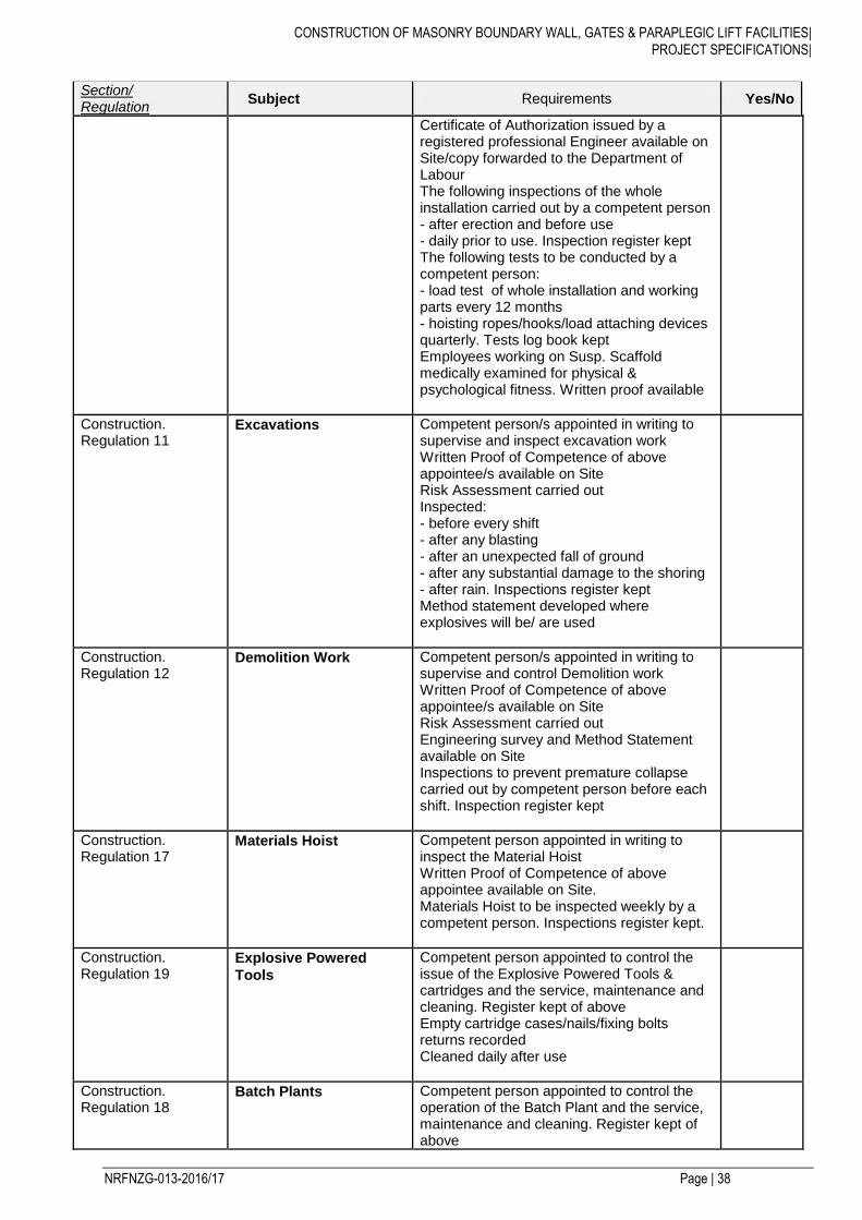
CONSTRUCTION OF MASONRY BOUNDARY WALL, GATES & PARAPLEGIC LIFT FACILITIES|
PROJECT SPECIFICATIONS|
NRFNZG-013-2016/17 Page | 38
Section/ Regulation
Subject Requirements Yes/No
Certificate of Authorization issued by a registered professional Engineer available on Site/copy forwarded to the Department of Labour The following inspections of the whole installation carried out by a competent person - after erection and before use - daily prior to use. Inspection register kept The following tests to be conducted by a competent person: - load test of whole installation and working parts every 12 months - hoisting ropes/hooks/load attaching devices quarterly. Tests log book kept Employees working on Susp. Scaffold medically examined for physical & psychological fitness. Written proof available
Construction. Regulation 11
Excavations Competent person/s appointed in writing to supervise and inspect excavation work Written Proof of Competence of above appointee/s available on Site Risk Assessment carried out Inspected: - before every shift - after any blasting - after an unexpected fall of ground - after any substantial damage to the shoring - after rain. Inspections register kept Method statement developed where explosives will be/ are used
Construction. Regulation 12
Demolition Work Competent person/s appointed in writing to supervise and control Demolition work Written Proof of Competence of above appointee/s available on Site Risk Assessment carried out Engineering survey and Method Statement available on Site Inspections to prevent premature collapse carried out by competent person before each shift. Inspection register kept
Construction. Regulation 17
Materials Hoist Competent person appointed in writing to inspect the Material Hoist Written Proof of Competence of above appointee available on Site. Materials Hoist to be inspected weekly by a competent person. Inspections register kept.
Construction. Regulation 19
Explosive Powered
Tools
Competent person appointed to control the issue of the Explosive Powered Tools & cartridges and the service, maintenance and cleaning. Register kept of above Empty cartridge cases/nails/fixing bolts returns recorded Cleaned daily after use
Construction. Regulation 18
Batch Plants Competent person appointed to control the operation of the Batch Plant and the service, maintenance and cleaning. Register kept of above
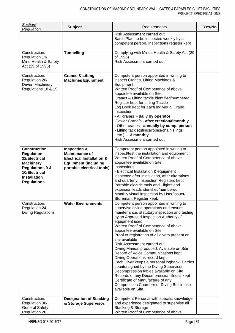
CONSTRUCTION OF MASONRY BOUNDARY WALL, GATES & PARAPLEGIC LIFT FACILITIES|
PROJECT SPECIFICATIONS|
NRFNZG-013-2016/17 Page | 39
Section/ Regulation
Subject Requirements Yes/No
Risk Assessment carried out Batch Plant to be inspected weekly by a competent person. Inspections register kept
Construction. Regulation 13/ Mine Health & Safety Act (29 of 1996)
Tunnelling Complying with Mines Health & Safety Act (29 of 1996) Risk Assessment carried out
Construction. Regulation 20/ Driven Machinery Regulations 18 & 19
Cranes & Lifting
Machines Equipment
Competent person appointed in writing to inspect Cranes, Lifting Machines & Equipment Written Proof of Competence of above appointee available on Site. Cranes & Lifting tackle identified/numbered Register kept for Lifting Tackle Log Book kept for each individual Crane Inspection:
- All cranes - daily by operator
-Tower Crane/s - after erection/6monthly
- Other cranes - annually by comp. person - Lifting tackle(slings/ropes/chain slings
etc.) - 3 monthly Risk Assessment carried out
Construction.
Regulation
22/Electrical
Machinery
Regulations 9 &
10/Electrical
Installation
Regulations
Inspection &
Maintenance of
Electrical Installation &
Equipment (including
portable electrical tools)
Competent person appointed in writing to inspect/test the installation and equipment. Written Proof of Competence of above appointee available on Site. Inspections: - Electrical Installation & equipment inspected after installation, after alterations and quarterly. Inspection Registers kept Portable electric tools and -lights and extension leads identified/numbered. Monthly visual inspection by User/Issuer/ Storeman. Register kept.
Construction. Regulation 24 Diving Regulations
Water Environments Competent person appointed in writing to supervise diving operations and ensure maintenance, statutory inspection and testing by an Approved Inspection Authority of equipment used Written Proof of Competence of above appointee available on Site Proof of registration of all divers present on site available Risk Assessment carried out Diving Manual produced. Available on Site Record of Voice Communications kept Diving Operations record kept Each Diver keeps a personal logbook. Entries countersigned by the Diving Supervisor Decompression tables available on Site Records of any Decompression illness kept Certificate of Manufacture of any Compression Chamber or Diving Bell in use available on Site
Construction. Regulation 30/ General Safety Regulation 26
Designation of Stacking
& Storage Supervisor.
Competent Person/s with specific knowledge and experience designated to supervise all Stacking & Storage Written Proof of Competence of above
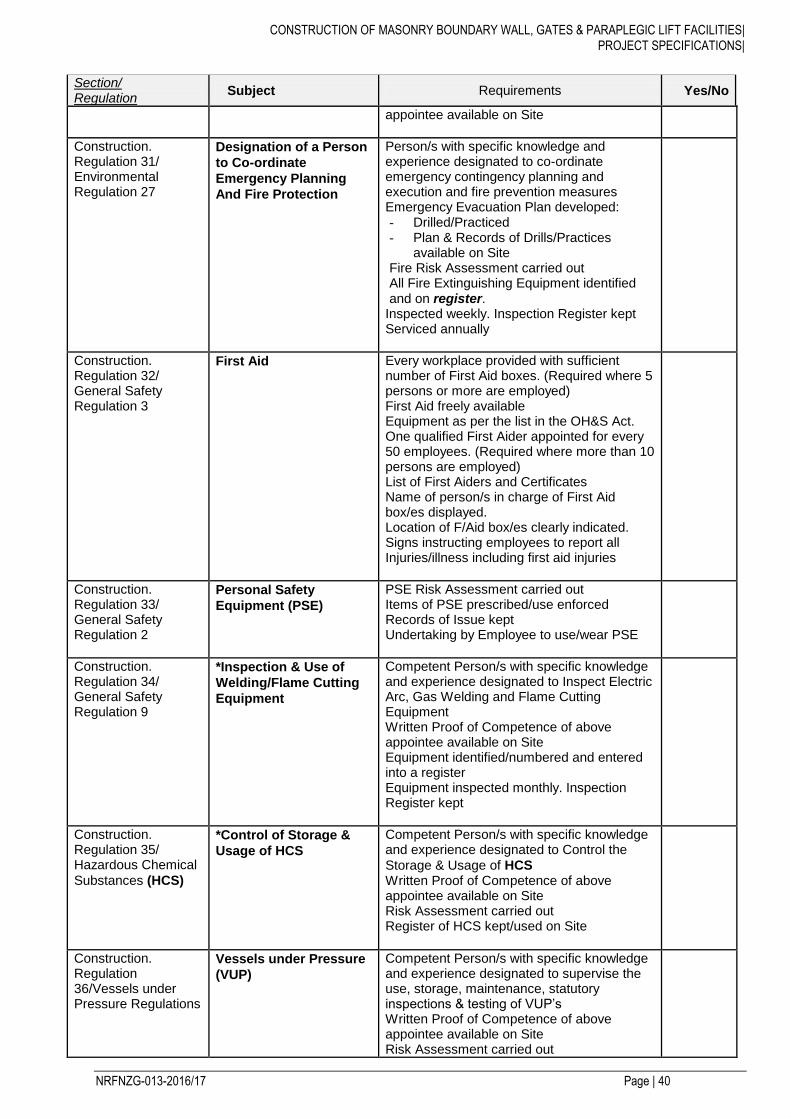
CONSTRUCTION OF MASONRY BOUNDARY WALL, GATES & PARAPLEGIC LIFT FACILITIES|
PROJECT SPECIFICATIONS|
NRFNZG-013-2016/17 Page | 40
Section/ Regulation
Subject Requirements Yes/No
appointee available on Site
Construction. Regulation 31/ Environmental Regulation 27
Designation of a Person
to Co-ordinate
Emergency Planning
And Fire Protection
Person/s with specific knowledge and experience designated to co-ordinate emergency contingency planning and execution and fire prevention measures Emergency Evacuation Plan developed: - Drilled/Practiced - Plan & Records of Drills/Practices
available on Site Fire Risk Assessment carried out All Fire Extinguishing Equipment identified and on register.
Inspected weekly. Inspection Register kept Serviced annually
Construction. Regulation 32/ General Safety Regulation 3
First Aid Every workplace provided with sufficient number of First Aid boxes. (Required where 5 persons or more are employed) First Aid freely available Equipment as per the list in the OH&S Act. One qualified First Aider appointed for every 50 employees. (Required where more than 10 persons are employed) List of First Aiders and Certificates Name of person/s in charge of First Aid box/es displayed. Location of F/Aid box/es clearly indicated. Signs instructing employees to report all Injuries/illness including first aid injuries
Construction. Regulation 33/ General Safety Regulation 2
Personal Safety
Equipment (PSE)
PSE Risk Assessment carried out Items of PSE prescribed/use enforced Records of Issue kept Undertaking by Employee to use/wear PSE
Construction. Regulation 34/ General Safety Regulation 9
*Inspection & Use of
Welding/Flame Cutting
Equipment
Competent Person/s with specific knowledge and experience designated to Inspect Electric Arc, Gas Welding and Flame Cutting Equipment Written Proof of Competence of above appointee available on Site Equipment identified/numbered and entered into a register Equipment inspected monthly. Inspection Register kept
Construction. Regulation 35/ Hazardous Chemical
Substances (HCS)
*Control of Storage &
Usage of HCS
Competent Person/s with specific knowledge and experience designated to Control the
Storage & Usage of HCS Written Proof of Competence of above appointee available on Site Risk Assessment carried out Register of HCS kept/used on Site
Construction. Regulation 36/Vessels under Pressure Regulations
Vessels under Pressure
(VUP)
Competent Person/s with specific knowledge and experience designated to supervise the use, storage, maintenance, statutory inspections & testing of VUP’s Written Proof of Competence of above appointee available on Site Risk Assessment carried out

CONSTRUCTION OF MASONRY BOUNDARY WALL, GATES & PARAPLEGIC LIFT FACILITIES|
PROJECT SPECIFICATIONS|
NRFNZG-013-2016/17 Page | 41
Section/ Regulation
Subject Requirements Yes/No
Certificates of Manufacture available on Site Register of VUP’s on Site Inspections & Testing by Approved Inspection Authority (AIA): - after installation/re-erection or repairs - every 36 months. - Register/Log kept of inspections, tests.
Modifications & repair
Construction. Regulation 37
Construction Vehicles &
Earth Moving
Equipment
Operators/Drivers appointed to: - Carry out a daily inspection prior to use - Drive the vehicle/plant that he/she is
competent to operate/drive Written Proof of Competence of above appointee available on Site Record of Daily inspections kept
Construction. Regulation 38/ General Safety Regulation 13D
Inspection of Ladders Competent person appointed in writing to inspect Ladders Ladders inspected at arrival on site and monthly there after. Inspections register kept
Construction. Regulation 39/ General Safety regulation 13B
Ramps Competent person appointed in writing to Supervise the erection & inspection of Ramps. Inspection register kept.
© Copyright 2016
PART D: ENVIRONMENTAL MANAGEMENT PLAN
D MANAGEMENT OF CONTRACTOR ACTIVITIES DURING THE CONSTRUCTION PHASE
D1 Overall Purpose of this EMP
In order to ensure a holistic approach to the management of environmental impacts during the construction
of this project, this document sets out the environmental specifications which will be applicable to the
construction phase of the project.
This Environmental Management Plan (EMP) outlines the environmental specifications which will be
required to be implemented and adhered to by the construction teams. The EMP has as its basis general
mitigation measures for implementation on site. However, where necessary, these measures have been
expanded upon and additional issues have been addressed in order to ensure that all environmental
aspects are appropriately considered and monitored.
This draft EMP will be amended to comply with the environmental authorisation, if issued for a specific
contract. It should be borne in mind that the EMP is a dynamic document, which can be updated when
required.
D2 Objectives of the EMP
The EMP has the following objectives:
To state the standards and guidelines which the Contractor will be required to adhere to in terms of
environmental legislation;
To set out the mitigation measures and environmental specifications which the Contractor will be
required to implement for the construction phase of the project in order to minimise the extent of
environmental impacts, and where possible to improve the condition of the environment;
To provide guidance regarding the method statements which the Contractor will be required to
compile and implement to achieve the environmental specifications;
To define corrective actions which the Contractor must take in the event of non-compliance with the
specifications of this EMP;
To prevent long-term or permanent environmental degradation.
D3 Implementation and Operation
a. Roles and Responsibilities
NZGSA is the applicant for the approval of all Environmental Impact Assessment on the NZGSA
Construction of Masonry Boundary Wall, Gates & Paraplegic Lift Facilities Project. Peak Consulting will
therefore, be the entity monitoring the implementation of the EMP. The successful bidder will, in terms of the
tender documentation, be responsible to implement the proposed mitigation measures in this EMP on
NZGSA behalf.
CONSTRUCTION OF MASONRY BOUNDARY WALL, GATES & PARAPLEGIC LIFT FACILITIES|
PROJECT SPECIFICATIONS|
NRFNZG-013-2016/17 Page | 43
b. NZGSA’s Environmental Representative
NZGSA’ Environmental Representative, will be responsible for overseeing the overall implementation of the
EMP in accordance with the requirements of the Contract and the environmental authorisation.
c. Site Environmental Control Officer (SECO)
The Contractor shall be responsible for the appointment of a Site Environmental Control Officer (SECO) for
the duration of the contract.
The Site Environmental Control Officer will oversee the construction phases of the project and will ensure
that all environmental specifications and EMP requirements are met at all times. The SECO will report to the
Engineer in an advising capacity.
The SECO will be responsible for monitoring, reviewing and verifying the Contractor’s compliance with the
EMP. The SECO’s duties in this regard will include, inter alia, the following:
Ensuring that all the environmental authorisations and permits required in terms of the applicable
legislation have been obtained prior to construction commencing;
Monitoring and verifying that the EMP and environmental authorisation are adhered to at all times
and taking action if specifications are not followed;
Monitoring and verifying that environmental impacts are kept to a minimum;
Assisting the Contractor in finding environmentally responsible solutions to problems;
Keeping accurate and detailed records of all activities on site;
Inspecting the site and surrounding areas on a regular basis with regard to compliance with the
EMP and environmental authorisation;
Monitoring the Contractor’s requirement to provide environmental awareness training for all new
personnel on site;
Ensuring that activities on site comply with all relevant environmental legislation;
Advising the Engineer on any non-compliance with regard to EMP.
Undertaking a continual internal review of the EMP and submitting any changes to NZGSA and
NZGSA for review and approval;
Keeping a register of complaints on site and recording community comments and issues, and the
actions taken in response to these complaints.
The SECO must have:
A good working knowledge of all the relevant environmental policies, legislation, guidelines and
standards;
The ability to conduct inspections and to produce thorough, readable and informative reports;
The ability to manage public communication and complaints, if directed to do so by the Engineer;
The ability to think holistically about the structure, functioning and performance of environmental
systems;
Proven competence in the application of the following integrated environmental management tools:
CONSTRUCTION OF MASONRY BOUNDARY WALL, GATES & PARAPLEGIC LIFT FACILITIES|
PROJECT SPECIFICATIONS|
NRFNZG-013-2016/17 Page | 44
o EIA;
o EMPs;
o Environmental auditing;
o Mitigation and optimisation of impacts;
o Monitoring and evaluation of impacts;
o Environmental Management Systems (EMS).
The SECO must be fully conversant with the EIA and EMP for the proposed project and all relevant
environmental legislation. The NZGSA shall have the authority to instruct the Contractor to replace the
SECO if, in their opinion, the appointed person is not fulfilling his/her duties in terms of the requirements of
the EMP.
Such instruction will be in writing and will clearly set out the reasons why a replacement is required and the
timeframe for such replacement.
d. External Environmental Auditor
An external environmental auditor will be appointed by NZGSA to ensure Contractor compliance to the
EMP. NZGSA and the external auditor will jointly determine the intervals at which environmental audits
should be undertaken. The environmental audit programme should at least include the following:
Comprehensive environmental audits to be undertaken periodically (at least every quarter) during
the construction phase, to verify compliance with the EMP, environmental authorisation and
construction contract, and all applicable environmental legislation. An audit report should contain
recommendations on environmental management activities which need to be implemented. The
external auditor will report concurrently to NZGSA;
A comprehensive environmental audit to be undertaken at the completion of the construction phase,
to verify compliance with the EMP and all applicable environmental legislation. An audit report
should contain recommendations on environmental management activities which need to be
implemented within the maintenance phase. The external auditor will report concurrently to NZGSA.
D4 Special conditions
The Sub-Contractor shall strictly comply with the requirements of Annexure VII of the Concession Contract
in relation to the Environmental Requirements.
The Sub-Contractor shall strictly comply with the criteria as set out in the Record of Decision for the project
as well as this Environmental Management Plan (EMP).
The Sub-Contractor shall be responsible for obtaining all necessary environmental Permits and
Authorizations for the Sub-Contract Works including Permits and Authorizations required pursuant to
National and Provincial laws and Regulations and local authority by-laws. The Sub-Contractor shall note that
NZGSA Platinum Concession (Pty) Ltd would only be responsible for obtaining the above if a specific
agreement was reached with the Sub-Contractor.

CONSTRUCTION OF MASONRY BOUNDARY WALL, GATES & PARAPLEGIC LIFT FACILITIES|
PROJECT SPECIFICATIONS|
NRFNZG-013-2016/17 Page | 45
Where the Contractor has obtained the statutory required Permits and Authorizations, the Sub-Contractor
shall take note and implement any condition or requirement specified in such Permits or Authorizations, over
and above the requirements of this EMP.
For all materials used by the Sub-Contractor during the execution of his work that are sourced from a
commercial process or activity that requires Environmental Permits or Authorizations, a copy of the relevant
Permit or Authorization should be obtained from the commercial source and should be forwarded to NZGSA
Platinum Concessions (Pty) Ltd.
The Sub-Contractor shall at all times and in accordance with NZGSA Environmental Representative
instructions, conduct his activities and those of his employees, in an environmentally sound and acceptable
manner. It is the Sub-Contractor’s responsibility to agree on the environmental condition of any site that the
Sub-Contractor occupies or utilises, in the course of his Sub-Contract Works, with NZGSA Platinum
Concessions (Pty) Ltd’s Environmental Representative. The responsibility for all environmental degrading
activities and incidents shall vest with the Sub-Contractor.
NZGSA, together with the Sub-Contractor, shall carry out regular environmental inspections of the areas
under the Sub-Contractor’s care. If following inspection, any failure or pollution of the environment relating
to acts of the Sub-Contractor, his employees or associated plant and equipment, is identified during this
inspection, the Sub-Contractor shall be instructed in writing to undertake proper mitigation measures and
rehabilitation. If the Sub-Contractor fails to comply with such written instruction within 7 (seven) days of
receipt, NZGSA shall immediately remedy such failure or pollution at the cost of the Sub-Contractor.
Any serious environmental pollution or disaster, such as, but not limited to pollution of ground water, surface
water, sensitive ecological areas or declared heritage sites, shall entitle NZGSA to act immediately to
mitigate such pollution or disaster, using whatever experts that may be required. All costs associated with
such action will be recovered from the Sub-Contractor.
The Sub-Contractor is required to certify that the works and sites utilised in the course of the sub-contract
Works has been maintained and rehabilitated in an environmentally sensitive manner.
The Sub-Contractor shall, prior to the release of the final retention monies, submit such certification to
NZGSA Platinum Concessions, confirming environmental compliance. A separate letter will also be
submitted indemnifying NZGSA from any latent environmental defect or environmental pollution that may
occur in consequence of the Sub-Contractor’s actions or works
If the Sub-Contract work’s value is more than Ten Million Rand, the environmental certification submitted
prior to final retention release shall be obtained from an independent environmental consultant/practitioner
whose services shall be for the cost of the Sub-Contractor.
D5 Management and Mitigation plans
The management all negative environmental impacts caused by the Contractor appointed during the
construction phase are dealt with through specific management and mitigation plans. Each environmental
component that requires management and mitigation has been identified.
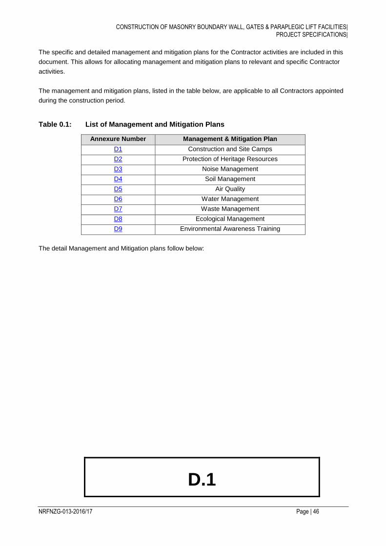
CONSTRUCTION OF MASONRY BOUNDARY WALL, GATES & PARAPLEGIC LIFT FACILITIES|
PROJECT SPECIFICATIONS|
NRFNZG-013-2016/17 Page | 46
The specific and detailed management and mitigation plans for the Contractor activities are included in this
document. This allows for allocating management and mitigation plans to relevant and specific Contractor
activities.
The management and mitigation plans, listed in the table below, are applicable to all Contractors appointed
during the construction period.
Table 0.1: List of Management and Mitigation Plans
Annexure Number Management & Mitigation Plan
D1 Construction and Site Camps
D2 Protection of Heritage Resources
D3 Noise Management
D4 Soil Management
D5 Air Quality
D6 Water Management
D7 Waste Management
D8 Ecological Management
D9 Environmental Awareness Training
The detail Management and Mitigation plans follow below:
D.1
CONSTRUCTION OF MASONRY BOUNDARY WALL, GATES & PARAPLEGIC LIFT FACILITIES|
PROJECT SPECIFICATIONS|
NRFNZG-013-2016/17 Page | 47
Construction and Site Camps
Management and Mitigation Plan
© Copyright 2016
D.1 : CONSTRUCTION AND SITE CAMPS
1. PURPOSE
To minimize impacts by the Contractor associated with the establishment and operation of construction and
site camps and workshops.
2. COMPONENTS
The plan is made up of the following components:
a. Location of Construction Camps
b. Construction Camp Restrictions and Restraints
c. Ablution Facilities
d. Heating and Cooking Facilities
e. Water for Human Consumption
f. Eating Areas
g. Fencing and No-Go Areas
h. Fires
i. Workshops.
a. Location of Construction and Camp Sites
Objectives To ensure that the Contractor establish his construction camps, offices, workshops, staff accommodation
and testing facilities on the site in a manner that does not adversely affect the environment.
Targets Compliance to all statutory, RoD and permit requirements.
Minimise complaints received regarding the construction camps.
Methods Statements The Construction and Camp sites shall be established within the road reserve.
If Construction and Camp sites are located outside of the road reserve the necessary landowner
approval shall be obtained and provided to NZGSA.
The Contractor shall produce a site plan showing the site layout, including the positions of all buildings,
vehicle wash areas, fuel storage areas, access roads and other infrastructure prior to establishment of
the site for approval by NZGSA.
Only designated areas, as indicated on the layout plan shall be used for the storage of materials,
machinery, and equipment, and for site offices and accommodation facilities.
The site offices and accommodation units shall not be sited in close proximity to steep areas, as this will
increase the potential for soil erosion.
If the site traverses watercourses, streams and rivers, the offices (and in particular the ablution
facilities, aggregate stockpiles, spoil areas and hazardous material stockpiles) shall be located as far
away as possible from any watercourse, and downstream of water bodies.
The Contractor shall establish these facilities in accordance with the design criteria and approved layout
plan and in a manner that does not adversely affect the environment. Camps, offices, workshops, staff
accommodation and testing facilities shall be maintained in an orderly and tidy condition.
Throughout the period of construction, the Contractor shall restrict all activities to within the designated
areas as indicated on the approved layout plan.
CONSTRUCTION OF MASONRY BOUNDARY WALL, GATES & PARAPLEGIC LIFT FACILITIES|
PROJECT SPECIFICATIONS|
NRFNZG-013-2016/17 Page | 49
Detailed colour photographs shall be taken by the Contractor of the proposed sites before any clearing
commences. These records shall be kept for consultation during rehabilitation of the site.
The placement of buildings and equipment shall be done to minimise the footprint and visual impact of
the sites – where applicable the roofing cladding type and colour will be selected to minimise reflection
as this could increase the visual impact.
Large indigenous trees within the confines of the site if any that can be retained shall be adequately
protected and indicated on the construction layout plans.
Demarcation of the site, vegetation and topsoil removal shall occur prior to any other construction
activities commencing on site.
The Construction and Camp sites shall be neat and acceptable to the travelling motorist passing these
areas next to the road – specifically when tents are utilised.
b. Construction Camp Restrictions and Restraints
Objectives
Specify restrictions to be adhered to at all Construction and Camp sites.
Targets
Compliance to all statutory, RoD and permit requirements.
Minimise complaints received regarding the Construction and Camp sites.
Method Statements
The following actions shall be prohibited:
The use of rivers and streams for washing of clothes and kitchen utensils;
The use of welding equipment, oxy-acetylene torches and other bare flames where fires constitute a
hazard;
Indiscriminate disposal of rubbish or construction wastes or rubble;
Littering of the site;
Poaching of any description;
Latrining outside of the designated facilities;
Burning of wastes and/or cleared vegetation;
c. Ablution Facilities
Objectives
To make provision for adequate and sufficient ablution facilities during the contract period.
Targets
Compliance to all statutory, RoD and permit requirements.
Minimise complaints received regarding the Construction and Camp sites.
Method Statements
CONSTRUCTION OF MASONRY BOUNDARY WALL, GATES & PARAPLEGIC LIFT FACILITIES|
PROJECT SPECIFICATIONS|
NRFNZG-013-2016/17 Page | 50
The Contractor shall provide suitable sanitary arrangements at Construction and Camp sites and along
the work site for its employees. These facilities must be easily accessible (within 500m from any point of
work).
Toilets shall be provided at the preferred ratio of 1 toilet per 15 workers.
Performing ablutions outside the toilet facilities is strictly prohibited and the use of the veld for this
purpose shall not, under any circumstances, be allowed.
The toilets shall be secured and provided with an external closing mechanism to prevent toilet paper
from being blown out.
Toilets will not be placed in areas susceptible to standing or flowing water and will be sited away from
any identified environmentally sensitive areas.
The Contractor shall ensure that the entrances to toilets are adequately screened from public view.
Toilets will be secured in order to prevent them from blowing over.
Only approved chemical toilets will be used and will be emptied on a regular basis.
The Contractors shall ensure that there is no spillage when the chemical toilets are cleaned or during
normal operation and that the contents are properly removed from site.
d. Heating and Cooking Facilities
Objectives
To make provision for cooking and heating needs during the contract period.
Targets
Compliance to all statutory, RoD and permit requirements.
Minimise complaints received regarding the Construction and Camp sites.
Method Statements
The Contractor shall provide adequate cooking facilities for its staff, so that they are not encouraged to
supplement their comforts on site by accessing what can be taken from the natural surroundings.
The Contractor shall ensure that energy sources are available at all times for construction activities, and
supervision and security personnel, for heating and cooking purposes.
e. Water for Human Consumption
Objectives
To ensure that a potable and sufficient water source is supplied for all Construction and Camp sites.
Targets
Compliance to all statutory, RoD and permit requirements.
Minimise complaints received regarding the Construction and Camp sites.
Method Statements
Water for human consumption shall be available at all Construction and Camp sites.
f. Eating Areas
Objectives
CONSTRUCTION OF MASONRY BOUNDARY WALL, GATES & PARAPLEGIC LIFT FACILITIES|
PROJECT SPECIFICATIONS|
NRFNZG-013-2016/17 Page | 51
To ensure that designated eating areas are supplied for all Construction and Camp sites.
Targets
Compliance to all statutory, RoD and permit requirements.
Minimise complaints received regarding the Construction and Camp sites.
Method Statements
The Contractor shall provide designated eating areas for its employees.
The Contractor shall provide the necessary bins at these areas and the bins will be emptied on a daily
basis. The collected waste will be stored in a central waste area to ensure ease of removal.
g. Fencing and No-Go Areas
Objectives
To ensure that all sites are adequately fenced and that No-Go areas are clearly demarcated.
Targets
Compliance to all statutory, RoD and permit requirements.
Minimise complaints received regarding the Construction and Camp sites.
Method Statements
The Contractor shall make provision for appropriate fencing to be erected along the perimeter of
construction areas, where appropriate. No-go areas will also be demarcated by fencing to ensure that
personnel, machinery, equipment or material do not impact these areas.
No activities shall take place beyond the demarcated areas. Fences shall be erected according to an
agreed sequence and time programme, and co-ordinated with the arrival of equipment, staff and
materials onto site.
The fencing will not be moved or removed, at any stage of the project. The Contractor shall ensure that
any fencing damaged during construction activities shall be replaced immediately and at their expense.
h. Fires
Objectives
To ensure that fires are adequately controlled during the construction period.
Targets
Compliance to all statutory, RoD and permit requirements.
Minimise complaints received regarding the Construction and Camp sites.
Method Statements
The Contractor shall take all reasonable steps to avoid any fires.
Open fires shall only be permitted at Construction and Camp sites in facilities or equipment specially
constructed for this purpose.
Prior to the commencement of construction activities the Contractor shall ascertain the fire requirements
of the local council and must develop a contingency plan in case of a fire.
CONSTRUCTION OF MASONRY BOUNDARY WALL, GATES & PARAPLEGIC LIFT FACILITIES|
PROJECT SPECIFICATIONS|
NRFNZG-013-2016/17 Page | 52
The Contractor shall ensure that there is basic fire-fighting equipment on site at all times. This
equipment shall include fire extinguishers and beaters.
The Contractor shall pay any costs incurred by organisations called to put out fires started by any
employee of the Contractor or any Sub-Contractor.
The Contractor shall pay the costs incurred to reinstate burnt areas as deemed necessary.
The Contractor shall take all reasonable steps to extinguish any fires where other individuals may have
started a fire, either intentionally or unintentionally.
i. Workshops
Objectives
To ensure that the Contractor establish his workshops on the site in a manner that does not adversely affect
the environment.
Targets
Compliance to all statutory, RoD and permit requirements.
Minimise complaints received regarding workshops.
Method Statements
All the necessary handling and safety equipment required for the safe use of petrochemicals and oils
shall be provided by the Contractor to, and used or worn by the staff whose duty it is to manage and
maintain the supplier’s plant, machinery and equipment.
Petrochemicals, oils and identified hazardous substances shall only be stored under controlled
conditions. All hazardous materials will be stored in a secured, appointed area that is fenced and has
restricted entry. Storage of bituminous products shall only take place using suitable containers.
The Contractor shall provide proof to the Engineer that relevant authorisation to store such substances
has been obtained from the relevant authority.
An adequate bund wall (110% volume) shall be provided for fuel and diesel areas to accommodate any
spillage or overflow of these substances. The area inside the bund wall should be lined with an
impervious lining to prevent infiltration of the fuel into the soil. The bunding shall be undertaken as per
the requirements of SABS 089:1999 Part 1.
Fuel tanks shall be located at least 3.5m from buildings boundaries and any other combustible or
flammable material.
The Contractor will ensure that an emergency preparedness plan is in place for implementation in case
of leakage or spillage of fuel which can be harmful to an individual or the receiving environment.
Suitable and adequate supplies of absorbents shall be available at all times to control and absorb any
spillages.
Used oil, lubricants and cleaning materials from the maintenance of vehicles and machinery shall be
collected in a holding tank and recycled.
Water generated inside the workshop shall pass through an oil trap to separate the water and oil. Oils
collected in this manner, shall be retained in a safe holding tank and recycled.
Oil collected by a mobile servicing unit shall be stored in the service unit’s sludge tank and discharged
into the safe holding tank for recycling.
All used filter materials shall be stored in a secure bin for disposal as hazardous waste.
CONSTRUCTION OF MASONRY BOUNDARY WALL, GATES & PARAPLEGIC LIFT FACILITIES|
PROJECT SPECIFICATIONS|
NRFNZG-013-2016/17 Page | 53
D.2 Protection of Heritage Resources
Management and Mitigation Plan
© Copyright 2016
D.2 : PROTECTION OF HERITAGE RESOURCES
(i)
b. 1. PURPOSE
The purpose of the heritage resources management and mitigation plan is to ensure that heritage sites,
structures older than 60 years, and archaeological or paleontological sites, either inside or in close proximity
of the road reserve, that are protected through law, are identified and any potential negative impacts on
these sites avoided or mitigated.
c. 2. COMPONENTS
The plan is made up of the following components:
a. Protected heritage resources
b. Chance heritage finds
3. MANAGEMENT AND MITIGATION
a. Protected heritage resources
Objectives To identify and document in detail the remains of man-made structures uncovered before construction activities are initiated on-site. Targets Identify all protected heritage resources as defined in the National Heritage Resources Act (1999)
before construction is initiated.
Document in detail all identified protected heritage resources as defined in the National Heritage
Resources Act (1999).
All construction works close to all identified heritage resources would have to be carried out under the
frequent on-site supervision of competent heritage practitioners, and if required by the South African
Heritage Resources Agency (SAHRA). A representative from SAHRA must also be a part of the
supervision team – SAHRA will have to ensure that this representative is available as and when
required as per the construction program.
Method Statements
Should any archaeological, paleontological, historic or cultural resource sites (including graves) be
unexpectedly uncovered during construction, operation or maintenance work in the area, all work shall
cease and a specialist should be consulted regarding remedial action and whether a permit is required
in terms of the National Heritage Resources Act (No 25 of 1999).
Under no circumstances shall artefacts or relics of historic value be removed, destroyed or interfered
with by Contractors and their employees.
Graves and other heritage sites within the road reserve should be fenced.
b. Chance Heritage Finds
Objectives
To effectively manage the discovery of chance heritage finds and the disturbance thereof and how to
address same during the course of construction.
CONSTRUCTION OF MASONRY BOUNDARY WALL, GATES & PARAPLEGIC LIFT FACILITIES|
PROJECT SPECIFICATIONS|
NRFNZG-013-2016/17 Page | 55
Targets
Compliance to all statutory, RoD and permit requirements.
Any structure, object, remain(s) or deposit(s) that is of demonstrable or suspected to be of an
archaeological or historical nature whether in situ or not, shall be reported to the relevant Authorities.
Reporting of any chance heritage find shall be done within 24 hours of its discovery.
Method Statements
Employees and sub Contractors shall receive training regarding chance heritage finds.
All construction works shall be carried out with sensitivity to the possible unearthing of heritage
materials or objects, artefacts or graves.
In the event of the discovery of heritage materials or objects, artefacts or graves, relevant activities in
the specific area of the find shall cease pending further investigation.
Nothing may be moved or removed from site and the Contractor shall immediately notify a heritage
practitioner to consult with SAHRA.
A Heritage Practitioner is to assess the site to establish its status and to categorise it as either:
o (A): Heritage sites, structures older than 60 years and archaeological or paleontological sites or
o (B): Grave(s) or human remains.
CONSTRUCTION OF MASONRY BOUNDARY WALL, GATES & PARAPLEGIC LIFT FACILITIES|
PROJECT SPECIFICATIONS|
NRFNZG-013-2016/17 Page | 56
D.3 Noise Management
Management and Mitigation Plan
© Copyright 2016
D.3 : NOISE MANAGEMENT
(ii)
1. PURPOSE
To ensure that noise and vibration from construction activities do not exceed the relevant limits or result in a
nuisance disturbance.
d. 2. COMPONENTS
The plan is made up of the following components:
a. General noise mitigation
b. Road Construction Activities and Equipment
c. Blasting and Vibration
3. MANAGEMENT AND MITIGATION
Noise sensitive areas include: Outdoor – parks; historic sites; amphitheatres; recreation areas;
playgrounds; cemeteries; (Residences – single & multifamily residences (apartment buildings, simplex and
duplex housing complexes) and retirement homes); offices indoor – places of worship; educational
activities; crèches; hospitals/hospices; concert halls / auditoriums / theatres; libraries;
recording/broadcasting studios; museums; hotels/B&B establishments, during hours of operation.
a. General noise mitigation
Objectives
To ensure that noise from general construction activities does not result in exceedances of relevant limits
and /or result in a nuisance disturbance.
Targets
Compliance to all statutory, RoD and permit requirements.
Compliance to SANS 10103:2004
Method Statements
Liaise with local residents how to best minimise construction noise impacts in the vicinity of noise
sensitive areas, where there is a probability of high noise levels being generated.
Local residents shall be kept informed of the nature and duration of intended activities prior to
commencement and kept updated as to changes in the schedule or management and mitigation plan as
the work progresses.
Site offices and equipment compounds shall be sited away from residences where possible.
Hoardings and/or other noise barriers shall be erected around critical work areas to act as acoustical
barriers and minimise noise emissions to the surrounding areas.
Enclose especially noisy activities if above noise limits.
Transportable noise screens shall be placed between noise sources and noise sensitive areas for the
duration of specific noisy construction activities e.g. between a compressor unit and an educational
facility.
Where possible, noisy activities shall be scheduled to occur at the same time, so as to minimise the
total duration of the noise impacts.
Less noisy construction methods and technology shall be favoured on site with the aim of minimising
the total noise impact severity.
CONSTRUCTION OF MASONRY BOUNDARY WALL, GATES & PARAPLEGIC LIFT FACILITIES|
PROJECT SPECIFICATIONS|
NRFNZG-013-2016/17 Page | 58
Noisy fixed facilities shall be located well away from noise sensitive areas.
In cases where noisy activities and equipment (such as piling, cranes, compressors, demolition,
blasting, and implosions,) create unacceptable noise impacts at the closest sensitive receiver, noise
protection at the receiver shall be implemented.
b. Road Construction Activities and Equipment
Objectives
To ensure that noise from road construction activities and equipment does not result in the exceeding of
relevant limits and /or result in a nuisance disturbance.
Targets
Compliance to all statutory, RoD and permit requirements.
Compliance to SANS 10103:2004.
Method Statements
Modern low noise emission vehicles and equipment shall be favoured on site. The details of all
construction machinery and vehicles must be determined prior to construction in order to identify
potentially noisy machinery and to seek possible alternatives. These details will include the
manufacturer, type and noise emission data of each machinery/vehicle and how many will be used at
any time along each section of the route. Where this information is not available, noise measurements
must be conducted prior to use of such machinery or vehicles.
All noise-making equipment shall be turned off when not in use.
All equipment shall be kept in good working order.
All equipment shall be operated within specifications and capacity (i.e. do not overload machines). The Contractor shall familiarise himself with, and adhere to, any local bylaws and regulations regarding
the generation of noise.
Heavy vehicles should be routed away from noise sensitive areas wherever possible.
Conform to defined speed limits.
c. Blasting and Vibration
Objectives
To ensure that noise and vibration from blasting does not result in the exceeding of relevant limits and /or
result in a nuisance disturbance.
Targets
Compliance to all statutory, RoD and permit requirements.
Compliance to SANS 10103:2004.
Method Statements
All blasting shall be undertaken under strict supervision of a registered specialist blaster.
The size of explosive charges used for blasting shall be optimised so as to balance breaking capability
against minimising any vibration impact and fly rock.
No damage to neighbouring properties shall be allowed – detailed incident records shall be kept for
reference purposes.

CONSTRUCTION OF MASONRY BOUNDARY WALL, GATES & PARAPLEGIC LIFT FACILITIES|
PROJECT SPECIFICATIONS|
NRFNZG-013-2016/17 Page | 59
Pre-blast photographic records of neighbouring buildings shall be prepared where these are in close
proximity of blasting activities.
Peak Particle Velocity at residential buildings shall not exceed 25mm/s.
Peak Particle Velocity at reinforced Concrete Structures shall not exceed 51mm/s.
Peak Particle Velocity near Eskom power lines shall meet the Eskom specifications.
© Copyright 2016
D.4 Soil Management
Management and Mitigation Plan
© Copyright 2016
D.4 : SOIL MANAGEMENT
1. PURPOSE
The purpose of the soil management plan is to ensure that all topsoil stripping, stockpiling and replacement
operations and spoil management will be undertaken in a manner that limits impacts emanating from the
operations on the surrounding communities and natural environment.
2. COMPONENTS
The plan is made up of the following components:
a. Topsoil storage
b. Spoil material
c. Borrow pits and quarries.
3. MANAGEMENT AND MITIGATION
Topsoil is considered to be the natural soil covering and shall include all organic matter. Depth may vary at
each site, and must be determined on a site-specific basis and removed accordingly. The areas to be
cleared of topsoil shall include the storage areas and site camps.
a. Topsoil storage
Objectives
To ensure that wherever topsoil is present that it is removed and conserved for re-use.
Targets
>95% of recovered topsoil to be re-used.
Method Statements
Strip topsoil to the required depth at all sites before any construction activities commence.
All topsoil stripping, stockpiling and replacement operations shall be undertaken in a manner that limits
impacts emanating from the operations on the surrounding communities.
Topsoil stripping and handling in windy or excessively rainy conditions shall be avoided.
Topsoil shall be handled twice only – once to strip and stockpile, and secondly to replace, level, shape
and scarify.
All topsoil stockpiles shall be sufficiently located away from seepage zones, flood lines, water courses
and other ecological sensitive areas.
The topsoil stockpiles will be stored, shaped and sited in such a way that they do not interfere with the
flow of water such that damming or erosion is caused, or the stockpiles themselves are eroded through
the action of water.
Topsoil stockpiles shall not be higher than 2 meters and should stockpiles require to exceed this limit,
measures must be introduced to ensure the employees and/or the public are not at a safety risk.
Topsoil stockpiles shall not have slopes steeper than 1 vertical: 2, 5 horizontal.
Topsoil stockpiles shall be utilised in rehabilitation efforts as soon as possible and will preferably not be
stockpiled for longer than 6 months.
Topsoil stockpiles older than 6 months may need to be enriched or upgraded with fertiliser prior to
replacement to ensure its effectiveness as topsoil.
Topsoil stockpiles shall be protected with appropriate soil conservation measures from wind and water
erosion.
No vehicles shall be allowed on the topsoil stockpiles.
CONSTRUCTION OF MASONRY BOUNDARY WALL, GATES & PARAPLEGIC LIFT FACILITIES|
PROJECT SPECIFICATIONS|
NRFNZG-013-2016/17 Page | 62
The stockpiles shall not be allowed to become contaminated with oil, diesel, petrol, waste or any other
material, which may later inhibit the growth of vegetation.
Topsoil stripped from different soil zones shall be stockpiled separately and be clearly distinguishable.
Topsoil stockpiles will be cleared of any alien vegetation by means of appropriate methods.
Topsoil shall not be compacted in any way, nor shall any object or material be placed or stockpiled on it.
The Contractor’s responsibility shall include the clearing of drainage or water systems that may have
been affected by negligence within and beyond the boundaries of the site.
b. Spoil material
Objectives
To ensure proper spoil management during the construction phase.
Targets
Position spoil sites to result in least visual impact.
No evidence of runoff of sediment-laden water from construction sites.
Method Statements
The Contractor shall be responsible for the safe siting, operation, maintenance and closure of any spoil
site used during the contract period. This will include existing spoil sites that are being re-entered.
The affected landowner shall be consulted and must provide written consent for the location of such
spoil sites on his property.
Spoil dumps shall be located away from seepage zones, flood lines, water courses and other
ecologically sensitive areas at least 50 metres above the 1:100 year flood line of streams and rivers.
A photographic record will be kept of all spoil sites for monitoring purposes, and must include
photographs of before the site is used, as well as after re-vegetation.
Spoil dumps shall not have slopes steeper than 1 vertical: 2.5 horizontal.
Final shaping, top soiling and re-vegetation shall be done as soon as possible.
Spoil dumps shall be protected with appropriate soil conservation measures from wind and water
erosion.
Avoid spoil handling and dumping in windy or excessively rainy conditions.
No waste, such as hazardous waste, construction waste, building rubble and domestic waste shall be
allowed on the spoil dumps.
Where possible spoil material shall be used to rehabilitate borrow pits to reduce the total volume of spoil
material in spoil dumps and to improve borrow pit rehabilitation (borrow pits to be filled with spoil
material).
Vehicles transporting spoil shall be routed away from sensitive areas.
Vehicles transporting spoil material shall be covered or soil sprayed with water before leaving site if
transportation is required in excessively windy conditions.
No vehicles shall be allowed on the re-vegetated spoil dumps.
Spoil dumps will be cleared of any alien vegetation by means of appropriate methods.
c. Borrow pits and quarries
Objectives
To ensure proper borrow pit and quarry management during the construction phase.
Targets
CONSTRUCTION OF MASONRY BOUNDARY WALL, GATES & PARAPLEGIC LIFT FACILITIES|
PROJECT SPECIFICATIONS|
NRFNZG-013-2016/17 Page | 63
No borrow pits in ecologically sensitive areas.
Only establish and operate borrow pits that have been licensed.
Method Statements
All borrow pits and quarries shall be authorised in terms of the Minerals Act (No.50 of 1991) and the
Minerals and Petroleum Resources Development Act (No.28 of 2002) and under no circumstances will
excavations or blasting commence unless authorisations or exemptions are in place.
Prior to establishing and opening any borrow pits and quarries, a search and rescue operation for bulbs
and other indigenous plants of value will be done.
All borrow pits and quarries shall be clearly indicated on site plans and will be placed where suitable
material can be obtained, but outside of ecologically sensitive areas and as far as possible from built-up
areas.
Excavations, drilling and earthworks shall be done in such a way as to minimise the extent of any
impacts on neighbouring communities, the general public or the environment, with specific reference to
air pollution and noise impacts.
Rehabilitation of the borrow pits and quarries shall be done in accordance with the rehabilitation plan,
forming part of the approved mining license.
All borrow pits and quarries shall be fenced.
On completion of the borrow pit/quarry’s rehabilitation work a closure certificate shall be obtain.
If material is purchased form a private individual or commercial quarry, the Contractor shall ensure that
the required mining permits are in the possession of the owner of the material.
The conditions imposed by the relevant approved mining license are legally binding on the Contractor
and may be more extensive and explicit than the requirements of this specification. In the event of any
conflict occurring between the requirements of the approved mining license and these specifications,
the former shall apply.
CONSTRUCTION OF MASONRY BOUNDARY WALL, GATES & PARAPLEGIC LIFT FACILITIES|
PROJECT SPECIFICATIONS|
NRFNZG-013-2016/17 Page | 64
D.5 Air Quality
Management and Mitigation Plan
© Copyright 2016
D.5 : AIR QUALITY MANAGEMENT
1. PURPOSE
Earthworks undertaken during construction have the potential to create a short-term air quality nuisance
unless properly managed. This may impact surrounding residents, construction workers and nearby
vegetation.
Air quality may be affected by the following activities:
earthworks associated with the development;
spillage or storage of soil and other materials; and
vehicle movements along paved and unpaved roads.
Certain areas along the alignment, such as un-vegetated areas, waste stockpiles, etc. will be
susceptible to dust generation, especially in the dry season – this is of particular concern if in proximity
to residential areas, educational facilities or roads.
2. COMPONENTS
The plan is made up of the following components:
a. Dust emissions
b. Vehicle and machinery emissions
3. MANAGEMENT AND MITIGATION
a. Dust emissions
Objectives
To ensure that dust emissions from construction activities do not result in adverse health or other negative
effects.
Targets
Dust fallout values shall conform to the relevant values of SA National Standard SANS 1929:2004
(Section 4.8, residential) on the boundary of the residential areas adjacent to construction sites.
Dust from construction sites shall not to exceed 600mg/m2/day
No complaints regarding dust.
Method Statements
Excavation, handling and transport of erodible materials should be avoided during periods of excessive
wind.
On unconsolidated areas and dirt roads the operating speeds shall be reduced and additional dust
suppression techniques shall be implemented to ensure minimization of generated dust.
Appropriate dust suppression techniques shall be administered e.g. watering, chemical stabilisation, use
of wind fencing, covering of surfaces and the vegetating of open areas. These techniques shall be site
specific depending on the local environmental conditions.
During extreme windy conditions construction activities shall temporarily be ceased to prevent excessive
dust generation.
Exposed soil surfaces shall appropriately be covered with indigenous vegetation as soon as practically
possible.
Dust control measures from traffic and other construction activities:
o Dust generation as a result of construction activities shall be minimised through all reasonable
CONSTRUCTION OF MASONRY BOUNDARY WALL, GATES & PARAPLEGIC LIFT FACILITIES|
PROJECT SPECIFICATIONS|
NRFNZG-013-2016/17 Page | 66
measures.
o Removal of vegetation shall be avoided until actual topsoil stripping is required.
o Excavation handling and transport of erodible materials shall be avoided under high wind conditions
or when a visible dust plume is present.
o Soil stockpiles shall as far as possible be located in sheltered areas where they will not be exposed
to erosive winds.
o Appropriate dust-suppression techniques should be implemented where dust generation is
unavoidable – such measures shall include wet suppression, chemical stabilisation, use of wind
fencing, covering of surfaces with straw, brush packs or chippings, and the vegetation of open
areas.
o Strict measures will apply where materials in powder form, such as cement, lime, concrete
additives, etc. are stored, handled or used, and for the proper disposal of packaging of any such
materials.
o In excessive windy conditions, the dust generating activities must be stopped until wind speed drops
to an acceptable level.
o All exposed surfaces shall be stabilised, resurfaced or re-vegetated as soon as is practically
possible.
Adequate water carts shall be on site to meet demands throughout the duration of the contract.
Exposed areas such as unpaved access roads and stockpiles will be maintained in a damp condition
through the application of water from mobile water tankers whose timing and extent of application will
depend on weather conditions.
Exposed soil that has the potential for generating dust shall be re-vegetated or stabilised as soon as
possible after construction work is completed, or kept damp until re-vegetation or stabilisation occurs.
The stripping of topsoil shall be staged to ensure that areas are not opened too far in advance of work
commencing.
Trucks which carry material that will generate dust shall be directed to cover their loads with tarpaulins
on public roads.
Material spilled on paved construction and access roads shall be removed regularly.
All unsealed access roads shall be wetted during dry and windy conditions.
Blasting must be restricted to periods of calm wind conditions to minimise the potential for dust
dispersion.
b. Vehicle and machinery emissions
Objectives
To ensure that vehicle and machinery emissions comply with acceptable norms and standards.
Targets
No Complaints regarding emissions from construction vehicles or machinery.
Method Statements
Service construction vehicles and machinery as per manufacturer’s requirements.
The Contractor shall inspect all construction vehicles and machinery every morning for defects
(indicator lights, oil leaks, etc) and excessive emissions.
Vehicle emissions shall be tested as per the described methods and standards by the Local Authority
where required. All vehicles not complying with the specified standard shall be removed from service.
All complaints received pertaining to construction vehicle emissions shall be recorded as well as the
actions taken to rectify the situation.
CONSTRUCTION OF MASONRY BOUNDARY WALL, GATES & PARAPLEGIC LIFT FACILITIES|
PROJECT SPECIFICATIONS|
NRFNZG-013-2016/17 Page | 67
D.6 Water Management
Management and Mitigation Plan
© Copyright 2016
D.6 : WATER MANAGEMENT
1. PURPOSE
Construction activities inherently have the potential to impact on the water environment, specifically surface
water. This management and mitigation plan ensures that construction activities are managed in such a
manner that any negative impacts are mitigated or prevented.
2. COMPONENTS
a. Storm water runoff and discharge
b. Erosion protection
c. Flood lines
d. Proximity to rivers, streams and/or wetlands
e. Water abstracted from river and streams
f. River crossings / alteration of water courses
g. Pollution control
e. 3. MANAGEMENT AND MITIGATION
a. Storm water runoff and discharge
Objectives
To ensure that storm water runoff and discharge are effectively controlled.
Targets
No flooding as a result of storm water control measures.
No erosion as a result of storm water control measures.
No silt pollution as a result of storm water control measures.
Method Statements
Suitable means for the control and disposal of accumulated storm water which may run off from any
earthworks, building or paving shall be provided.
The disposal of storm water to any street surface shall first be confirmed with the Local Authority that
adequate capacity is available.
No storm water shall be allowed to enter any drainage installation.
The following measures to limit storm water runoff and discharge shall be implemented:
o Establish vegetating after earthworks as soon as possible
o Construct berms on contours
o Provide dedicated storm water runoff channels
o Bench steep embankments
o Install erosion protection measures, like gabions, rock packing and grass bales as and when
required to reduce the velocity of storm water and prevent erosion.
b. Erosion protection
Objectives
To ensure that all disturbed areas are protected against erosion.
CONSTRUCTION OF MASONRY BOUNDARY WALL, GATES & PARAPLEGIC LIFT FACILITIES|
PROJECT SPECIFICATIONS|
NRFNZG-013-2016/17 Page | 69
Targets
No erosion channel formation as a result of areas being disturbed.
Method Statements
Identified areas where erosion could occur shall be appropriately protected by installing the necessary
temporary and/or permanent drainage works as soon as possible and by taking other appropriate
measures to prevent water from being concentrated in rivers/streams and from scouring slopes, banks
or other areas.
Any erosion channels which develop during the construction period shall be suitably backfilled,
compacted and restored to a proper condition (i.e. vegetated etc.).
Where excavation takes place, the affected area shall be properly stabilised and re-vegetated to
minimise erosion risk
Appropriate mitigation to control sediment input into rivers will be required during construction.
The following storm water control measures shall be considered and implemented to protect against
erosion:
o use of silt screens;
o use of straw bales as filters, which are placed across the flow of overland storm water flows;
o channelling storm water run-off through natural grassland buffer areas (at least 20m);
o silting of storm water pipes in adjoining developments and townships as a result of run-off from the
reserve shall not be permitted. If this does occur, it shall be the responsibility of the
concessionaire to clean out the pipes to the satisfaction of the relevant municipality;
o gabions or storm water control structures should be used to disperse storm water flows and/or
prevent and control erosion where necessary along rivers or streams;
o in the case of high volumes of storm water flow, retention ponds must be provided;
o all erosion protection measures have to be maintained on a continual basis;
o corrective actions have to be taken as and when required to stop any signs of erosion;
o regular inspections by competent personnel need to be undertaken at especially:
o inlet and outlet points of drainage structures,
o storm water release points, and
o along sections where drainage structures are laid on steep slopes.
Where possible, storm water shall be released in grassy areas which acts as a natural filter and to
reduce the erosion potential of the water.
The stabilization of head cuts during the construction phase to prevent erosion and sedimentation will
be undertaken through various methods to limit or eliminate erosion and sedimentation i.e. gabions,
rock packing, vegetation establishment, bales and poles, vegetation sausages and top soil simulation.
c. Flood lines
Objectives
To ensure that no construction activities take place within predetermined flood lines.
Targets
No unauthorised activities within the 1:100 year flood line.
Method Statements
Determine the 1:50 and 1:100 flood lines for all rivers and streams at which construction activities will
take place.
CONSTRUCTION OF MASONRY BOUNDARY WALL, GATES & PARAPLEGIC LIFT FACILITIES|
PROJECT SPECIFICATIONS|
NRFNZG-013-2016/17 Page | 70
Draw maps with an appropriate scale to show all construction activities in relation to the 1:50 and 1:100
flood lines.
No unauthorised activities within the 1:100 year flood line.
Where possible construction activities shall only take place during low flow periods when as little of the
construction site and exposed sediment is in contact with the flow as possible.
d. Proximity to rivers, streams and/or wetlands
Objectives
To ensure that construction activities close to rivers, streams and / or wetlands do not negatively affect
rivers, stream and / or wetlands.
Targets
No impact on riparian vegetation.
No impact on wetland vegetation.
No silt pollution in rivers and streams as a result of construction activities.
Method Statements
Where appropriate, large individual indigenous riparian trees should be avoided during construction and
should be marked on site.
No construction activities shall take place within any wetland boundary.
All construction activities shall be 50 meters from the edge of any river/stream or outside the 1:100 year
flood line, whichever is the greatest.
e. Water abstracted from river and streams
Objectives
To ensure that where abstraction is required that it is properly authorised and does not result in ecological
damage
Targets
Obtain all authorisations in terms of Section 21 of the National Water Act (No.36 of 1998).
Method Statements
Any abstraction of water for construction purposes must be approved by DWA.
Prevention and mitigation measures must be implemented to ensure water quality is not adversely
affected by such abstraction (No surface run-off of oils, cement, litter, paints etc. which could pollute
nearby streams and rivers).
f. River crossings / alteration of water courses
Objectives
To prevent and mitigate disturbance and change to the riparian zones and in-stream habitats of rivers and
streams during construction of water course crossings.
Targets
No impact on riparian vegetation.
No impact on wetland vegetation.
No silt pollution in rivers and stream as a result of construction activities.
CONSTRUCTION OF MASONRY BOUNDARY WALL, GATES & PARAPLEGIC LIFT FACILITIES|
PROJECT SPECIFICATIONS|
NRFNZG-013-2016/17 Page | 71
Method Statements
All construction roads in or adjacent to the riparian zone should be aligned and managed so as to
minimise disturbance of the riparian zone and in-stream habitats.
For natural watercourses, the original geometry, topography and geomorphology in both cross-sectional
and longitudinal profile should be reinstated at above or below river crossings.
For controlling sediment input into any rivers, streams or wetland, the use of hay bales packed in rows
across diversions and active flow areas could limit sedimentation inputs and buffer the pH:
o such bales will need to be removed and disposed of after construction;
o other alternative methods for controlling sediment shall also be considered;
o all coffer dams, causeway and construction materials shall be removed from the river and riparian
zone immediately after construction at the site is completed;
o disturbed areas of the riparian zone shall be re-vegetated using either a specified seed mix and/or
appropriate indigenous trees where necessary and according to slope and risks in terms of bank
erosion along the rivers or streams;
o ripping and disking of temporary access and construction roads in the riparian zone shall be
undertaken in order to assist with natural vegetation re-establishment and the control of bank
erosion;
o large individual indigenous riparian trees shall be avoided during construction where appropriate.
The mitigatory methods should be audited during construction, and monitored for a period thereafter,
until full rehabilitation is assured and stability demonstrated.
g. Pollution control
Objectives
To ensure no pollution of any river, stream and / or wetland with grease, hydrocarbons, suspended solids or
other contaminants as a result of construction activities.
Targets
Compliance with all defined water quality thresholds in adjacent surface and ground water.
Method Statements
All incidents shall be reported to the relevant office of the Department of Water Affairs.
Storage, handling and disposal of fuels, oils, lubricants and other potentially harmful chemicals (and
their containers) shall be done under proper supervision in accordance with the manufacturer’s
instructions.
Discharges of liquid waste shall under no circumstances be allowed.
Where pollution of a water body may potentially occur, the Contractor shall ensure adequate measures
(e.g. containment, drainage diversion systems, attenuation, settlement dams, and oil absorbent
products) are in place to prevent pollution.
Areas where cement is mixed and containers washed shall be placed away from rivers, streams and
drainage lines and be confined to a minimum sized area, which is bunded, so that contaminated runoff
is contained.
Any spillages of pollutants, irrespective of size, shall be contained and cleaned immediately.
Boreholes identified where there is a possibility of contamination or pollution should be sealed with a
sanitary seal.

CONSTRUCTION OF MASONRY BOUNDARY WALL, GATES & PARAPLEGIC LIFT FACILITIES|
PROJECT SPECIFICATIONS|
NRFNZG-013-2016/17 Page | 72
All effluent water from the camp/office sites located on site will be disposed of in a properly designed
and constructed system which will be situated so as not to adversely affect water sources (streams,
rivers, pans dams, etc.). Only domestic type wastewater (i.e. water from any kitchen, showers,
laboratories, sinks, etc.) will be allowed to enter this drain.
No discharge of pollutants such as concrete, lime, chemicals, oils, fuels, cement, sewage, construction
water, etc. will be allowed into any water resource.
Runoff from fuel depots/workshops/truck washing areas and concrete swills will be directed into a
conservancy tank and disposed off at an approved site. The Contractor will be responsible for the
construction of and operation of necessary collection facilities in order to prevent such pollution and/or
settlement of suspended matter.
CONSTRUCTION OF MASONRY BOUNDARY WALL, GATES & PARAPLEGIC LIFT FACILITIES|
PROJECT SPECIFICATIONS|
NRFNZG-013-2016/17 Page | 73
D.7 Waste Management
Management and Mitigation Plan
© Copyright 2016
D.7 : WASTE MANAGEMENT
1. PURPOSE
The inappropriate handling and disposal of solid waste materials can impact on both human safety and risk
contamination of the natural environment.
This construction phase management and mitigation plan covers the handling and disposal of solid waste
generated during the construction phase, inclusive of domestic and construction waste. The general waste
management principles of prevent, minimise, recycle or re-use, with disposal as a last option will apply. Only
permitted and registered landfills will be considered as options for disposal of waste.
2. COMPONENTS
The plan is made up of the following components:
a. Waste minimisation
b. Waste classification and tracking
c. Domestic waste disposal
d. Construction waste disposal
e. Hazardous waste
3. MANAGEMENT AND MITIGATION
a. Waste minimisation
Objectives
To initiate processes to prevent, minimize, recycle and reuse domestic and construction waste material.
Targets
Waste recycled and or reused shall be 10% of all waste generated.
Method Statements
Train and inform all construction workers regarding waste minimisation.
Where feasible, waste materials will be recycled and the following will apply:
o Waste shall be separated into different containers at the construction site.
o These containers will be suitably marked and stored in a covered and enclosed area to protect it
from the elements and scavengers.
o Recycling will be done by staff wearing suitable PPE such as gloves and dust masks.
o Separated materials will be taken to recycling centres or could be collected by recycling
Contractors.
Provide clear signs and separation areas for waste material.
Source a dedicated waste Contractor to regularly remove separated waste materials.
Prepare a spoil material mass balance to ensure that the optimum spoil material generated as a result
of construction activities are used as fill material.
b. Waste classification and tracking
Objectives
To ensure that all waste generate during construction activities is properly identified, classified and records
are maintained of the quantities of waste generated and where it was disposed.

CONSTRUCTION OF MASONRY BOUNDARY WALL, GATES & PARAPLEGIC LIFT FACILITIES|
PROJECT SPECIFICATIONS|
NRFNZG-013-2016/17 Page | 75
Targets
100% record of all waste generated and disposed at waste disposal facilities.
Valid disposal certificates for all waste disposed
Method Statements
Implement a waste tracking system with a dedicated individual responsible for the tracking system.
All waste disposed shall be traceable to issued disposal certificates.
All disposal certificates shall be kept on site for audit purposes.
c. Domestic waste disposal
Objectives
To ensure that domestic waste generated during construction activities is disposed at properly licensed, fit
for purpose facilities.
Targets
No littering on construction sites.
Adequate containers are supplied and are easily accessible.
Waste bins are removed and cleaned daily.
Valid disposal certificates issued
Method Statements
Littering shall not be allowed on site or at camps.
Adequate containers or bins for litter removal shall be supplied on site.
The containers or bins shall be emptied on a regular basis as required.
The Contractor will collect waste from all working areas for disposal at a licensed waste disposal site
together with that collected at the camps.
Bins or containers used at the camps and construction areas will be waterproof.
If required, chicken runs will be conducted on site and at the camps to keep it litter free – this will be
done at least once a week but as often as required to ensure a litter-free site.
Care should be taken not to dispose of hazardous materials with the domestic waste – hazardous
materials shall be disposed of at a hazardous waste disposal site.
Where waste is to be transported by truck, it will be covered appropriately
d. Construction waste disposal
Objectives
To ensure that construction waste generated during construction activities is disposed at properly licensed,
fit for purpose facilities.
Targets
No littering on construction sites.
Adequate containers are supplied and are easily accessible.
Waste bins are removed and cleaned daily.
Valid disposal certificates issued.
CONSTRUCTION OF MASONRY BOUNDARY WALL, GATES & PARAPLEGIC LIFT FACILITIES|
PROJECT SPECIFICATIONS|
NRFNZG-013-2016/17 Page | 76
Method Statements
Construction waste shall be recycled or re-used in the construction process.
Waste that cannot be re-used or recycled shall be disposed of at the nearest appropriate and licensed
waste disposal site.
Waste shall not be buried and / or burnt on site.
A sufficient number of refuse bins that are wind and animal / scavenger proof shall be provided.
Collected waste shall be disposed of regularly and proportionately to its generation, at a permitted waste
disposal facility.
Regular clearing and disposal of litter and rubble.
Where waste is to be transported by truck, it will be covered appropriately.
e. Generation and Disposal of Hazardous Waste
Objectives
To implement a proper hazardous waste disposal system.
Targets
Compliance to all Statutory and RoD requirements.
Method Statements
Hazardous waste shall be placed in separate containers clearly marked for the purpose.
Care shall be taken not to dispose of hazardous materials with domestic waste – hazardous materials
shall be disposed of separately.
Hazardous waste containers shall be water and scavenger proof.
Hazardous waste shall be disposed of at an appropriately authorised waste disposal facility
A register with valid waste disposal certificates issued for disposal of hazardous waste shall be kept in a
central location.
All hydrocarbon waste shall be collected separately and recycled through a registered and approved
recycler.
Service providers responsible for hazardous waste removal shall be registered and approved in terms of
the statutory requirements.
f. Hazardous Spillages
Objectives
To ensure that hazardous spillages generated during construction are properly managed.
Targets
Compliance to all Statutory and RoD requirements.
Hazardous spillages to be cleaned immediately.
Method Statements
All hazardous spillages shall be cleaned immediately.
A hazardous spillage procedure shall be developed.
Staff shall receive training in the use of a hazardous spillage kit.

CONSTRUCTION OF MASONRY BOUNDARY WALL, GATES & PARAPLEGIC LIFT FACILITIES|
PROJECT SPECIFICATIONS|
NRFNZG-013-2016/17 Page | 77
Spill kits shall be appropriately placed at identified risk areas.
Hazardous spill kits shall be kept in stock to replace spent spill kits immediately.
Care shall be taken to ensure hazardous spillages do not enter water courses / resources
Clean up of hazardous spillages will be approached as follows:
o Retention
o Recovery
o Re-use
o Disposal.
CONSTRUCTION OF MASONRY BOUNDARY WALL, GATES & PARAPLEGIC LIFT FACILITIES|
PROJECT SPECIFICATIONS|
NRFNZG-013-2016/17 Page | 78
D.8 Ecological Management
Management and Mitigation Plan
© Copyright 2016
D.8 : ECOLOGICAL MANAGEMENT
1. PURPOSE
The purpose of the ecological management and mitigation plan is to ensure minimal environmental impact
on the ecology during the construction phase.
2. COMPONENTS
The plan is made up of the following components:
a. Ecologically sensitive areas/habitats
b. Vegetation clearance
c. Rare or endangered species
d. Indigenous trees
e. Weeds and alien vegetation
f. Re-vegetation after construction
3. MANAGEMENT AND MITIGATION
a. Ecologically sensitive areas/habitats
Objectives
To ensure that ecologically sensitive habitats are identified and not significantly impacted upon by
construction activities
Targets
Ecological sensitive areas are demarcated as no go areas.
No unauthorised access to such demarcated areas
Method Statements
“No-Go” areas or demarcated environmentally sensitive areas:
o It must be ensured that all identified highly sensitive vegetation; habitat and species populations are
protected by demarcating “no-go” areas through fencing or other suitable means.
o Unauthorised entry, stockpiling, dumping or storage of equipment or materials shall be strictly
prohibited within the demarcated “no-go” areas.
Buffer zones shall be established around sensitive ecological areas and adhered to during the
construction phase.
Working areas / construction sites:
o Fencing around reserve shall be of low impact preventing further disturbance of the vegetation and
disruption of the natural migratory movement of animals, wherever possible.
o Workers must be limited to areas under construction and access to underdeveloped areas
(especially open grasslands and wooded areas) must be strictly regulated, preventing uncontrolled
hunting, poaching and gathering of firewood.
o Optimal use should be made of current road infrastructure during construction. Building of
temporary access roads should be kept to a minimum.
o Artificial lighting should be directed away from the open grasslands and sensitive habitats in order to
minimise the potential negative effects of the lights on the natural nocturnal activities of animals.
CONSTRUCTION OF MASONRY BOUNDARY WALL, GATES & PARAPLEGIC LIFT FACILITIES|
PROJECT SPECIFICATIONS|
NRFNZG-013-2016/17 Page | 80
o The careful positioning of soil piles and run-off control during all phases of development and
planting of some vegetative cover after completion, will limit the extent of erosion occurring on site.
b. Vegetation clearance
Objectives
To ensure that only areas that are specifically required for construction are affected.
Targets
Areas of natural vegetation affected by the project are minimised.
Method Statements
Woody vegetation shall be stripped from all work areas and temporary roads prior to start of
construction.
Vegetative material shall be stockpiled for later redistribution over the reinstated topsoil surface.
During such clearing activities no ground cover or grass and topsoil shall be removed and damage to
this layer shall be minimised as far as possible.
All works must be undertaken in a manner that minimises the impact on vegetation outside of the site
areas.
Disturbances and construction activities must be strictly limited to the affected area.
c. Rare or endangered species
Objectives
To ensure that rare and/or endangered species are effectively protected.
Targets
All areas where rare and/or endangered species could occur shall be identified.
Areas containing rare and/or endangered species to be avoided.
Rescue and recovery to take place if sensitive habitats cannot be avoided.
Method Statements
For rare and endangered plant and animal species:
o Rare and endangered flora shall be rescued and relocated within its natural area of distribution.
o The cutting/felling of rare and endangered fauna may only take place after obtaining a permit.
o Remaining indigenous bulbous geophytes and aloe species shall be retained or replanted where
possible.
o Any translocation of threatened species shall be discussed with the relevant environmental
authorities prior to this being undertaken.
If certain sensitive habitats have to be destroyed, a rescue and recovery programme should be adopted.
Animals recovered can be relocated in suitable habitat adjacent to the reserve. Any existing similar
alternative habitat outside the proposed site should be taken in consideration.
Termite mounds, dead trees, branches, low rocky outcrops, loose rocks and organic litter shall be left
undisturbed, where possible,
CONSTRUCTION OF MASONRY BOUNDARY WALL, GATES & PARAPLEGIC LIFT FACILITIES|
PROJECT SPECIFICATIONS|
NRFNZG-013-2016/17 Page | 81
d. Indigenous trees
Objectives
To ensure adequate protection of indigenous and other trees identified.
Targets
Indigenous trees to be avoided.
If indigenous trees cannot be avoided they shall be replaced or replanted.
Method Statements
Trees or shrubs, which have been selected for preservation, shall be fenced around their drip line with
danger tape.
Open fires shall not be allowed within this fenced area, nor shall vehicles be parked underneath these
trees.
The area shall also not be used for materials storage or as allocations for temporary buildings.
Where practical, termite mounds, dead trees, branches, low rocky outcrops, loose rocks, leaf and
organic litter must be left undisturbed.
e. Weeds and alien vegetation
Objectives
To eradicate and prevent influx of weeds and alien vegetation during the construction phase.
Targets
No weeds and/or invasive species to occur in the reserve or at construction areas.
Method Statements
All weeds and alien vegetation shall be removed from the reserve during the construction phase.
Use of topsoil for rehabilitation, contaminated with the seed of alien vegetation, will not be permitted
unless a program to germinate the seed and eradicate the seedlings is implemented.
f. Re-vegetation after construction
Objectives
To successfully rehabilitate disturbed areas after construction, including construction areas, temporary
accesses, stockpile areas, construction camp and spoil sites.
Targets
No weeds and/or invasive species to occur in the reserve or at construction areas.
Method Statements
The Contractor shall ensure that areas disturbed during construction activities, and areas earmarked for
rehabilitation and landscaping are suitably re-vegetated.
Any vegetation planted at the camp site will be indigenous and endemic.
In wooded areas where natural vegetation has been cleared out of necessity, the same indigenous trees
as were occurring prior to the establishment of the site camp or construction activity will be re-
CONSTRUCTION OF MASONRY BOUNDARY WALL, GATES & PARAPLEGIC LIFT FACILITIES|
PROJECT SPECIFICATIONS|
NRFNZG-013-2016/17 Page | 82
established.
The project specification for the rehabilitation of grass cover will be strictly adhered to.
Any proclaimed weed or alien species that germinates during the re-vegetation process shall be cleared
by hand before flowering.
Top soiling will be done after shaping to blend in with the environment and scarification of the top 50
mm.
Top soiling will be placed in a layer of 100 mm from the topsoil stockpiles established prior to
construction and supplemented by topsoil from commercial sources if insufficient quantities are
available from these stockpiles.
Re-vegetated areas shall be monitored every 3 months during the first year and twice a year thereafter
for coverage and exotic weeds and invader species.
Where indigenous seed, harvested from the site, and commercial seed were used, acceptable cover will
mean that:
o Not less than 75% of the area seeded will be covered with acceptable plants;
o There will be no bare patches greater than 1m² in dimension throughout the area.
o In the case of grass or sedge sodding, acceptable cover will mean that the full area will be covered
with live grass at the end of any period not less than three months after sodding.
Where this cover is not achieved, the Contractor will, at his own expense, plant additional grass and
tend it in a similar manner to the original planting until the acceptable cover is achieved.
Re-vegetation of disturbed areas must be undertaken with site indigenous species.
Use of topsoil for rehabilitation, contaminated with the seed of alien vegetation, will not be permitted
unless a program to germinate the seed and eradicate the seedlings is implemented.
CONSTRUCTION OF MASONRY BOUNDARY WALL, GATES & PARAPLEGIC LIFT FACILITIES|
PROJECT SPECIFICATIONS|
NRFNZG-013-2016/17 Page | 83
D.9 Environmental Awareness Training
Management and Mitigation Plan
NRFNZG-013-2016/17 Page | 84
D.9 : ENVIRONMENTAL AWARENESS TRAINING
1. PURPOSE
The purpose of the environmental awareness management and mitigation plan is to entrench a culture of
continued environmental awareness training. The training shall focus on various levels in the organisation from
general worker to management level. Training shall also be extended towards Contractors and sub-Contractors.
2. COMPONENTS
The plan is made up of the following components:
a. Tool box talks
b. Management training
3. MANAGEMENT AND MITIGATION
a. Tool Box Talks
Objectives
To sensitize general worker and operator grade level personnel on relevant environmental issues affecting them
and informing them on how they can contribute to improve or remedy issues.
Targets
Compliance to all Statutory and RoD requirements.
Develop a monthly training program for general workers and operators
Method Statements
Implement a training program covering relevant environmental information for all general labour and operator
grades.
Develop and implement specific programmes aimed at maintenance teams and how they can minimise their
impact on the environment during execution of maintenance activities.
Select environmental topics that are relevant and of interest and will contribute to the overall improvement of
environmental performance of the project.
Allow flexibility to the training program to allow for inclusion of a new relevant topic should the need arise.
Include environmental issues related to emergency preparedness and response as part of the training
program.
Include environmental issues related to safety and security, including fire control, as part of the training
program.
Training shall be focussed on promoting staff awareness regarding the importance of conserving water at all
times.
Training shall be focused on identifying activities and/or actions that can reduce water usage and waste
generation following the Water Management Hierarchy – use, minimize, recycle, treatment with disposal as
last option.
b. Management Training
Objectives
To sensitize all levels of management on relevant and interesting environmental issues affecting them and
informing them on how they can contribute to further improve their environmental performance.
Targets
NRFNZG-013-2016/17 Page | 85
Compliance to all Statutory and RoD requirements.
Develop a six monthly training program for management.
Method Statements
Implement a training program covering relevant environmental information for all levels of management.
Develop training material and to allow for six monthly training sessions to management.
Allow flexibility to the training program to allow for inclusion of a new relevant topic should the need arise.
Include environmental issues related to emergency preparedness and response as part of the training
program.
Include environmental issues related to safety and security, including fire control, as part of the training
program.
Subject specialists shall be used where required to undertake the specialist and detailed subject specific
training.
Training shall be focussed on promoting staff awareness regarding the importance of conserving water at all
times.
Training shall be focused on identifying activities and/or actions that can reduce water usage and waste
generation following the Water Management Hierarchy – minimize, re-use, recover recycle with disposal as
last option.

243
The Association of South African Quantity Surveyors Die Vereniging van Suid-Afrikaanse Bourekenaars
MODEL PREAMBLES FOR TRADES 2008
forming part of the bills of quantities
Project:
Contract Reference Number:

244
Effective date November 2008 ISBN 978-0-620-1663-4
245
EXPLANATORY NOTES AND INSTRUCTIONS ON THE USE OF THESE MODEL PREAMBLES
1. The document
1.1 This document is published by and is available from the Association of South African Quantity Surveyors, P.O. Box
3527, Halfway House, 1685. Telephone (011) 315 4140. E-mail: [email protected]
1.2 The contents of this document are intended to cover workmanship and materials encountered in a
significant majority of projects. If a material is not encountered in a significant majority of projects, its preamble will in all like- lihood not be included in this document
1.3 By its very nature, this document is a “Model” document and one that is designed to act as a basis upon which
to build. It is anticipated that it will be supplemented by a “Supplementary Preambles” document included in the text of the bills of quantities that will include, inter alia, the following:
1.3.1 supplementary clauses of a general nature that practitioners may deem necessary to cover their
own individual requirements,
1.3.2 additional clauses pertaining to specific materials incorporated in a project and not covered by the Model
Preambles,
1.3.3 amendments to anything contained in the Model Preambles. A clause has been incorporated in the “General” section of the document stipulating that anything contained in the “Supplementary Preambles” which is at variance to that which is contained in the Model Preambles, will take precedence over the Model Preambles and apply to the works in hand
1.4 It is intended that this document will be used by reference only in the text of the bills of quantities and will NOT
be bound or reproduced therein 2. The basic philosophy
2.1 Wherever possible, reference has been made throughout the preambles to South African National
Standards (SANS) to describe materials and methods respectively. It is therefore incumbent on the users of these preambles to have ready access to the relevant Specifications and Codes. Where such Specifications or Codes do not exist, suitable preambles have been compiled
2.2 These preambles have been designed to assist in abbreviating descriptions in the text of the bills of quantities
and practitioners are encouraged to make use of this facility. e.g. The description of a stormwater catchpit would read:
“Brick stormwater catchpit size internally 600 x 400 x 1 200mm deep to invert fitted with and including a 450 x 300mm x 59kg cast iron grating and frame”
2.3 Wherever alternatives exist in respect of materials or workmanship, specific choices have been made in
these preambles. Should users require different choices to specific items, these should be referred to in the Supplementary Preambles as outlined in clause 1.3
3. Additional notes in the use of these Model Preambles
3.1 Concrete, Formwork and Reinforcement
The Project Specification embodied in these preambles was compiled in collaboration with the Authors of SANS 1200G, which forms the basis for the Concrete, Formwork and Reinforcement model preambles
Users of these preambles are advised to submit a copy of the Model Preambles to the Engineers involved in a project for their scrutiny. Any amplifications, amendments, etc required by individual Engineers would then be incorporated in the Supplementary Preambles referred to in item 1.3
3.2 Roof Coverings

246
The roof coverings included in these Model Preambles are limited in their content and therefore any roofing mate- rial not included in these Preambles will need to have its full preamble included in the Supplementary Preambles
3.3 Structural Steelwork
The comments made under item 3.1 apply equally to Structural Steelwork
Note that the protective treatment of the structural steel covers only the treatment up to and including the primer (and patching after erection). The finishing coats of paint must be fully described and included either in the “Structural Steelwork” or in the “Paintwork” trade, as the practitioner wishes
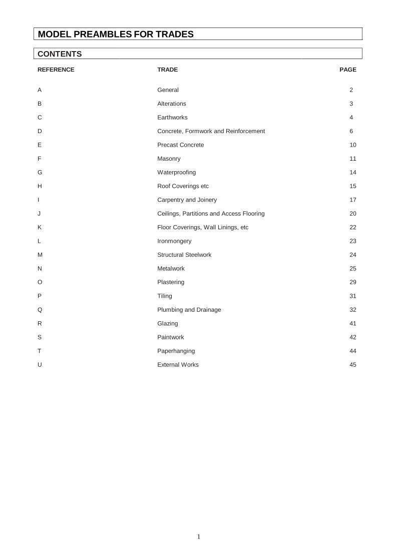
1
MODEL PREAMBLES FOR TRADES
CONTENTS
REFERENCE
TRADE
PAGE
A
General
2
B Alterations 3
C Earthworks 4
D Concrete, Formwork and Reinforcement 6
E Precast Concrete 10
F Masonry 11
G Waterproofing 14
H Roof Coverings etc 15
I Carpentry and Joinery 17
J Ceilings, Partitions and Access Flooring 20
K Floor Coverings, Wall Linings, etc 22
L Ironmongery 23
M Structural Steelwork 24
N Metalwork 25
O Plastering 29
P Tiling 31
Q Plumbing and Drainage 32
R Glazing 41
S Paintwork 42
T Paperhanging 44
U External Works 45
2
A. GENERAL
A.1 APPLICATION OF CLAUSES
These Model Preambles for Trades, and any Supplementary Preambles, shall be read in conjunction with and shall form part of the descriptions of items in the bills of quantities
Where descriptions or Supplementary Preambles in the bills of quantities differ from these Model Preambles for Trades, the descriptions or Supplementary Preambles in the bills of quantities shall take precedence. Where supplementary preambles differ from descriptions in the bills of quantities, the descriptions in the bills of quantities shall take precedence
Except where otherwise stated, all preambles contained in any individual Trade Preamble shall apply equally to any work of a similar nature in all other trades
A.2 ABBREVIATIONS
The following abbreviations shall apply: AASHTO – American Association of State Highway and Transportation Officials AISI – American Institute of Steel Industries BS – British Standard CKS – Coordinating Specifications issued by the Central Coordinating Committee under
the auspices of the South African Bureau of Standards CSIR – Council for Scientific and Industrial Research SANS – South African National Standards and the number following shall refer to
the relevant specification or code of practice as the case may be
A.3 MATERIALS AND WORKMANSHIP
Materials and workmanship shall be the best of their respective kinds. Only new and undamaged materials shall be used in the Works. Materials to be permanently installed into the works shall not be used for any temporary purposes on site. Work shall be to the approval of the Principal Agent and shall be executed in accordance with the relevant manufacturer’s written recommendations and instructions where applicable
A.4 PROPRIETARY PRODUCTS
For the purposes of submission of tenders, rates for items described in the bills of quantities by trade names, catalogue references, etc shall be for the particular type and manufacture specified
The approval of the Principal Agent shall be obtained prior to any substitution and where products or materials etc other than those specified are used, adjustments in the rates will be made if necessary
A.5 ASSEMBLING
Rates for manufactured items shall include assembling complete and handing over in proper working order
A.6 REFERENCES IN DESCRIPTIONS
Any references given in brackets at the end of certain descriptions shall refer to the relevant references on the drawings or schedules
A.7 WATER
Water shall be clean and free from injurious amounts of acids, alkalis, organic matter and other substances and shall be suitable for its intended use
A.8 APPLICATION OF THE NATIONAL BUILDING REGULATIONS
All work shall be executed in accordance with the requirements of SANS 10400
A.9 ACCURACY IN BUILDINGS
The dimensional and positional accuracy of the buildings and their component parts shall comply with Grade II

3
requirements of SANS 10155 unless otherwise stated
A.10 REFERENCES TO OTHER DOCUMENTS
References in these “Model Preambles for Trades” to other documents, including SANS, CKS and BS, shall pertain to the latest edition thereof including all amendments thereto at the date for submission of the tender
4
B. ALTERATIONS
B.1 ALTERATIONS
In taking down and removing existing work the utmost care shall be observed to prevent any structural or other damage to remaining portions of the building. The Contractor shall ensure the stability of all structures during alteration work
Special care shall be exercised during the progress of the work to ensure that any electrical installations, water supply pipes, telephone and other services which may be encountered are not interfered with and notice shall be given to the Principal Agent if any disconnection or alterations become necessary
The Contractor shall take all precautions necessary to prevent any nuisance from dust whilst carrying out the work
B.2 MATERIALS FROM THE ALTERATIONS, CREDIT, ETC
Materials recovered from the alterations (except where described as to be re-used or to be handed over to the Employer) will become the property of the Contractor, who may allow credit in respect thereof where provided for in the bills of quantities. Such materials shall not be re-used in new work without written permission from the Principal Agent
Materials described as “removed” shall be removed from the site immediately.
Materials described as “handed over to the Employer” shall be carefully dismantled where necessary, neatly stored under cover on the site where directed and protected from damage, until required
Materials described as “set aside for re-use” shall be carefully dismantled where necessary, cleaned, neatly stored under cover and protected from damage until required for re-use. Any damage caused to such materials during removal, storage or refixing shall be made good at the Contractor’s expense
B.3 DISPOSAL OF DEBRIS ETC
The Contractor shall be responsible for the removal from the site of all materials, debris and rubbish resulting from the alterations
B.4 MAKING GOOD DAMAGED WORK
The Contractor shall make good in all trades to existing work where damaged or disturbed through the alterations with all necessary new materials to match the existing
B.5 FORMING NEW OPENINGS OR ALTERING OPENINGS IN EXISTING WALLS
Where new openings are formed or openings altered in existing walls, the wall above the opening shall be broken out and a new brick, in situ concrete or prestressed concrete lintel inserted, complete with all necessary reinforcement, formwork, turning piece, etc, the jambs and portions of openings as described shall be built up with new brickwork or blockwork properly toothed and bonded to existing, cavities of hollow walls shall be closed where necessary and finishes shall be made good all round and into reveals
B.6 BUILDING UP OPENINGS
Where existing openings are given in number as built up, the existing surfaces all round shall be prepared as necessary, brickwork or blockwork properly toothed and bonded to existing, wedged up to underside of existing lintel and finishes shall be made good on both sides
5
C. EARTHWORKS
C.1 DEMOLITIONS
C.1.1 Nature and extent
Descriptions of demolitions give a rough guide only as to the scope of the work. Tenderers are therefore advised to visit the site before submitting a tender and to acquaint themselves with the nature and extent of the work to be done and the value of recoverable materials which are not to be re-used or handed over to the Employer. Unless otherwise stated, loose furniture, kitchen and other equipment, apparatus, machinery, etc shall remain the property of the Employer and the removal thereof does not fall within the scope of this Contract
The Contractor shall completely demolish the buildings etc in a careful, skilful, practical and safe manner down to 150mm below ground level
Demolitions shall include breaking up and removing:
all floors and surface beds;
all external screen walls, steps, ramps, aprons, surface water channels, rainwater sumps, gulleys, etc attached to the building to be demolished;
all services, manholes, etc in ground to a point not less than 1m beyond the perimeter of the building including plugging off ends of all remaining pipes, drains, etc, filling in holes where necessary and ramming and levelling to ground level
Where only a portion of a building is to be demolished, it shall be done without damage to the remaining portion of the building. Any such damage shall be made good by the Contractor at his own expense
C.1.2 Notices etc
The Contractor shall, before commencing work, obtain all necessary authorisation for carrying out the work, by whatever means including the use of pneumatic equipment or blasting, give all necessary notices and pay all charges and fees in connection therewith. He shall also comply with all regulations pertaining to rodent extermination and he shall obtain the requisite Rodent Extermination Clearance Certificate and pay all necessary fees. All receipts and certificates shall be left in the safekeeping of the Principal Agent. All the abovementioned charges and fees shall be paid by the Contractor and included in his prices
The Contractor shall give ample notice to the Principal Agent and Local Authorities regarding any disconnections necessary prior to the removal or interruption of electrical or telephone cables, water and sanitary services etc
C.1.3 Loss
After the handing over of the site to the Contractor, the full risk of any loss or damage to buildings to be demolished shall be the responsibility of the Contractor and he shall take such precautions as he deems necessary against such loss or damage
C.1.4 Materials from the demolitions, credit, etc
Materials recovered from the demolitions will become the property of the Contractor, who may allow credit in respect thereof where provided for in the bills of quantities. Such materials shall not be re- used in any new work without written permission from the Principal Agent
C.1.5 Disposal of debris etc
The Contractor shall be responsible for the removal from the site of all materials, rubble, debris and rubbish resulting from the demolitions
C.2 SOIL INSECTICIDES
The application of soil insecticides shall be carried out in accordance with “The application of soil insecticides for the protection of buildings” - SANS 10124
6
C.3 FILLIN
C.3.1
G ETC
Filling generally
Filling over site shall be spread, levelled, watered and consolidated in layers not exceeding 300mm
Filling under floors and backfilling to excavations shall be suitable inert material, free from clay, vegetable matter, large stones, etc, having a maximum plasticity index of 10, spread, levelled and compacted to a density of at least 90% Mod. AASHTO
C.3.2 Hardcore
Hardcore shall be broken stone or other approved hard material graded from 25mm to 75mm with the finer material on top and shall be spread, levelled and consolidated
C.4 EXCAVATIONS
C.4.1 Classification of excavated material
“Hard rock” shall mean granite, quartzitic sandstone or other rock of similar hardness, the removal of which requires drilling, wedging and splitting or the use of explosives
“Soft rock” shall mean hard material the removal of which warrants the use of pneumatic tools and includes hard shale, ferricite, compact ouklip and material of similar hardness
“Earth” shall mean all ground other than that classified as “hard rock” or “soft rock” and shall include
3 made-up ground and any loose stones or pieces of concrete not exceeding 0,03m in volume
7
D. CONCRETE, FORMWORK AND REINFORCEMENT
D.1 SPECIFICATION FOR CONCRETE WORK GENERALLY All in situ concrete work (plain and reinforced) shall comply with SANS 1200G supplemented by the following Project Specification. Where SANS 1200G and the Project Specification are in conflict, the Project Specification shall take precedence
Wherever the term “Engineer” appears in SANS 1200G or in the following Project Specification this shall be deemed to mean the Principal Agent’s representative responsible for this section of the Works
PROJECT SPECIFICATION
The following amplifications, additions and amendments to SANS 1200G shall constitute the Project Specification. Clause numbers refer to either the existing clauses in SANS 1200G or to new clauses, which are related to the existing clauses
1. SCOPE
This clause is amended to include:
1.1 This specification does not cover the methods by which the finished structure is to be measured for the purpose of payment and the “Standard System of Measuring Building Work” shall apply
2. INTERPRETATIONS
2.1 SUPPORTING SPECIFICATIONS
Clause 2.1(b) shall not apply
2.2 APPLICATION This clause shall not apply
4. PLANT
4.5 FORMWORK
4.5.2 Finish
Unless otherwise stated the quality of all formwork shall be such that the finished surface of the concrete is “Rough” in terms of clause 5.2.1(a)
5. CONSTRUCTON
5.2 FORMWORK
5.2.1 Classification of Finishes
(a) Rough. No treatment of the surface of the concrete will be required after the
striking of the formwork. The finish of the concrete need not be more accurate than Degree of Accuracy III
(b) Smooth. Imperfections such as small fins, bulges, irregularities, surface
honeycombing and surface discolorations shall be made good and repaired by approved methods. The finish of the concrete shall be accurate to Degree of Accuracy II
(c) Special
(i) Smooth and fair
This class of finish requires the highest standard of concrete work, formwork, accuracy and technique
Concrete placed in any one structure to give this finish shall be made from cement and aggregates from the same source. The grading of the aggregate shall be kept constant
Formwork shall be metal, wrot timber or other approved material in new condition designed and constructed to suit the particular job in hand and with shutter bolts and joints between panels in a regular pattern approved by

8
the Principal Agent. Joints between panels shall be watertight, but the use of sealing tape which will mark the concrete shall not be permitted
9
Designated joints shall be in the position and of the details shown upon the working drawings. Should the Contractor wish to incorporate further construction joints or amend the position of those shown to suit his own requirements or technique, this may be allowed provided that all design considerations are met, that the prior approval of the Engineer is obtained and that any extra costs are borne by the Contractor
In the case of horizontal construction joints, the top edge of the concrete on the smooth and fair finished side shall be struck true and level with a trowel
Special care shall be taken to ensure that forms are clean and free of all pieces of tying wire, nails and other debris at the time of concreting
The standard of finish shall be such that upon removal of the formwork, no further treatment, other than treatment of bolt holes if required, shall be found necessary to provide a straight, smooth and uniform finish of good quality and consistent colour and texture, free of all honeycombing etc. Any defect shall be made good by either removing and replacing the defective concrete or, in certain instances only, by patching
5.5 CONCRETE
5.5.1.6 Prescribed mix concrete
Where prescribed mix concrete is specified the proportions of constituents, the maximum size of coarse aggregate and the estimated minimum compressive strength shall be as specified in the following table:
Class of Concrete
Estimated minimum compressive strength in MPa at 28 days
Maximum nominal size of coarse aggregate in mm
Proportions of Constituents
Cement (Parts)
Fine aggregate (Parts)
Coarse aggregate (Parts)
A 7 37,5 1 4 8
B 15 19 1 3 5
C 20 19 1 2,5 3,5
Cement shall comply with SANS 50917-1 of strength 32,5N or higher
Should cement and aggregates be mixed by volume, the contents of a 50kg 3
sack of cement shall be taken to be 0,033m
Notwithstanding the requirements contained in SANS 1200G, the Principal Agent may permit certain items of non-structural concrete to be mixed by hand
If the concrete is mixed by hand, it shall first be mixed in a dry state on a clean non-absorbent surface until it is of uniform colour and consistency. Just enough water shall then be added to permit mixing and working, at which stage the concrete shall continue to be mixed until it is of uniform colour and consistency
5.5.1.7 Strength concrete
Where strength concrete is specified it shall be designated by its specified strength followed by the size of stone used in its manufacture, eg 30 MPa/19mm
The water/cement ratio shall be as Table 5 of clause 5.5.1.5 for moderate exposure conditions
5.5.1.8 “No-Fines” concrete
“No-fines” concrete shall consist of one part cement to eight parts aggregate graded from minimum 6mm to maximum 13mm size
10
The quantity of water used shall be just sufficient to form a smooth grout which shall completely coat every particle of aggregate and also to ensure that the grout is just wet enough to form a small fillet at each point of contact between the stones. “No-fines” concrete mixed with excessive water, which results in a thin grout, which drops off the aggregate, will be rejected
“No-fines” concrete shall be placed in its final position within 20 minutes of mixing and shall be placed in continuous horizontal layers. Concrete shall be spade worked sufficiently to ensure that it fills the forms but vibrating, tamping or ramming will not be permitted
5.5.3.2 Ready-mixed concrete
The use of ready-mixed concrete and the acceptability of test results from a central concrete production facility shall be subject to the written approval of the Engineer
6. TOLERANCES
Degree of Accuracy II shall apply for all work unless otherwise stated
7. TESTS
7.1 FACILITIES AND FREQUENCY OF SAMPLING
7.1.2 Frequency of sampling
7.1.2.5 The frequency of sampling shall be as directed by the Engineer, but
not less than one set of cubes from every 50m³ cast
8. MEASUREMENT AND PAYMENT
This clause shall not apply
D.2 AGGREGATES OF LOW DENSITY
Aggregates of low density shall comply with SANS 794
D.3 HOLLOW BLOCKS, PREFABRICATED BLOCK BEAMS AND PLANKS, ETC
Blocks, block beams, planks, etc shall be fixed and supported in such a manner that no movement can take place before or during the casting of concrete. No broken components shall be used
D.4 SUPERVISION
A competent and experienced foreman shall superintend personally the whole of the concrete construction and pay special attention to:
(a) The quality, testing and mixing of materials, (b) The placing and compaction of concrete, (c) The construction and removal of formwork and (d) The sizes and position of reinforcement
The Contractor shall obtain the permission of the Principal Agent before commencing concreting of foundations or reinforced structure
No inspection, approval, authorisation to proceed, comment or instructions following from such an inspection, or failure of the Principal Agent to comment on any particular aspect of the work, shall be deemed to relieve the Contractor in any way from his obligation to ensure through his own supervision that the work is constructed in every way in accordance with the Drawings, Specification and Conditions of Contract, nor relieve him from his obligations to make good any fault or defect, nor shall it be deemed that there is any obligation on the Principal Agent to inspect all or any part of the Works or that such inspection is necessarily complete in every respect
D.5 GENERAL
Concrete

11
Rates for concrete work shall include all “construction joints” other than “designated joints” as defined in SANS 1200G clause 2.4.3 which are measured separately, and for the design of strength concrete mixes and all testing of concrete and materials other than compressive strength testing of concrete samples taken from concrete being placed in the Works. The Contractor shall only be entitled to payment for those samples and compressive strength tests called for by the Engineer and which pass the test requirements

12
2 Surface beds cast in panels shall be cast in panels approximately 9m
Formwork
Formwork to slabs and beams shall be cambered where required Rates for formwork to soffits shall include propping not exceeding 3,5m high unless otherwise described. Formwork to walls and columns is not exceeding 3,5m high above bearing level unless otherwise described
Reinforcement
Standard welded steel fabric reinforcement shall be as included in Table 1 of SANS 1024 and shall have 300mm wide laps.
The mass of binding wire is not included in the mass of the reinforcement and the cost thereof shall be included in the rates for the reinforcement
13
E. PRECAST CONCRETE
E.1 MATERIALS AND WORKMANSHIP
Materials and workmanship shall comply with the following
standards: Precast concrete paving slabs SANS 541
Cement, water, aggregates and reinforcement shall be as described under D. CONCRETE, FORMWORK AND REINFORCEMENT
E.2 CONCRETE
Concrete shall be as described under D. CONCRETE, FORMWORK AND REINFORCEMENT and unless otherwise stated shall be prescribed mix concrete Class C but with coarse aggregate of an appropriate size
E.3 MOULDS
Before each casting, moulds shall be coated with a suitable release agent which will not in any way discolour the surface of the finished product or impair its strength. Where items are described as “finished smooth from the mould” or as “precast terrazzo”, moulds shall be made to a high degree of accuracy and shall be such as to leave even and smooth surfaces
E.4 FINISHES TO BLOCKS
Where described as “precast terrazzo”, such surfaces shall have a facing of terrazzo described under O. PLASTERING. The facing shall be poured into the moulds in a wet state (not dry pressed) and thoroughly worked up against finished faces to ensure that it finishes smooth from the mould
Projections shall be rubbed off and faces shall be of even colour and free from blemishes, cracks and other imperfections. Salient angles shall be arris rounded
E.5 CASTING ETC
Items shall be suitably cured, shall not be handled whilst still green and shall not be built in within 21 days of casting
E.6 REINFORCEMENT
Unspecified reinforcement required for manufacturing, handling and erection purposes and for reinforcing projecting and other unwieldy portions of blocks shall be provided by the Contractor at his discretion
E.7 BEDDING, JOINTING AND POINTING
Blocks shall be bedded and jointed solidly in Class I mortar as described under F. MASONRY and shall be pointed with slightly keyed joints
Blocks finished with “precast terrazzo” shall have joints raked out and pointed with slightly keyed joints in tinted waterproofed mortar composed of one part cement and three parts sand to match terrazzo facing
E.8 GENERAL
Precast concrete work shall include reinforcement required for manufacturing, handling and erection purposes, steel rod or wire hooks and/or mortices for lewis bolts required for handling and transporting, any necessary temporary propping and strutting and bedding, jointing and pointing
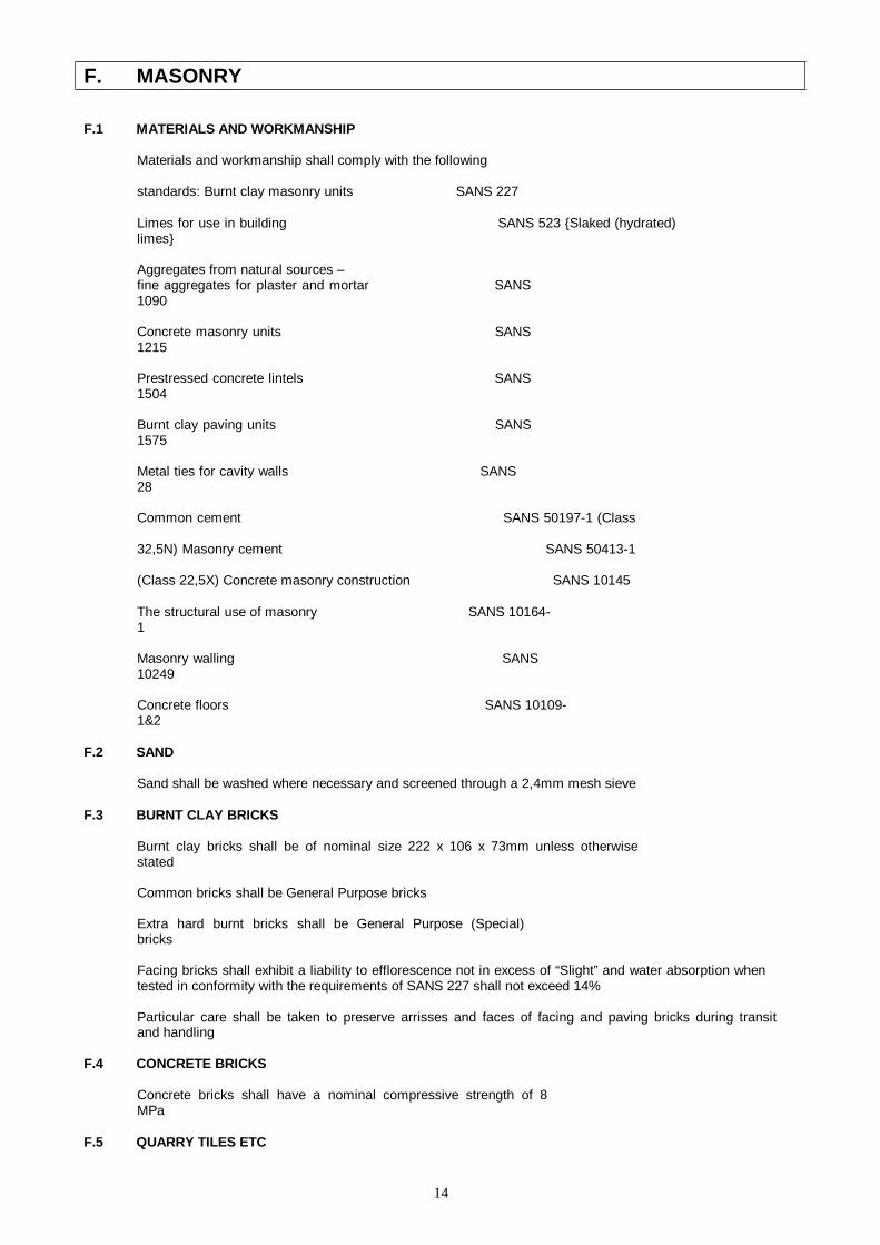
14
F. MASONRY
F.1 MATERIALS AND WORKMANSHIP
Materials and workmanship shall comply with the following
standards: Burnt clay masonry units SANS 227
Limes for use in building SANS 523 {Slaked (hydrated) limes}
Aggregates from natural sources – fine aggregates for plaster and mortar SANS 1090
Concrete masonry units SANS 1215
Prestressed concrete lintels SANS 1504
Burnt clay paving units SANS 1575
Metal ties for cavity walls SANS 28
Common cement SANS 50197-1 (Class
32,5N) Masonry cement SANS 50413-1
(Class 22,5X) Concrete masonry construction SANS 10145
The structural use of masonry SANS 10164-1
Masonry walling SANS 10249
Concrete floors SANS 10109-1&2
F.2 SAND
Sand shall be washed where necessary and screened through a 2,4mm mesh sieve
F.3 BURNT CLAY BRICKS
Burnt clay bricks shall be of nominal size 222 x 106 x 73mm unless otherwise stated
Common bricks shall be General Purpose bricks
Extra hard burnt bricks shall be General Purpose (Special) bricks
Facing bricks shall exhibit a liability to efflorescence not in excess of “Slight” and water absorption when tested in conformity with the requirements of SANS 227 shall not exceed 14%
Particular care shall be taken to preserve arrisses and faces of facing and paving bricks during transit and handling
F.4 CONCRETE BRICKS
Concrete bricks shall have a nominal compressive strength of 8 MPa
F.5 QUARRY TILES ETC

15
Quarry, cement and similar tiles shall be of approved manufacture, even in shape and size, free from cracks, twists or blemishes and uniform in colour
F.6 WIRE TIES
Wire ties shall be of galvanized steel of the single wire type for solid walls and either the “Butterfly” or Modified PWD type for hollow walls. Ties shall be of sufficient length to allow not less than 75mm of each end to be built into brickwork or embedded in concrete
F.7 BRICKWORK REINFORCEMENT
Brickwork reinforcement shall be manufactured from hard drawn steel wire conforming to BS 785 and shall consist of two 2,8mm diameter main wires with 2,5mm diameter cross wires at 300mm centres welded at intersections
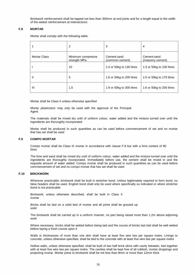
16
Brickwork reinforcement shall be lapped not less than 300mm at end joints and for a length equal to the width of the widest reinforcement at intersections
F.8 MORTAR
Mortar shall comply with the following table:
1
2
3
4
Mortar Class
Minimum compresive strength MPa
Cement:sand (common cement)
Cement:sand (masonry cement)
I
10
1:4 or 50kg to 130 litres
1:3 or 50kg to 100 litres
II
5
1:6 or 50kg to 200 litres
1:5 or 50kg to 170 litres
III
1,5
1:9 or 50kg to 300 litres
1:6 or 50kg to 200 litres
Mortar shall be Class II unless otherwise specified
Mortar plasticizers may only be used with the approval of the Principal Agent
The materials shall be mixed dry until of uniform colour, water added and the mixture turned over until the ingredients are thoroughly incorporated
Mortar shall be produced in such quantities as can be used before commencement of set and no mortar that has set shall be used
F.9 COMPO MORTAR
Compo mortar shall be Class III mortar in accordance with clause F.8 but with a lime content of 80 litres
The lime and sand shall be mixed dry until of uniform colour, water added and the mixture turned over until the ingredients are thoroughly incorporated. Immediately before use, the cement shall be mixed in and the requisite amount of water added. Compo mortar shall be produced in such quantities as can be used before commencement of set and no compo mortar that has set shall be used
F.10 BRICKWORK
Wherever practicable, brickwork shall be built in stretcher bond. Unless legitimately required to form bond, no false headers shall be used. English bond shall only be used where specifically so indicated or where stretcher bond is not practicable
Brickwork, unless otherwise described, shall be built in Class II mortar
Bricks shall be laid on a solid bed of mortar and all joints shall be grouted up solid
The brickwork shall be carried up in a uniform manner, no part being raised more than 1,2m above adjoining work
Where necessary, bricks shall be wetted before being laid and the course of bricks last laid shall be well wetted before laying a fresh course upon it
Walls in thicknesses of more than one skin shall have at least five wire ties per square metre. Linings to concrete, unless otherwise specified, shall be tied to the concrete with at least five wire ties per square metre
Hollow walls, unless otherwise specified, shall be built of two half brick skins with cavity between, tied together with at least five wire ties per square metre. The cavities shall be kept free of all rubbish, mortar droppings and projecting mortar. Mortar joints to brickwork shall be not less than 8mm or more than 12mm thick
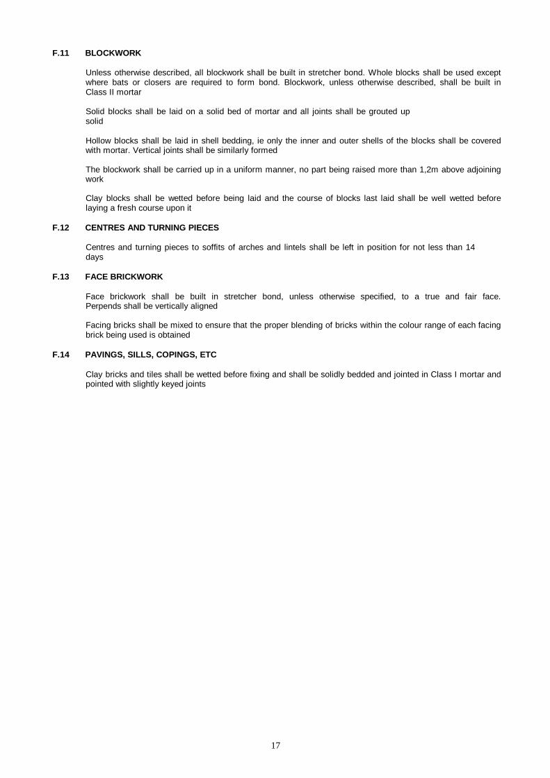
17
F.11 BLOCKWORK
Unless otherwise described, all blockwork shall be built in stretcher bond. Whole blocks shall be used except where bats or closers are required to form bond. Blockwork, unless otherwise described, shall be built in Class II mortar
Solid blocks shall be laid on a solid bed of mortar and all joints shall be grouted up solid
Hollow blocks shall be laid in shell bedding, ie only the inner and outer shells of the blocks shall be covered with mortar. Vertical joints shall be similarly formed
The blockwork shall be carried up in a uniform manner, no part being raised more than 1,2m above adjoining work
Clay blocks shall be wetted before being laid and the course of blocks last laid shall be well wetted before laying a fresh course upon it
F.12 CENTRES AND TURNING PIECES
Centres and turning pieces to soffits of arches and lintels shall be left in position for not less than 14 days
F.13 FACE BRICKWORK
Face brickwork shall be built in stretcher bond, unless otherwise specified, to a true and fair face. Perpends shall be vertically aligned
Facing bricks shall be mixed to ensure that the proper blending of bricks within the colour range of each facing brick being used is obtained
F.14 PAVINGS, SILLS, COPINGS, ETC
Clay bricks and tiles shall be wetted before fixing and shall be solidly bedded and jointed in Class I mortar and pointed with slightly keyed joints
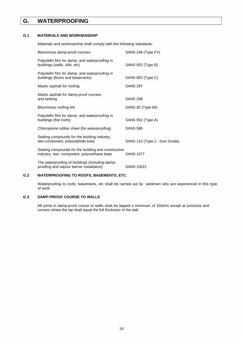
18
G. WATERPROOFING
G.1 MATERIALS AND WORKMANSHIP
Materials and workmanship shall comply with the following standards:
Bituminous damp-proof courses SANS 248 (Type FV)
Polyolefin film for damp- and waterproofing in buildings (walls, sills, etc) SANS 952 (Type B)
Polyolefin film for damp- and waterproofing in buildings (floors and basements) SANS 952 (Type C)
Mastic asphalt for roofing SANS 297
Mastic asphalt for damp-proof courses and tanking SANS 298
Bituminous roofing felt SANS 92 (Type 60)
Polyolefin film for damp- and waterproofing in buildings (flat roofs) SANS 952 (Type A)
Chloroprene rubber sheet (for waterproofing) SANS 580
Sealing compounds for the building industry, two-component, polysulphide base SANS 110 (Type 2 - Gun Grade)
Sealing compounds for the building and construction industry, two- component, polyurethane base SANS 1077
The waterproofing of buildings (including damp- proofing and vapour barrier installation) SANS 10021
G.2 WATERPROOFING TO ROOFS, BASEMENTS, ETC
Waterproofing to roofs, basements, etc shall be carried out by workmen who are experienced in this type of work
G.3 DAMP-PROOF COURSE TO WALLS
All joints in damp-proof course to walls shall be lapped a minimum of 150mm except at junctions and corners where the lap shall equal the full thickness of the wall
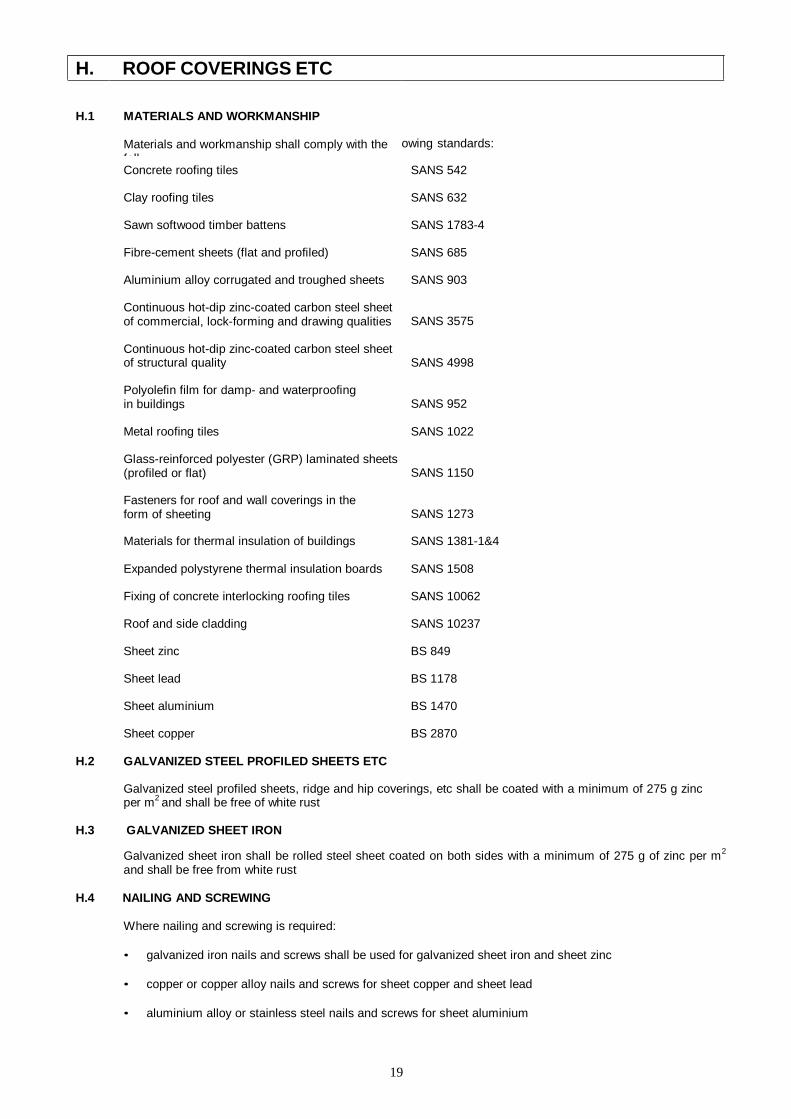
19
H. ROOF COVERINGS ETC
H.1
MATERIALS AND WORKMANSHIP
Materials and workmanship shall comply with the foll
owing standards:
Concrete roofing tiles SANS 542
Clay roofing tiles SANS 632
Sawn softwood timber battens SANS 1783-4
Fibre-cement sheets (flat and profiled) SANS 685
Aluminium alloy corrugated and troughed sheets SANS 903
Continuous hot-dip zinc-coated carbon steel sheet of commercial, lock-forming and drawing qualities
SANS 3575
Continuous hot-dip zinc-coated carbon steel sheet of structural quality
SANS 4998
Polyolefin film for damp- and waterproofing in buildings
SANS 952
Metal roofing tiles SANS 1022
Glass-reinforced polyester (GRP) laminated sheets (profiled or flat)
SANS 1150
Fasteners for roof and wall coverings in the form of sheeting
SANS 1273
Materials for thermal insulation of buildings SANS 1381-1&4
Expanded polystyrene thermal insulation boards SANS 1508
Fixing of concrete interlocking roofing tiles SANS 10062
Roof and side cladding SANS 10237
Sheet zinc BS 849
Sheet lead BS 1178
Sheet aluminium BS 1470
Sheet copper BS 2870
H.2 GALVANIZED STEEL PROFILED SHEETS ETC
Galvanized steel profiled sheets, ridge and hip coverings, etc shall be coated with a minimum of 275 g zinc per m2 and shall be free of white rust
H.3 GALVANIZED SHEET IRON
Galvanized sheet iron shall be rolled steel sheet coated on both sides with a minimum of 275 g of zinc per m2
and shall be free from white rust
H.4 NAILING AND SCREWING
Where nailing and screwing is required:
• galvanized iron nails and screws shall be used for galvanized sheet iron and sheet zinc
• copper or copper alloy nails and screws for sheet copper and sheet lead
• aluminium alloy or stainless steel nails and screws for sheet aluminium

20
H.5 LAPS
Sheet metal flashings shall have minimum 100mm laps and linings to valleys, secret gutters, etc minimum 225mm laps
H.6 GENERAL
Rates for profiled sheet roofing and rolled edges, ridge and hip coverings, flashing pieces, etc of metal, fibre- cement, plastic, etc shall include fixing accessories

21
I. CARPENTRY AND JOINERY
I.1 MATERIALS AND WORKMANSHIP
Materials and workmanship shall comply with the following
standards: Sawn softwood timber : General requirements SANS
1783-1
Sawn softwood timber : Stress-graded structural timber and timber for frame wall construction SANS 1783-2
Sawn softwood timber : Brandering and battens SANS 1783-4
Softwood flooring boards SANS 629
Hardwood furniture timber SANS 1099
Hardwood block and strip flooring SANS 281
Wooden ceiling and panelling boards SANS 1039
Laminated timber (glulam) SANS 1460
Gypsum plasterboard SANS 266
Fibreboard products SANS 540
Wood-wool panels (cement bonded) SANS 637
Fibre-cement sheets (flat and profiled) SANS 685
Fibre-cement boards SANS 803
Plywood and composite board SANS 929
Wooden ceiling and panelling boards SANS 1039
Particle boards SANS 50312-1to7
Decorative laminates SANS 4586
Wooden doors SANS 545
Fire doors SANS 1253
Materials for thermal insulation of buildings SANS 1381-1,2,4&6
Expanded polystyrene thermal insulation boards SANS 1508

22
Mild steel nails SANS 820
Metal screws for wood SANS 1171
Wood-preserving creosote SANS 539
Softwood shall bear the relevant SABS mark and shall be ordered in the sizes in which it will be used as no scantlings of marked timber will be allowed. Should SABS marked timber be unavailable, the Principal Agent’s prior permission shall be obtained before using unmarked timber
I.2 HARDWOODS
All hardwoods shall be specially selected, well seasoned, free from sapwood and well kiln dried. Meranti shall be Red or Medium Brown Meranti, even in grain and colour, selected from “Standard and Better” quality from Malaysia
23
I.3 INFECTION AND PRE-TREATMENT OF TIMBER
All timber used on the site, whether for permanent or temporary work, shall be free of borer or other beetle and termite infection. If the work under this contract falls within an area designated under Government Notice R2577 of 197812-29, permanent softwood fixed in the building shall be treated against borer etc in accordance with Government Notice R451 of 1969-03-28 using Class B or C preservative
When treated timbers are cut, the cut surfaces shall be effectively brushed with at least two coats of preservative solution
I.4 CONSTRUCTION IN GENERAL
Where applicable, construction methods shall comply with SANS 10082. Wood and laminate flooring shall be installed in accordance with SANS 10043. Roof trusses shall be manufactured, erected and braced in accordance with SANS 10243
I.5 STRUCTURAL TIMBER
Timbers generally shall be in single lengths and jointing of timbers will only be permitted when the required length is unobtainable. Only the absolute minimum of joints to obtain a particular length will be permitted and such joints are to be evenly spaced along the length of the timber
Finger-jointing of structural timber will be permitted, in which case it shall be manufactured in accordance with SANS 10096
I.6 PLATE NAILED TIMBER ROOF TRUSSES
Plate nailed timber roof trusses shall be of approved design and manufacture and constructed with softwood structural timber by a truss Fabricator holding a current Certificate of Competence awarded by the Institute of Timber Construction
Each roof truss shall have all its members accurately cut and closely butted together and rigidly fixed by CSIR approved patented galvanized metal spiked connectors, precision pressed on both sides of each intersection by an approved method, all in accordance with the manufacturer’s instructions
The design, manufacture and transportation of the roof trusses, bracing, etc shall be under the control of a registered Structural Engineer in accordance with SANS 1900, SANS 10160 and SANS 10163, who shall, after erection, provide a certificate confirming that the design, manufacture, transportation, erection and bracing has been carried out in accordance with this specification
The design shall include for all live loads, wind loads and for dead loads imposed by roof covering, purlins, ceilings, etc
Fully detailed shop drawings of all trusses etc, indicating sizes, bracing, loading, etc, shall be submitted to the Principal Agent for approval prior to fabrication
Unless specific erection instructions are given, erection shall be carried out in accordance with the procedures and recommendations of the manual “The Erection and Bracing of Timber Roof Trusses” published by the Institute for Timber Construction and the Council for Scientific and Industrial Research or as detailed by the designer
Roof trusses and bracing shall include design and preparation of shop drawings
I.7 TONGUED AND GROOVED BOARDING
Tongued and grooved boards for floors, panelling, etc shall be in long varying lengths with joints tightly cramped up and secret nailed. Flooring boarding shall be flush jointed with staggered heading joints and machine sanded after fixing
I.8 JOINERY
Skirtings, cornices, rails, etc shall be in single lengths wherever practicable and shall have splayed heading joints where necessary. Skirtings shall be trenched at back
All horns of door frames shall be checked and splayed back where frames are fixed projecting or flush with surface and built in

24
Heads of screws in exposed faces of hardwood joinery shall be sunk and match pelleted
Joinery shall have arris rounded angles and shall be blocked and planted on
25
I.9 VENEERS
All face veneers shall be of kiln dried timber, free from knots, cracks, patchwork, sapwood and other defects, selected and glued, dried and machine-sanded to a smooth finish. All veneers shall be applied under hydraulic pressure
I.10 DOORS
Flush doors shall have solid timber edge strips with concealed edges. Where doors are to be finished with a transparent finish, the veneer and the edge strips shall be timber of the same species and as far as possible of matching colour. Unless otherwise described all flush doors shall be of interior quality, but where exterior quality doors are specified the glue used shall be of the WBP type
Framed and ledged batten doors described as filled in with V-jointed boarding shall be filled in flush on one side with tongued and grooved vertical boarding, V-jointed on one or both sides and of the thickness stated. The boarding shall be in narrow widths, closely cramped up, rebated or tongued on outer edges and housed to grooves in stiles and rails and twice countersunk brass screwed at each intersection with ledges and braces and the inner edges of the abutting stiles and rails shall be chamfered to form a V-joint at junction with the board
Unless otherwise described double doors shall have rebated meeting stiles
I.11 FIXING
All nails and screws shall be of the size, length and type appropriate to their respective uses. All screws for hardwood joinery work shall be brass
Items described as “plugged” shall be screwed to fibre, plastic or metal plugs at not exceeding 600mm centres. Where items are described as “bolted”, the bolts have been given separately
I.12 ADHESIVES
Adhesives shall comply with BS 1204 and 4071 where applicable. Adhesives used in the manufacture of external joinery exposed to excessive moisture (eg kitchen and laboratory worktops) shall be of the WBP type
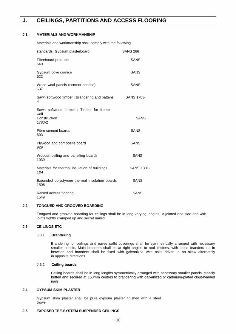
26
J. CEILINGS, PARTITIONS AND ACCESS FLOORING
J.1 MATERIALS AND WORKMANSHIP
Materials and workmanship shall comply with the following
standards: Gypsum plasterboard SANS 266
Fibreboard products SANS 540
Gypsum cove cornice SANS 622
Wood-wool panels (cement-bonded) SANS 637
Sawn softwood timber : Brandering and battens SANS 1783-4
Sawn softwood timber : Timber for frame wall Construction SANS 1783-2
Fibre-cement boards SANS 803
Plywood and composite board SANS 929
Wooden ceiling and panelling boards SANS 1039
Materials for thermal insulation of buildings SANS 1381-1&4
Expanded polystyrene thermal insulation boards SANS 1508
Raised access flooring SANS 1549
J.2 TONGUED AND GROOVED BOARDING
Tongued and grooved boarding for ceilings shall be in long varying lengths, V-jointed one side and with joints tightly cramped up and secret nailed
J.3 CEILINGS ETC
J.3.1 Brandering
Brandering for ceilings and eaves soffit coverings shall be symmetrically arranged with necessary smaller panels. Main branders shall be at right angles to roof timbers, with cross branders cut in between and branders shall be fixed with galvanized wire nails driven in on skew alternately in opposite directions
J.3.2 Ceiling boards
Ceiling boards shall be in long lengths symmetrically arranged with necessary smaller panels, closely butted and secured at 150mm centres to brandering with galvanized or cadmium-plated clout-headed nails
J.4 GYPSUM SKIM PLASTER
Gypsum skim plaster shall be pure gypsum plaster finished with a steel trowel
J.5 EXPOSED TEE-SYSTEM SUSPENDED CEILINGS

27
The ceiling panels shall be as described in the items and the panels shall be stiffened at back as recommended by the manufacturer to prevent bowing or sagging
The exposed surfaces of all ceiling panels and supporting members shall be uniform in colour and free from surface blemishes
The suspension grid system shall be an approved patent suspension system comprising 38mm galvanized steel main and cross tee bearers spaced in both directions at centres to suit sizes of ceiling panels used, with the cross bearers fitted between and notched to form flush fit with main bearers. The exposed flange of the tees shall be 25mm wide, covered with a rolled aluminium cap painted a low sheen satin white. Cornices etc shall be as described in the items and shall be finished to match the exposed tees
28
The main tee bearers shall have holes for cross tees at 300mm centres and holes for hangers at 50mm centres. In addition, main and cross tee bearers shall be holed as necessary for and provided with timber wedges or steel clips where recommended by the manufacturer to prevent ceiling panels from lifting
The web of the exposed cross tee bearers shall extend to form a positive interlock with the main tee bearers and the lower flange shall be cut back to provide a joint free appearance
All hangers shall be galvanized and shall be at centres to meet the requirements of the specification with one end fixed to the suspension grid main bearers and the other end fitted with suitable galvanized fixing cleat securely fixed to the structure. Fixing points shall be agreed to by the Principal Agent before any power shot fixings are made. Hangers shall not be suspended from air-conditioning ducts. Where recommended by the manufacturer, hangers shall be of the rigid type
Component parts and fixings shall be non-corrosive and able to withstand atmospheric pollution. Surfaces of aluminium which are in contact with other materials when fixed, particularly metals, shall be suitably insulated to prevent electrolytic corrosion
Ceilings shall comprise hangers, suspension grid system and ceiling panels, shall be constructed in a manner suitable for carrying air-conditioning diffusers and light fittings in the positions required, shall be set out to layouts approved by the Principal Agent and shall have the standard suspension systems modified as necessary to work around any pipes or light fittings
J.6 FLUSH PLASTERED SUSPENDED CEILINGS
Gypsum plasterboard panels of the specified thickness generally in 1200mm widths and in long lengths shall be fixed grey side down with self-tapping screws to the suspension system with the joints between boards loosely butt jointed and covered with 50mm wide strips of self-adhesive fibre tape
The plasterboard panels shall be finished with gypsum skim plaster trowelled to a smooth polished surface to the thickness etc recommended by the manufacturer
The suspension system shall be an approved patent concealed suspension system consisting of galvanized mild steel bearers suspended on approved non-rusting metal hangers spaced generally at 1200mm centres or to suit layout of air-conditioning ducts and other services etc above ceiling with one end bolted to the bearer and the other end fitted with a galvanized fixing cleat securely fixed to the structure as required
Fixing points shall be agreed to by the Principal Agent before any power shot fixings are made. Hangers shall not be suspended from air-conditioning ducting
Ceilings shall comprise hangers, suspension system, ceiling panels and plaster finish, shall be constructed in a manner suitable for carrying air-conditioning diffusers and light fittings in the positions required, shall be set out to layouts approved by the Principal Agent and shall have the standard suspension system modified as necessary to work around any pipes or light fittings
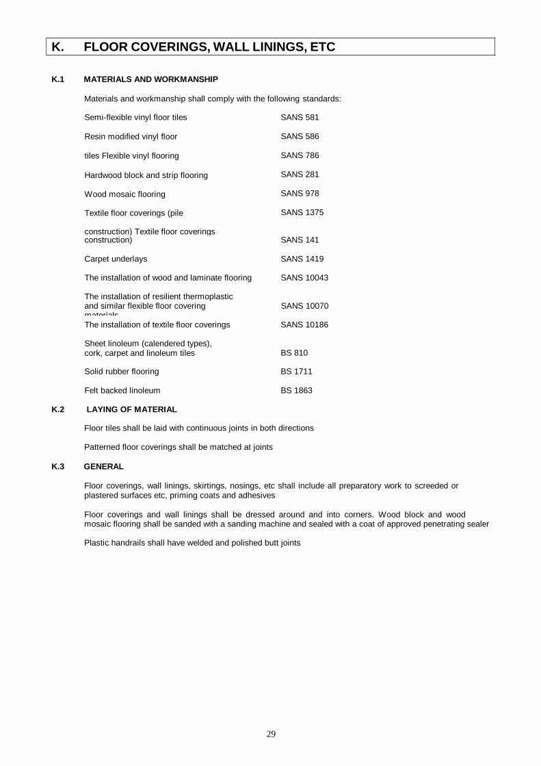
29
K. FLOOR COVERINGS, WALL LININGS, ETC
K.1 MATERIALS AND WORKMANSHIP
Materials and workmanship shall comply with the following standards:
Semi-flexible vinyl floor tiles
Resin modified vinyl floor
tiles Flexible vinyl flooring
Hardwood block and strip flooring
Wood mosaic flooring
Textile floor coverings (pile
construction) Textile floor coverings
SANS 581
SANS 586
SANS 786
SANS 281
SANS 978
SANS 1375
construction) SANS 141
Carpet underlays SANS 1419
The installation of wood and laminate flooring SANS 10043
The installation of resilient thermoplastic and similar flexible floor covering materials
SANS 10070
The installation of textile floor coverings SANS 10186
Sheet linoleum (calendered types), cork, carpet and linoleum tiles
BS 810
Solid rubber flooring BS 1711
Felt backed linoleum BS 1863
K.2 LAYING OF MATERIAL
Floor tiles shall be laid with continuous joints in both directions
Patterned floor coverings shall be matched at joints
K.3 GENERAL
Floor coverings, wall linings, skirtings, nosings, etc shall include all preparatory work to screeded or plastered surfaces etc, priming coats and adhesives
Floor coverings and wall linings shall be dressed around and into corners. Wood block and wood mosaic flooring shall be sanded with a sanding machine and sealed with a coat of approved penetrating sealer
Plastic handrails shall have welded and polished butt joints
30
L. IRONMONGERY
L.1 MATERIALS AND WORKMANSHIP
Materials and workmanship shall comply with the following
standards: Locks, latches and associated furniture for doors. (Domestic type) SANS 4
Kitchen cupboards: Built-in and free-standing SANS 1385
Single action closers SANS 1510
Padlocks SANS 1533
Fasteners SANS 1700
Chalk writing boards for schools CKS 36
L.2 KEYS
Locks shall have the minimum possible number of interchangeable keys. Cylinder locks and locks described as “en suite” shall be clearly marked with consecutive numbers and each key shall be punched with the corresponding number of the relative lock
L.3 FIXING
Unless otherwise described, ironmongery is to be fixed to wood
Items described as “plugged” shall be screwed to fibre, plastic or metal plugs
Screws, bolts, etc for fixing of ironmongery shall be of matching metal and finish, except for aluminium ironmongery or ironmongery fixed to aluminium in which cases stainless steel screws may be used
All necessary preparation of pressed steel door frames for the fixing of ironmongery to the frames has been included with the pressed steel door frames
L.4 KITCHEN CUPBOARDS
Steel cupboards shall be finished with baked enamel. Tops of floor cupboards shall have laminated plastic covering
Cupboards shall be fitted with all necessary hinges, handles, catches, etc. Cupboards shall be securely fixed with all necessary screws and fibre, plastic or metal plugs
Where cupboards are described as a “series”, tops shall be continuous and cupboards shall be bolted or screwed together, including bolts, screws, holes, etc
31
M. STRUCTURAL STEELWORK
M.1 SPECIFICATION
All structural steelwork shall comply with SANS 1200H or 1200HA as applicable. Structural fasteners shall comply with SANS 1700
Whenever the term “Engineer” appears in SANS 1200H or 1200HA or in the following Project Specification this shall be deemed to mean the Principal Agent’s representative responsible for this section of the Works
M.2 PROJECT SPECIFICATION INCORPORATING AMPLIFICATIONS, ADDITIONS AND AMENDMENTS TO
SANS 1200H AND 1200HA
The following amplifications, additions and amendments to SANS 1200H and SANS 1200HA shall apply and clause numbers refer to either the existing clauses in the relevant SANS or to new clauses which are related to the clauses therein
SANS 1200H
3.1.1 Weldable structural steel
Weldable structural steel shall comply with SANS 1431
5.1.2 Contractor provides shop details
The Contractor shall be responsible for the preparation of all shop detail drawings
5.1.3 Engineer provides shop details
This clause shall not apply
5.3.9 Protective treatment
Structural steelwork shall be cleaned and prepared by wire brushing in accordance with SANS 10064 and all surfaces shall be primed as specified to a minimum dry film thickness of 30 micrometres before leaving the workshop. Upon delivery to the site and again after erection all bared surfaces shall be made good with similar primer
8. Measurement and payment
This clause shall not apply
SANS 1200HA
5.2.10 Protective treatment
Structural steelwork shall be cleaned and prepared by wire brushing in accordance with SANS 10064 and all surfaces shall be primed as specified to a minimum dry film thickness of 30 micrometres before leaving the workshop. Upon delivery to the site and again after erection all bared surfaces shall be made good with similar primer
5.3.7 Repairs to paint and site painting
This clause shall not apply
8. Measurement and payment
This clause shall not apply
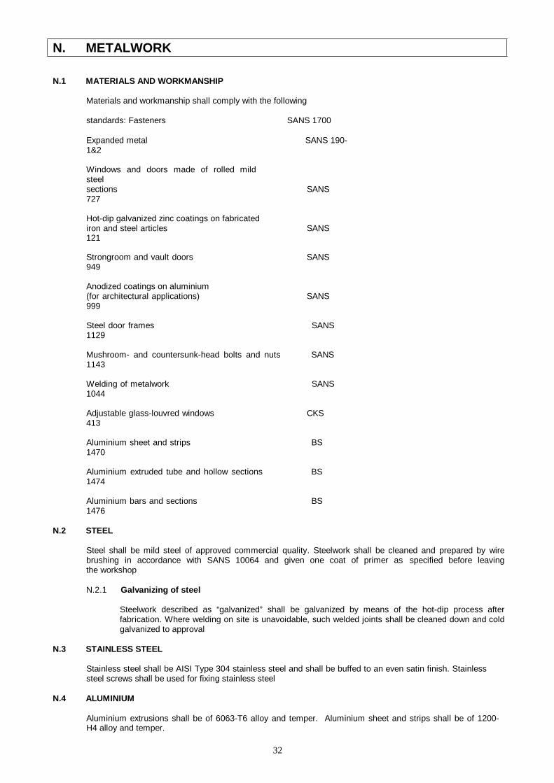
32
N. METALWORK
N.1 MATERIALS AND WORKMANSHIP
Materials and workmanship shall comply with the following
standards: Fasteners SANS 1700
Expanded metal SANS 190-1&2
Windows and doors made of rolled mild steel sections SANS 727
Hot-dip galvanized zinc coatings on fabricated iron and steel articles SANS 121
Strongroom and vault doors SANS 949
Anodized coatings on aluminium (for architectural applications) SANS 999
Steel door frames SANS 1129
Mushroom- and countersunk-head bolts and nuts SANS 1143
Welding of metalwork SANS 1044
Adjustable glass-louvred windows CKS 413
Aluminium sheet and strips BS 1470
Aluminium extruded tube and hollow sections BS 1474
Aluminium bars and sections BS 1476
N.2 STEEL
Steel shall be mild steel of approved commercial quality. Steelwork shall be cleaned and prepared by wire brushing in accordance with SANS 10064 and given one coat of primer as specified before leaving the workshop
N.2.1 Galvanizing of steel
Steelwork described as “galvanized” shall be galvanized by means of the hot-dip process after fabrication. Where welding on site is unavoidable, such welded joints shall be cleaned down and cold galvanized to approval
N.3 STAINLESS STEEL
Stainless steel shall be AISI Type 304 stainless steel and shall be buffed to an even satin finish. Stainless steel screws shall be used for fixing stainless steel
N.4 ALUMINIUM
Aluminium extrusions shall be of 6063-T6 alloy and temper. Aluminium sheet and strips shall be of 1200-H4 alloy and temper.

33
Joints in all aluminium members shall be formed in an approved manner so that the joints are practically invisible. Screw heads, pins, rivets, etc shall be concealed as far as possible. 300 Series stainless steel screws and bolts shall be used for jointing and fixing aluminium work
The surfaces of all aluminium which are in contact with other materials when fixed shall be suitably insulated with a non-absorbent insulating material to prevent corrosion. All aluminium work shall be suitably protected against damage, deterioration or discolouration caused by mortar droppings, paint, etc by taping with removable tape, covering with temporary casings or by covering with motor oil
N.4.1 Anodizing of aluminium
Aluminium described as “anodized” shall be treated with Grade 25 coating thickness for exterior use or Grade 15 for interior use as specified, to the required finish. All alloys to be anodized shall be suited to anodizing
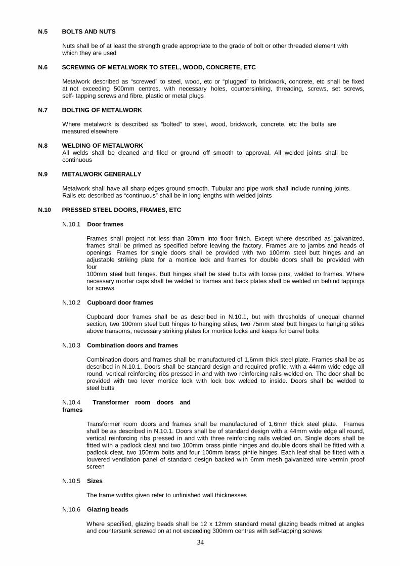
34
N.5 BOLTS AND NUTS
Nuts shall be of at least the strength grade appropriate to the grade of bolt or other threaded element with which they are used
N.6 SCREWING OF METALWORK TO STEEL, WOOD, CONCRETE, ETC
Metalwork described as “screwed” to steel, wood, etc or “plugged” to brickwork, concrete, etc shall be fixed at not exceeding 500mm centres, with necessary holes, countersinking, threading, screws, set screws, self- tapping screws and fibre, plastic or metal plugs
N.7 BOLTING OF METALWORK
Where metalwork is described as “bolted” to steel, wood, brickwork, concrete, etc the bolts are measured elsewhere
N.8 WELDING OF METALWORK
All welds shall be cleaned and filed or ground off smooth to approval. All welded joints shall be continuous
N.9 METALWORK GENERALLY
Metalwork shall have all sharp edges ground smooth. Tubular and pipe work shall include running joints. Rails etc described as “continuous” shall be in long lengths with welded joints
N.10 PRESSED STEEL DOORS, FRAMES, ETC
N.10.1 Door frames
Frames shall project not less than 20mm into floor finish. Except where described as galvanized, frames shall be primed as specified before leaving the factory. Frames are to jambs and heads of openings. Frames for single doors shall be provided with two 100mm steel butt hinges and an adjustable striking plate for a mortice lock and frames for double doors shall be provided with four 100mm steel butt hinges. Butt hinges shall be steel butts with loose pins, welded to frames. Where necessary mortar caps shall be welded to frames and back plates shall be welded on behind tappings for screws
N.10.2 Cupboard door frames
Cupboard door frames shall be as described in N.10.1, but with thresholds of unequal channel section, two 100mm steel butt hinges to hanging stiles, two 75mm steel butt hinges to hanging stiles above transoms, necessary striking plates for mortice locks and keeps for barrel bolts
N.10.3 Combination doors and frames
Combination doors and frames shall be manufactured of 1,6mm thick steel plate. Frames shall be as described in N.10.1. Doors shall be standard design and required profile, with a 44mm wide edge all round, vertical reinforcing ribs pressed in and with two reinforcing rails welded on. The door shall be provided with two lever mortice lock with lock box welded to inside. Doors shall be welded to steel butts
N.10.4 Transformer room doors and frames
Transformer room doors and frames shall be manufactured of 1,6mm thick steel plate. Frames shall be as described in N.10.1. Doors shall be of standard design with a 44mm wide edge all round, vertical reinforcing ribs pressed in and with three reinforcing rails welded on. Single doors shall be fitted with a padlock cleat and two 100mm brass pintle hinges and double doors shall be fitted with a padlock cleat, two 150mm bolts and four 100mm brass pintle hinges. Each leaf shall be fitted with a louvered ventilation panel of standard design backed with 6mm mesh galvanized wire vermin proof screen
N.10.5 Sizes
The frame widths given refer to unfinished wall thicknesses
N.10.6 Glazing beads
Where specified, glazing beads shall be 12 x 12mm standard metal glazing beads mitred at angles and countersunk screwed on at not exceeding 300mm centres with self-tapping screws
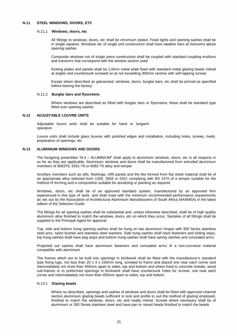
35
N.11 STEEL WINDOWS, DOORS, ETC
N.11.1 Windows, doors, etc
All fittings to windows, doors, etc shall be chromium plated. Fixed lights and opening sashes shall be in single squares. Windows etc of single unit construction shall have weather bars at transoms above opening sashes
Composite windows not of single piece construction shall be coupled with standard coupling mullions and transoms that correspond with the window section used
Kicking plates and panels shall be 1,6mm metal plate fixed with standard metal glazing beads mitred at angles and countersunk screwed on at not exceeding 300mm centres with self-tapping screws
Except where described as galvanized, windows, doors, burglar bars, etc shall be primed as specified before leaving the factory
N.11.2 Burglar bars and flyscreens
Where windows are described as fitted with burglar bars or flyscreens, these shall be standard type fitted over opening sashes
N.12 ADJUSTABLE LOUVRE UNITS
Adjustable louvre units shall be suitable for hand or longarm operation
Louvre units shall include glass louvres with polished edges and installation, including holes, screws, rivets, preparation of openings, etc
N.13 ALUMINIUM WINDOWS AND DOORS
The foregoing preambles “N.4 – ALUMINIUM” shall apply to aluminium windows, doors, etc in all respects in so far as they are applicable. Aluminium windows and doors shall be manufactured from extruded aluminium members of 6063T6, 6261-T6 or 6082-T6 alloy and temper
Ancillary members such as sills, flashings, infill panels and the like formed from flat sheet material shall be of an appropriate alloy selected from 1200, 3004 or 5251 complying with BS 1470 of a temper suitable for the method of forming and a composition suitable for anodizing or painting as required
Windows, doors, etc shall be of an approved standard system, manufactured by an approved firm experienced in this type of work, and shall meet with the minimum recommended performance requirements as set out by the Association of Architectural Aluminium Manufacturers of South Africa (AAAMSA) in the latest edition of the Selection Guide
The fittings for all opening sashes shall be substantial and, unless otherwise described, shall be of high quality aluminium alloy finished to match the windows, doors, etc on which they occur. Samples of all fittings shall be supplied to the Principal Agent for approval
Top, side and bottom hung opening sashes shall be hung on two aluminium hinges with 300 Series stainless steel pins, nylon bushes and stainless steel washers. Side hung sashes shall have fasteners and sliding stays, top hung sashes shall have peg stays and bottom hung sashes shall have spring catches and concealed arms
Projected out sashes shall have aluminium fasteners and concealed arms of a non-corrosive material compatible with aluminium
The frames which are to be built into openings in brickwork shall be fitted with the manufacturer’s standard type fixing lugs, not less than 20 x 3 x 150mm long, screwed to frame and placed one near each corner and intermediately not more than 450mm apart to sides, top and bottom and where fixed to concrete reveals, wood sub-frames or to preformed openings in brickwork shall have countersunk holes for screws, one near each corner and intermediately not more than 450mm apart to sides, top and bottom
N.13.1 Glazing beads
Where so described, openings and sashes of windows and doors shall be fitted with approved channel section aluminium glazing beads sufficient in size and profile to suit the method of glazing employed, finished to match the windows, doors, etc and neatly mitred. Screws where necessary shall be of aluminium or 300 Series stainless steel and have pan or raised heads finished to match the beads
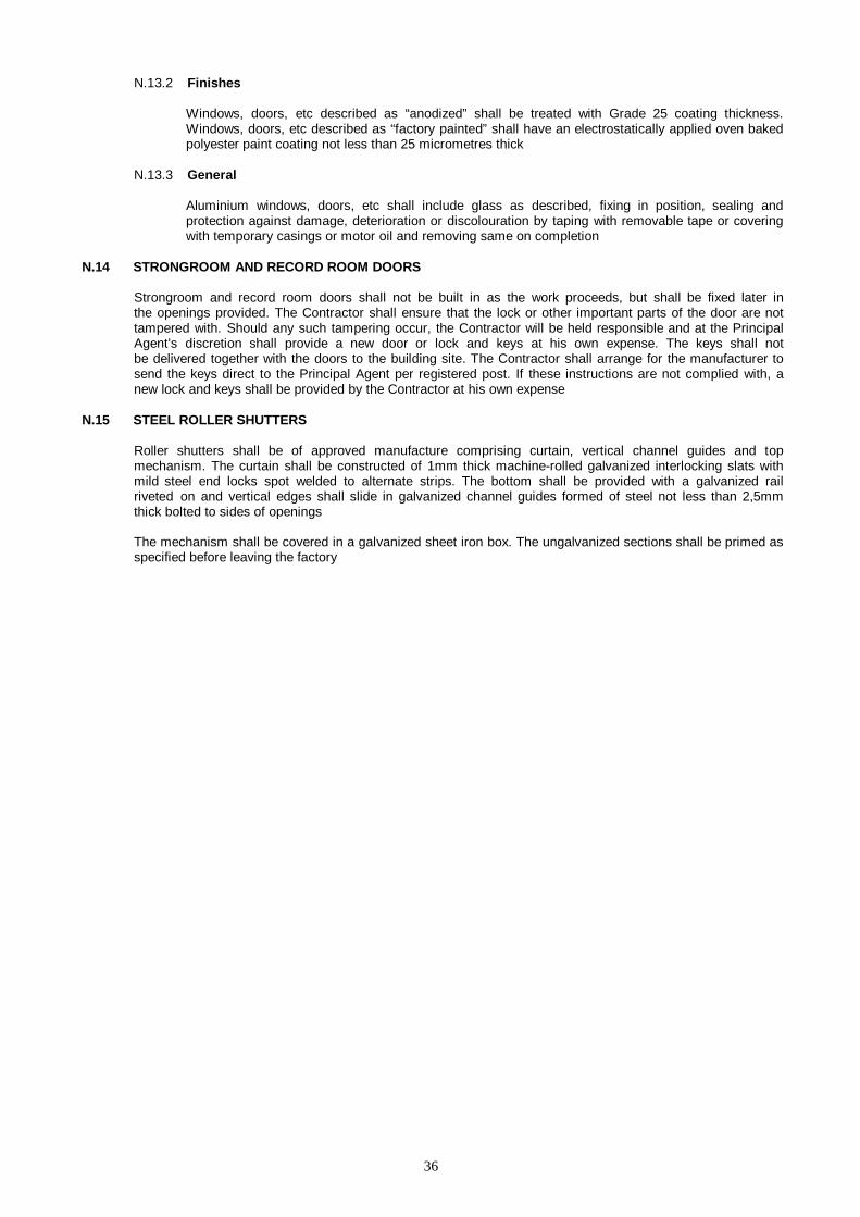
36
N.13.2 Finishes
Windows, doors, etc described as “anodized” shall be treated with Grade 25 coating thickness. Windows, doors, etc described as “factory painted” shall have an electrostatically applied oven baked polyester paint coating not less than 25 micrometres thick
N.13.3 General
Aluminium windows, doors, etc shall include glass as described, fixing in position, sealing and protection against damage, deterioration or discolouration by taping with removable tape or covering with temporary casings or motor oil and removing same on completion
N.14 STRONGROOM AND RECORD ROOM DOORS
Strongroom and record room doors shall not be built in as the work proceeds, but shall be fixed later in the openings provided. The Contractor shall ensure that the lock or other important parts of the door are not tampered with. Should any such tampering occur, the Contractor will be held responsible and at the Principal Agent’s discretion shall provide a new door or lock and keys at his own expense. The keys shall not be delivered together with the doors to the building site. The Contractor shall arrange for the manufacturer to send the keys direct to the Principal Agent per registered post. If these instructions are not complied with, a new lock and keys shall be provided by the Contractor at his own expense
N.15 STEEL ROLLER SHUTTERS
Roller shutters shall be of approved manufacture comprising curtain, vertical channel guides and top mechanism. The curtain shall be constructed of 1mm thick machine-rolled galvanized interlocking slats with mild steel end locks spot welded to alternate strips. The bottom shall be provided with a galvanized rail riveted on and vertical edges shall slide in galvanized channel guides formed of steel not less than 2,5mm thick bolted to sides of openings
The mechanism shall be covered in a galvanized sheet iron box. The ungalvanized sections shall be primed as specified before leaving the factory
37
O. PLASTERING
O.1 MATERIALS AND WORKMANSHIP
Materials and workmanship shall comply with the following standards:
Common cement SANS 50197-1(Class 32,5N)
Masonry cement SANS 50413-1(Class 225X)
Limes for use in building SANS 523 {Slaked (hydrated) limes}
Aggregates from natural sources – Fine aggregates for plaster and mortar SANS 1090
O.2 PREPARATORY WORK
Surfaces shall be clean and free of oil and thoroughly wetted directly before any plastering or other in situ finishes are commenced. Concrete surfaces shall be slushed with a mixture of one part cement and one part coarse sand or otherwise treated to form a proper key. Preparatory coats shall be thoroughly scored and roughened to form a proper key
O.3 FINISH
All coats of paving and plastering shall be executed in one operation without any blemishes
O.4 SCREEDS
Screeds shall be composed of one part cement and four parts sand
O.5 CEMENT RENDER
Cement render shall be composed of one part cement and three parts sand finished with a steel trowel to a smooth polished surface and cured for at least seven days after laying
Cement render finish shall be divided into panels not exceeding 6m2 with V-joints and deep trowel cuts
O.6 GRANOLITHIC
Granolithic shall be composed of one part cement, one part fine sand, two parts coarse sand and one part granite or other approved stone aggregate that will pass through a 5mm sieve, finished with a steel trowel to a smooth polished surface and cured for at least seven days after laying
Coloured granolithic shall be carried out in two coats in one operation and shall be tinted to the required colour with approved colouring pigment mixed into the finishing coat. Under no circumstances is the pigment to be sprinkled on and trowelled in after the granolithic is laid
Granolithic shall be divided into panels not exceeding 6m2 with V-joints and deep trowel cuts
O.7 TERRAZZO
Terrazzo shall be applied in two coats. The undercoat shall be composed of one part cement and three parts sand and shall be finished with a wooden float. The finishing coat shall be composed of one part cement and two parts marble or stone aggregate of a colour and size to obtain the required colour and texture and shall be at least 12mm thick, and applied before the undercoat has dried out. The finishing coat shall be compacted by tamping or rolling until superfluous water has been expelled, finished with a steel trowel and cured for at least seven days after laying. The finished surface shall show at least 80% of the aggregate
Surfaces described as “polished” shall be polished by machine using various grades of abrasive and grouting with tinted cement as necessary between polishings
Surfaces described as “polished” shall be polished by machine using various grades of abrasive and grouting with tinted cement as necessary between polishings

38
Surfaces described as “brushed” shall be brushed with a steel wire brush on the day the terrazzo has been laid to expose the aggregate as required
Where required, brass or other dividing strips shall be embedded in the undercoat to finish flush with the finished surface
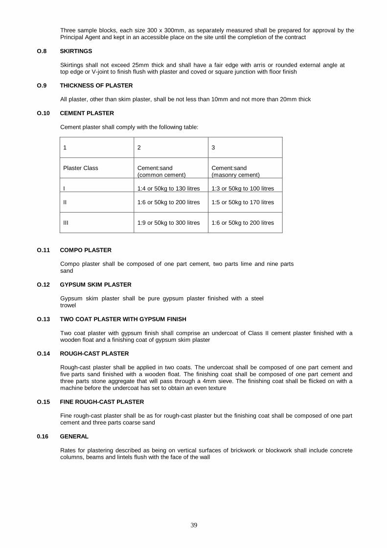
39
Three sample blocks, each size 300 x 300mm, as separately measured shall be prepared for approval by the Principal Agent and kept in an accessible place on the site until the completion of the contract
O.8 SKIRTINGS
Skirtings shall not exceed 25mm thick and shall have a fair edge with arris or rounded external angle at top edge or V-joint to finish flush with plaster and coved or square junction with floor finish
O.9 THICKNESS OF PLASTER
All plaster, other than skim plaster, shall be not less than 10mm and not more than 20mm thick
O.10 CEMENT PLASTER
Cement plaster shall comply with the following table:
1
2
3
Plaster Class
Cement:sand (common cement)
Cement:sand (masonry cement)
I
1:4 or 50kg to 130 litres
1:3 or 50kg to 100 litres
II
1:6 or 50kg to 200 litres
1:5 or 50kg to 170 litres
III
1:9 or 50kg to 300 litres
1:6 or 50kg to 200 litres
O.11 COMPO PLASTER
Compo plaster shall be composed of one part cement, two parts lime and nine parts sand
O.12 GYPSUM SKIM PLASTER
Gypsum skim plaster shall be pure gypsum plaster finished with a steel trowel
O.13 TWO COAT PLASTER WITH GYPSUM FINISH
Two coat plaster with gypsum finish shall comprise an undercoat of Class II cement plaster finished with a wooden float and a finishing coat of gypsum skim plaster
O.14 ROUGH-CAST PLASTER
Rough-cast plaster shall be applied in two coats. The undercoat shall be composed of one part cement and five parts sand finished with a wooden float. The finishing coat shall be composed of one part cement and three parts stone aggregate that will pass through a 4mm sieve. The finishing coat shall be flicked on with a machine before the undercoat has set to obtain an even texture
O.15 FINE ROUGH-CAST PLASTER
Fine rough-cast plaster shall be as for rough-cast plaster but the finishing coat shall be composed of one part cement and three parts coarse sand
0.16 GENERAL
Rates for plastering described as being on vertical surfaces of brickwork or blockwork shall include concrete columns, beams and lintels flush with the face of the wall
40
P. TILING
P.1 MATERIALS AND WORKMANSHIP
Materials and workmanship shall comply with the following
standards: Glazed ceramic wall tiles and fittings SANS 22
Ceramic wall and floor tiles SANS 1449
Common cement SANS 50197-1(Class
32,5N) Masonry cement SANS 50413-
1(Class 22,5X) Aggregates from natural sources – Fine aggregates for plaster and mortar SANS 1090
The design and installation of ceramic tiling SANS 10107
P.2 TILES, MOSAICS, ETC
Tiles, mosaics, etc shall be even in shape and size, free from cracks, twists or blemishes and uniform in colour
P.3 PREPARATORY WORK
Surfaces shall be clean and free of oil and thoroughly wetted directly before any tiling is commenced. Concrete surfaces shall be slushed with a mixture of one part cement and one part coarse sand or otherwise treated to form a proper key
P.4 CERAMIC WALL AND FLOOR TILING
Where tiles are fixed to plaster or screeds with an adhesive, the adhesive shall be as recommended by the manufacturer of the tiles. Joints shall be straight, continuous and flush pointed with an approved grouting compound
P.5 GENERAL
Tiling described as “on walls” is on brick walls or block walls unless otherwise stated and shall include concrete columns, beams and lintels flush with the face of the wall

41
Q. PLUMBING AND DRAINAGE
Q.1 MATERIALS AND WORKMANSHIP
Materials and workmanship shall comply with the following standards:
Sheet metal
Sheet zinc BS 849
Sheet aluminium BS 1470
Sheet copper BS 2870
Rainwater systems
Unplasticized poly(vinyl chloride) (PVC-U) components for external rainwater systems SANS 11
Pipes and fittings
Steel pipes : Pipes suitable for threading and of nominal size not exceeding 150mm SANS 62
Plain-ended solid drawn copper tubes for Potable water SANS 460
Malleable cast iron fittings threaded to ISO 7-1 SANS 4
Polyethylene (PE) pipes for water supply – Specifications SANS 4427
Cast iron fittings for asbestos cement pressure pipes SANS 546
Vitrified clay sewer pipes and fittings SANS 559
Reinforced concrete pressure pipes SANS 676
Concrete non-pressure pipes SANS 677
Cast iron pipes and pipe fittings for use above ground in drainage installations SANS 746
Unplasticized poly(vinyl chloride) (PVC-U) sewer and drain pipes and pipe fittings SANS 791
Fibre-cement pipes, couplings and fittings for sewerage, drainage and low-pressure irrigation SANS 819
Pitch-impregnated fibre pipes and fittings and jointing SANS 921
Unplasticized poly (vinyl chloride) (PVC-U) pressure pipe systems SANS 966-1
Unplasticized poly(vinyl chloride) (PVC-U) soil, waste and vent pipes and pipe fittings SANS 967
Rubber joint rings (non-cellular) SANS 974-1
Copper-based fittings for copper tubes SANS 1067-1&2
Fibre-cement pressure pipes and couplings SANS 1223
Polypropylene pressure pipes SANS 1315
Non-metallic waste traps SANS 1321-1&2
Vent valves for drainage installations SANS 1532
Heavy duty cast iron pipe fittings for drainage

42
and gas and water supplies BS 78
43
Lead pipes BS 602
Cast iron pressure pipes for use in drainage and gas and water supplies BS 1211
Stainless steel pipes for use with compression fittings BS 4127
Sanitary fittings etc
Stainless steel sinks with draining boards (for domestic use) SANS 242
Stainless steel wash-hand basins and wash troughs SANS 906
Stainless steel sinks for institutional use SANS 907
Stainless steel stall urinals SANS 924
Acrylic sanitary ware : Baths SANS 1402-1
Glazed ceramic sanitary ware SANS 497
WC flushing cisterns SANS 821
Flush valves for WC flushing cisterns SANS 1509
Taps, valves etc
Water taps (metallic bodies) SANS 226
Water taps (plastic bodies) SANS 1021
Single control mixer taps SANS 1480
Float valves SANS 752
Plastic floats for ball valves SANS 1006
Functional control valves and safety valves for Domestic hot and cold water supply systems SANS 198
Cast iron gate valves for waterworks SANS 664
Automatic shut-off flush valves for water closets and urinals SANS 1240
Check valves (flanged and wafer types) SANS 1551-1&2
Fire extinguishers
Portable refillable fire extinguishers SANS 1910
Portable rechargeble fire extinguishers : Halogenated hydrocarbon type extinguishers SANS 1151
Water heaters and fire hose reels
Fixed electric storage water heaters SANS 151
Fire hose reels (with semi-rigid hose) SANS 543
Drainage covers, gratings, etc
Cast iron surface boxes and manhole and inspection covers and frames SANS 558
Cast iron gratings for gullies and stormwater drains SANS 1115
The installation of polyethylene and poly (vinyl chloride) (PVC-U and PVC-M) pipes SANS 10112

44
Water supply and drainage for buildings SANS 10252-1&2
45
Cast iron step irons BS 1247
Q.2 GENERAL
Q.2.1 Excavations
Excavations shall be deemed to be in “earth”. Backfilling to excavations shall be executed in 300mm thick layers, watered and compacted. Surplus excavated material shall be spread and levelled over site as directed
Q.2.2 Concrete
Unreinforced concrete shall be Class B prescribed mix concrete and reinforced and precast concrete shall be Class C prescribed mix concrete
Q.2.3 Brickwork
Brickwork shall be of extra hard burnt bricks built in Class I mortar
Q.2.4 Plaster
Plaster shall be 1:3 cement plaster finished smooth with a steel trowel. All angles shall be rounded
Q.2.5 Diameters of pipes etc
Diameters stated for pipes, traps, valves, etc are internal diameters except PVC, polyethylene, stainless steel and copper pipes and traps for which external diameters are stated
Q.3 SHEET METAL WORK
Q.3.1 Galvanized sheet iron
Galvanized sheet iron shall be rolled steel sheet coated on both sides with Class Z275, unless otherwise specified, zinc coating complying with SANS 3575/4998. Sheets shall be free from white rust
Q.4 EAVES GUTTERS
Q.4.1 Galvanized sheet iron gutters
Galvanized sheet iron gutters shall have beaded edges and all joints shall be riveted and soldered. Angles shall be strengthened with 50 x 0,6mm galvanized sheet iron strips soldered on over the internal faces of mitres
Gutters shall be fixed with falls to outlets on 30 x 3mm galvanized mild steel brackets, bent to the shape of gutters, with front ends taken up to the underside of beaded edge of gutter and each screwed to roof timbers or bolted to fibre-cement fascias with 6mm galvanized gutter bolts. Gutters shall be bolted to brackets at front with 6mm galvanized gutter bolts, one to each bracket
Brackets shall be positioned at joints of gutters and intermediately at not exceeding 1,25m centres
Q.4.2 Fibre-cement gutters
Fibre-cement gutters shall have spigot and socket joints. Gutters shall be fixed with falls to outlets on standard aluminium alloy brackets, screwed or bolted to roof timbers or fascias
Q.4.3 Unplasticized polyvinyl chloride (UPVC) gutters
Gutters shall be fixed with falls to outlets on brackets as supplied by the manufacturer, screwed or bolted to roof timbers or fascias
Q.4.4 Aluminium gutters
Aluminium gutters shall be roll formed on site to required lengths and profiles from 3003H14-3SH4 alloy strip not less than 0,7mm thick factory coated on both sides with baked enamel and two coats of silicone modified polyester to a total minimum thickness of 20 micrometres. Angles, stopped

46
ends, etc shall be prefabricated units pop riveted to gutters with joints sealed with mastic. The guttering shall be in continuous lengths between angles, stopped ends, etc
47
Q.5 RAINWATER PIPES
Q.5.1 Galvanized sheet iron pipes
Galvanized sheet iron pipes shall have seams at the back and shall be jointed with soldered slip joints. Pipes shall be fixed to walls etc with galvanized mild steel holderbats spaced at not exceeding 2m centres with tails driven in or cut and pinned in 1:3 cement mortar
Q.5.2 Fibre-cement pipes
Fibre-cement pipes shall have spigot and socket joints. Pipes shall be fixed to walls etc with standard aluminium alloy holderbats with tails driven in or cut and pinned in 1:3 cement mortar
Q.5.3 Unplasticized polyvinyl chloride (UPVC) pipes
Pipes shall be fixed to walls etc with patented UPVC or aluminium clips and holderbats as supplied by the manufacturer of the pipe
Q.5.4 Aluminium pipes
Aluminium pipes and fixing straps shall be formed from 3003H14-3SH4 alloy strip not less than 0,7mm thick factory coated on both sides as described for aluminium gutters. Pipes shall be in continuous lengths with formed angles, offsets, shoes, etc. Pipes shall be fixed to walls etc with 20 x 0,6mm straps at not exceeding 1,5m centres screwed to 25 x 75 x 100mm hardwood chamfered and oiled blocks plugged to walls
Q.6 STORMWATER CHANNELS
In-situ concrete stormwater channels shall be constructed of unreinforced concrete with segmental channel formed in top. Channels shall be laid to falls on a well rammed earth bottom and finished smooth on exposed surfaces
Precast concrete channels shall be of 25 MPa concrete, generally in 1m lengths, finished smooth from the mould on exposed surfaces, laid to falls on a well rammed earth bottom, jointed in 1:3 cement mortar and pointed with keyed joints
48
Q.7 JOINTS
Joints of pipes not covered by SANS shall be as follows:
Pipes Joints
Fibre-cement, concrete, pitch-impregnated fibre and vitrified clay pipes for use under ground in non-pressure pipe lines
Flexible joints in accordance with the manufacturer’s instructions
Cast iron for use above ground
Spigot and socket joints with tarred rope yarn and caulking compound
or Plain ended joints with stainless steel couplings with neoprene rubber sleeves
Cast iron for use below ground Spigot and socket joints with tarred rope yarn and caulking compound
Galvanized mild steel Joints of screwed galvanized steel sockets or bolted galvanized iron flanges
Screwed joints with plastic jointing tape or hemp Flanged joints which shall be bolted and provided with rubber gaskets and with flanges screwed to pipes
Joints between pipes of different materials shall be as follows:
Between cast iron and mild steel Spigot and socket joints with tarred rope yarn and caulking compound
Between cast iron and clay Spigot and socket joint with semi-dry cement caulking and 1:2 cement mortar fillet
Between mild steel or copper and clay Spigot and socket joint with either bitumen or semi-dry cement caulking and 1:2 cement mortar fillet
Q.8 FIXING OF PIPES
Pipes shall be fixed as follows:
Q.8.1 Galvanized mild steel (except those stated in Q.8.3)
To walls with galvanized mild steel brackets for pipes not exceeding 80mm diameter and with galvanized cast iron hinged holderbats with brass pins or bolts for pipes exceeding 80mm diameter; both types with tails cut and pinned in To woodwork with screw-on type galvanized mild steel holderbats
Q.8.2 Copper and stainless steel To walls with brass holderbats or screw-on type two- piece spacing clips for pipes not exceeding 75mm diameter and with purpose made holderbats for pipes exceeding 75mm diameter; both types with tails cut and pinned in 1:3 cement mortar To woodwork with screw-on type brass holderbats
Q.8.3 Cast iron and galvanized mild steel for soil, waste and vent pipes
To walls with hinged cast iron holderbats with brass bolts and with tails cut and pinned in 1:3 cement mortar To woodwork with screw-on type galvanized mild steel holderbats
Q.8.4 Polyethylene, polypropylene and patented UPVC or unplasticized polyvinyl chloride
To walls, woodwork, etc with aluminium clips and holderbats as supplied by the manufacturer of the pipes
Q.8.5 Fibre-cement To walls with aluminium alloy holderbats with tails cut and pinned in 1:3 cement mortar
49
Q.8.6 Pipes fixed to ceilings Fixed with holderbats and standard or purpose made hangers, with extended hangers for pipes to falls
Q.9 PIPES LAID IN GROUND
Q.9.1 Water pipes etc
Water pipes, gas pipes, etc laid in ground shall be at least 400mm deep from the crown of the pipe to the finished surface
Q92 Drain pipes
Excavations taken out too deep shall be filled in with selected soil and compacted. Backfilling to sides and up to 300mm above plastic pipes shall be free from stone or hard substances which will not pass a 10mm mesh
Q.10 CLEANING EYE LIDS
Cleaning eye lids for drain pipe fittings shall be fixed and sealed as follows:
Pipe fittings Method of sealing and fixing
Fibre-cement Sealed with synthetic rubber or bituminous mastic packing and fixed with screws
Vitrified clay Polypropylene lid sealed with synthetic rubber packing and pressed into position
Polypropylene and unplasticized polyvinyl chloride Sealed with synthetic rubber packing
and screwed on or pressed into position
Cast iron Sealed with tallow or putty and fixed with non- ferrous metal screws
Galvanized malleable cast iron and cast brass Sealed with synthetic rubber packing
and screwed in
Q.11 CLEANING EYES
Cleaning eyes shall consist of cast iron frames and lids with letters “CE” (or “SO”) cast in lids. The lids shall be secured with non-ferrous metal screws. Frames shall be jointed to vertical drain pipes. Cleaning eyes shall be encased in unreinforced concrete taken up to ground level and plastered on exposed surfaces
Q.12 INSPECTION EYE MARKER SLABS
Inspection eye marker slabs shall be 350 x 350 x 50mm thick precast concrete finished smooth from the mould, with letters “IE” (or “IO”) formed in top and placed flush in ground or paving
Q.13 GULLEYS
Gulleys shall be built up of traps, vertical piping and gulley heads with loose gratings, all encased in unreinforced concrete to finish flush with gulley head top and taken up to at least 50mm above surrounding finished surfaces. The outer top edge of the concrete encasing shall be splayed and the exposed surfaces plastered
50
Q.14 DISHED GULLEYS
Dished gulleys shall be built up of traps, vertical piping and gulley heads with loose gratings, all encased in unreinforced concrete and with dished unreinforced concrete hopper size 450 x 450mm overall around gulley head with rounded kerb 50mm wide to front and sides and 25mm wide at back, 100mm high above top of dishing and the hopper plastered on exposed surfaces. Top of hopper shall be taken up to at least 50mm above surrounding finished surfaces
Q.15 SUMPS, CATCHPITS, INSPECTION CHAMBERS, ETC
Q.15.1 Rainwater sumps
Rainwater sumps shall be built with half-brick sides on 100mm thick unreinforced concrete bottom, plastered internally on walls and with 80mm high unreinforced concrete kerb at top rebated for grating or cover and plastered on exposed surfaces
Q.15.2 Stormwater catchpits and inspection chambers
Brick catchpits and inspection chambers shall be built with one-brick sides on 150mm thick unreinforced concrete bottom projecting 100mm beyond walls all round, plastered internally on walls and with 100mm thick reinforced concrete cover slab with opening rebated for frame of grating or cover and plastered on exposed surfaces
Precast concrete catchpits and inspection chambers shall be constructed in accordance with the applicable details shown on Drawing LE-1 of SANS 1200LE. Precast concrete manhole sections and slabs shall comply with SANS 1294 and pipes shall be SC type and in accordance with SANS 677
Q.15.3 Sewer inspection chambers
Brick inspection chambers shall be built as for brick stormwater inspection chambers and with the bottom of the chamber well benched around half round channels, bends, junctions, etc up to sides of chamber in unreinforced concrete finished smooth
Precast concrete inspection chambers shall be constructed in accordance with the applicable details shown on Drawing LD-5 of SANS 1200LD. Precast concrete manhole sections and slabs shall comply with SANS 1294 and the pipes shall be SC type in accordance with SANS 677
Q.15.4 Stormwater drain junction boxes
Junction boxes shall be formed of 150mm thick unreinforced concrete bottom and sides to suit the various sizes of the drain pipes and built after the pipes have been laid, with the sides taken up slightly higher than the highest pipe and finished level on top for and covered with a 75mm thick loose precast concrete slab
Q.15.5 Step irons
Where inspection chambers exceed 1,2m deep, cast iron step irons shall be provided, built into the wall at 300mm centres and staggered regularly in vertical rows spaced at 200mm centres horizontally
Q.16 STOPCOCK AND METER BOXES
Stopcock and meter boxes shall be built with half-brick sides with a cast iron box and lid complying with SANS 558 set in 75mm wide unreinforced concrete kerb for the full depth of the cast iron box and plastered on exposed surfaces
Q.17 VALVE CHAMBERS
Valve chambers shall be built with half-brick sides with 100mm thick unreinforced concrete kerb to top with rebate for cover and frame to finish flush with adjacent paving or finished ground level and plastered on exposed surfaces
Q.18 CAST IRON COVERS, GRATINGS, ETC
All cast iron covers, gratings, frames and surface boxes shall be coated with preservative solution. Frames shall be cast into concrete. Covers, except covers to stormwater drainage or electrical cable inspection chambers, shall be set in grease
Q.19 CONCRETE ENCASING

51
Concrete encasing for pipes, bends, traps, gulleys, grease traps, etc shall be unreinforced concrete not less than 100mm thick all round
52
Q.20 SANITARY FITTINGS
Q.20.1 General
Glazed ceramic, acrylic and porcelain enamelled sanitary fittings and component parts shall be white. Accessories for sanitary fittings shall be chromium plated brass
Waste outlets for baths, basins, etc shall comprise chromium plated brass waste union with grating, rubber washers and locknut, fitted with rubber or vulcanite plug on a chromium plated brass chain and stay
Q.20.2 Stainless steel sanitary fittings
Stainless steel sinks and draining boards, basins, wash troughs and urinals shall be AISI Type 304 satin finished stainless steel. All stainless steel fittings shall be treated on the back with a vermin proof sound deadening coating. Sinks, basins and wash troughs shall be provided with 40mm diameter screwed waste outlets
Q.20.3 Precast concrete wash troughs
Reinforced precast concrete wash troughs shall have a sloping front with ribbed rubbing surface and shall be finished smooth on exposed faces with top edges and inner angles rounded. Each compartment shall be fitted with a 40mm diameter waste outlet. Wash troughs shall each be supported on two reinforced precast concrete pedestals finished smooth on exposed faces
Q.20.4 Steel baths
Steel baths shall be porcelain enamelled internally and painted externally and fitted with waste outlet and overflow grating with coupling
Q.20.5 Acrylic resinous baths
Acrylic resinous baths shall be fitted with waste outlet and overflow grating with coupling
Q.20.6 Acrylic resinous wash hand basins
Acrylic resinous wash hand basins and vanity units shall have a smooth high gloss finish, with outlet openings, soap recesses, tap-holes and integral overflow and shall be fitted with waste outlet and overflow grating with coupling
Q.20.7 Glazed ceramic sanitary fittings
Sinks shall be provided with integral weir overflows
Washdown closet pans shall have washdown action and be provided with smooth finished injection moulded polypropylene heavy duty double flap seats fixed with non-ferrous bolts. Urinal channels shall be provided with outlet gratings fitted in bitumen
Q.20.8 Flush and sparge pipes
Flush pipes for high level cisterns shall be of plastic or drawn galvanized steel
Flushpipes for low level cisterns shall be of plastic
Flush and sparge pipes for urinals with high level cisterns shall be of chromium plated copper piping and of the sizes recommended by the manufacturer of the urinal
Q.21 INSTALLATION OF SANITARY FITTINGS
Sanitary fittings shall be installed as
follows: Q.21.1 Precast concrete wash
troughs
Precast concrete wash troughs shall be bedded on top of pedestals which shall be bedded on floors in

53
1:3 cement mortar
Q.21.2 Stainless steel wash troughs and wash hand basins
Stainless steel wash troughs and wash hand basins shall be fixed to walls on a pair of galvanized mild steel gallows brackets bolted to wall with 6mm diameter expanding bolts
54
Q.21.3 Acrylic resinous wash hand basins Acrylic resinous wash hand basins shall be fixed to walls on a pair of standard painted cast iron brackets screwed to underside of basin and bolted to wall with 6mm diameter expanding bolts
Q.21.4 Ceramic wash hand basins
Ceramic wash hand basins shall be fixed to walls on a pair of standard painted steel or cast iron brackets bolted to wall with 6mm diameter expanding bolts
Q.21.5 Acrylic resinous baths
Acrylic resinous baths shall be bedded in 1:5 cement mortar on three cross rows of bricks or bedded solid on a layer of dry river sand and fixed to wall with galvanized steel brackets under edges (in the middle of the sides against walls) bolted to wall with 6mm diameter expanding bolts and sealed along top against wall finishes with patent mildew resistant silicone rubber
Q.21.6 Washdown closet pans and cisterns
Washdown closet pans shall be bedded on floors in 1:3 cement mortar. Cisterns shall be fixed to walls with 6mm diameter expanding bolts
Q.21.7 Ceramic urinals
Ceramic stall and slab urinals shall be bedded on floors and against walls in 1:3 cement mortar. Slabs, channels, treads, etc shall be jointed in 1:3 cement mortar and pointed in white cement
Ceramic bowl urinals shall be fixed to walls on standard steel brackets bolted to wall with 6mm diameter expanding bolts. Cisterns shall be fixed to walls on standard brackets bolted to wall with 6mm diameter expanding bolts
Q.21.8 Stainless steel urinals
Stainless steel stall and slab urinals shall be bedded on floors in 1:3 cement mortar and with backs and sides against walls filled in with fine unreinforced concrete. Cisterns shall be fixed as cisterns for ceramic urinals
Q.22 FIRE HOSE REELS
Fire hose reels shall each be fitted with a 30m long hose of internal diameter not less than 19mm with a 4,8mm internal diameter chromium plated brass nozzle
Q.23 FIRE EXTINGUISHERS
All fire extinguishers shall be fully charged
Q.24 TESTS
Sewerage pipe lines, sanitary plumbing including fittings and hot and cold water supply and fire service shall be tested to the approval of the Principal Agent and Local Authority
The Contractor shall provide all testing apparatus, material and labour required for the tests and inspections
55
R. GLAZING
R.1
MATERIALS AND WORKMANSHIP
Materials and workmanship shall comply with the foll
owing standards:
Glass in building SANS 50572-1 to 5
Glazing putty for wooden and metal window frames SANS 680
Silvered glass mirrors for general use SANS 1236
Safety and security glazing materials for buildings SANS 1263-1 to 3
Sealing compounds for the building industry, one Component, silicone-rubber based
SANS 1305
The installation of glazing materials in buildings SANS 10137
Work on glass for glazing SANS 1817
R.2 PUTTY ETC
Glazing putty shall be Type I for wooden sashes and Type II for steel sashes. Putty for glazing to unpainted hardwood shall be tinted to match the colour of the wood
Back putty shall not exceed 3mm thick. Putty shall not be painted until it has formed a surface crust, and if the putty does not form a surface crust it shall be replaced
Butyl putty shall be used where glass is to be fixed in aluminium sashes with glazing beads
Non-setting compounds shall be used where laminated glass is fixed in sashes with glazing beads
56
S. PAINTWORK
S.1 MATERIALS AND WORKMANSHIP
Materials and workmanship shall comply with the following
standards: Decorative paint for interior use SANS 515
Decorative high gloss enamel paints SANS 630
Primers for wood (for external work) SANS 678
Primers for wood (for internal work) SANS 678
Zinc phosphate primer for steel SANS 1319
Undercoats for paints (except emulsion paint) SANS 681
Aluminium paint SANS 682
Varnish for interior use SANS 887
Emulsion paints SANS 1586
Materials for paintwork shall be delivered to the site in unopened containers and applied in accordance with the manufacturer’s instructions. Materials shall be suitable for application to the surfaces concerned. Undercoats shall be as recommended by the manufacturer of the finishing coats
S.2 PREPARATORY WORK
S.2.1 Plastered surfaces etc
Plastered surfaces shall be thoroughly inspected and, if necessary, washed down and brushed in order to remove any traces of efflorescence and allowed to dry completely before any paint finish is applied. Before any paint is applied, holes, cracks and irregularities in plaster and other surfaces shall be filled with a suitable filler and finished smooth. Unfinished concrete surfaces shall have all projections rubbed off and shall be thoroughly cleaned with a spirits-of-salts solution (1 part concentrated spirits- of-salts to 4 parts water)
S.2.2 Metal surfaces
Metal surfaces shall be sanded, where necessary, washed with a suitable cleaning agent and left smooth
Protective coatings applied by manufacturers to galvanized metal surfaces shall be removed with a suitable agent and the surfaces washed down
Rust, grease and defective factory primers on metal surfaces, as well as pitch on cast iron pipes, shall be removed
S.2.3 Wood surfaces
Knots in woodwork shall be treated with knotting. Minor blemishes shall be filled with a suitable filler. Wood surfaces shall be sanded smooth
S.3 APPLICATION OF PAINT
Primers to wood surfaces shall be applied by brush. Primers to other surfaces may be applied by roller with the approval of the Principal Agent. Undercoats and finishing coats may be applied by brush or roller

57
Paint shall not be sprayed on except in the case of cellulose and other special paints where spray painting is the accepted method of application
Before subsequent coats of paint are applied the previous coat shall be properly dry and shall be sanded down where necessary

58
S.4 COLOUR SCHEME
A colour scheme comprising colours and the blending of colours approved by the Principal Agent shall be used for the paintwork. The tints of the undercoats shall closely match the finishing coat but nevertheless differ sufficiently to indicate the number of undercoats. Colour samples of the finishing coats shall be provided in all cases
S.5 GENERAL
Paintwork shall include the preparation of surfaces, filling, stopping, sanding and priming of nail heads and screws. Where windows, sashes, etc are to be painted, the rebates of the openings to be glazed shall be primed

59
T. PAPERHANGING
T.1 PREPARATORY WORK
Plaster surfaces to be papered shall be dry, thoroughly cleaned down, filled with a suitable filler as necessary to obtain a smooth surface and painted thereafter with a single coat of emulsion paint
Wood surfaces to be papered shall be knotted, stopped and sanded
T.2 PAPERHANGING
Wallpaper shall be hung in vertical long lengths. Vertical joints shall be close-fitted and plumb and the paper shall be tightly fitted to skirtings, ceilings, door frames, windows, etc. Horizontal joints will not be allowed
60
U. EXTERNAL WORKS
U.1 GENERAL
U.1.1 Excavations
Excavations shall be deemed to be in “earth”
U.2 LANDSCAPING
U.2.1 Topsoil
Topsoil shall vary between sandy loamy soil and sandy clayey soil with an ideal composition of 15% to 25% clay, 10% silt/sludge and 65% to 75% sand, with a minimum ratio of organic material of 2%. All material shall be free of harmful deposits as well as unwanted seeds
U.2.2 Compost
Compost shall be composed of properly decayed organic material, free from harmful deposits, salts, seeds and other waste material and shall have a pH of more than 4 and less than 7
U.2.3 Mulch
Mulch shall be approved organic material free from small particles of bark residue, fungus, disease, etc
U.2.4 Lime
Lime shall be agricultural lime of an approved manufacture
U.2.5 Fertilizer
Fertilizer shall be of the type specified, mixed thoroughly into the soil as prescribed. No fertilizer shall be added more than two weeks prior to planting
U.2.6 Backfilling
Backfilling in plant and tree holes shall be composed of two parts topsoil to one part compost mixed thoroughly together and compacted by foot in 100mm layers. Fertilizer shall only be added if pre- scribed
U.2.7 Pebbles
Pebbles shall be smooth with a uniform colour and form and ranging in size from 50mm to 75mm diameter. Removal of pebbles from river beds shall be done selectively to avoid any major disruption to the ecology of the river and environment
U.2.8 Plant material
U.2.8.1 General
All plant material (plants, shrubs, trees, etc) shall be obtained from a registered nursery and shall be free from damaged parts, parasites, fungus, other plant diseases or insects. No container-bound plants will be acceptable
U.2.8.2 Trees
The height of trees described in the bills of quantities shall be measured from the top of the root ball to the top of the tree. Where trees are pruned, such prune wounds shall not be more than 25mm in diameter and be sealed with an approved sealing compound
U.2.8.3 Shrubs and small plants
Shrubs and small plants shall meet the requirements for height and spread as specified. Thin or sparsely branched plants shall not be accepted. Branches shall be well spread with ample young branches and the plant as a whole shall be growing well

61
U.2.8.4 Groundcover
Groundcover shall be dense and healthy and shall comply with the minimum requirements for leaf density as specified
62
Formal grass shall be planted as runners in 50mm deep drills at 150mm centres unless otherwise described
U.2.9 Cultivation and preparation of planting areas etc
All surface rocks and stones larger than 50mm shall be removed before commencing cultivation and preparation. The entire area shall be ripped and rotavated using approved machinery by breaking up the earth to a depth of 300mm at 600mm centres in both directions, unless otherwise described, and then levelled. Where fertilizer or compost is specified, it shall be worked into the topsoil after ripping and rotavation to a depth of 300mm and finished to final levels
All fertilizer to areas to be grassed shall be strewn on the final layer before final finishing is commenced and worked mechanically into the top 150mm soil
U.2.10 Planting procedure
Holes for shrubs and groundcover shall be as follows:
Shrubs – 500 x 500 x 500mm deep
Groundcover – 300 x 300 x 300mm deep (if not planted in drills)
Holes for trees shall be square, of adequate size to accommodate the root system and suitable for the height of the tree
All plant material shall be watered thoroughly before careful removal from the container and planted in the prescribed planting medium with the top of the soil in the container finishing level with the surrounding area. Water dams size 800mm diameter x 150mm deep and 500mm diameter x 150mm deep shall be formed around trees and shrubs respectively and all planting material shall be watered immediately after planting. Trees, shrubs, etc shall be properly staked or stayed, depending on their size, on the prevailing windy side with patent tree ties
U.2.11 Maintenance
All planted areas shall be maintained for a period of three months after practical completion as defined in the contract with the exception of hydroseeded areas which shall be maintained for 12 months after an acceptable cover has been obtained
This maintenance shall consist of keeping clear of weeds and litter, loosening soil where necessary every two weeks, replacing damaged, diseased or dead plants, pruning, cutting and mowing as neces- sary and watering so as to keep the plant material in a healthy growing condition
U.3 ROADWORK
U.3.1 Filling
Filling under roads etc shall be of inert material having a maximum plasticity index of 10, free from large stones etc spread, levelled, watered and compacted in layers not exceeding 200mm thick to a density of 98% Mod AASHTO
U.3.2 Preparation of sub-grade
The sub-grade shall be prepared by scarifying for a depth of 150mm and compacting to a density of 98% Mod. AASHTO, including trimming to the correct levels and grades
U.3.3 Base course
The base course shall consist of crusher run stone compacted to a density of 98% Mod. AASHTO and finished to the correct levels and grades
U.3.4 Weed killer
The completed sub-grade shall be treated with an approved total weed killer
U.3.5 Bituminous premix road surfacing

63
Before spreading the premix material, the base course shall be swept clean and free from all dust, dirt and loose particles, lightly wetted and sprayed with a prime coat of cutback bitumen complying with SANS 308 at the rate of 1 litre/m2
The material shall consist of semi-gap graded crushed stone aggregate having the following grading:
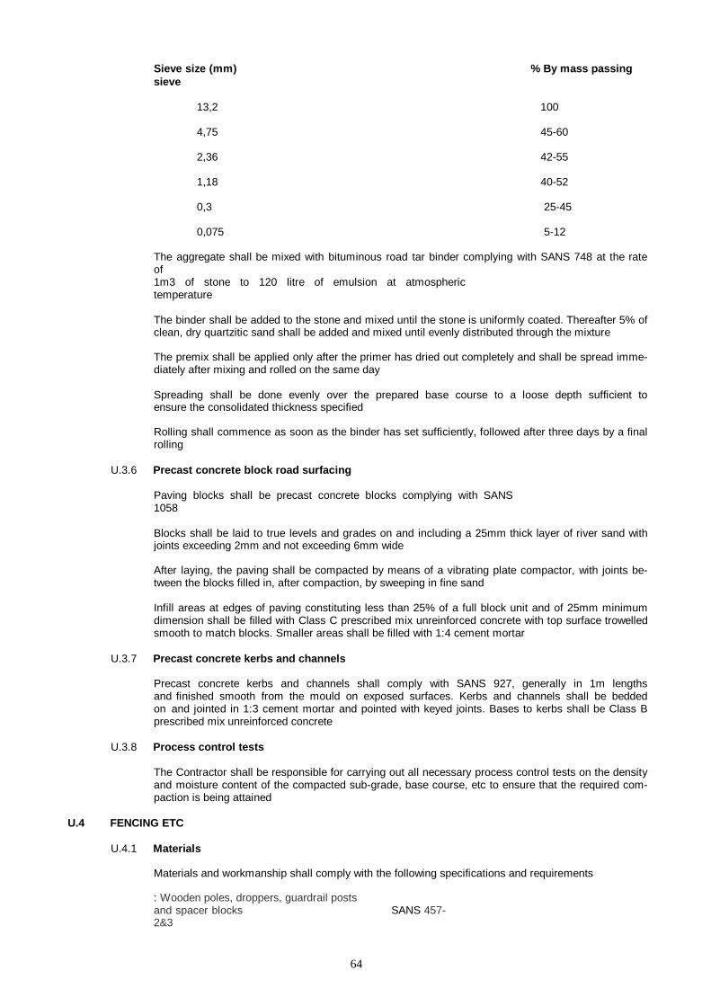
64
Sieve size (mm) % By mass passing sieve
13,2 100
4,75 45-60
2,36 42-55
1,18 40-52
0,3 25-45
0,075 5-12
The aggregate shall be mixed with bituminous road tar binder complying with SANS 748 at the rate of 1m3 of stone to 120 litre of emulsion at atmospheric temperature
The binder shall be added to the stone and mixed until the stone is uniformly coated. Thereafter 5% of clean, dry quartzitic sand shall be added and mixed until evenly distributed through the mixture
The premix shall be applied only after the primer has dried out completely and shall be spread imme- diately after mixing and rolled on the same day
Spreading shall be done evenly over the prepared base course to a loose depth sufficient to ensure the consolidated thickness specified
Rolling shall commence as soon as the binder has set sufficiently, followed after three days by a final rolling
U.3.6 Precast concrete block road surfacing
Paving blocks shall be precast concrete blocks complying with SANS 1058
Blocks shall be laid to true levels and grades on and including a 25mm thick layer of river sand with joints exceeding 2mm and not exceeding 6mm wide
After laying, the paving shall be compacted by means of a vibrating plate compactor, with joints be- tween the blocks filled in, after compaction, by sweeping in fine sand
Infill areas at edges of paving constituting less than 25% of a full block unit and of 25mm minimum dimension shall be filled with Class C prescribed mix unreinforced concrete with top surface trowelled smooth to match blocks. Smaller areas shall be filled with 1:4 cement mortar
U.3.7 Precast concrete kerbs and channels
Precast concrete kerbs and channels shall comply with SANS 927, generally in 1m lengths and finished smooth from the mould on exposed surfaces. Kerbs and channels shall be bedded on and jointed in 1:3 cement mortar and pointed with keyed joints. Bases to kerbs shall be Class B prescribed mix unreinforced concrete
U.3.8 Process control tests
The Contractor shall be responsible for carrying out all necessary process control tests on the density and moisture content of the compacted sub-grade, base course, etc to ensure that the required com- paction is being attained
U.4 FENCING ETC
U.4.1 Materials
Materials and workmanship shall comply with the following specifications and requirements
: Wooden poles, droppers, guardrail posts and spacer blocks SANS 457-2&3

65
Zinc-coated fencing wire SANS 675
Prefabricated concrete components for fencing SANS 1372
Chain-link fencing and its wire accessories SANS 1373
66
Fasteners SANS 1700
Anti-intruder fences CKS 451
Metal droppers and standards CKS 451
U.4.2 Galvanized wire
All galvanized wire shall be zinc coated wire with Class B zinc coating. Straining wire shall be 4mm diameter galvanized mild steel wire. Tie wire shall be 1,6mm diameter galvanized mild steel wire
U.4.3 Plastic coated wire
Plastic coated straining wire shall be 3,15mm diameter Class C galvanized mild steel wire plastic coat- ed to an overall diameter of 3,95mm
Plastic coated tie wire shall be 1,8mm diameter Class C galvanized mild steel wire plastic coated to an overall diameter of 2,5mm
U.4.4 Galvanized barbed wire
Galvanized barbed wire shall be 2,5mm diameter mild steel double strand reverse twist zinc coated barbed wire with Class A zinc coating
U.4.5 Galvanized wire mesh
Galvanized wire mesh shall be 50mm mesh chain link netting of 2,5mm diameter Class C galvanized mild steel wire
U.4.6 Plastic coated wire mesh
Plastic coated wire mesh shall be 50mm mesh chain link netting of 2,5mm diameter Class C galva- nized mild steel wire plastic coated to an overall diameter of 3,25mm
U.4.7 Galvanized welded wire mesh
Galvanized welded wire mesh shall be fabricated from pre-galvanized wires to rectangular pattern welded together at each intersection using a welding method which forms a zinc oxide protective coat- ing at each intersection
U.4.8 Razor wire
Razor wire shall be fabricated from 2,5mm diameter galvanized high tensile steel wire fitted with razor barbs formed of 0,5mm galvanized steel strip clipped on at 37,5mm centres
U.4.9 Metal droppers and standards
Droppers shall be of ridged T-section mild steel with a mass of not less than 0,55kg/m. Standards shall be of I- section mild steel with a mass of not less than 3kg/m or of ridged edge Y-section mild steel with a mass of not less than 2,5kg/m, and shall be driven 600mm deep into the ground
Droppers and standards shall have either galvanized, sprayed metal or painted finish as described in the items and in accordance with CKS 451. In addition, those surfaces of standards embedded in the ground shall be coated with bitumen
U.4.10 Metal posts and stays
Posts and stays shall comply with CKS 451 and shall be of black galvanized mild steel tubing as speci- fied
Straining posts shall be of 108mm outside diameter x 3mm wall thickness tubing, each with a 300 x 300 x 5mm thick mild steel sole plate and a steel cap welded on
Intermediate posts shall be of 50mm outside diameter x 2,5mm wall thickness tubing, each with a 230 x 230 x 5mm thick mild steel sole plate and a steel cap welded on

67
Stays for straining posts shall be of 50mm outside diameter x 2,5mm wall thickness tubing, each with a 230 x 230 x 5mm thick mild steel sole plate welded on and fixed raking with top end flattened, bent, holed and bolted to straining post with and including a 5mm diameter galvanized mild steel bolt with nut and washer
Posts and stays shall have either galvanized or painted finish as described in the items and in accor- dance with CKS 451. In addition, sole plates and portions of posts and stays embedded in ground shall be coated with bitumen
4.68
68
U.4.11 Timber posts, stays and droppers
Timber posts shall be 125mm diameter, timber stays shall be 100mm diameter and timber droppers shall be 30mm diameter
U.4.12 Prestressed concrete posts and stays
Prestressed concrete posts and stays shall be finished smooth from the mould and uniformly stressed by means of high tensile longitudinal prestressing wires with concrete cover to wires of not less than 20mm
Corner and straining posts shall be 100 x 100mm and intermediate posts and stays shall be 75 x 75mm. Stays shall be fixed raking with top end splayed and glued to posts with a suitable epoxy compound
U.4.13 Bolts, nuts and washers
Straining eye bolts, hinge bolts, bolts, nuts and washers shall be galvanized
U.4.14 Precast concrete fencing
Precast concrete fencing over sloping terrain shall be stepped to suit terrain, including the use of in- creased lengths of posts as necessary, excavation, etc
U.4.15 Concrete bases
Bases in ground for posts, stays, etc shall be of Class B prescribed mix concrete with tops 100mm below surface of ground
Sizes of concrete bases for posts, stays, etc shall be as follows:
Straining and gate posts – 450 x 450 x 700mm
deep Intermediate posts – 300 x 300 x
600mm deep Stays – 600 x
300 x 500mm deep
U.4.16 Security overhangs
Where fencing is described as having a security overhang, the posts and standards shall have angular (single arm) extension arms
Extension arms shall be attached to the posts and standards by welding in the case of steel and by spiking in the case of timber
Concrete extension arms shall be cast integrally with the post or standard
Barbed wire to security overhangs shall be tightly strained and wired at each intersection with exten- sion arms and shall have barbed wire braces at 450mm centres between standards, posts, etc wired onto the barbed wire and the top straining wire
U.4.17 Gates
Gates shall be formed of 40mm outside diameter x 2,5mm wall thickness mild steel tubular framework with welded joints, strongly braced as necessary and filled in with wire mesh as described above, prop- erly strained and securely bound to framework with tie wire