
INVITATION FOR BIDS (IFB) HIGH COMMISSION OF INDIA …
100
INVITATION FOR BIDS (IFB) HIGH COMMISSION OF INDIA Grant Number: Col/DC/228/3/2011 Grant Name: Construction of Rabindranath Tagore Memorial Auditorium at University of Ruhuna Bid No Description of Work Estimated Cost /(Rs in millions) Contract Period Required Grade Col/DC/228/3/2011 Construction of Rabindranath Tagore Memorial Auditorium at University of Ruhuna 295 (Excluding VAT) 18 months C1 (Buildings) 1. Government of India has approved a grant for “Construction of Rabindranath Tagore Memorial Auditorium at University of Ruhuna” with the floor area of approximately 3000 sqm. 2. High Commission of India on behalf of Government of India now invites sealed bids from eligible and qualified bidders for construction of the above under National Competitive Bidding procedure. 3. The technical bid (Original & Duplicate) and the financial bid (Original & Duplicate) documents should be sealed by the bidder in separate covers duly superscribed and these four sealed covers are to be put in a bigger cover which should also be sealed and dully superscribed. 4. To be eligible for contract award, the successful bidder shall not have been blacklisted and shall meet the requirements of ICTAD registration as above or its equivalent. 5. Qualification requirements are indicated in the Bidding document. Additional details are provided in the Bidding Data & Contract Data. 6. The Bidding Document can be seen on Mission’s website www.hcicolombo.org . 7. A complete set of Bidding Document in English language may be purchased by interested bidders from the Project Officer (Development Cooperation), High Commission of India, 36-38, Galle Road, Colombo-03 from 05 August 2015 to 24August 2015 between 09:30 hrs and 16.00 hrs, upon payment of a non-refundable fee of Rs.10,000.00. The payment should be made by cash. 8. Bids shall be delivered by hand to the Project Officer (Development Cooperation), High Commission of India, 36-38, Galle Road, Colombo-03 on or before 15:00 hrs on 04 September 2015. Late bids will be rejected. Technical bids will be opened at 15:30 hrs on 04 September 2015 at the High Commission of India in the presence of the bidders’ representatives. 9. Pre-Bid conference will be held at the Conference Hall, High Commission of India, 36- 38, Galle Road, Colombo-03 at 1500 Hrs on 19 August 2015. 10. Each bidder shall provide the name and contact details of an individual to act as a point of contact during the tender process. That person may be asked to clarify the bid to provide additional information if required. 11. Clarification shall be issued to all bidders as corrigendum. 12. Only communications that are in writing from the High Commission of India, Colombo shall be considered as properly authorized expressions on the Mission’s behalf. 13. In submitting a bid to the High Commission of India, the bidder will be deemed to have understood this bidding document, obtained all requisite information and verified the correctness of any information to be relied upon.
Transcript of INVITATION FOR BIDS (IFB) HIGH COMMISSION OF INDIA …

INVITATION FOR BIDS (IFB) HIGH COMMISSION OF INDIA
Grant Number: Col/DC/228/3/2011
Grant Name: Construction of Rabindranath Tagore Memorial Auditorium at
University of Ruhuna
Bid No Description of Work Estimated Cost
/(Rs in millions)
Contract
Period
Required
Grade
Col/DC/228/3/2011
Construction of Rabindranath
Tagore Memorial Auditorium
at University of Ruhuna
295
(Excluding VAT) 18 months
C1
(Buildings)
1. Government of India has approved a grant for “Construction of Rabindranath Tagore
Memorial Auditorium at University of Ruhuna” with the floor area of approximately
3000 sqm.
2. High Commission of India on behalf of Government of India now invites sealed bids
from eligible and qualified bidders for construction of the above under National
Competitive Bidding procedure.
3. The technical bid (Original & Duplicate) and the financial bid (Original & Duplicate)
documents should be sealed by the bidder in separate covers duly superscribed and
these four sealed covers are to be put in a bigger cover which should also be sealed and
dully superscribed.
4. To be eligible for contract award, the successful bidder shall not have been blacklisted
and shall meet the requirements of ICTAD registration as above or its equivalent.
5. Qualification requirements are indicated in the Bidding document. Additional details
are provided in the Bidding Data & Contract Data.
6. The Bidding Document can be seen on Mission’s website www.hcicolombo.org.
7. A complete set of Bidding Document in English language may be purchased by
interested bidders from the Project Officer (Development Cooperation), High
Commission of India, 36-38, Galle Road, Colombo-03 from 05 August 2015 to
24August 2015 between 09:30 hrs and 16.00 hrs, upon payment of a non-refundable fee
of Rs.10,000.00. The payment should be made by cash.
8. Bids shall be delivered by hand to the Project Officer (Development Cooperation),
High Commission of India, 36-38, Galle Road, Colombo-03 on or before 15:00 hrs on
04 September 2015. Late bids will be rejected. Technical bids will be opened at 15:30
hrs on 04 September 2015 at the High Commission of India in the presence of the
bidders’ representatives.
9. Pre-Bid conference will be held at the Conference Hall, High Commission of India, 36-
38, Galle Road, Colombo-03 at 1500 Hrs on 19 August 2015.
10. Each bidder shall provide the name and contact details of an individual to act as a
point of contact during the tender process. That person may be asked to clarify the bid
to provide additional information if required.
11. Clarification shall be issued to all bidders as corrigendum.
12. Only communications that are in writing from the High Commission of India,
Colombo shall be considered as properly authorized expressions on the Mission’s
behalf.
13. In submitting a bid to the High Commission of India, the bidder will be deemed to
have understood this bidding document, obtained all requisite information and
verified the correctness of any information to be relied upon.

14. In submitting a bid to the High Commission of India, the bidder will be deemed to be
fully informed and to have accepted the terms and conditions outlined in this bid
document.
15. The bidding company and its sister company or subsidiary should not bid separately
in the same bid. A certificate to this effect should be given by the bidding company at
the time of bidding.
16. The decision of High Commission of India in deciding the eligibility of the company
to take part in the tender process is final.
17. The High Commission of India reserves the right to accept or reject any or all Bid(s)
and to annul the bidding process, at any time, thereby rejecting all bids, prior to any
Contract being awarded.
18. The High Commission of India, Colombo reserves the right to clarify without
restriction with bidders on any matter contained in the bids, without disclosing this to
any other person.
19. The bidders should note that in the event of Contract having been awarded, the
contractor will not assign in whole or in part its rights or obligations without the prior
approval of the High Commission of India.
20. The contract will also include provisions for the bidding company to adhere to all
local laws applicable. The contract will also include provisions of Force Majeure,
termination of contract, consequences of termination and re-tendering after
termination of contract.
21. Any dispute or difference regarding the interpretation of the provisions of the
Agreement/Contract shall be resolved amicably between the parties. If the dispute is
not resolved through mutual consultations within a period of six months, either party
may refer the dispute to arbitration in accordance with the Arbitration & Conciliation
Act 1996 of India as amended from time to time. The number of arbitrators shall be
one and that the place of arbitration shall be New Delhi, India. In such a situation the
applicable law will be the law of India. The language of the Tribunal shall be English.
The cost shall be borne by the parties equally unless otherwise determined by the
Arbitral Tribunal.
22. The Bids shall be valid for 150 days from the date of closing of bids or any extended
period. All bids shall be accompanied by a Bid Security as Clause 17.1 of the Bidding
Data.
Second Secretary (Development Cooperation)
High Commission of India,
36-38, Galle Road,
Colombo-03

INSTRUCTIONS TO BIDDERS
Instructions to Bidders applicable to this contract are those given in Section
1 of the Standard Bidding Document for Procurement of Works, ICTAD
Publication No. ICTAD/SBD/02, January 2007, published by the Institute
for Construction Training and Development (ICTAD).
Instruction to bidders shall be read in conjunction with the Bidding Data
provided under Section 2 of the Bidding Document

BIDDING DATABIDDING DATABIDDING DATABIDDING DATA

Bidding Data
Instructions
to Bidders
Clause Reference
(1.1) The Employer is
Name: Second Secretary (Development Cooperation)
Address: High Commission of India
36-38, Galle Road,
Colombo-03
The Employer’s representative:
Name: Vice Chancellor,.
Address: University of Ruhuna
Wellamadama
Matara
The Works consist of Construction of 1500 seats Auditorium
including civil works and specialized works and having floor area
of 3000 sqm (approx.) as shown in the drawings and described in
the BOQ.
(1.2) Intended Completion Date is 18 months from the Commencement
Date.
(2.1) The source of funds is Government of India
(3.1) The registration required:
Specialty : Building Construction
Grade : C1
(4.1) The following information shall be provided in Section 9 Schedules
∗ ICTAD Registration
Registration No: …………………
Grade :………………….
Specialty :………………….
Expiry Date :………………….
∗ NCASL member ship
Number :………………….
Expiry Date :………………….
∗ VAT Registration Number
∗ Construction Program
∗ Legal Status (Sole proprietor, Partnership, company, etc.)
∗ Authentication for signatory
∗ Total monetary Value of Building construction works
performed in last 5 years

∗ Experience in works of a similar nature & size for each of
the last five years.
∗ Major items of construction equipment proposed
∗ Qualification and experience of key staff
In addition to above the Bidders shall furnish the following information:
∗ Audited statements of accounts for last three years
∗ Value of work in hand
∗ Cash flow forecasting statement
∗ Arbitration/Litigation history
∗ Method Statement (The bidders shall submit a complete
method statement indicating the proposed methods and
procedures of; (a) site access and layouts (b) excavation / earth
retention (c) dewatering and disposal of water (d) erection of
formwork (e) production / supply of concrete (f) placing of
concrete (g) erection of roofs (h) filling works (j) transport /
hoisting of materials (k) controlling noise and dust (l) water
and electricity for the works (m) labour / material / plant hiring
and accommodation etc.
(4.2) The qualification criteria is as follows:
(a) Average annual volume of construction work performed in a last
five (5) years.
Average annual volume of construction work performed in a last five
(5) years shall be at least Rs . 300 million
(b) Deleted sub clause 4.2(b) and added following
Experience as prime contractor in the construction of at least one
contract of over 300 million in similar nature and complexity
equivalent to the Works over the last 5 years (to comply with this
requirement, works cited should be at least 70% completed).
(c) Essential Equipment
Proposals for the timely acquisition (Own, Lease, Hire etc.) of the
following essential equipment shall be:
Type Capacity (minimum)
1. Truck Mixer 6.0 m3
2. Mobile Crane 20 Ton
3. Hoist 05 Ton
4. Generator 250 kVA
5. Concrete mixer 10/7
6. Concrete pump car 55m3/Hr
……………………………..
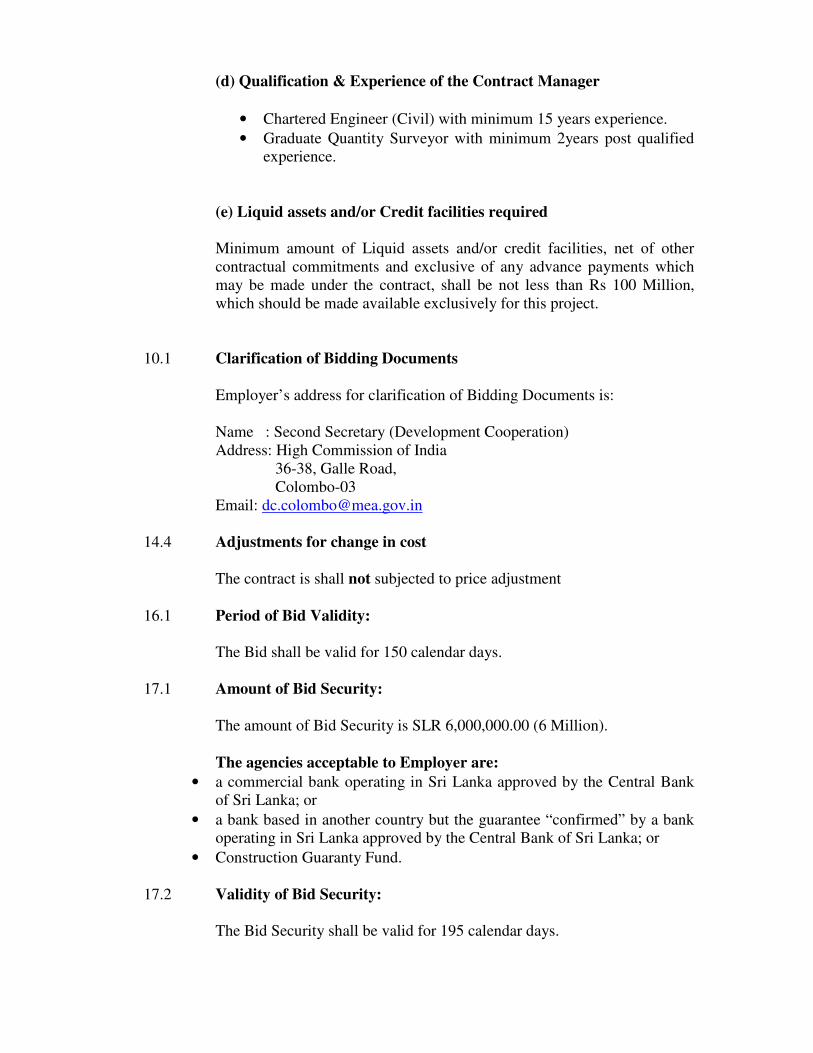
(d) Qualification & Experience of the Contract Manager
• Chartered Engineer (Civil) with minimum 15 years experience.
• Graduate Quantity Surveyor with minimum 2years post qualified
experience.
(e) Liquid assets and/or Credit facilities required
Minimum amount of Liquid assets and/or credit facilities, net of other
contractual commitments and exclusive of any advance payments which
may be made under the contract, shall be not less than Rs 100 Million,
which should be made available exclusively for this project.
10.1 Clarification of Bidding Documents
Employer’s address for clarification of Bidding Documents is:
Name : Second Secretary (Development Cooperation)
Address: High Commission of India
36-38, Galle Road,
Colombo-03
Email: [email protected]
14.4 Adjustments for change in cost
The contract is shall not subjected to price adjustment
16.1 Period of Bid Validity:
The Bid shall be valid for 150 calendar days.
17.1 Amount of Bid Security:
The amount of Bid Security is SLR 6,000,000.00 (6 Million).
The agencies acceptable to Employer are:
• a commercial bank operating in Sri Lanka approved by the Central Bank
of Sri Lanka; or
• a bank based in another country but the guarantee “confirmed” by a bank
operating in Sri Lanka approved by the Central Bank of Sri Lanka; or
• Construction Guaranty Fund.
17.2 Validity of Bid Security:
The Bid Security shall be valid for 195 calendar days.

19.1 Pre Bid Meeting
Pre bid meeting – Venue: Conference Hall
High Commission of India
36-38, Galle Road,
Colombo-03
Date 19 August 2015 Time 1500 hrs
21.2 (a) The Employer’s address for the purpose of Bid submission
The Employer’s address for the purpose of Bid submission is;
Second Secretary (Development Cooperation)
High Commission of India
36-38, Galle Road,
Colombo-03
21.2 (b) Identification Number for Contract
Identification Number for Contract is Col/DC/228/3/2011
22.1 Deadline for submission of Bids
The deadline for submission of Bids shall be 1500 hrs on 4 September
2015 at High Commission of India, 36-38, Galle Road,Colombo-03
25.1 Bid Opening
Bids will be open 1530 hrs 4 September 2015 at High Commission of
India, 36-38, Galle Road,Colombo-03
35.1 Amount of Performance Security
The amount of Performance Security is ten percent (10%) of the Initial
Contract Price and shall be valid up to 60 days beyond the intended
completion date.
Performance Security shall be issued by an agency acceptable to
Employer using the form for Performance Security (unconditional
guarantee) included in Standard Forms and it shall be in favour of High
Commission of India.
The agencies acceptable to Employer are:
• a commercial bank operating in Sri Lanka approved by the Central
Bank of Sri Lanka; or
• a bank based in another country but the guarantee “confirmed” by
a bank operating in Sri Lanka approved by the Central Bank of Sri
Lanka; or
• Construction Guaranty Fund.

37 Adjudicator proposed by The Employer
Any dispute or difference regarding the interpretation of the
provisions of the Agreement/Contract shall be resolved amicably
between the parties. If the dispute is not resolved through mutual
consultations within a period of six months, either party may refer
the dispute to arbitration in accordance with the Arbitration &
Conciliation Act 1996 of India as amended from time to time. The
number of arbitrators shall be one and that the place of arbitration
shall be New Delhi, India. In such a situation the applicable law
will be the law of India. The language of the Tribunal shall be
English. The cost shall be borne by the parties equally unless
otherwise determined by the Arbitral Tribunal

CONDITIONS OF CONTRACT
Conditions of Contract that will be applicable for this Contract are that given
in section 3 of the Standard Bidding Document for Procurement of Works,
ICTAD Publication No. ICTAD/SBD/02, January 2007, published by the
Institute for Construction Training And Development (ICTAD).
Condition of Contract shall be read in conjunction with Contract Data
provided under Section 4 of the Bidding Document

CONTRACT DATACONTRACT DATACONTRACT DATACONTRACT DATA

CONTRACT DATA
Conditions of
Contract Clause
Number/s
1.1.2.2. & 1.3 Employer is
Name: Second Secretary (Development Cooperation)
Address: High Commission of India
36-38, Galle Road,
Colombo-03
The Employer’s representative:
Name: Vice Chancellor,
Address: University of Ruhuna ,
Wellamadama,
Matara.
Name & Address will be intimated at the time of signing the
contract
1.1. 3.3. Time for Time for completion is 18 months
Completion of the
Works
1.1.3.7 Defects Defects Notification Period is 365 Calendar
Notification Period Days
2.1 Right to access to 14 Days after Letter of Acceptance
the Site
4.2 Amount of 10% of the Initial Contract Price in
Performance Sri Lankan Rupees. The acceptable form
Security in unconditional bank guarantee.
8.7 Liquidated damages 0.002% of the Initial Contract Price per
for the Works Day
8.7 Maximum amount 10% of the Initial Contract Price
of liquidated
damages
12.2 (b) Method of The Method of Measurement shall be SLS
Measurement 573 - 1999 Revision
13.4 (b) Percentage for 10%
Adjustment of
Provisional Sums

14.2 Total advance 20% of the Initial Contract Price
(Excluding Provisional Sum)
Payment
14.3 (c) Percentage of 10% of work done
retention.
14.3 (c) Limit of Retention 5% of the Initial Contract Price
Money
14.5 Minimum amount SLR 10 million
of Interim Payment
Certificates
14.8 Alternative method No alternative method allowed
for the Payment of
Retention .
18.2 Third Party This Amount of insurance per occurrence is:
Insurance Rupees 1,000,000.00.

STANDARD FORMSSTANDARD FORMSSTANDARD FORMSSTANDARD FORMS

STANDARD FORMS
• Form of Letter of Acceptance
• Form of Agreement
• Form of Performance Security
• Form of Advance Payment Security
• Form of Retention Money Guarantee
Standard Forms that will be applicable for this Contract are that given in section 5 of the
Standard Bidding Document for Procurement of Works, ICTAD Publication No.
ICTAD/SBD/02, January 2007, published by the Institute for Construction Training And
Development (ICTAD).

Form of Letter of Acceptance …………………….[date]
[LETTER HEADING PAPER OF THE PROCURING ENTITY]
To………………………………………………………………………………………………………
………
[name and address of the Contractor]
I have the honour to notify you that your bid dated ………………….[insert date] for the
construction and remedying defects of the ……………[name of the Contract and
identification number] for the Contract price of ……………….[name of
currency]………………………[amount in figures and words ] as corrected in
accordance with Instructions to Bidders and/ or modified by a Memorandum of
Understanding, is here by accepted.
You are hereby instructed to proceed with the execution of the said Works in accordance
with the Contract Document.
The number allotted to this Contract is .......................... [Contract Number], which
should be quoted in all future correspondence of this project.
You are hereby instructed to call over at the office of the ........................... [Officer &
Address], to sign the formal agreement along with a performance security as stated below
within ........ days on receipt of this Letter of Acceptance. The performance security shall
be in any one of the following forms for ..................................
( amount in figures and words) in favour of the High Commission of India, Colombo and
shall be valid till ......................... [Date].
..................................................................................... [Name of Institutions]
The Start Date of the Works shall be .................... Days from the date of this Letter of
Acceptance. Stipulated deadline or the actual date of commencement which falls earlier
will be reckoned as the start date of the works. The Contract Period shall be
.................................
[ Contract Period ] starting from the Start Date. You may contact .............................
..............................., .................., ..............., .............................. [Officer & Address] to
make arrangements for taking over the site in order to commence the Works.
You are hereby instructed to submit insurance covers from an insurance company
approved by the Treasury in accordance with the ........................... [Clause No].
An advance payment of Rs......................... [Amount] may be paid in accordance with
......................... [Clause No] on submission of an unconditional guarantee.
This Letter of Acceptance and your Bid will form a binding contract until the formal
agreement is signed.
Authorized Signature:
Name and title of Signatory: Name of Agency:

AArrttiicclleess ooff AAggrreeeemmeenntt
This ARTICLES of Agreement, made the …… day of …….......-2014 between High
Commission of India having its office at 36-38, Galle Road, Colombo-03 (hereinafter
called the “the Employer” which term or expression as herein used shall where the
context so requires or admits of construction mean and include its authorised officer) of
the one part and………… … … ……………………………of
……………………………………trading under the name, firm and style of Messrs.
…… ……… …… ………… …… …… a Company duly incorporated and having its
registered office at …………………………………………………(hereinafter designated
"the Contractor" which expressions shall include his or their heirs, executors,
administrators and legal representatives or where the context so admits, include its
successors and permitted assigns) of the other part.
WHEREAS the Employer is desirous that the Contractor execute…………………
………… ………. ……………………………….……………………..(hereinafter
called “the Works”)and the Employer has accepted the Bid by the Contractor for the
execution and completion of such Works and the remedying of any defects therein.
NOW THIS AGREEMENT WITNESSETH as follows:
1. In this Agreement, words and expressions shall have the same
meanings as are respectively assigned to them in the Conditions of
Contract hereinafter referred to, and they shall be deemed to form
and be read and construed as part of this Agreement.
2. In consideration of the payments to be made by the Employer to the
Contractor as hereinafter mentioned, the Contractor hereby
covenants with the Employer to execute and complete the Works and
remedy any defects therein in conformity in all respects with the
provisions of the Contract.
3. The Employer hereby covenants to pay the Contractor in
consideration of the execution and completion of the Works and the
remedying of defects wherein the Contract Price or such other sum

as may become payable under the provisions of the Contract at the
times and in the manner prescribed by the Contract.
IN WITNESS whereof the parties thereto have caused this Agreement to be executed the
day and year aforementioned in accordance with laws of Sri Lanka.
………………………. ……………………….
High Commission of India Contractor/Director of the Company
WITNESSES:
1. Signature.................…………
Designation :
2. Signature..........………………..
Designation :

Form of Performance Security
(Unconditional)
Issuing Agency: ----------------------------------------------------------------------------------------------------------------------------------
------------- [Issuing Agency Name and Address of Issuing Branch or Office]
Beneficiary: High Commission of India
36-38, Galle Road,
Colombo-03
Date: ---------------------------------
PERFORMANCE GUARANTEE No: --------------------------------------------
We have been informed that ………………………………………….. ….. [name of the
Company] (hereinafter called “the Contractor”) has entered into Contract No.
………………… [reference number of the contract] with you, in the year
.........................., for the……………………………...………
……………………………… ………[name of the Contract] (hereinafter called “the
Contract”);
Furthermore, we understand that, according to the conditions of the Contract, a
performance guarantee is required.
At the request of the Contractor, we ………………………………………….. [name of
Agency] hereby irrevocably undertake to pay you any sum or sums not exceeding in total
an amount of …………………… [amount in words]
(…………………..………………….…….) [amount in figures], upon receipt by us of
your first demand in writing accompanied by a written statement stating that the
Contractor is in breach of its obligation(s) under the Contract, without your needing to
prove or to show grounds for your demand or the sum specified therein.
We further agree that no change or addition to or other modification of the terms of the
Contract or of the Works to be performed hereunder or of any of the Contract documents
which may be made between the Employer and the Contractor shall in any way release us
from any liability under this guarantee, and we hereby waive notice or any such change,
addition or modification.
This guarantee shall expire, no later than the …………. day of …………. 20……. [insert
date, 60 days beyond the intended completion Date]and any demand for payment under it
must be received by us at this office on or before that date.
……………………………..
[signature(s)]

Form of Advance Payment Security
Issuing Agency: ------------------------------------------------------------------------------------------------------------- [Name and
Address of Agency, and Address of Issuing Branch or Office]
Beneficiary: High Commission of India
36-38, Galle Road,
Colombo-03
Date: ---------------------------------
ADVANCE PAYMENT GUARANTEE No: --------------------------------------------
We have been informed that ………………………………………….. ….. [name of
Contractor] (hereinafter called “the Contractor”) has entered into Contract No.
………………… [reference number of the contract] with you, in the year
.........................., for the…………………………..…………. ………………… ………
………[name of the contract] (hereinafter called “the Contract”);
Furthermore, we understand that, according to the conditions of the Contract, an advance
payment in the sum ………………………[amount in words] (…………………
………… …… ……………)[amount in figures] is to be made against an advance
payment guarantee.
At the request of the Contractor, we ………………………………………….. [name of
Issuing agency] hereby irrevocably undertake to pay you any sum or sums not exceeding
in total an amount of …………………… [amount in words]
(…………………..………………….…….) [amount in figures], upon receipt by us of
your first demand in writing accompanied by a written statement stating that the
Contractor is in breach of its obligation in repayment of the Advance payment under the
Contract
The maximum amount of this guarantee shall be progressively reduced by the amount of
the advance payment repaid by the Contractor.
This guarantee shall expire on …………………… [insert date, 28 days beyond the
Intended Completion Date]
Consequently, any demand for payment under this guarantee must be received by us at
this office on or before that date.
……………………………..
[signature(s)]

Form of Retention Money Guarantee
Issuing Agency: ----------------------------------------------------------------------------------------------------------------------------------
------------- [Issuing Agency’s Name and Address of Issuing Branch or Office]
Beneficiary: High Commission of India
36-38, Galle Road,
Colombo-03
Date: ---------------------------------
RETENTION MONEY GUARANTEE No: --------------------------------------------
We have been informed that ………………………………………….. ….. [name of
Contractor] (hereinafter called “the Contractor”) has entered into Contract No.
………………… [reference number of the contract] with you, in the year
.........................., for the execution of ……… ………… …… ……...………
……………………………… ………[name of the Contract and brief descriptions of
Works] (hereinafter called “the Contract”);
Furthermore, we understand that, according to the conditions of the Contract, when the
works have been taken over and the first half of the Retention Money has been certified
for the payment, payment of the second half of the Retention Money may be made
against a Retention Money guarantee.
At the request of the Contractor, we ………………………………………….. [name of
Agency] hereby irrevocably undertake to pay you any sum or sums not exceeding in total
an amount of …………………… [amount in words]
(…………………..………………….…….) [amount in figures], upon receipt by us of
your first demand in writing accompanied by a written statement stating that the
Contractor is in breach of its obligation under the Contract, because the contractor has not
attended to the defects in accordance with the Contract.
This guarantee shall expire, at the latest, …………………….……. [insert date, 45 Days
beyond the intended completion period] Consequently, any demand for payment under
this guarantee must be received by us at this office on or before that date.
……………………………..
[signature(s)]

FORM OF BID
Bid for Bid for Bid for Bid for Construction of Proposed Construction of Proposed Construction of Proposed Construction of Proposed RaRaRaRabbbbindranath Tagore Memorial Auditorium at indranath Tagore Memorial Auditorium at indranath Tagore Memorial Auditorium at indranath Tagore Memorial Auditorium at
University Of RuhunaUniversity Of RuhunaUniversity Of RuhunaUniversity Of Ruhuna
To: Second Secretary (Development Cooperation)
High Commission of India,
36-38, Galle Road,
Colombo-03.
1. Having examined the Standard Bidding Document – Procurement of Works-Major
Contracts [ICTAD/SBD/02-Second Edition, January 2007], Specifications, Drawings and
Bills of Quantities and Addenda for the execution of the above named Works, we the
undersigned, offer to execute and complete such Works and remedy any defect therein in
conformity with the aforesaid Conditions of Contract, Specifications, Drawings, Bills of
Quantities and Addenda for the sum of Sri Lankan Rupees
…………………………………………….…………………………………………….......
................................................................................................................................................
(LKR. ………………………….........), or such other sums as may be ascertained in
accordance with the said Conditions.
2. We acknowledge that the contract data forms part of our Bid.
3. We undertake, if our Bid is accepted, to commence the Works as soon as is reasonably
possible after the receipt of the Engineer’s notice to commence, and to complete the
whole of the Works comprised in the Contract within the time stated in the Contract Data.
4. We agree to abide by this Bid until the date specified in ITB clause 16
......................[insert date], and it shall remain binding upon us and may be accepted at
any time before that date.
5. Unless and until a formal Agreement is prepared and executed this Bid, together with
your written acceptance thereof, shall constitute a binding Contract between us.
6. We understand that you are not bound to accept the lowest or any bid you may receive.
7. We certify/confirm that we comply with the eligibility requirements as per ITB clause 03
of the bidding document.
Dated this ………………… day of ……………………………….......................2015
Signature……………………………………………in the capacity of
……………………............................duly authorized to sign bids for and on behalf of
…………………………………………....................................[in block capitals or typed]
Address: ………………………………………………………
Witness: ....................................................................................

SCHEDULESSCHEDULESSCHEDULESSCHEDULES

SCHEDULESSCHEDULESSCHEDULESSCHEDULES
Standard Schedules for schedules No 01 to No 08 that will be applicable for this Contract are that
given in section 09 of the Standard Bidding Document for Procurement of Works, ICTAD
Publication No. ICTAD/SBD/02, January 2007, published by the Institute for Construction
Training And Development (ICTAD).
SCHEDULE NOS:
Schedule No 01 – General Information
Schedule No 02 – Annual Turnover Information.
Schedule No 03 – Adequacy of Working Capital
Schedule No 04 – Construction Experience in last five years
Schedule No 05 – Major Items of Construction equipment proposed.
Schedule No 06 – Construction Management staff
Schedule No 07 – Time schedule for Key staff
Schedule No 08 – Work Programme

Specifications
GENERAL SPECIFICATIONS
1. Specifications for Building works - Volume I - ICTAD Publication No. SCA/4 /I
3rd
Edition (Revised ) – 2004 July
2. Specifications for Building works - Volume II Sanitary Installations.
ICTAD Publication No. SCA/4/II
2nd
Edition ( Revised) –2001 October
3. Specifications for Water Supply & Sewerage and Storm Water Drainage works
ICTAD Publication No. SCA/3/2.
2nd
Edition ( Revised) –2002 April
4. Specification for Electrical and Mechanical Works associated with Building & Civil
Engineering -. ICTAD Publication No. SCA/8.
2nd
Edition ( Revised) –2000 August

PARTICULAR SPECIFICATIONS The Particular Specification shall be read in conjunction with the General Specification where
applicable. In the event the Particular Specification is in conflict with the General Specification, the
Particular Specification shall prevail.
Note:
In the specifications if any materials/fittings are described by using a trade name, it is only for
the purpose of indicating the minimum level of quality and standard required. The Bidder may
use any other material/fitting, which are considered as equivalent in quality and standard to
those specified therein subject to the approval of the “Engineer”.

1.0 GENERAL
This particular specification shall be read in conjunction with the standard ICTAD
Specification for building works. The standard ICTAD specification and the particular
specification shall be treated as complimentary documents. In case of any ambiguity or
discrepancy between the standard ICTAD Specification and this Particular Specification, the
Particular Specification shall prevail.
The “Officer-in-Charge” stated in the above mentioned ICTAD Specification shall be
“the Engineer” of State Engineering Corporation of Sri Lanka.
QUALITY OF MATERIALS & GENERAL STANDARD OF WORK
All materials used in the work, shall be the best quality of their respective kinds as
specified in this Particular Specification or in the standard ICTAD specifications, shall be
obtained from services and suppliers approved by the Engineer and shall comply strictly
with the test prescribed herein or in the standard ICTAD specification. When such
specifications or tests are not laid down in the said specifications, these shall comply with
the latest issue of the relevant British Standards or other Standards approved by the
Engineer.
Where trade names, brands and/or catalogue numbers are referred to, sole preference for
any manufacturer is not intended. Similar items may be used provided they are
equivalent and provided the characteristics of type, quality, appearance, finish, method of
construction and/or performance are not less than specified and provided also that the
approval is first obtained from the Engineer.
Unless otherwise stated, the cost of all tests required by this specification or the relevant
British or other approved Standards shall be deemed to be included in the contract sum
and rates.
Test Certificates covering all materials for which Certificates are required and are
supplied for the Works shall be submitted to the Engineer for approval.
No materials shall be used in the Works unless they have first been approved by the
Engineer.
No approval by the Engineer of materials inspected by him or acceptance by the Engineer
of Certificates of Tests in lieu of inspection shall vitiate the right of the Engineer to reject
after delivery to site or incorporation in the Works, material found to be unsuitable or not
in accordance with this specification.
Name of Manufacturers
Before ordering materials of any description, the Contractor shall submit, for the
approval of the Engineer the names of the makers or suppliers proposed, and shall
afterwards send to the Engineer, copies in duplicate of the orders given by the Contractor
for the materials.

TEMPORARY SERVICES
The Contractor shall provide and maintain temporary services necessary for the execution
of the Works under the Contract. The Contractor shall make applications and install such
services in accordance with the regulations and requirements of the relevant authorities.
The Contractor shall be responsible for all costs and charges in connection with the
installation, alteration, shifting, adapting use and maintenance of such services. On
completion of the Works, the Contractor shall disconnect such services, which are no
longer required by him and or the Employer and clear away all traces.
a. Power
The Contractor shall apply and pay for the required power and install temporary
electrical installation for the Works, Site Office, Engineer’s and Consultants
Offices, Stores, Labour Huts, Yards and Site lighting and testing for mechanical
and electrical services done by others.
A stand-by Generator, with adequate capacity, should be made available by the
Contractor at the site for use in an emergency and or during power failures. The
cost of supplying, installing running and maintaining of the stand-by generator
shall be borne by the Contractor.
b. Water
The Contractor shall apply and pay for the continuation of temporary water
supply connection to the site and construct storage tanks with adequate capacity,
together with the necessary internal temporary PVC distribution system including
an overhead tank at an adequate elevation, water pumps as may be required and
providing taps, valves, etc. in order to provide water for the Works, for drinking
purposes, and also for washing, bathing and sanitary facilities required by the
Contractor’s workmen, the Employer, the Engineer and the Consultant’s staff.
Water Bowsers with adequate capacity should be made available in order to bring
water to the site from outside and to pump into the storage tanks in an emergency
and/or during water cuts and all costs in connection therewith shall be borne by
the Contractor.
The Contractor shall construct a Tube Well without any additional cost to the
Employer in the premises subject to the following conditions:
1. The location shall be approved by the Engineer
2. The water obtained shall be tested by an Authority and
the Report is to be submitted to the Engineer.
c. Communication
The Contractor shall provide temporary telephone facilities to the Engineer’s
office.
The Contractor shall provide telephone, fax facilities and other communication
facilities to his site office as required by him.
The Contractor shall be responsible for applying for connections and paying all
charges for installation, rental, shifting and adapting same from time to time as
may be required, maintenance and the calls taken by him.
SAFETY MEASURES AND HEALTH
The Contractor shall provide and maintain the following safety measures in accordance
with the regulations and requirements stipulated by the relevant Statutory Authorities.
i. Safe working conditions
ii. Safe means of access and exit
iii. Safety systems for Plant, Machinery and Equipment
iv. Appropriate safety equipment required at the site and yards such as, Helmets,
Gum Boots, Masks, Welding Masks, Safety Belts, etc. to the workmen and others
engaged in the Works.
v. Safety nets, safety canopies, safety signs, handrails, guardrails, platforms and
other measures ensuring safety of workmen and others engaged in the Works.
vi. Training, instructions, information and supervision as may be required to enable
employees to avoid any potential dangers and hazards.
vii. All measures ensuring the health of workmen including satisfactory welfare
facilities, working conditions and environment.
Safety signs should be in the Sinhala, Tamil and English languages.
Services of a suitably qualified and experienced Safety Officer shall be available at the
site on a full time basis.
A comprehensive First Aid Box shall be made available at the Site Office by the
Contractor and he shall ensure that at least three of his staff are trained in first aid
measures.
A vehicle suitable for transporting injured workmen should be made available at the site
by the Contractor.
All costs in connection with safety and health shall be borne by the Contractor.
ACCESS TO SITE
The Contractor shall acquaint himself with the traffic flow on main roads leading to the
site and the restrictions imposed by the Authorities in respect of certain types of vehicles
permitted to use such roadways. The Contractor shall organize and plan movement of
materials and equipment to the site taking into consideration the factors effecting such
movements in order to minimize delays and disruptions to work caused by traffic
congestion, restriction, etc.
The Contractor shall be responsible for maintaining, keeping clean, repairing and
rectifying damaged roads, footpath and pavements.
If damages are caused to existing roadways due to the Contractor’s operations, they shall
be made good to the approval of the Engineer or the Authorities concerned. All costs in
connection therewith shall be borne by the Contractor.

SITE OFFICE AND FACILITIES TO ENGINEER
The Contractor shall provide Office accommodation and separate sanitary
accommodation as specified hereinafter for the use of the Engineer and the
Employer. Servicing and maintaining the above accommodation for the entire
duration of the Works shall be indicated in sufficient detail in the Tender submitted,
and the completed facilities shall be subject to the Engineer’s approval.
The office and sanitary accommodation shall be made ready for use within the
Contractor’s mobilization period.
Cost of alteration shifting offices and adopting same from time to time shall be borne by
the Contractor.
The spaces and facilities required for Engineer’s Office are as follows:
DESCRIPTION UNIT QTY
1. Allow for construction of an Engineer’s Office
having approved floor area of 40 m2
comprising of Office, meeting Room and
Toilet.
Toilet complete with LLWC, Wash basin, Item 1
Bidet sprayers, Bib Tap, Toilet Paper Holder.
2. Conference table and 5chairs Set 1
3. Office table and chairs Set 3
4. Computer table and chair Set 1
5. Visitors chairs Nr. 4
6. Drawers or racks with clips to keep
About 100 drawings Nr. 2
7. Filing cabinet – 4 drawers Nr. 1
8. Steel cupboard Nr. 1
9. Telephone direct line and Fax machine Nr. 1
10. Waste Paper Basket Nr. 2
11. Display Board Nr. 1
12. Magi Board Nr. 2
13. First Aid Box Nr. 1
14. Electric Kettle Nr. 1
15. Helmets Nr. 4
16. Gum Boots – Pairs Pairs 4
SITE SECURITY
The Contractor shall provide all necessary fencing, hoardings, watching and lighting for the
security of site and safeguarding the Works. The shelters, guard house and other facilities to be
provided for the watchmen to do their duty in an efficient manner. Altering shifting and adapting
same from time to time shall also be the responsibility of the Contractor. All costs in connection
with this shall be borne by the Contractor.

UNDERGROUND SERVICE LINES, ETC.
The Contractor shall obtain relevant information about the underground drainage lines,
telecommunication and electrical services lines, etc. from the relevant authorities.
However, it is the responsibility of the Contractor to examine, investigate and satisfy
himself as to the actual location and correct levels of the said existing service lines.
Neither the Employer nor the Engineer shall be responsible for the reliability and
acceptability of records and information obtained by the Contractor from the said
Authorities.
SITE NAME BOARD AND WARNING SIGNS
The Contractor shall prepare and erect a site name board and warning signs as designed
by the Engineer.
The warning signs shall be erected along both access roads as directed by the Engineer.
TEMPORARY WORKS
The Contractor shall submit to the Engineer details, particulars, drawings, etc. of all
temporary works necessary for the Works for latters information. The Engineer reserves
the right to call for technical justification of the Contractor’s proposals and to order any
necessary modifications. But the Contractor shall be solely responsible for the stability
and safety of all temporary works and for the quality of the permanent works resulting
from the Temporary Works eventually adopted.
INSPECTION OF SITE
Particular Attention
All the dimensions given in the drawings should be checked at the site by the Contractor
prior to commencing all work. In the event of any discrepancies, the Contractor shall
inform the Engineer and request instructions well in advance and prior to commencing
work.
PROGRAMMING OF THE WORKS
Master Programme and Records
The Contractor shall furnish in duplicate to the Engineer the Programme and particulars
called for in the General Conditions of Contract. The Programme shall be in the form of a
critical path network with explanatory notes, capable of being monitored and updated
continuously during the progress of the Contract. The Programme shall show inter-alia:
• the dates of possession and the completion named in the Appendix to the Conditions
of Contract.
• the dates as determined or proposed for procurement, delivery to site of materials,
commencement and completion of erection or installation of work in all trades, and
the labour force involved.
• the dates by which the Contractor requires information from the Engineer.
The critical path network, or other similar network, shall describe major plant allocations
and requirements, and major site operations.

• Each month throughout the construction period the Contractor shall submit to the
Engineer further copies of the Programme marked up to show the progress to date,
together with any revision of the Programmes. These shall be submitted one week
before the monthly site progress meetings.
• In the event of the Contractor failing to prepare and complete the Critical Path
Network and Works Programme as described above within four weeks of the award
of this Contract or such extended time as approved by the Engineer, The Engineer
will appoint a Programming Consultant of his choice to assist the Contractor in
preparing them and the Contractor will be obliged to settle all payments agreed
between the Contractor and the said Programming Consultant.
Daily Returns
The Contractor shall submit by 12 noon, on every working day the following daily
returns as may be required by the Engineer.
• A list of the labour employed on the previous day specifying the number employed in
each trade, including expatriate labour, (summary of labour and Plant required
weekly).
• Particulars of all materials and goods delivered off-site and on-site.
Monthly Progress Report
The Contractor shall submit to the Engineer not later than the 5
th of every month, a
Progress Report for the previous month which shall include the following items and
information:
• The marked Programme submitted at the previous Monthly Site Progress Meeting,
amended (if necessary) to indicate agreed revisions
• Weather conditions (daily rainfall, temperature, humidity, etc.)
• Summary of construction Plant on-site and off-site including dates of arrival and
departure of items.
• Summary of principal materials and manufacturers items placed on order and
delivered to the sites.
Construction Programme and Method of Working
The following shall be considered in preparing the Programme and Master Programme
and revisions there to mainly due to reasons of constrained location of site and security
requirements.
Inadequate storage facilities on site.
The eventual necessity of multi-shift working and/or working during week-ends or Public
holidays to overcome the above restraining circumstances.
Failure to consider the above implications, which are neither necessarily in the given
order of priority, nor to be considered as complete, shall not entitle the Contractor to
claim for additional time or extra costs whatsoever.

SECURITY REQUIREMENTS
The Contractor shall allow for ascertaining and complying with Police requirements, and
for all costs as necessary, incurred in connection therewith.
The Contractor shall also allow for requirements of the security departments of the
Employer.
LAND SURVEY AND SETTING OUT
The Contractor shall employ a Licensed Land Surveyor to define the building site works,
etc. and shall obtain a statement when the work has substantially begun, signed by the
Licensed Land Surveyor, certifying the correct setting out of the works in accordance
with the drawings, with such other additional new works. These statements shall be
progressively handed over to the Engineer.
Before establishing any levels, etc. for the new works, the Contractor shall check all the
documents with the Surveyor for any change of levels noted there on and/or any
tolerances that may be allowed particularly with regard to any calculated settlements to
the structure in relating to the linking up of one stage of the newly completed building
with the other. In this regard, the Contractor shall discuss with the Engineer any
pertinent points in relation to linking up of the structure, construction breaks, etc. before
commencing any portion of the work.
The Contractor shall arrange in concert with the Surveyor for the provisions of datum
levels on each floor, for the accurate setting out of works within the Contract.
The Contractor shall set out and check all column centers and floor levels and carry out
such other surveys as may be necessary to establish accurately the placing of formwork
and all other basic structural works and setting out in both vertical and horizontal plane.
All survey marks and pegs shall be clearly identifiable with accurate records kept on site
by the Contractor that must be related to “Bench Marks”. In this regard the Contractor
must maintain accurate survey instruments at the site at all times for any checking of
levels that the Engineer or his Representative may desire.
DRAWINGS OF TEMPORARY WORKS AND METHOD OF ERECTION
As early as possible after acceptance and in accordance with the approved Programme,
the Contractor shall furnish to the Engineer complete drawings of that part of the
temporary work and staging.
AS-BUILT DRAWINGS
Unless otherwise specified the Contractor shall deliver to the Engineer two sets of
transparent copies on polyester of the “As-Built” drawings, all on A0-size standard
sheets.
Drawings of the building site work such as, paving, fencing, drainage, electrical ducts,
water, sewerage system and all other services.
All drawings, documents and manuals shall be to a standard format. All drawings, shall
be to the A0 size unless otherwise approved by the Engineer.
The tender shall be deemed to include the cost of the preparation, supply and delivery of
all drawings, instruction manuals, transparent copies on polyester and information, and

copies thereof, which the Contractor is required to provide under the terms of the
Contract.
ANNOYANCE TO NEIGHBOURS
No work in any trade shall be carried out in such a manner as to cause any nuisance to
adjacent owners, tenants or the public.
2.0 EXCAVATION AND EARTHWORK
Reference shall also be made to BSP 2003 of 1959, in determining the type of Earthwork
supports to deep excavations such as, Basement Work (if any).
If existing sewer lines, water mains, power or telephone cables which are not indicated in
Drawings or other records obtained by the Contractor from relevant Authorities, are
encountered, the Contractor shall notify same to the Engineer. The Contractor shall also
furnish to the Engineer for his approval the Methods of protecting such service lines during
the construction works.
Any excess excavation below the depth specified shall be made good at the contractor’s
expense with “lean mix” concrete.
It is the responsibility of the Contractor to maintain proper and up to date daily records of all
such work duly approved by the Engineer.
All work in connection with protecting and maintaining the said service lines, cables etc.
shall be to the entire satisfaction of the relevant Authorities concerned. The Contractor shall
be solely responsible for any damages caused to such existing work.
Excavated rock boulders not exceeding 600 mm in any direction shall be treated as material
other than rock. The Contractor will not be entitled to claim additional payments for
excavating and removing same.
The excavated material not required to be used in the construction shall be disposed of as
directed by the Engineer.
3.0 CONCRETE WORK
Concrete
Concrete shall be a designed mix (designed by the Contractor) approved by the Engineer.
The various grades of concrete to be used in the works shall be as shown on the drawings
or as described in Bill of Quantities.
Grade 15 - Concrete in blinding layer (screed concrete)
Grade 30 - All reinforced concrete work unless otherwise specified.
Any other information which is indicated on the Drawings or Bill of Quantities, which
may be at variance with the above, shall be brought to the notice of the Engineer.

Minimum free fall of concrete should be limited to 1.5 m during the placement of
concrete. In the event Lift height is greater than 1.5 m Trimy pipe or similar arrangement
should be used. In any circumstances, casting of columns together with slab and beams
will not be allowed.
Workability
The concrete shall be of such consistency that it can be readily worked into the corners
and angles of the formwork and around reinforcement without segregation of the
materials or bleeding of free water at the surface. On striking the formwork the concrete
shall present a uniform face, free from honey combing, surface crazing or subsequent
excessive dusting.
The Contractor shall carry out a series of workability tests on samples obtained from the
batches of the trial mixes used for the preliminary test cubes. These tests shall be carried
in accordance with BS 1881.
No additives or admixtures ie. Material other than cement, aggregate or water shall be
added to the concrete without the written approval of the Engineer.
Testing Concrete Quality Control Engineer
The Contractor shall employ a competent and experienced concrete quality control
Engineer who shall be responsible for all concreting carried out for the work. He shall be
available in site at all times when concreting works are being carried out. The name,
together with details of training and experience shall be submitted to the Engineer for
approval before the concrete quality control engineer is appointed.
Testing Arrangements
Prior to the commencement of concreting, the Contractor shall submit for approval of the
Engineer details of his proposed arrangements for carrying out tests. The results of all
tests shall be communicated to the Engineer as soon as possible. The Engineer may
require to be present at any test.
Cost of Testing Unless specifically provided otherwise in this Contract the cost of all sampling and
testing and the employment of the above mentioned concrete quality control engineer
shall be deemed to be included in the Tender.
Slump Tests A slump test in accordance with BS 1881, shall be performed and recorded for each batch
of concrete mixed. The records shall show in which section of the work the concrete has
been placed.
Work Cube Tests
The cubes shall be prepared, cured, stored, transported and tested in compression in the
Laboratory and in accordance with the requirements of BS 1881.
Reports of all tests shall be supplied to the Engineer within 24 hours of the testing being
carried out.
During early stages of the work, or at other times as he may deem necessary, the
Engineer may instruct the Contractor to increase or decrease the frequency of testing.

Rate of sampling for Strength Testing
Foundations and Columns : 1 sample for each 10 M3 or 10 batches
whichever represents the lesser volume.
Beams, Slabs, Walls, Stairs : 1 sample for each 20 M3 or 20 batches
whichever represents the lesser volume.
At least one sample should be taken of each Grade of concrete on each day that concrete is
placed.
From each sample, 6 Test Cubes shall be made, using standard cast steel moulds.
3 Cubes shall be tested for compressive strength at 7 days and 3 Cubes at 28 days. Sampling,
Casting, Curing and Testing shall comply with BS 1881.
The Contractor is to provide a water bath of adequate volume and ensure sufficient stocks of
standard 150 mm cube moulds and slump cones on site, for regular and frequent testing.
The Contractor should carry out tests and submit the following graphical representation of results
to the Engineer, before using the retarded in the works:
a Initial set delay in “hours” at ambient temperature Vs dosage in ml/100kg
cement, the hours ranging from 1 to 8
and
b compressive strength in N/mm2 of 150 mm standard cubes Vs 3 days,
7 days,14 days and 28 days ages, one curve each for the dosage required
for 03hour retardation, 04 hour retardation and 5 hour retardation, respectively.
Testing shall be done in an approved Laboratory.
The casting, curing and testing of cubes should comply with BS 1881 (1970) and interpretation of
results for compliance should comply with BS 5328:Part 4 (1990).
Concrete Cores
If the concrete cube results fail to meet the specified requirements the Engineer may
instruct the Contractor to cut a minimum of four cores of 150 mm nominal diameter
from the hardened concrete affected.
Cores shall be available for inspection by the Engineer prior to preparation and testing
which shall be in accordance with BS 1881.
The Contractor shall provide a coring machine with a diamond bit of at least 150 mm
dia.and all further equipment required.
Trial Mixes
A set of 6 test cubes shall be taken from proposed trial mixes. Three shall be tested
at an age of 7 days and three at 28 days.
At each age of test, no cubes strength should fall below one and one third times (ie.1-1/3
times) the specified works test cube’s strength.

Before beginning the works the contractor shall submit to the Engineer for his approval
full details of these tests together with grading analysis and mix design calculations.
The Contractor shall not place any concrete on site until the Engineer has approved the
Mix Design.
The Engineer may require the Contractor to submit test results at regular intervals from
the concrete cast in the work. The Contractor shall allow for this in his Tender.
Limits of Acceptability
Acceptability
The concrete shall be deemed to be in accordance with the specified requirements if the
following conditions are met.
Work Cube Tests:
Compliance with the specified characteristic strength may be assumed if:
a the average strength determined from any group of four (4)
consecutive test cubes exceeds the specified characteristic
strength by not less than 0.5 times the current margin of
15 N/mm2.
b each individual test result is greater than 85% of the specified
characteristic strength.
Cement:
The cement content of any batch shall be within ±5% of the approved cement content for
the particular grade of concrete.
Workability:
The slump for each batch of concrete shall be within either 25 mm or ¼ of the required
value whichever is greater. The required value for each Grade shall be agreed on the
basis of the trial mixes/type of construction.
Water / Cement Ratio:
The water / cement value of any batch of concrete shall be within –5% of the value
approved for the particular Grade of concrete.
Failure to Comply
If any concrete fails to comply with the requirements of Para3.4.1 above, the Engineer
may order additional testing as he deems necessary and/or may condemn such concrete
and order it to be broken out and made good as directed.
Mixing of Concrete Ready-mix Concrete from a Central Mixing Plant is only permitted. All the details of the Mixing
Plant and relevant Test Results should be submitted to the Engineer for approval.
The Contractor will maintain on site a cellular telephone link between site and the Concrete
Mixing Plant and record times of Truck Mixer leaving Plant, arriving at site and the Truck Mixer
number. Copies of all records are to be delivered to the Engineer’s Representative daily or more
frequently, if requested.
Prior approved of engineer should be obtained for use of site mix concrete.
Placing of Concrete At least 24 hours before the Contractor proposes to place concrete in any section of the works, he
shall notify the Engineer as to his proposed time of commencing. When the Contractor has
completed all preparatory work such as surface preparation, form work, reinforcement, built-in
parts etc. he shall request the Engineer for written approval to commence concreting at a
particular time not less than 3 hours after until all preliminary work has been checked and written
approval given by the Engineer.
Curing Concrete Concrete shall be protected against harmful effects of weather, running water and drying
out by one of the following methods appropriated to the particular situation.
A liquid curing compound shall be applied to the concrete surface by a low pressure
spray until a continuous visible covering is achieved.
The concrete surface shall be covered with hessian, sacking, canvas or other absorbent
material agreed by the Architect.
The concrete surface shall be covered with polyethylene sheets; concrete surfaces which
have become dry shall be thoroughly wetted before the sheeting is placed.
The minimum curing period shall be seven (07) days.
Co-ordination Drawings
Contractor shall be responsible to prepare and submit to the Engineer for approval
following documents at least six weeks before the commencement of the work.
a Co-ordination drawings.
b Shop Drawings (for form work, masonry work including the
stiffener column/beam arrangements, roof steel work).
c Bar bending schedules.
d Construction drawings for all temporary works (including
shoring/cut-off wall construction, dewatering system, etc.)
e Drawings for pouring patterns, casting sequence construction
joints.
Formwork
Construction of Formwork
The Contractor shall be totally responsible for designing the Formwork and supporting
props required to construct the structure in accordance with the Contract.
The Contractor shall submit detailed calculations and drawings of the proposed
Formwork system to the Engineer for his approval well in advance of the actual
commencement of the work at site.
The Formwork shall be of sufficient strength and stability to safely support the wet
concrete and any incidental loads which may be applied to the concrete surface before it
has attained sufficient strength to enable it to safely carry such loads unsupported.

The maximum elastic deflection of any Formwork component shall not exceed 1/500th of
its span.
The Formwork shall be constructed with sufficient camber to ensure that the finished
soffits and top surfaces are plain and true.
The Contractor shall ensure that those part of the structure supporting Formwork for
other parts have attained sufficient strength to carry the loads thus imposed without
causing structural distress and any elastic deflection greater than 1/300th of the minimum
span of such a part.
In all water tight walls, Formwork ties shall be left embedded and shall consist of steel
pins with steel discs welded all round (watertight) to them. The disc shall be located
centrally in the wall.
Classes of Finish
All concrete surfaces of Soffit of slabs and beams in the superstructure should be plastered
Soffit Formwork
The final top surface level of the slab should be correct to a tolerance of +3mm in 3m.
Column Formwork
Plan dimension tolerance permitted is +3 mm for 350 and 600 columns. Deviation in verticality
of column should be within +10 mm in a storey height.
Deflection Limit
Deflection should be limited to under 1/270 of the span.
Striking of Formwork`
Minimum period before striking Formwork.
Vertical Formwork to columns, walls and large beams 03 days
Soffit Formwork to slabs 04 days
Props to slabs 10 days
Soffit Formwork to beams 08 days
Props to beams 21 days
Care should be exercised to avoid damage to the concrete, especially to arises and features.
Location of Joints
Location and design of construction joints, if not shown shall be proposed for the Engineer’s
approval. The use of construction joints shall be kept to a minimum.
Removal of Formwork
The approval of the Engineer shall be required before the removal of any Formwork.

Before soffit forms or supports are removed, the concrete shall be exposed by removal of
side forms, or as otherwise required by the Engineer, for the purpose of verifying that
concrete is sufficiently hardened.
Reinforcing steel
Reinforcement bars should comply with specifications in BS 4449:1988 and mesh reinforcement
with BS 4483:1985. Steel reinforcing bars considered in the design are highly yield strength bars
for diameters 10, 12, 16, 20, 25, 32 the characteristic strength should be 460 N/mm″.
Detailing is prepared on the assumption of the use of 12 m bar lengths.
6mm diameter bars shown in reinforcement details are mild steel (fy = 250 N/ mm″).
Reinforcement bending schedules shall be prepared and produced for Engineer’s approval by the
Contractor. Bending and fixing of bars shall start only after the Contractor has convinced himself
that no changes will be made to the concrete structure.
Mill certificates of composition and strengths of steel and certificates of strength tests on samples
of steel purchased for use on this project and tested in an independent approved local Laboratory
should be furnished.
Spacer for achieving cover to reinforcement
Specified concrete cover to reinforcement bars should be provided using cover blocks. Chairs
should be used to support top horizontal reinforcement and to separate vertical reinforcement in
walls.
4.0 BRICK WORK
Bricks used in this construction shall be moulded burnt clay bricks conforming to Type II
Grade II.
One brick thick walls shall be laid in English Bond and set in 1:6 cement sand mortar one
brick thick wall in contact with ground shall be built in 1:5 cement sand mortar.
The Contractor shall furnish to the Engineer for his approval samples of clay bricks prior
to the delivery of bricks to the site. Bricks used in the construction shall conform to the
approved Standard.
Chasing in Brick Work should be carried out by an experienced mason. Chasing to pipes
exceeding 25 mm shall be carried out only after the written approval of Engineer.
Put log scaffold shall not be used in wall construction, plastering etc.
All Brick Work will be plastered with cement sand mortar, hence bed joints in Brick
Work shall be tooled to form key to plaster work. The faces of the finished brick work
shall be even, and shall not have staggered courses of Brick Work.
Ensure that the maximum finished thickness of plaster does not exceed 20 mm.

Anchoring / Pinning
General
Block work, abutting R.C. structures or M.S. structures shall be anchored to them by
means of galvanized M.S. rod anchors dia. 4 mm or M.S. strip anchors 2 x 20 x 300 laid
at approx. 600 C/C.
Perimeter block/brick walls shall be well anchored to the slabs/structures on which they
are to be erected, in a manner as outlined in above.
Pinning and Wedging
Tops of block/brick walls below non-deflecting structures shall be anchored to all soffits
by means of galvanized m.s. rod anchors, as shown on the drawings and as described in
above.
At deflecting structure, movement shall be assured by means of 30 minutes fire rated
compressible filler 20 thick, as shown on the drawings. Block and brick work should be
anchored to the deflecting structure by means of stainless steel anchors which can
transfer the lateral loads applying on block/brick work while allowing the vertical
deflection of the structure.
Reinforcement of Block / Brick Walls
General
Block / Brick walls, whether solid or hollow, shall, when greater than approx. 12 m″ in
one area and when unsupported laterally by block/brick walls, concrete walls or columns,
be provided with a reinforcing system of R.C. columns and tie beams of a section of 200
by a thickness, depending on the relevant wall thickness.
Where used, expanded metal reinforcement shall be totally embedded in the mortar joints
and kept back 10 mm from both faces.
Columns and Tie-Beams
R.C. columns shall be formed flush with the faces of the block work / brick work and
reinforced with vertical rebars dia.10 mm lapping with starter bars/anchors, tied into the
concrete structure.
RC Tie-Beams shall be formed flush with the faces of the block work/brick work and
reinforced with rebars dia.10mm tied into the columns mentioned in above and anchored
to surrounding R.C. Structures.
Block work/brick work shall be fixed into columns and Tie-Beams with anchors as
specified in above. This applies to any method which will be used to work up block
walls.
Reinforcement of columns and Tie-Beams shall be reinforcement bars lapping with
spacer bars cast into the R.C. structures. Block/brick shall be fixed with anchors to such
columns. The surface of the joints (between concrete and block work/brick work) shall
be sealed with flexible sealant of appropriate colour as approved by the Engineer.

If block/brick walls are longer than 6000, then regardless of height, expansion joints shall
be introduced, composed of polystyrene packing, 10 thick and sealed as illustrated in
drawing with the block work/brick work connected with m.s. anchors specified in above
between every 3rd
course (approx. 600 c/c).
The plaster work at expansion joints should be filled with a flexible sealant. If the
surface is faced with granite or tiles then the joints should be as illustrated in drawing and
the sealant should be of a matching colour approved by the Engineer.
5.0 WATER PROOFING
SPECIFICATION “ A ” 2 coat, single layer application
(Water Proofing for Balcony/ Dry Toilets/ Concrete Gutter/ Vertical surfaces & pipe
penetrations in other waterproofing applications as required)
(2 part cementitious)
1.0 Scope of Work
Waterproofing shall be carried out in specified area of the concrete floor
slab and up to 300 mm above the finished floor level on thinly plastered
masonry/concrete walls. In shower areas, application should be continued up
to 2.1m height.
2.0 Material
2.1 The material used shall be a 2-part polymer or acrylic-modified cementitious
waterproofing slurry (Masterseal 555 S, Deepseal 201, K11 Flex, or
equivalent approved) to a minimum of 1.5mm thickness with adequate
flexibility and sound bond properties. (2coat, single layer application)
2.2 Tensile Strength shall be greater than 1.5 N/ mm2
2.3 Adhesive Strength shall be greater than 1.0 N/mm2
2.4 If so instructed, Contractor should furnish Test Reports from an Independent
Body for Technical Data given in Manufacturer’s printed documents.
2.5 1.0 mm thick sample of the proposed material should be submitted along with
the Tender.
3.0 Execution
3.1 Surface Preparation
3.1.1 Apply the water proofing slurry under shaded shelter to prevent rapid drying
of the coating.
3.1.2 Treat all cracks and joints by “V” grooving, filling with non-shrink/repair
grouts, and top finish with glass wool reinforcing fabric.
3.1.3 Wash and clean the floor slab thoroughly to be free of dirt, loose mortar
particles, paints, films etc.
3.1.4 Provide 20 mm X 20 mm, 450 angle fillet with cement/sand (1:3) mortar at
wall/ slab floor joints & at wall/wall joints in shower areas.
3.1.5 Waterproof interface at any pipe penetration through waterproofing surface
after reinforcing according to manufacturer’s specification Apply all materials
under the direction of the Supplier/ Manufacturer’s representative and conforming
to the Manufacture’s printed literature.
3.1.6 Waterproof Gully area after reinforcing according to manufacturer’s
specification.
3.1.7 Sprinkle water in between coatings, and before application of first coat to
make surface wet and damp, but without standing water or shiny wet
surface.
3.2 Application
3.2.1 Apply all materials under the direction of the Supplier/ Manufacturer’s
representative and conforming to the Manufacture’s printed literature.
3.2.2 Apply 1st coat by brush in one direction at wet film thickness as
recommended, on floor & walls up to 300mm height / 2100mm height.
Allow to dry minimum 3 hours.
3.2.3 Lay glass wool reinforcing fabric strip at corners, (wall-slab & wall-wall
corners in shower areas). Allow to dry as recommended.
3.2.4 Apply 2nd
coat by brush in the other direction at wet film thickness as
recommended, on floor & wall as described above. Allow to cure for 2
days.
3.2.5 Carry out water test by ponding the relevant area with water for at least 3
days. If any leaks are observed the application of the membrane shall be
repeated.
3.2.6 If no leak or dampness is observed in the floor slab, floor tiling or other
finish should follow as soon as possible thereafter, taking care not to
disturb or damage the membrane in any way.
4.0 Certificate & Guarantee
The contractor shall submit prior to acceptance of the work, written
certificate stating that all materials and workmanship in connection with
specified work have been furnished and installed in complete conformance
with these specifications, and with the approved manufacturer’s
requirements for this work.

The contractor shall jointly with the Manufacturer/Supplier of the specialist waterproofing
materials furnish a guarantee to the Employer valid for a period of 10 years after handing over of
the works, against dampness and/or moisture penetration through treated surfaces due to
defective material and/or defective workmanship.
The guarantee shall provide not only the materials necessary to remedy a problem but also the
labor and equipment to apply the material.
SPECIFICATION “ AA ” 4 coat, two layer application
(Water Proofing for Toilets)
(2 part cementitious)
1.0 Scope of Work
Waterproofing shall be carried out in specified area of the concrete floor slab and
up to 300 mm above the finished floor level on thinly plastered masonry/concrete
walls. In shower areas, application should be continued up to 2.1m height.
2.0 Material
2.1 The material used shall be a 2-part polymer or acrylic-modified cementitious
waterproofing slurry (Masterseal 555 S, Deepseal 201, K11 Flex, or equivalent
approved) to a minimum of 1.5mm thickness with adequate flexibility and sound
bond properties. (4 coat, two layer application)
2.4 Tensile Strength shall be greater than 1.5 N/ mm2
2.5 Adhesive Strength shall be greater than 1.0 N/mm2
2.4 If so instructed, Contractor should furnish Test Reports from an Independent Body
for Technical Data given in Manufacturer’s printed documents.
2.5 1.0 mm thick sample of the proposed material should be submitted along with the
Tender.
3.0 Execution
3.1 Where Applied
3.1.1 - 1st layer: on structural slab or on concrete fill as shown in drawing.
3.1.2 - 2nd
layer: on tile bed/protective screed.
3.2 Surface Preparation
3.2.1 Apply the water proofing slurry under shaded shelter to prevent rapid drying of the
coating.
3.2.2 Treat all cracks and joints by “V” grooving, filling with non-shrink/repair grouts,
and top finish with glass wool reinforcing fabric.
3.2.3 Wash and clean the floor slab thoroughly to be free of dirt, loose mortar particles,
paints, films etc.
3.2.4 Provide 20 mm X 20 mm, 450 angle fillet with cement/sand (1:3) mortar at wall/ slab
floor joints & at wall/wall joints in shower areas.
3.2.5 Waterproof interface at any pipe penetration through waterproofing surface after
reinforcing according to manufacturer’s specification.
3.2.6 Waterproof Gully area after reinforcing according to manufacturer’s specification.

3.2.7 Sprinkle water in between coatings, and before application of first coat
to make surface wet and damp, but without standing water or shiny wet
surface.
3.3 Application
3.3.1 Apply all materials under the direction of the Supplier/ Manufacturer’s
representative and conforming to the Manufacture’s printed literature.
3.3.2 Apply 1st coat by brush in one direction at wet film thickness as
recommended, on floor & walls up to 300mm height / 2100mm height.
Allow to dry minimum 3 hours.
3.3.3 Lay glass wool reinforcing fabric strip at corners, (wall-slab & wall-wall
corners in shower areas). Allow to dry as recommended.
3.3.4 Apply 2nd
coat by brush in the other direction at wet film thickness as
recommended, on floor & wall as described above. Allow to cure for 2
days.
3.3.5 Carryout water test by ponding the relevant area with water for at least 3
days. If any leaks are observed, the application of the membrane shall be
repeated.
3.3.6 If no leak or dampness is observed in the floor slab, as soon as possible,
carryout tile bedding or protective screed (to be priced separately) taking
care not to disturb or damage the membrane in any way.
3.3.7 Carryout the second layer application by following steps 3.2.2, 3.2.3, and
3.2.4.
Immediately thereafter tiling should be done (to be priced separately)
taking care not to disturb or damage the membrane in any way.
4.0 Certificate & Guarantee
The contractor shall submit prior to acceptance of the work, written
certificate stating that all materials and workmanship in connection with
specified work have been furnished and installed in complete conformance
with these specifications, and with the approved manufacturer’s
requirements for this work.
The contractor shall jointly with the Manufacturer/Supplier of the specialist waterproofing materials furnish a guarantee to the Employer valid for a period of 10 years after handing over of the works, against dampness and/or moisture penetration through treated surfaces due to defective material and/or defective workmanship.
The guarantee shall provide not only the materials necessary to remedy a
problem but also the labor and equipment to apply the material.

SPECIFICATION “ B ”
(Water Proofing for Concrete Roof Slab/ Terraces)
(membrane type)
1.0 Scope of Work
Waterproofing shall be carried out in specified area of the concrete roof slabs/
terraces and up to 350mm (minimum) above the finished floor level on
concrete/thinly plastered masonry walls. Work includes cutting of grooves, supply
& fixing aluminium strips to vertical faces with stainless steel screws etc.
2.0 Surface Preparation and Description of Work
2.1 The concrete surfaces on which the waterproofing application is made shall be laid
to the given grade, even and free of localized depressions or humps. It shall also
be thoroughly cleaned to be free of dust, dirt, debris, oil or grease.
2.2 Any walls which rise above the roof slab shall be thinly plastered smooth to receive
the waterproofing membrane as detailed.
2.3 Provide 40mm X 40mm angle fillet with cement/sand (1:3) mortar as per
drawing/ manufacture’s literature.
3.0 Materials
The waterproofing system should consist of the following and should be subjected
to the approval of the Engineer.
3.1 A prefabricated multi-layer sandwich type membrane conforming to the
following specifications.
(i) Have a minimum nominal thickness of 4mm or as shown in drawings for torch
applied membranes and a minimum nominal thickness of 3mm or as shown in
drawings for self adhesive membranes.
(ii) Shall consist of a minimum of 2 layers of polymeric bitumen having a softening
temperature not less than 100 C as per ASTM D 36 and penetration at 25 0 C not
less than 20mm as per ASTM D-5.
(iii) Shall consist of a polyester-reinforcing mat of minimum weight 140 g/m2.
(iv) Shall consist of flammable polyethylene films on either side for torch applied
membranes and in the cast of self adhesive membranes, release paper on one side
and polyethylene/ polypropylene film on the other.
(v) Tensile strength as per ASTM D-146. Longitudinal & transverse directions.
(vi) Elongation as per ASTM-146. Longitudinal & transverse directions 40 %
minimum.
(vii) Impermeable to water vapors as per ASTM E96.
(viii) Resistance to Aging due to U-V Radiation to ASTM G 53 should show no signs of
deterioration after test.
(ix) Water absorption to ASTM D-570 not greater than 0.15%.

(x) Flexibility at low temperature to ASTM D 146-0C.
(xi) Suitable for application at ambient temperatures between 15 C to 40 C.
(xii) Puncture resistance as per ASTM D 1004.
(xiii) Tear resistance as per ASTM D 1004 Longitudinal & transverse directions 70 N
minimum.
The contractor shall with his tender furnish the details of the waterproofing
membrane he proposes to use together with the relevant literature.
4.0 Procedure for Laying
4.1 Typical details as given in the sketch details attached are suggested to be adopted.
The Contractor shall with his tender furnish the details he proposes to adopt.
4.2 The laying procedure and over laps etc. prescribed by the waterproofing membrane
manufacture shall be followed subject to the approval of the Engineer.
5.0 Certificate & Guarantee
The contractor shall submit prior to acceptance of the work, written certificate
stating that all materials and workmanship in connection with specified work have been
furnished and installed in complete conformance with these specifications, and with the
approved manufacturer’s requirements for this work.
The contractor shall jointly with the Manufacturer/Supplier of the specialist
waterproofing materials furnish a guarantee to the Employer valid for a period of
10 years after handing over of
the works, against dampness and/or moisture penetration through treated surfaces due to
defective material and/or defective workmanship.
The guarantee shall provide not only the materials necessary to remedy a problem
but also the labor and equipment to apply the material.
Specification “ D ”
(WaterProofing for Water Sump/ concrete wall (internally)
(crystalline type)
1.1 Scope of Work
Waterproofing shall be carried out in specified areas of the concrete surfaces.
1.2 Surface Preparation
• General - All surfaces shall be examined for from tie holes and defects such as
honeycombing, rock, pockets, cracks etc. These areas shall be repaired in
accordance with the specifications and the manufacturer’s recommendations.

• Concrete finish - Concrete shall have an open capillary system to provide tooth
and suction and shall be clean, free from scale, excess form oil, laitance, curing
compounds and any other foreign matter. Smooth surface or surface covered with
excess form oil, other contaminants shall be washed, or water blasted as required
to provide a clean absorbent surface. Horizontal surfaces shall not be trowel led or
power troweled, and shall be left with a rough float finish. Vertical surfaces may
have a sacked finish. Comply with manufacturer’s specification with requirement
pertaining to minimum “age” of concrete deck surface scheduled to receive
waterproofing.
• Surface Moisture - Waterproofing shall be applied to properly cured concrete,
which has been thoroughly moistened with clean water prior to application. Free
water shall be removed prior to application.
1.3 Material
Material used shall be a cementitious coating containing catalytic chemicals which
migrate into the concrete using moisture and the-hydrated cement in the concrete as
migrating medium which cause the moisture and the un-hydrated cement in the concrete
to react causing the growth of non-soluble crystals of dendritic fibers in the voids and
capillary tracks of the concrete that allow passage of water, thereby rendering the
concrete itself waterproof.
1.4 Application
• General - Apply all material under the direction of the Manufacturer’s
representative.
• Construction joints and surface defects - Comply with waterproofing material
manufacturer’s printed directions in the preparation and treatment of construction
joint and surface defects.
• Surface Application - After all repair, patching and sealing strip placement has
prepared in accordance with manufacturers recommendations and approved by
manufacturers representative, treat concrete surfaces with first coat slurry mix of
crystalline waterproofing compound.
• Brushing - Use a short bristle brush to work the slurry well into the concrete
filling all hairline cracks and surface pores.
• Second Coat - Apply second coat while first coat is still “green” but after it has
reached an initial set, all as recommended by the waterproofing material
manufacturer.
1.5 Curing
• Curing shall begin as soon as the waterproofing materials have set up sufficiently
so as not be damaged by a fine spray. Treated surfaces shall be fog sprayed three
times a day for a two-day period. Allow material to set minimum 12 days before
filling the structure with water (in the case of water sumps).

• Protect treated surfaces from damage-due to wind, sun, rain and temperatures
below 35 degrees F for a period of 48 hours after application. Arrange protections
to permit proper curing conditions for waterproofing materials.
1.6 Testing
The waterproofed areas shall be provided and filled with water & kept for 3days to check
any seepage of water or dampness.
1.7 Protective screed
After the testing of waterproofing, (1:3) cement,& sand shall be done as soon as possible,
thereafter taking care not to disturb or damage the membrane in any way. For the areas to
be ceramic floor, tiling shall immediately follow the waterproofing treatment & testing
using this cement-sand screed as the backing. Other areas shall be finished smooth with
neat cement.
1.8 Certificate & Warranty
The contractor shall submit prior to acceptance of the work, written certificate stating that
all materials and workmanship in connection with specified work have been furnished
and installed in complete conformance with these specifications, and with the approved
manufacturer’s requirements for this work.
The contractor shall jointly with the Manufacturer/Supplier of the specialist
waterproofing materials furnish a warranty to the Employer valid for a period of 10
years after handing over of the works, against dampness and/or moisture penetration
through treated surfaces due to defective material and/or defective workmanship.
The warranty shall provide not only the materials necessary to remedy a problem but
also the labor and equipment to apply the material.
Specification “ E ” [WaterProofing for Retaining Walls/ Sump(externally)/ Lift Pit (externally)]
(bituminousapplication type)
1.0 Scope of Work
Waterproofing shall be carried out in specified areas of the concrete surfaces or plastered
masonry walls.
2.0 Surface Preparation
The surfaces on which the waterproofing application is made shall be laid
2.1 To the given grade/ slope, even and free of localized depressions or humps. It
shall also be thoroughly cleaned to be free of dust, dirt, debris, oil or grease.
2.2 Provide 40mm X 40mm angle fillet with cement/sand (1:3) mortar as
per drawing/ manufacture’s literature.
3.0 Material
Material used shall be joint less bituminous waterproofing compoun (Aqua shield BX or
equivalent approved)

4.0 Application
• General - Apply all material under the direction of the Manufacturer’s
representative and conforming to the Manufacture’s printed literature.
• Apply 1st coat by brush in one direction.
• Apply 2nd
coat by brush in the other direction.
5.0 Curing
Curing shall begin as soon as the waterproofing materials have set up sufficiently so as
not be damaged by a fine spray. Treated surfaces shall be fog sprayed three times a day
for a two-day period. Allow material to set minimum 12 days before filling the structure
with water (in the case of water sumps).
Protect treated surfaces from damage-due to wind, sun, rain and temperatures below 35
degrees F for a period of 48 hours after application.
6.0 Certificate & Warranty
The contractor shall submit prior to acceptance of the work, written certificate stating that
all materials and workmanship in connection with specified work have been furnished
and installed in complete conformance with these specifications, and with the approved
manufacturer’s requirements for this work.
The contractor shall jointly with the Manufacturer/Supplier of the specialist
waterproofing materials furnish a warranty to the Employer valid for a period of 10
years after handing over of the works, against dampness and/or moisture penetration
through treated surfaces due to defective material and/or defective workmanship.
The warranty shall provide not only the materials necessary to remedy a problem but
also the labor and equipment to apply the material.
6.0 STRUCTURAL METAL WORK
Mild steel work
• All Structural mild steel work and components, whether used internally or
externally shall be hot-dip galvanized to BS 729:1971.
• All minor damages to hot dip galvanized of steel work shall be repaired without
delay with zinc-rich spray paint, in accordance with BS 4652:1971. Damages
deemed by the Engineer to be more than acceptable “minor damage” will result in
the rejection of the component involved.
• Contractor should be submitted Certification of Hot dip galvanizing from the
relevant specialized sub contactor.
• All GI pipes to be painted with one coat of GI adhesion promoter and apply two
coats Zinc phosphate primer and one coat of black matt enamal paint. Brush and
roller application is suitable for small areas only; otherwise the primer must be
sprayed
Stainless Steel
• All stainless steel for external applications subject to a yield strength
requirement described in above, shall be type 316S16 (18% chromium/10%
nickel formed, flat rolled plate, sheet and strip to BS 1449:Part 2:1983, and
shall agree with the requirements of BS 970:Part 1:1983.

• For internal application type 316S16 (18% chromium/10% nickel alloy) may be
considered as an alternative to the Engineer’s discretion.
• All bolted or screwed fixings to be of stainless steel, or if of other metals to be
fully isolated from the stainless steel by use of nylon or neoprene washers, sheet,
etc.
Welding
• Where stainless steels are welded, this is to be done using chromium-nickel
austenitic or other compatible electrodes for manual metal arc welding to BS
2926:1984. All relevant requirement of Art.5.4 apply to this paragraph.
• Care is to be taken to avoid distortion during welding or damage to or dis-
colouration of surrounding finished surfaces.
• All welds are to be carefully ground and polished as required to blend the weld in
with the surrounding metal.
7.0 WOOD WORK
• General • The quality and properties of building timber shall conform to SLS 263 (1974).
• Timber used shall be of imported CCB pressure treated timber unless specified
otherwise.
• Certificate for the CCB treatment shall be furnished by the Contractor to the
Engineer
• Where a choice of more than one species is allowed only one variety shall be used
for any particular class of work. • All timber sizes indicated in the description shall be nominal sizes.
• All timber shall be kiln seasoned to a moisture content of 12% and shall be free of
all defects such as end splits, surface cracks, warping, seasoning of timber shall
conform to CS (SLS)159. Where specified, timber shall be preservative treated by
application of two coats of approved wood preservation to naturally durable timber
specimen specified.
• If imported timber is used, a Certificate from the exporter giving particulars of
preservative treatment, seasoning, etc. shall be furnished by the Contractor to the
Engineer.
• All timber surfaces in direct contact with masonry or concrete work shall be coated
with an approved fungi resistant water-proof paint or primer.
• The Contractor shall furnish samples of all types of timber used in construction and
also finished sections showing grooves, rebates, splays, etc. indicated in drawings or
as required by the Engineer.
• Timber used shall be sawn square and free from sap, shakes, cracks and edges. It
shall be free from decay and insect attack.
Carpentry The following species of timber shall be used.
Roof Timber & Timber Brackets
Thulan or Balau
Ceiling Timber
Lunumidella for exposed ceiling
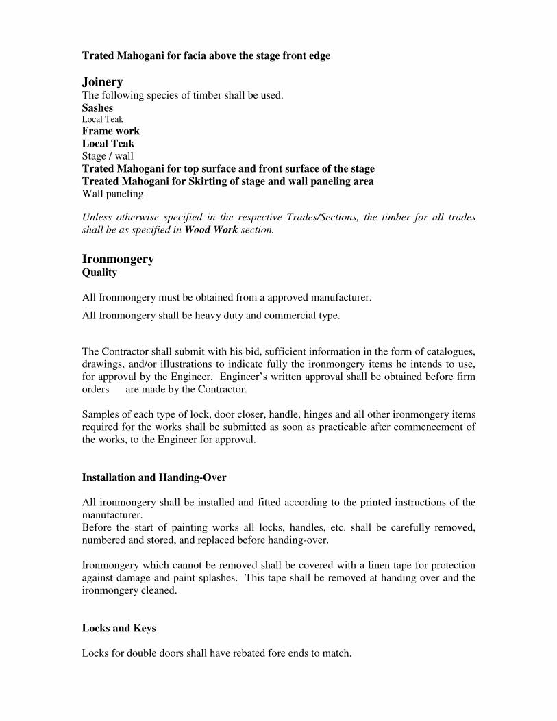
Trated Mahogani for facia above the stage front edge
Joinery The following species of timber shall be used.
Sashes Local Teak
Frame work
Local Teak
Stage / wall
Trated Mahogani for top surface and front surface of the stage
Treated Mahogani for Skirting of stage and wall paneling area
Wall paneling
Unless otherwise specified in the respective Trades/Sections, the timber for all trades
shall be as specified in Wood Work section.
Ironmongery Quality
All Ironmongery must be obtained from a approved manufacturer.
All Ironmongery shall be heavy duty and commercial type.
The Contractor shall submit with his bid, sufficient information in the form of catalogues,
drawings, and/or illustrations to indicate fully the ironmongery items he intends to use,
for approval by the Engineer. Engineer’s written approval shall be obtained before firm
orders are made by the Contractor.
Samples of each type of lock, door closer, handle, hinges and all other ironmongery items
required for the works shall be submitted as soon as practicable after commencement of
the works, to the Engineer for approval.
Installation and Handing-Over
All ironmongery shall be installed and fitted according to the printed instructions of the
manufacturer.
Before the start of painting works all locks, handles, etc. shall be carefully removed,
numbered and stored, and replaced before handing-over.
Ironmongery which cannot be removed shall be covered with a linen tape for protection
against damage and paint splashes. This tape shall be removed at handing over and the
ironmongery cleaned.
Locks and Keys
Locks for double doors shall have rebated fore ends to match.

Each lock shall be provided with 3 Nos. best quality brass keys wire together and each
clearly labeled with a laminated plastic or brass identification plate with the door number
or name engraved on it.
Schedule of Locks
The Contractor shall prepare and submit to the Employer a schedule of locks which shall
indicate position, type and designation of all locks, doors, etc. keys and key cabinets.
Hinges and Pivots
All hinges shall be best quality Brass fixed to sashes and frame with matching screws
supplied by the manufacturer of hinges.
Number of hinges per door shall be as shown in details. The following may be taken as a
guide. In case of discrepancies between the following guidelines and the information
furnished in drawings, instructions given by the Engineer shall prevail.
Doors lighter than 30 kg to have a minimum of 2 Nr. Butt Hinges 102 long, unless fitted
with a door closer, in which case 3 Nr. Butt Hinges shall be fitted.
Doors between 30 and 50 kg to have minimum of 3 Nr. Butt Hinges 102 long.
Doors heavier than 50 kg to have 4 Nr. Butt Hinges at least 102 long.
Top of upper hinges approx. 125 mm from top of door, underside of lowest hinge
approx.250 mm from bottom of door, central hinge(s) on fire doors to be equally spaced
between top and bottom hinges. On non-fire doors the third hinge is to be placed
immediately below the upper hinge, on non fire doors requiring 4 hinges, the fourth hinge
shall be placed centrally between the lower and the third hinge.
9.0 HIGH PRESSURE LAMINATED PARTITION SYSTEM
• Intermediate panel, pilaster & door – The intermediate panel is one continued
panel without any joints. All intermediate panels, pilasters and doors shall be
12mm thick with edges chamfered. The solid compact laminate (Phenolic Core
Board or equivalent) is based on thermosetting resins, homogeneously
reinforced with cellulosefibres. Top surface on both sides is melamine coated
which is scratch and impact resistant.
• Hardware and fixing – All pilasters are to be supported by adjustable foot and
non corrosive inserts. Top rail and wall fixing with an exterior polyamide
coating guarantees resistance to breakage, heat humidity and chemicals. The
base of the adjustable foot will be anchored to the floor with a clearance height
of 100-150mm. U Channel will be used for the fixing of intermediate panels to
the wall. Hinges :- Self closing
Accessories – Each toilet compartment shall be equipped with;

Heat & Bacteria resistant Polyamide Privacy Thumb turn.
Extruded Anodized for Epoxy Coated U-Channel
Heat & Bacteria Resistant Polyamide Door Knob.
Heat & Bacteria Resistant Polyamide Coat Hook.
Hinges with Heat & Bacteria Resistant Polyamide Cover.
Heat & Bacteria Resistant Polyamide Top Profile.
Heat & Bacteria Resistant Polyamide Adjustable leg.
Heat & Bacteria Resistant Polyamide Door stopper lining.
Colour of the accessories will be black
MINERAL FIBRE BOARD CEILING • The 15mm thick mineral fibre (square edge) ceiling tiles are to be suspended
using ”T” bars grid system at 600x600mmcentres. The main “T” bars are of
25mm width 38mm height. The cross bars of 25mm width and 32mm height.
The “T” bars system to be manufacture of hot dip galvanized steel. The edge
angle also to be hot dip galvanized steel of size of size 19x24mm.
• The suspension system to be hung from the roof structure along using
adjustable clips and 4mm diameter galvanized hanger rods at 1.2m intervals.
• The frame work should be installed level with no distortion of the suspension
system and to the entire satisfaction of consultant engineers.
• Ceiling system shall be capable of accommodating lighting diffuser panels,
loudspeakers and ventilation (A/C) outlets. Additional framing required for
such products shall be provided where required.
• Panels shall be easily removed for access to services.
• The ceiling panels shall be made out of humidity resistant and non
combustible mineral fiber and shall delivers acoustical performance that
achieves Noise Reduction Coefficient (NRC) of 0.55 and above.
• Ceiling panels shall be manufactured by a reputed company and manufacture
shall offer a minimum 10 years guarantee against visible sag for condition of
humidity up to 90% and 40o C.
FIRE DOORS
GENERALLY
All fire doors to be made to comply with BS 476 and come with a fire and insulation
rating of 120 minutes. The complete unit shall include the door jamb. The door to be
made of electro galvanized steel and coated to colour and finish specified by Consultant
Architect. The top coating to have baked paint or powder coated finishes. The door shall
be suitably insulated to enable non transfer of heat to opposite surface. All gasket
material to be heat resistant. No plastic fittings will be allowed in the construction.
View panels to comply with the BS standard or as detailed in the drawing elevation. The
view panel to use two layers of 6mm thick Georgian Polished Wired glass.
Fire doors to come with stainless steel hinges and panic bolt.
Fire resistance doors should have the capability of resisting the fire for hot less than 1
hour. The passage of flames and providing insulation as defined is under the prescribed
conditions of test appropriate to such construction in accordance with the current BS 476.
Fire door key
Key

FD60 A fire door with 60 units integrity and 60 minute insulation preparation
and complete with in tumescent seals.
SC Self closing device complying with BS 6459 doors closers.
FD60 (S) FD 60 (S) SC & VP - Fire door 60 minutes for rating, smoke sealing
self.
SC & closing and vision panel required
VP
PB-push bar Emergency opening device complying with BSEN 1125 1997
VP Vision panel – required resistance for 60 minutes
FR Fire resisting glazing (60) – 80 minutes resistance
Fire Door signs
All the doors must be signed with following which should meet 80mm x 80m ridged
plastic with 4 screws holes in size.
Sign, colour & Description
Pictogram
Fire door keep shut FDKS positioned at eye level on both faces of each leaf of
self closing fire doors.
Automatic fire door Used on doors connected to magnetic door hold open
devices
keep clear this releases the doors on activation of the fire alarm
system. Signs to be placed on the visible open leaf at eye
level when the door is held open, this is to avoid the
obstructing of the fire doors when released automatically.
Smoke seals in addition to the intumescent strips fire doors must be
fitted
With cold smoke seals or brushes. These smoke seals are
to be brush type and not rubber strip type.
Gaps & Hinges They should be close fitting to the frame with a maximum
gap of 6mm but 3m is the accepted working
gap and hung by 1 ½ pairs of all metal hinges with a
melting point of not less than 8000C (both nylon and nylon
bushed hinges are unacceptable)
Self closing Fitted with an effective self closing device capable of
closing the door tight against the stop, overcoming the
resistance of any latch or lock.

Glazing of fire doors Vision panel or any glazing on fire door, the glazing has
to be fire resisting of 60 minutes integrity (FRO 60)
meeting BS 476 part 22-1987-fire tests on building
materials and structures.
Glass type meeting FRG 60
‘Georgian wired” 6mm polished plate
Georgian wired (PPGW)
Glazing to FEG60 in design, embedded in intumescent paste rebates etc.
All fire doors must be certified by recognized testing laboratory (such as UL) ad must
have the laboratories certification label.
Fire doors can only be held open by a device that automatically release the fire alarm is
activated (such as an electromagnetic hold open device)
Glass thickness shall be 5mm
10.0 ROOF THERMAL INSULATION
Ultra double bubble double side polyethylene air bubble insulation material, both side
laminated with aluminium fire rated (R value 12.3 and thick 4-5mm) should be jointed
with double side tapes and laid over timber frame work.
11.0 SANITARY INSTALLATIONS
• Minimum 20 year guarantee for the product, 2 year warrantee for cistern
mechanism.
• There has to be a local agent with minimum 5 year work experience in selling the
product, information on locations where the fittings have been used to be
obtained.
• Water saving features to be available for the public toilets. Dwell flushing, water
capacity to be minimum (3-4.5 liters of water)
1. LOW LEVEL WATER CLOSET & CISTERN
High quality Vitreous China white colour fire clay ceramic Water Closet (high
quality) or equivalent to Engineer’s approval, complete with seat.
Close couple,dual flush,wash down/suction type, chrome plated top push button
approved colour Fire Clay Ceramic Cistern to Engineer’s approval, complete with
all necessary fittings and fixtures for flushings, securely fixed to wall.
2. SEMI PEDESTAL TYPE WASH BASIN
High quality Vitreous China white colour ,fire clay ceramic central taphole semi
pedestal

type Wash Basin , to Engineer’s approval complete with heavy duty commercial type
brass chromium plated pillar tap ,pop up waste with PVC bottle trap and all other
necessary accessories.
3. VANITY TYPE WASH BASIN
High quality Vitreous China white colour ,fire clay ceramic central tap hole
countertop
Wash Basin to Engineer’s approval complete with heavy duty commercial brass
chromium plated pillar tap, pop up waste with PVC bottle trap and all other necessary
accessories.
4. URINALS
High quality Vitreous China white colour ,fire clay exposed crome plated flush valve
urinals, to Engineer’s approval complete with PVC bottle trap and all other necessary
accessories.
5. SOAP HOLDERS, TOWEL RAIL, PAPER HOLDER
High quality stainless steel to engineer’s approval.
6. HAND SPRAY UNIT,SHOWER ROSES & TAPS
Hand spray units, shower roses ,taps shall be imported heavy quality PVC plated
make or equivalent to engineer,s approval.
7. MIRRORS
5mm thick imported clear float coated copper free mirrors with Bevel Pencil Edge
and distant plate.
12.0 ELECTRICAL INSTALLATIONS
1.0 General Requirements
1.1 Scope of Work
The scope of work shall include the provision of all materials, equipments, plant, labour
and services for the satisfactory installation, testing, commissioning and maintenance,
during the Defects Liability periods of the complete Electrical Installation works as
specified hereafter and as indicated on the Electrical Drawings, and shall include all
minor incidents and associated works which may not be specified in the in the contract
but, which are in the coursed of the functioning and operation of the completed Electrical
Installation, considered necessary in the sole opinion of the consultant/ supervisor, for the
safe and proper functioning and operation of the completed Electrical Installation.
1.2 Application of the Section
The items specified in this section are applicable to all sections of this specification.

1.3 Quality of Material and Equipment
The Contractor shall supply all equipment to be used under the scope of this contract with
a proven quality. The Contractor shall furnish manuals and operational instructions for
each facility where component items of mechanical and/or electrical are furnished under
this contract in accordance with the following clauses.
1.4 Manufacturer's Literature
The contractor shall submit to the Engineer three (03) copies of manufacturer's
descriptive literature in English for each and every item of equipment furnished complete
not later than 2 months prior to the date of provisional hand over.
1.5 Equipment Operation
The Contractor shall furnish manuals and operating instructions for each facility where
component items of mechanical and/or electrical equipment is furnished and/or installed
under this contract within the same time limits as described in Para 1.2 of this section and
in accordance with the following paragraphs.
The draft of each manual shall be submitted to the Engineer for approval before printing.
Each manual shall be printed on good quality paper and be bound in hard covers.
1.6 Operation and Maintenance Charts
The Contractor shall furnish three (03) copies of an operation and maintenance
instruction chart, which will incorporate applicable comprehensive descriptive
instructions, layouts, diagrams or any other information that will be necessary, and/or of
value to the operating and maintenance personnel.
1.7 Operation and Maintenance Manuals
The Contractor shall furnish three (03) copies of an operation and maintenance manual,
which shall contain complete instructions for overall operation, and maintenance of the
facility and its component parts. The manual shall also contain the operating and
maintenance instruction charts as specified in section 1.5.
1.8 Adequacy of information submitted
The Engineer/Consultant reserves the right to determine whether the above specified
information as furnished by the Contractor is adequate and complete and to require such
additional submission by the Contractor as necessary to ensure the satisfactory operation
of the various items of equipment and to fulfil the intent of the specifications.
1.9 Materials, fittings and accessories
Bidders are specifically cautioned to the following minimum considerations, which will
be reviewed by the Engineer/Consultant prior to approving any materials, item of
equipment or assembly of construction.
1. Full conformance with architectural and engineering design criteria, design
concepts and performance requirements.
2. Physical dimension requirements to satisfy the space limitations, indicated on the
drawings.
3. Static and dynamic weight limitations.

4. Audible noise level and vibration generation of equipment or assemblies with
moving parts.
5. Interchangeability of parts and components.
6. Accessibility for preventive maintenance, possible removal and replacement.
7. Compatibility for preventive maintenance, possible removal and replacement.
8. Compatibility with other materials, assemblies and components.
9. Full compliance with all applicable test requirements.
10. Full compliance with guarantee requirements.
Although these designs are mainly based on British Standards and IEE regulations,
equipment designed according to other internationally recognized standards and
satisfying the design criteria and performance requirements mentioned therein will be
acceptable if proved equal or better.
1.10 Un-named Products
Materials, equipment, fixtures, apparatus, appliances, accessories and similar
manufactured products supplied without a manufacturer's name or without a trade name
of the manufacturer, shall include catalogue numbers or similar descriptive data
indicating clearly that the products comply with all requirements of the specification and
the appropriate drawings.
Products which deviate in minor respects from those specified may be proposed after the
award of contract; providing that the proposal is accompanied by a document and
drawings of deviation clearly stating all deviations. Supplying and installing approved
deviations shall be executed at no additional cost.
1.11 Drawings
1.11.1 General
The Contractor shall carefully investigate the structural and finish conditions affecting all
work and shall arrange such work accordingly. He shall if necessary furnish additional
items, not shown on the drawings but necessary for the works to meet the specifications
and/or conditions, at no additional cost.
1.11.2 Verification of Dimensions
The Contractor shall check all drawings and the site conditions to familiarize himself
thoroughly with all details of the work and working conditions and verily all dimensions
in the field; and shall advise the Engineer/Consultant on any discrepancy or deviation. If
discrepancies or deviations are submitted to the Engineer/Consultant, the Contractor shall
wait for judgment and explanation in writing from the Engineer/Consultant before
performing any work.
1.12 Cutting and Repairing
The work shall be carefully laid-out in advance and no cutting of the structure will be
permitted. Damage to buildings and technical installations as a result of cutting for
installation shall be repaired by persons skilled in the trade involved at no additional cost
to the satisfaction of the Engineer/Consultant. If inspection or tests show defects, such
defective work or material shall be replaced or repaired as necessary and inspection and
tests shall be repeated at no extra cost. Repairs shall be made with new materials.

1.13 Safeguarding the Fixtures, Materials and Equipment during the Installation
Pipe and Ducts openings shall be closed with caps or plugs during installation for
protection against mechanical damage and the client shall not be responsible for theft
damage or loss of any of the materials. Fixtures and equipment shall be covered and
protected against dirt, water, moisture, sand and chemical or mechanical injury. Upon
completion of all works the fixtures, materials and equipment shall be thoroughly
cleaned, adjusted and tested to demonstrate its proper operation to the Engineer.
All materials and equipment shall be properly and adequately protected by the contractor
before, during, and after installation. Material or Equipment damaged due to inadequate
attention of the Contractor shall not be accepted and the client reserves the right to
request replacements for such equipment at the handing over. Replacement of items
damaged due to unavoidable circumstances during removal shall be paid on measure and
pay basis.
It is the responsibility of the Contractor to clean the installation at close of work every
day and also to hand over a clean and neat installation at completion.
1.14 As-Built Drawings
The Contractor shall maintain a complete set of drawings at the site on which details shall
be marked exact locations of all mechanical, electrical and control systems complete with
dimensions taken from column center lines. The crossings of other services, the
termination and equipment layout shall be marked during the installation and the
Contractor shall obtain the approval of such drawing before preparing the final as-built
drawings. As built drawings shall be turned over to the Engineer in accordance with
requirements as specified with the handing over
1.15 Samples
Samples of all electrical, materials, fittings and accessories should be handed over to the
Engineer/Consultant and approval obtained before commencing the work. The work shall
be carried out using such fittings and accessories. These samples will be returned to the
Contractor on successful completion of the project.
1.16 Access Openings
The contractor shall provide all access, openings required for inspection and maintenance
of the installations.
1.17 Language
All information, communications and correspondence shall be in the English Language.
1.18 Codes and Standards
All equipment, materials and workmanship shall be in conformity with relevant and
applicable British Standards and codes of practice where available and currently valid.
1.19 Inspection and Testing
The Contractor shall perform all tests as directed by the Engineer/Consultant and shall
demonstrate the proper operation of all systems. All labour materials and equipment
required for tests shall be provided by the Contractor at no extra cost. Defective
equipment, materials and workmanship shall be replaced, repaired or corrected by the
Contractor and re-tested and re-demonstrated for proper operation.
An Inspection and Testing certificate of the electrical installation conforming to the 17th
edition of the IEE regulations (BS: 7671) should be obtained form a Charted Engineer
before handing over of the installation for relevant authority for approval. If any defects
were detected at this stage Contractor shall rectify the defect or replace the defected items
and re-test if necessary.

2.0 L.V. Main Switch Boards and Sub Distribution Boards
2.1 Scope of work
Scope covers the fabrication, supply, erection and commission of the Main Switchboard
and Sub Distribution Boards inclusive of mounting cable connections, site tests and
commissioning.
Design of the switchboard with detailed drawings and the requirements of trenches inside
the power room and where necessary shall be provided by the successful Bidder.
LV Main Switch Boards and Sub Switch Boards specified in this section shall apply to
all sections of these specifications.
Applicable Publications
Refer Section: General Requirements.
2.2 Applicable Standards
BS EN 60439 – 1, 1994 Low voltage switchgear and control assemblies.
IEC 446, 1989 Identification of conductors by colours and numerals
IEC 529, 1989 Degree of protection (IP Code)
IEC 664-1, 1992 Insulation co-ordination of low voltage switchgear and
control – gear
IEE Regulations 17th
Edition Wiring regulations.
2.3 Operating Parameters and Conditions
Rated continuous voltage: 230 V, 50 Hz, phase to earth and 400V,
50 Hz, phase to phase.
Number of phase: 3 phase, 4 wire system
Type of Earthing: TT system (IEE Regulations)
Installation type: Indoor/Outdoor
Degree of protection of cubicles: (IEC 529) IP 44, Natural ventilation or forced
ventilation.
Maximum Ambient Temperature: 40°C. (Salty condition)
Insulation level: between live parts and earth LI -6 kV PF, 50 Hz- 2.5 kV
Between phases LI –7.5 kV PF, 50 Hz- 4 kV
Fault level at the transformer LT terminals: 18 kA
Pollution category: 1 (IEC 439-1)
2.4 General
Main Switch Board and Sub Distribution Boards in each floor shall be of the wall
mounting, metal clad, flush fronted cubicle type with front access. The cable entries shall
be from the bottom of the switchboard. The switchboards shall be constructed in
accordance with B.S. 5486 for operation in a 400 Volts 3 phase, 4-wire 50 Hz system.
Generally, the switchboards shall be capable, as a whole of withstanding without damage
the electrical, mechanical and thermal stresses produced under short circuit conditions.
Special attention shall be given to insulation and finish of all items and no hygroscopic
material shall be used in any position, and all components shall have a good finish and
perform at 40 C and 90% R.H. (Salty condition).
2.5 Construction

Each cubicle framework shall be fabricated from rolled steel angle sections and shall be
self-supporting when assembled and of standard size, uniform in height and depth. The
cubicle panels and doors shall be fabricated from minimum 14SWG sheet steel to provide
a clean, flush and rigid construction without welded cross struts. The cubicle shall be
strengthened by horizontal and vertical folded channels and corner gussets.
Full access shall be provided to control equipment inside cubicles by means of suitable
hinged doors secured with an approved locking device. All doors shall be provided with
approved type of gasket. The cubicles framework shall be manufactured from electro-
zinc plated sheet steel, and finished with electro-statically applied epoxy powder paint
with a thickness lot less than 80 microns. The epoxy powder paint shall be grey in colour
unless otherwise specified by the Engineer/Consultant.
2.6 Bus Bars
The main bus bars shall be arranged horizontally in a ventilated separate compartment.
The bus bars shall be of adequate cross sectional area to given the current ratings as
shown in the drawings, after allowing for all necessary derating factors. The main bus
bars shall comprise four rectangular section bars of equal cross sectional areas (i.e. full
size neutral) fabricated from hard-drawn high conductivity (HDHC) copper, electro-
tinned for the entire length, rigidly mounted on proprietary made non hygroscopic
insulators. All connectors from the bus bars to the circuit breakers, shall be identified by
means of colour PVC sleeving or painting to indicate the phases.
Bus Bar insulators shall be selected for BIL of 6kV, impulse withstand voltage of 1.2/50
µs impulse, and power frequency withstand for 1minute of 2.5kV at 80kPa and in dry
condition.
2.7 Switch Board Arrangement
The contractor shall provide the proposed switchboard layout drawings for the
Engineer’s/Consultant’s approval before fabrication of switchboards. Switch Boards
shall be arranged to suit the space available.
2.8 Earthing
A suitable earthing terminal shall be provided on the frame of each section of the
switchboard for connection to earth. An electro tinned HDHC copper earth bar shall be
provided in each switchboard for earthing of all outgoing circuits and equipment frames.
2.9 Moulded Case Circuit Breakers (MCCB)
MCCB shall comply with IEC 947-2 or other approved equivalent standards. Frame sizes
current ratings shall be as shown in the drawings. The short circuit breaking capacity of
the MCCB shall be not less than the minimum prospective fault level at the point where
the MCCB is installed.
Calibration temperature shall be at 40 0C the “on” “OFF” and “TRIP” positions of the
operating handle shall be clearly defined.
The breaker shall be of moulded material with good mechanical strength, heat-resistant
properties to withstand the forces under fault current, appropriate to its interrupting
capacity rating. The over current device shall trip all the three phases simultaneously
when operating under over-current and short circuit condition.

2.10 Earth Fault Relays
Earth fault relays to be of the core balance type with adjustable sensitivity and shall be
fully tropicalized. All over-current and earth fault relays shall be tested and calibrated to
the satisfaction of the engineer and all costs connected with this shall be deemed to have
been included in the tender price.
2.11 Current Transformers
All current transformers used for metering and protection shall comply with B.S. 3938:
1973 and they shall be properly selected for which it is used. They shall have adequate
VA rating to match the burdens of the connected load without exceeding its accuracy
limits. At least 50% higher VA rating shall be preferable to accommodate the future
updating of relays and the protection scheme and automation.
Current transformers connected to protection relays shall be class 5P10 while that
connected to measuring instruments shall be class 1M5. Current transformers shall be
provided with adequate support to prevent movement during short circuit condition and
shall be so installed to permit easy access for replacement.
2.12 Indicating Instruments (Meters)
Indicating instruments shall be flush mounted in the switchboard front door unless
otherwise specified. All meter front dimensions shall be 96 x 96 mm and be provided
with a square or rectangular scale extending over an angle of not less than 900. Digital
Instruments of approved type may be used.
The meters shall be fully tropicalized and capable of withstanding the full fault current
passing through the primary of their corresponding current transformer. Mechanical zero
adjustment shall be provided and accessible from the front without dismantling.
The requirements for the various types of meters are as follows:
a. Ammeter
Ammeters shall be current transformer operated type and of accuracy Class 1.5. All
ammeters shall have a continuous overload capability of 120% of its rated value and be
provided with a 20% over scale.
b. Voltmeter
Voltmeters shall be of accuracy Class 1.5 with 500 volts scale. All voltmeters shall be
provided with selector switch of the rotary type with break before make contacts for
selection to measure the phase to phase and phase to neutral voltages. The voltage
selection RY, YB, BR, RN, YN, BN, shall be clearly marked on the switch.
c. Power Factor Meter (if applicable)
Shall be three-phase four wire, unbalanced load type with accuracy Class 1.5 The scale
reading shall range from – 0.5 to 0.5
2.13 Labels
All cubicle doors shall be appropriately labelled to indicate the service. Labels shall also
be provided to identify all items of equipment, circuits, cables and where applicable
current ratings of circuit breakers and setting of relays. Details of the labels shall be
submitted to the Engineer/Consultant for approval prior to manufacture.

3.0 Final distribution board 3.1 Scope of Work
Scope covers the supply, installation and commissioning of the Final Distribution Boards
and AC Distribution boards as per the BOQ. The location of the distribution board is
indicated in the drawing.
Distribution boards specified in this section shall apply to all sections of these
specifications.
• Applicable Publications Refer to section: General Requirements
Applicable Standards
All MCCB, disconnecting devices shall conform to IEC 947-2, IEC 947-3.
The contact separation shall confirm to table 14 of IEC 439-1
All MCB shall confirm to IEC 898.
All RCCB shall confirm to BSEN 61008.
3.2 Construction
It shall be of a reputed make conforming to BS 5486 or equivalent flush mounted suitable
for 400/230 Volts 3 phase/single phase 50Hz supply. The breakers shall be “DIN” rail
mounted type complete with bus bars, neutral and earth bars.
Distribution boards shall be completely enclose in dust, insect and vermin proof units
housing MCB’s, MCCB's contactors, and all necessary items of equipment whether
specified herein or not.
It shall be suitable for indoor service in ambient temperature of up to 400C with 90%
relative humidity at maximum continuous rating without exceeding the maximum
temperature permitted by the relevant B.S. specifications (This site is very near to the
Sea).
All distribution boards shall be manufactured to withstand as a whole the electrical,
mechanical and thermal stress that could be produced by the prospective fault levels at
their respective points of application.
Special Attention shall be given to insulation and finishes of all items and no hygroscopic
materials shall be used in any position and all components shall have a clean finish.
Each distribution board shall be so arranged that all connections are easily accessible
from the front of board. Adequate space shall be provided for out going circuit wiring so
that the cable will not be required to pass between the back of the enclosure and the
circuit breakers.
All cables shall be bundled by means of nylon self-locking cable ties and fixed in a neat
and systematic manner.
Each distribution board shall be provided with a label of laminated plastic black,
engraved in white with the words D.B. followed by the reference designation.
3.3 Residual Current Circuit Breakers (RCCB)
Residual current circuit breakers shall be the current operated type 2 or 4 pole as shown
on the drawings, suitable for operation on 230/400 volts, 50Hz A.C. system and
manufactured to comply with the relevant British standards, BSEN 61008.
The residual current circuit breakers shall be the high sensitivity type with tripping
currents as shown, and shall be so designed that the tripping action is completely
independent of the supply voltage. The rupturing capacity of the earth leakage circuit
breakers shall be adequate to withstand the prospective fault level at the respective points
of application.
4.0 LV Cables 4.1 Scope of Work

Supply, laying, termination, and commissioning of the cables shall be as per the BOQ.
All cables shall be laid, clipped to the walls or slabs, or laid in buried conduit or enclosed
in conduits clipped on to the wall or slab as described in the BOQ.
LV Cabling specified in this section shall apply to all section of these specifications.
4.2 Applicable Publications
Refer to Section: General Requirement
4.3 Applicable Standards
BS 951: 1986 Specification for clamps for earthing and bonding purposes
BS 6346: 1989 Specification for PVC insulated cables for electricity supply.
All multi core cable up to sub distribution boards shall be as indicated in the BOQ and
the drawings. The single core/two core cables running in conduit shall be PVC insulated
with or without PVC sheath. All cables shall be with high conductivity stranded copper
conductors and sizes shall be as indicated in the contract drawings.
4.4 Cable Codes
The following cable codes are used throughout and as called for by this specification and
drawing.
a. PVC Polyvinyl chloride insulated
b. PVC/PVC Polyvinyl chloride insulated and Polyvinyl Chloride sheathed.
c. PVC/SWA/PVC Polyvinyl chloride insulated steel wire armoured and
polyvinyl chloride sheathed.
d. XLPE/PVC Cross linked polyethylene insulated and polyvinyl chloride
sheathed.
PVC, PVC/PVC, PVC/SWA/PVC CABLES
PVC, PVC/PVC, PVC/SWA/PVC Cables shall be of 600/1000 volts grade with high
conductivity stranded copper conductors of sizes as shown in the drawings.
The cables shall be manufactured to B.S. 6004 or B.S. 6376 as appropriate. Insulation
colours can be in accordance with current editions of British IEE wiring regulations.
XLPE/PVC CABLES
Cross linked polyethylene insulated cables shall be of 600/1000 volts grade
comprising high conductivity stranded copper conductors manufactured to B.S. 5467
and finished with extruded black PVC over sheath.
4.5 Underground Cable Installation
Underground cables shall be laid in trenches or pulled into cable ducts where indicated in
the drawings. Full safety precautions shall be taken to prevent damage to the cable during
the installation.
All trenches shall be excavated to provide a minimum cover of 750mm in open ground
and under pavement and 1000mm under all roadways. Details of the trench construction
shall be as specified in other clauses of this specification.
Where cable passes through a roadway, pavement or enters a building, it shall be
threaded through steel or PVC pipes of minimum 100mm dia. Pipes under roadways shall
be protected with 100mm thick concrete on both sides and top.
All pipes shall be properly sealed to prevent ingress of water. The cable trench shall have
water drain outlets to prevent collecting water inside the trench.
For work where it is involved in digging or interference with existing roads, car parks,
pavements and other services such as gas, water etc., prior approval shall be first obtained
from relevant authorities before carrying out such work.
Cables shall normally go under all obstructions such as mains, sewers, drains conduits
and the like.

The removal, alteration or diversion of mains, sewers, drains, conduits and the like, shall
normally be avoided.
The contractor shall excavate trial holes as and when required by the Engineer/Consultant
in order to determine the location of existing cables or other utility services and mains.
The contractor is advised to familiarize himself as to the nature of the surfacing materials
of both paved and unpaved surfaces roadways etc., and shall satisfy himself before
submitting his tender as to he nature of the subsoil and in general shall obtain all
necessary information as to the risks contingencies and other circumstances which may
influence or affect his tender price as no claim for additional cost will be allowed.
4.6 Termination
The contractor is to be wholly responsible for the sealing and termination of all cables
erected under this contract (in salty condition).
The contractor shall terminate all cable ends and shall make final connection to all sub
switchboards.
The specified sub main cable cross-sections may have been oversized to minimize
voltage drop over long runs. Where these cables are too large for termination within the
distribution board terminal blocks, isolating switches, etc., suitable reducing terminating
tags or lugs shall be used.
Cable sealing and termination is to be in accordance with the best current practice and of
first class workmanship. Where cable sheaths are used, as earth continuity conductor
glands are to have the necessary contact surfaces or straps to provide a low resistance
path under fault conditions.
Compression type glands shall be used for the termination of underground cables. The
design of compression glands to be such that the cable is not twisted when the gland is
tightened.
Appropriate bending radius depending on the cross sectional area of the cable shall be
provided so that the cable insulation is not subjected to stress or damages due to bending
of the cable.
4.7 Straight Joints
Straight joints in any of the cables installed under this contract will only be permitted in
very exceptional circumstances and only with the Engineer’s/Consultant’s approval in
writing. The cost of such straight joints, if permitted by the Engineer/Consultant shall be
born by the contractor.
All joints, which are buried in the ground, shall be compound filled. The design of the
box and the composition shall provide an effective seal to prevent moisture-gaining
access to the conductor ferrules and Armour clamps.
A suitable contract joint marker to the Engineer’s/Consultant’s approval shall be placed
above each under ground cable joint to mark its position. The depth of burial of the cable
joint shall be indicated on the joint marker.
4.8 Excavation of trenches, backfilling and reinstatement
Excavation of trenches where required, shall include all timbering, pumping and baling
required and the provision of all necessary labour, plant, tools, additional soil, fuel and
motive power for such purposes and the cost of this service and of the supply of the
expendable materials shall be included in the contract price.
The contractor shall include for all materials and labour to reinstate the ground to the
same condition as existed prior to excavation.
All trenches shall be of sufficient width to enable the following minimum spacing
between cables to be maintained.
Between HVC and LV cables: 300 mm

Between LV cables: 75 mm
Between LV and ELV cables: 300 mm
Before the cables are laid, the bottom of the trench shall be lined with sifted soil, which is
to be punched down to a thickness of 50mm to form a bed. After the cables are laid, the
first 75mm depth of cover back fill shall consist of sifted soil over which shall be placed
protective cable slabs of an approved design.
After all cables and protective cable slabs have been laid, the trenches shall be backfilled
in 150mm layers, each layer being well rammed and consolidated.
The surfaces of the re-filled trenches shall be temporarily reinstated and maintained in a
thoroughly safe condition until complete consolidation of the soil is achieved.
The contractor shall supply backfill material necessary for the replacement of unsuitable
excavation material together with the backfilling reinstatement and removal of surplus
material, which shall be included in the contract price.
4.9 Cable Slabs
Protective cable slabs shall be of reinforced concrete and unless otherwise approved,
shall be 750mm long, 230mm wide and 50mm thick. Samples of the cable slab shall be
submitted to the engineer or the engineer for approval before production and installation.
The supply and laying of cable protective slabs shall be included in the rate for cable
laying.
4.10 Cable Ladders
Cable ladders shall be of the sizes shown on the drawing. All ladder systems shall be
built up from components from a matching range of straights, bends, tees, reducers,
supports etc.,
The ladder system shall be capable of supporting a load of 75-kg/linear meter over a span
of 6.1 meter with a vertical deflection (sag) of less than 50 mm at mid span.
The ladder system shall be of an approved proprietary manufacture of welded or site
fabricated construction using either aluminium or steel components or both. All steel
components shall be hot dip galvanized. Electro galvanizing will not be accepted.
Unless shown otherwise on the drawings, ladder runs shall be parallel to walls, ceilings
floors, etc., Supports shall be installed at center-line distances not greater than that shown
on the drawings or, where not directed at distances not greater than those recommended
by the manufacturer for the loading concerned.
The Contractor shall co-operate with other trades so as to ensure that the completed
ladder installation does not interfere with other services in the same area.
4.11 Cable Tray
Cable trays shall be of sizes shown on the drawings. All tray systems shall he built up
from a matching range of straights, bends, reducers, tees, supports etc., They shall be of
an approved proprietary manufacture fabricated from minimum 1.2 mm mild steel
perforated to between 25% and 50% of the total area. After fabrication the trays shall be
hot dip galvanized.
Trays shall have upturned edges and be of a width as indicated in the drawing, suitable
for the number of cable to be supported and shall be supplied with purpose-made
galvanized steel bracket suitable for mounting from the building stricture.
Support brackets for cable trays shall be fabricated and finished as for the tray and
provided at intervals not exceeding 1200 mm with 2 bolts to each bracket. Bracket shall
he fixed with not lees than 2 bolts to the wall/slab or other available and approved
supports.
Cable shall be supported by a cable tray inside the cable trench. The contractor shall
submit the detailed drawing of the cable trays for the approval of the Engineer/Consultant

4.12 Test During Laying
Where required by this specification and as required from time to time by the engineer,
the contractor shall subject completed portions of the cable installation to voltage tests to
prove the soundness of the conductor insulation and the soundness of the protective
sheathing.
4.13 Cable Record Drawings
Cable record drawings of “As Installed” drawings showing the exact route of cables and
positions of all joints etc. shall be submitted for the Engineer’s/Consultant’s review.

5.0 Conduit Installation 5.1 Scope of Work
All the non-armoured cables and cable bunches shall be installed in PVC conduits.
Contractor shall submit the drawings of the conduits where it unavoidable to break the
structure to place the conduits. The conduit runs shall be installed in the way that
minimum damage and necessity of re plastering etc. is applicable.
Conduit installation specified in this section shall apply to all sections of these
specifications.
5.2 Applicable Publications
Refer Section: General Requirements
5.3 Applicable Standards
BS 6053: 1991 Specification for outside diameter of conduits for electrical
installations and threads for conduits and fittings
BS 6099: Conduits for electrical installations
5.4 General
All conduits, fittings and accessories shall be PVC and shall comply with British
standards. Conduits shall be concealed in walls, columns and floors unless otherwise
shown or called for in this specification and drawings.
5.5 Installation
All concealed conduits shall be arranged with an adequate number of boxes accessible for
the life of the installation so as to allow easy draw in or draw out of any cables at any
time. Conduits size shall not in any circumstances be less than 20mm dia and cables
drawn in shall not be greater than appropriate number permitted in IEE wiring regulation
16th
edition. Cables for low voltage circuits shall not be drawn into the same conduit for
extra low voltage systems. A number of final sub circuits may be grouped together in
large conduits provided that all sub circuits in one conduit are of the same phase. In the
case of three phase circuits all 3 phases and neutral of any circuit should be drawn into
the same conduit. Wiring lighting shall be run exclusively in separate conduits.
Where a large group of cables run, those may be put in a metal conduit trunking, in which
a false ceiling or a false wall covering shall be used to cover such trunking or surface
conduits. All surface wiring for the final circuits shall be in PVC casings of white colour
Where condensation is likely to occur in surface conduits they shall be laid with falls so
as to drain off condensed moisture without entry into termination.
Immediately on completion of installation of conduits during building construction, all
exposed conduits and boxes shall be plugged effectively against the ingress of water and
dirt particularly where concrete will be poured.
Such seals shall be maintained in good order for such time as is necessary to complete
wiring and connection of fittings and switches.
On completion of erection, the Engineer/Consultant will inspect the conduits before any
wire is drawn in. All conduits shall be swabbed out and free from moisture to the
Engineer’s/Consultant’s satisfaction, before wiring is commenced.
5.6 Conduit Fittings
At every lighting outlet points the conduit shall terminate into a PVC junction box either
one way or multiway as required. These boxes shall be suitable for flush mounting. At
every switch position, conduits shall terminate in a 86mm x 86mm or 186mm x 148mm
injection moulded PVC box. At every socket outlet, telephone, TV or bell position,
conduits shall terminate similar to switch position shall be attached to the boxes using the
clip-in adaptors and suitably glued.

Conduits shall be installed with junction boxes, end boxes, draw wires etc., such that the
cables can be drawn in after the installation has been completed without damage to cables
and their installation.
6.0 General Lightning and Power Installation 6.1 Scope of Work
Scope covers the Supply, install, wire and commission of all light fittings, wall switches,
socket outlets and isolators as per the BOQ. The locations of each point are given in the
drawing. However exact locations shall be verified from the Engineer.
General lightning and power installation specified in this section shall apply to all
sections of these specifications.
6.2 Applicable Publications
Refer to section: General Requirements
6.3 Applicable Standards
Each light fitting for interior use shall be design, manufacture and tested in accordance
with the appropriate section of BS 4533:102.1/EN 605982.1 and together with all
components shall be suitable for service and operation in the local climatic conditions.
Louvers shall comply with CIBSE LG3 VDT recommendations. The luminaries shall be
class 1 electrical.
All other accessories shall conform to following specifications.
Fluorescent tubes BS1853
Chokes BS2818
Capacitors BS4017
Starters BS3772
Lamp Holder and Starter Holder BS5042
All lighting fittings shall be earthed.
6.4 General
The contractor shall supply, install, wire and connect all lighting fittings as shown on the
drawings. The exact location of all lighting fittings must be checked on the architectural
detailed drawings before installation is commenced. The contractor will be expected to
examine the architectural floor plans and ceiling details in order to fully familiarize with
the type of ceilings and surfaces into and upon which lighting fittings are to be installed.
The contractor shall supply all fixing, brackets angles etc., necessary to fix the lighting
fittings in the locations shown.
The numbers of lighting fittings for the different areas of the building have been
calculated using the photometric data equivalent to Phillips, Thorn, Thorlux or Fitzgerald
Lighting Fittings and GE, Osram and Phillips lamps. If the contractor is offering
fitting/lamps different to the above, he shall provide the calculations to prove the required
numbers of lighting fitting using the photometric data of the lamp offered to the
satisfaction of the Engineer/Consultant.
Care must be taken to ensure that other services such as air conditioning, water piping
etc., are properly coordinated and the contractor will be required to maintain close liaison
with other contractors in this respect.
6.5 Lighting Fittings
6.5.1 General
The types of lighting fittings to be provided are shown on the drawings and described in
the accompanied schedule of lighting fittings.
All lighting fittings shall be supply complete with lamp, control gears and power factor
correction capacitor.

At every light fitting, an approved type-earthing terminal shall be provided for
connection to the earth continuity conductor of the final sub-circuit.
Plastic diffusers where used, shall be of non-deteriorating and ultra-violet stabilized
material and shall not change in shape with time or due to handling. Plastic diffusers shall
be washed with a detergent solution and drip-dried immediately prior to installation to
restrict electrostatic dust adhesion.
Fittings and accessories for external use shall be of weatherproof construction specially
treated for corrosion for use in salt laden atmosphere. Totally enclosed fittings shall have
sealing gaskets and shall be insect-proof.
Cables within the lighting fittings shall be neatly bundled by nylon self-locking cable ties.
Wiring shall be properly routed and secured away from heat-generating accessories
like control gear etc.
Each light fitting for interior use shall be design, manufacture and tested in accordance
with the appropriate section of BS 4533:102.1/EN 605982.1 and together with all
components shall be suitable for service and operation in the local climatic conditions. It
is the Contractor’s responsibility to get the approval from the Engineer/Consultant for all
light fittings before the installation.
6.5.2 Recessed Florescent Fitting 6.5.2.1 Light fitting
The lighting fitting shall be recessed modular fluorescent luminaries for use in standard
concealed metal tray ceilings, having low brightness reflectors categorized to CIBSE
LG3 Category 2 or 3 as per VDT recommendations.
Module Size: 1200*300 mm
Number of lamp per fitting: 2 x 36 Watts
The luminaries shall be double parabolic reflector louver type fitting. 6.5.2.2 Lamps
The fluorescent lamp shall be manufactured and tested in accordance with the BS 1853,
IEC 81 and shall be bi-pin types with following details.
Power Output: 36W T8 linear fluorescent tubes
Diameter: 26mm
Length: 1200mm
Initial Lumen output: 2450
Light Colour: Neutral white
Colour Rendering Index: 80-90 6.5.2.3 Control Gear
The control gear shall be switch start and shall incorporate high power factor and
interference suppression capacitors and shall be quick or resonant start type. Choke shall
be impregnated and solidly filled with polyester resin or their approved high melting
compound and shall be manufactured to restrict the third harmonic content to less than
25% of the uncorrected current value and shall be silent in operation. 6.5.2.4 Materials/ Finish
Body shall be white stove enamelled steel. The louvers shall be specular and semi-
specular aluminium with low iridescent finish. The louver shall be opened by one
end when replacing the lamp.
All fittings shall confirm to BS 4533 and shall be have approved design and of a reputed
make and shall be made with M.S. Sheet not less than 24 SWG and painted with one coat
of anti-corrosive paint and finished with white stove enamelled. Capacitors shall be
parallel connected. All accessories shall conform to the following specifications. 6.5.2.5 Installation/ Mounting
The installation shall be parallel to the ceiling grid. The luminaries shall be self
supported and shall complete with wire suspension and adjusting facilities to ensure

correct levelling within the ceiling aperture. The suspension wire shall GI and shall
be galvanized.
The light fitting shall be connected via suitable length of supply wire so that it can
be moved either sides of the ceiling aperture depending on the floor partitioning.
Installation locations are as per the drawing. 6.5.2.6 Surface mounted/Suspended Fluorescent Lamp Fitting
The lighting fitting shall be surface mounted/suspended type fluorescent luminaries to be
used as specified in the drawing.
Module Size: 1200 mm
Number of lamp per fitting: 1x36 Watts
The lamp shall be completed with clear acrylic prismatic diffuser with switch start
control gear.
6.5.3 Down Lights 6.5.3.1 Down Lights - Recessed
Recessed down light of 13/18W Compact Fluorescent Lamps (CFL) switch start shall be
installed in areas specified as per the drawing. CFL shall have the Total Harmonic
Distortion (T.H.D) less than 20%. The reflector shall be aluminium with anodised finish.
Body shall be galvanized steel or polycarbonate. The light colour shall be neutral white. 6.5.3.2 Down Light - Surface Mounted (on slab-indoor)
The down light shall be circular/rectangular polycarbonate interior surface
mounted luminaire with opal diffuser and white body with high power factor
control gear. The lamp shall be 13W compact fluorescent with neutral white light
colour. The installation location shall be as per the drawing. 6.5.3.3 Down Light - Surface Mounted (on slab-outdoor)
The down light shall be circular/rectangular polycarbonate corrosion resistant, totally
enclosed exterior surface mounted luminaire with opal diffuser and white body with high
power factor control gear. The lamp shall be 13W compact fluorescent with warm white
light colour. These shall be installed in the balcony area as per the drawing.
6.5.4 Wall light – Outdoor
The outdoor type wall light shall be wall bracket mounting type. The wall light body
shall be cast aluminium painted white and silver grey and opal glass lamp enclosure.
The lamp canopy shall be conical type with opal methacrylate or grey painted ABS.
The diameter of the canopy shall be 475mm while the height of the lamp with the
canopy excluding the bracket shall be 445mm. The lamp shall be 13W 4-pin cap
type compact fluorescent with warm white light colour. 6.5.4.1 Lamp Terminal Box
Each perimeter lamps shall be fed from the lamp terminal box as per the drawing.
The box shall flush mounted and suitable for outdoors installation confirm to IP65.
The box shall be completed with copper terminal bar of suitable cross section, fuse
etc. 6.5.4.2 Wall Light Fitting (Bracket type)
The lighting fixture shall be sphere type suitable for indoor application. The sphere
shall be opal polycarbonate and the bracket shall be engineering polyester. The
diameter of the sphere shall be 250-300mm. The lamp shall be 13W CFL with
neutral white light colour.
6.6 18 Inch Ceiling Mounted fans with Guard
The ceiling fans shall be 18 inch three bladed type. Blades shall be covered with anti
corrosive removable steel guard. The ceiling fans shall be complete with inductive type
regulator conforming to BS 5060. The motor shall be single-phase 230V, 50Hz totally
enclosed capacitor type with grease packed ball bearing. The terminal block on the fan as
well as the capacitor and the fan hook shall be provided with removable covers.
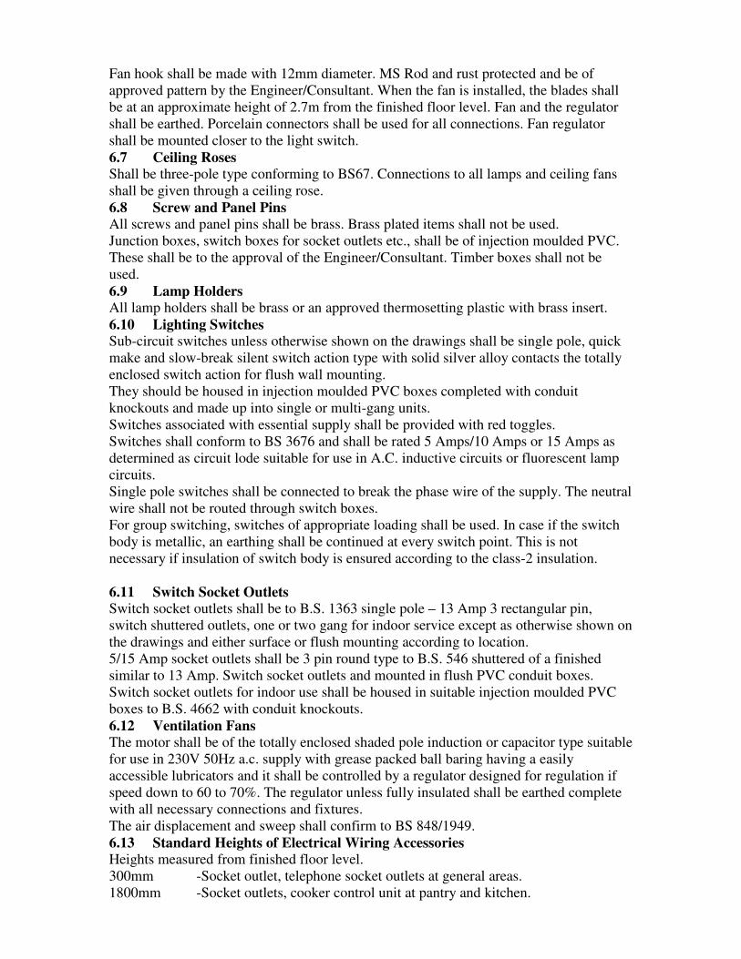
Fan hook shall be made with 12mm diameter. MS Rod and rust protected and be of
approved pattern by the Engineer/Consultant. When the fan is installed, the blades shall
be at an approximate height of 2.7m from the finished floor level. Fan and the regulator
shall be earthed. Porcelain connectors shall be used for all connections. Fan regulator
shall be mounted closer to the light switch.
6.7 Ceiling Roses
Shall be three-pole type conforming to BS67. Connections to all lamps and ceiling fans
shall be given through a ceiling rose.
6.8 Screw and Panel Pins
All screws and panel pins shall be brass. Brass plated items shall not be used.
Junction boxes, switch boxes for socket outlets etc., shall be of injection moulded PVC.
These shall be to the approval of the Engineer/Consultant. Timber boxes shall not be
used.
6.9 Lamp Holders
All lamp holders shall be brass or an approved thermosetting plastic with brass insert.
6.10 Lighting Switches
Sub-circuit switches unless otherwise shown on the drawings shall be single pole, quick
make and slow-break silent switch action type with solid silver alloy contacts the totally
enclosed switch action for flush wall mounting.
They should be housed in injection moulded PVC boxes completed with conduit
knockouts and made up into single or multi-gang units.
Switches associated with essential supply shall be provided with red toggles.
Switches shall conform to BS 3676 and shall be rated 5 Amps/10 Amps or 15 Amps as
determined as circuit lode suitable for use in A.C. inductive circuits or fluorescent lamp
circuits.
Single pole switches shall be connected to break the phase wire of the supply. The neutral
wire shall not be routed through switch boxes.
For group switching, switches of appropriate loading shall be used. In case if the switch
body is metallic, an earthing shall be continued at every switch point. This is not
necessary if insulation of switch body is ensured according to the class-2 insulation.
6.11 Switch Socket Outlets
Switch socket outlets shall be to B.S. 1363 single pole – 13 Amp 3 rectangular pin,
switch shuttered outlets, one or two gang for indoor service except as otherwise shown on
the drawings and either surface or flush mounting according to location.
5/15 Amp socket outlets shall be 3 pin round type to B.S. 546 shuttered of a finished
similar to 13 Amp. Switch socket outlets and mounted in flush PVC conduit boxes.
Switch socket outlets for indoor use shall be housed in suitable injection moulded PVC
boxes to B.S. 4662 with conduit knockouts.
6.12 Ventilation Fans
The motor shall be of the totally enclosed shaded pole induction or capacitor type suitable
for use in 230V 50Hz a.c. supply with grease packed ball baring having a easily
accessible lubricators and it shall be controlled by a regulator designed for regulation if
speed down to 60 to 70%. The regulator unless fully insulated shall be earthed complete
with all necessary connections and fixtures.
The air displacement and sweep shall confirm to BS 848/1949.
6.13 Standard Heights of Electrical Wiring Accessories
Heights measured from finished floor level.
300mm -Socket outlet, telephone socket outlets at general areas.
1800mm -Socket outlets, cooker control unit at pantry and kitchen.

1400mm -Switches, dimmer switches, fan regulators and general areas.
1800mm -Main switches, earth leakage circuit breakers.
1800mm -MCB Distribution boards
2400mm -Wall brackets, lamp fittings, fuse distribution board geyser outlets, and
power outlets.
2400mm -Pendant lamp fittings
Note: -
The above heights shall be varied according to the interior design, and installation heights
shall be adjusted accordingly to the Engineer’s/Consultant’s approval.
7.0 Earthing System 7.1 Scope of Work
Earthing systems, testing L.V. equipment specified in this section shall apply to all
sections of these specifications.
7.2 Applicable Publications
Refer to Section: General Requirements
7.3 General
Earthing system and lighting protection for each building shall include ground rods,
cable-accessories, devices and other items necessary for the complete and satisfactory
installation and operation of all equipment.
7.4 Earthing System
a. Equipment Earthing
All exposed metalwork of all electrically operated equipment, metal cable trays and other
exposed (un-insulated) metal work of all electrical services shall be earthed by cables and
conductors of adequate sizes as given in the regulations. All cables above 6mm2 in size
shall be connected by nuts and bolts as relevant with pressure cable connections of
appropriate size.
b. Conductors
All earthing and earth continuity conductors shall be installed in strict conformity with
the I.E.E. regulations and British standard codes of practice.
Cables and conductors shall be sized in accordance with BS table D2M, with the
exception that the smallest size of conductor is 2.5mm2.
This cable or conductor shall be identified by green/yellow insulation. All earthing bars
shall be identified by green/yellow colour codes.
Earth conductors shall be provided for the following equipment.
c. Socket Outlets
From each socket outlet-earthing terminal a wire shall be provided. The wire shall be
connected to the earthing terminal in the outlet box, or junction box.
d. Switches
From each switch earthing terminal a wire shall be provided. The wire shall be connected
to the earthing terminal in the outlet box, or junction box.
e. Luminaries
From each luminaire (lighting fixture) earthing terminal wire shall be provided. The wire
shall be connected to the earthing terminal in the outlet box.
f. Distribution Boards
From the earthing bar in the distribution boards earthing wires shall be provided to the
equipment as cable trays, outlet boxes etc., as specified.
7.5 Distribution System
Provide separate green-yellow insulated equipment earthing for each single or three-
phase circuit. The required earthing conductor shall be installed in the common conduit

or cable with the related phase and/or neutral conductors. Single-phase sub circuits
required for 230 volts lighting, socket outlets and motors shall consist of phase, neutral
and earth conductors.
7.6 Panel Boards
In addition to the active circuits, provide pressure connectors for all three-phase spare
circuits.
7.7 Earth Electrodes
Earth electrodes shall be of earth pipe, earth rod connected to the ground grid of buried
conductors to the area covering not less than 1m2 at the building close to the sub-stations.
The incoming cable from the main distribution board shall be connected to the earth
electrode. The earth electrode and the conductors shall be sized to the full short circuit
current value of the sub-station or incoming supply cables as relevant.
The grounding grid shall be of soft annealed high conductivity copper strip of area not
less than 100sq.mm and will be installed at a depth of 2m or more in the ground. The
distance between copper strips shall not less than 100mm.
The earth electrode resistance shall be less than 5 ohms tested on a dry day.
7.8 Conductors
All cables and conductors shall be of copper. Joints in copper tape shall be braced. No
joints are allowed in sub-circuit cables.
7.9 Residual Current Protection
Socket outlets shall have earth leakage protection provided with residual current circuit
breakers (RCCB) 30/100 mA sensitivity of the current operated type. The breakers shall
be suitable for operation on a 400/230V level at a frequency of 50Hz.
7.10 Earth Loop Impedance and Earth Resistance Tests
The entire installation shall be tested for Ohmic resistance as given in regulation E.3 and
Appendix 6 of the IEE regulations. The installation shall be tested to the requirements of
regulation E.4 of the regulations. The test results shall be submitted to the
Engineer/Consultant for approval. The engineer or his representative shall be present at
the testing.
7.11 Earthing L.V. Equipment
All equipment shall be earthed by connection (via green/yellow covered earth wire) to a
common LV inter connected earthing terminal in the Power Room in accordance with the
following: -
The earth resistance of the complete earthing system including all connections between
equipment and earth shall not exceed 5 ohm.
All parts of the earthing system, which may carry low voltage currents shall be so
designed and constructed that damage does not result from the passage of such currents.
The minimum size of the LV earthing conductor shall be as follows: -
In circuits with live conductors not larger than 16mm2 the minimum size of the earthing
conductor shall be not smaller than the live conductor.
In circuits with live conductors exceeding 16mm2 and less than 35mm2, the minimum
size of the earth conductor shall be not smaller than 16mm2.
In circuits with live conductor-exceeding 35mm2 and above, the minimum size of the
earth conductor shall be not smaller than half the size of the live conductor.
All earth conductors shall be covered by a green/yellow PVC sheath. Green-Yellow shall
not be used for any active, neutral, switch or control wiring and shall be used solely for
earth connection.

13.0 LIGHTNING PROTECTION The Contractor shall be responsible and shall include in his costs for the supply, erection,
testing, commissioning and setting to work of a lightning protection system as indicated
on the tender drawings.
The base of the down conductors shall be taken to earth electrodes. Each electrode shall
be 600X600mm copper-bond type fitted with clamps for earth tape connection. The earth
electrode shall be protected at the top by concrete brick lines complete with the
inspection cover. Provision shall be made within the pit for disconnection of the tape for
test purposes.
The Contractor shall test the resistance to earth of the complete system in accordance
with BS Code of Practice 326 and BS 6651 and obtain a resistance to earth not exceeding
1 ohm. The contractor shall submit a detailed working drawing with all the components
properly marked for a complete workable system (as recommended by the Manufacturer).
The lightning protection system shall comprise of the following but not limited to:
a) Air terminals of 25 x 3 mm bare copper conductor at the top of the structure. 25 x
3 mm copper strips shall be fixed at the top of the structure as shown in the
drawings using proper clamps and connectors of approved type and make.
b) Down conductors of 25 x 3 mm bare copper or 70 sq. mm LSF insulated copper
wire from the air terminals to the earth electrodes.
c) Earth terminations of 600X600mm copper plate earth electrode buried 1.6m
below the ground.
The lightning conductor (air terminal) shall be connected to the down conductor with a
connecting clamp. All joints of the lightning conductors shall be carried out using
purpose made clamps of approved types and makes. No joints will be permitted in the
down conductors.
1.1.1 Installation of Lightning Protection System Lightning protection systems shall be installed in accordance with the Particular
Specification and Drawings, and as directed by the Engineer.
1.1.2 Scope This Sub-section covers lightning protection systems applicable to buildings and similar
structures. It does not cover the protection of overhead lines and other specialized
applications. The installation shall conform to the requirements and recommendations set
out in the British Standard BS 6651 “Code of Practice for Protection of Structures against
Lightning”.
1.1.3 Type of Lightning Protection System A lightning protection system shall comprise air termination connected by down
conductors to earthing electrodes. In larger schemes more than one of any or all of the
above items may be used. Air terminations may be interconnected by means of roof
horizontal conductors.
1.1.4 Air Termination Air termination shall consist of vertical or horizontal conductor(s) or combination of
both.
No part of the roof shall be more than 5m from the nearest horizontal conductor. For
larger flat roofs, this shall be achieved typically by an air termination network mesh of
approximately 10mX10m.
On a reinforced concrete structure, the air termination shall be connected to the
designated reinforcing bars in the number of positions required for down conductors.

All metallic projections on or above the main surface of the roof which are connected,
intentionally or fortuitously, to the general mass of the earth should be bonded to, and
form part of, the air termination network.
1.1.5 Down Conductor The dimensions of down conductors to be used shall be annealed tinned copper strip 25 x
3mm.
Where the steel work of the structure is used as down conductor, coordination with the
Building Contractor is required to ensure the continuity of the steel work. In this
connection the ends of the steel work shall be connected to the lightning protection
system by a jointing method which is suitable for bonding dissimilar metals and approved
by the Engineer. A test joint shall be provided at each connection.
When down conductors adhered on the external wall are specified, they shall be fixed by
means of suitable spacer saddles at regular intervals of not exceeding 1m apart. The down
conductor shall follow the most direct path possible between the air termination network
and the earth termination network. When more than one down conductors are installed,
they shall be arranged as evenly as practicable around the outside walls of the structure
starting from the corners.
Each down conductor shall be connected to an earth termination.
1.1.6 Test Joint Test joints shall be of phosphor bronze, gunmetal or copper. They shall comprise a heavy
circular base, to which a heavy circular cover of the same material shall be bolted. The
flat copper conductor shall be overlapped and placed so that they are clamped between
the cover and the base by means of at least four screws or studs.
The test joints shall be positioned so that they shall not be tampered with by unauthorized
persons. In cases where this is not possible, the earth tape/rod connector clamp shall be
used as an alternative test point in place of the test joint.
1.1.7 Earth Termination Unless otherwise specified, earth termination shall be of rod electrodes complying with
Sub-section 6.3.
Each earth termination shall have a resistance to earth not exceeding the product given by
10Ωtimes the number of earth terminations to be provided. The whole of the lightning
protection system shall have a combined resistance to earth not exceeding 10Ω. Where,
due to local conditions, it is difficult to obtain a value of less than 10Ωby the sole use of
rod electrodes, alternative or additional methods, e.g. the use of deep bore holes, the
installation of tape or plate electrodes complying with Section 6, may be used at the
discretion of the Engineer.
1.1.8 Spacer Saddle Spacer saddles shall be of high quality metal. For copper conductors, brass or gunmetal
shall be used. Non-metallic spacer saddles shall only be used when down conductors are
provided with PVC sheathing.
1.1.9 Connection to Earth Termination Down conductors and bonding conductors shall be connected to the earth electrode in
accordance with Sub-section 6.4. Each connection shall be separately clamped and shall
be fitted with a warning notice in accordance with Sub-section 3.3 in Part A
1.1.10 Bonding to Other Services Lightning protection systems shall normally be kept segregated from the metalwork of
other services. Minimum isolation clearances as given in BS 6651 shall be maintained.
However, in certain circumstances, e.g. where fortuitous contact with other systems
cannot be avoided, earth electrodes for lightning protection may, at the discretion of the
Engineer, be bonded to other such services including the metal sheath and armouring of

low voltage cables, the consumer's low voltage earth system, metal water pipes and steel
reinforcement for the foundation and structure.
Cables and earthing systems belonging to the Supply Authorities, the Telephone
Company and other authorities shall not be bonded except with the written permission of
such Authorities. Gas pipes shall not normally be connected to any earth electrode.
1.1.11 Bond Bonds for use in connecting the lightning protection system of other metal work shall be
of soft annealed copper strip of 25 x 3mm. Bonds connecting movable items to the
lightning protection system shall be of flexible copper strand 475/0.5mm diameter or
equivalent. Connections to other metalwork shall be of negligible resistance, metal to
metal and mechanically sound with non-ferrous nuts, bolts and washers using clamps
where necessary.
1.1.12 Joint in Conductors Joints in roof conductors and/or down conductors shall be made by double riveting or by
suitable tape clamps. When clamps are used, the tape clamps shall each be provided with
at least 4 screws or bolts. All such joints shall be tinned and shall have negligible
resistance and good mechanical strength.
Alternatively, connectors may be jointed together by means of exothermic or thermal
welding utilizing the high temperature reaction of powdered copper oxide provided that
the proper material and equipment are used in accordance with the manufacturer's
recommended process.
1.1.13 Testing On completion of the installation, the lightning protection system shall be tested for
continuity between air terminations and earthing terminations and the resistance shall be
recorded. The earthing resistance of each earthing electrode shall also be tested and
recorded.
The tests shall be carried out in accordance with Part C of this Specification and shall be
submitted to the Engineer for approval. All instruments used for testing shall be properly
calibrated.
14.0 LOOP PILE CARPET
All loop pile carpets to be imported Philadelphia or equivalent and should satisfy the
following.
Tufted yarn weight - 20 ounce
Dye method - Solution Dyed
Construction - Tufted level loop pile
Fibre - 100% perma colour polypropylene
Tufted pile height - 0.187 inches
Finished pile thickness - 0.118 inches
Stitches per inch - 11.3
Gauge - .1.10
Primary backing - Polypropylene

Secondary backing - Polypropylene
Width - 12’0” x 15’0”
Density - 6120 ounces cubic yard
NBS. smoke density
chamber flaming - Less than 450
Electrostatic Propensity - Permanent static control
Wear warranty - Ten year limited commercial wear warranty
Edge of the carpet layer should be fixed and finished with edge strips/ edging.
Under Layer for cut pile & loop pile carpets
The under layer should be luxurious high density latex foam ‘Guardian R’ or equivalent
with flame retardant properties, satisfying flammability test (BS+4790). It should have
ribbed profile with minimized carpet rucking.
Under layer weight - 1180g/m2
Thickness - 8mm BS 4051
Breaking strength &
Extension under force BS 2576
Work of compression BS 4098
BS 4052
Loss in thickness after dynamic loading BS 4052
Loss in thickness after static loading BS 4939
Resistance to cracking BS 5808
15.0 AUDITORIUM ACOUSTIC AND VIDEO
Auditorium Acoustics
Minimum noise is expected considering the location and the construction of the
auditorium.
Perimeter walls of the auditorium shall preferably be constructed of hollow cement
blocks. However,15mm thick marine treated plywood panels rigidly fixed on 50mm x
45mm hard wood battens is proposed on the specific portions of the inner surface of the
auditorium, as indicated in the drawing.
Coarse woven fabric lining on 5mm thick sponge rubber layer is also proposed on the
plywood sheet paneling, panel sizing and layout scheme as per the architect’s or interior
designer’s ID scheme. Other areas of the inner walls shall be plastered with coarse
granular “popcorn” / fine mountainous of Nippontex kote or equivalent cement layer or
applied with acoustic paint (on normal plaster).
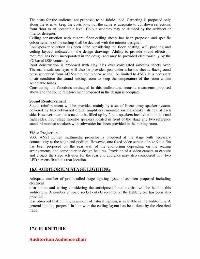
The seats for the audience are proposed to be fabric lined. Carpeting is proposed only
along the isles to keep the costs low, but the same is adequate to cut down reflections
from floor to an acceptable level. Colour schemes may be decided by the architect or
interior designer.
Ceiling construction with mineral fiber ceiling sheets has been proposed and specific
colour scheme of the ceiling shall be decided with the interior designer.
Loudspeaker selection has been done considering the floor, seating, wall paneling and
ceiling layouts indicated in the design drawings. Ability to provide sound effects, if
required, has been incorporated in the design and may be provided electronically by the
PC based DSP controller.
Roof construction is proposed with clay tiles over corrugated asbestos sheets over.
Thermal insulation layer will also be provided just under asbestos sheets. Background
noise generated from AC System and otherwise shall be limited to 45dB. It is necessary
to air condition the sound mixing room to keep the temperature of the room within
acceptable limits.
Considering the functions envisaged in this auditorium, acoustic treatments proposed
above and the sound reinforcement proposed in the design is adequate.
Sound Reinforcement
Sound reinforcement will be provided mainly by a set of linear array speaker system,
powered by two networked digital amplifiers (mounted on the speaker string), at each
side. However, rear areas need to be filled up by 2 nos. speakers located at both left and
right sides. Four stage monitor speakers located in front of the stage and two reference
standard monitor speakers with subwoofer has been provided in the mixing room.
Video Projection
7000 ANSI Lumen multimedia projector is proposed at the stage with necessary
connectivity at the stage and podium. However, one fixed video screen of size 9m x 5m
has been proposed on the rear wall of the auditorium depending on the seating
arrangements, and some interior design features. Provision of a video camera to capture
and project the stage activities for the rear end audience may also considered with two
LED screens fixed at a rear location.
16.0 AUDITORIUM STAGE LIGHTING
Adequate number of pre-installed stage lighting system has been proposed including
electrical
distribution and wiring considering the anticipated functions that will be held in this
auditorium. A number of spare socket outlets re-wired at the lighting bar has been also
provided.
It is observed that minimum amount of natural lighting is available in the auditorium. A
general lighting proposal in line with the ceiling layout has been done by the electrical
trade.
17.0 FURNITURE
Auditorium Audience chair

An ergonomically manufactured high back chair with heavy duty scotch guard
protected fabric and powder coated steel base to be mounted to the floor with
two legs. Manufacturer certificate for scotch guard protection of fabric shall be
submitted together with bid submission. Powder coating thickness should be
suitable for the marine environment and Corridors not acceptable. Chair size to
be 570 mm in width, 1000mm – 1030mm in overall height and 665mm in depth.
Chair seat back cover to be heavy duty nylon material and chair seat to provided
numbering facility. Writing tablet which could be folded in to the arm rest to be
provided. Top cover of arm rest should be in timber. Chairs should be fixed on
curved tiers as per given layout.
Sample of chair and sample card of fabric should be submitted for inspection,
selection and approval. All technical literature complying to specifications to be
submitted together with the bid submission. 03 years comprehensive warranties
should be given. If necessary testing could be done to identify the compliances.
All necessary expenses for the testing should be borne by the contractor.
Head table and podium
Solid Timber Furniture
Supply of wooden furniture with Treated Mahogany wood. All timber should
have free from defects, free from knots and free from irregular grains. Joints of
timber panels with defective bonding, uneven surfaces, and overlaps, gaps in face
area not accepted. Termite treatment and necessary treatments should be done.
Certificates for treatments taken from the reputed independent organizations
should be submitted for approval of client and the consultant before
manufacturing. All furniture to be finished with Mahogany stain or any other
specified and applied with two coats of heavy duty lacquer (Refer detail for
dimensions)
Solid Timber Internal Framework Of Furniture
Furniture structure of the table top and base (side panels) to be reinforced with
treated Mahogany timber framework and applied with wood preservative and
finish to smooth surface. Termite treatment should be done for durability.
Certificates for treatments taken from the reputed independent organizations
should be submitted for approval of client and the consultant before
manufacturing. Tenderers shall responsible for membrane sizes, strength and
durability.
Submission of samples, technical literature and test certificates All bidders shall submit samples together with relevant technical literature
complying to give specification for all items required in manufacturing of all
categories of furniture for inspection.
Samples of all categories of furniture to be forwarded for approval of client and
the consultant before manufacturing.

Randomly selected finished samples of furniture to be inspected in labs for
compliances. All necessary expenses for the required tests to be borne by the
successful bidder.
Submission of warranties 03 year comprehensive warranties for each items and equipments should be given.
18.0 STAGE CURTAIN
1. MAIN CURTAIN (Location A)
• Triple Pleated Two –Way type Curtain is Stitched with Two sections and
including with Ribbon Border for the bottom part of the curtain.
• Time for Opening to be open within 35 seconds.
• Color of front curtain – Samples catalog to be submitted for colour selection.
• Material – Velvet
• Lining – Black colour lining stitched with Twill
• Curtain to be operate with Electrical and Manual Operating Systems
including Puller System with Stand, Side Puller System and heavy duty
Cables (6mm Galvanized) Racers and Electric Gear Motor (0.25 H/P)
• Ability to operate the curtain in Control Room to be provided.
• Curtain Track to be fabricated in Heavy duty Iron work and treatment should
be according to the Eng. Details.
• Curtain to be moved on Heavy Duty Nylon Rollers (Runners) with 6mm
Galvanized cable (Cable management system)
• Curtain track to be directly fixed to the GI or MS truss work which is fixed to
the roof structure. Size and the design of the truss to be finalized considering
the site conditions. Treatment should be according to the Eng. Details.
• Size of the curtain to be finalized according to the site measurements.
2. FRILL CURTAIN FOR MAIN CURTAIN (Location A1)
• Triple Pleated Frill Curtain to be stitched with Ribbon Border for the bottom
part (End) of the curtain
• Color of the front curtain – Samples catalog to be submitted for colour
selection.
• Material - Velvet
• Lining – Black colour lining stitched with Twill
• Frill curtain to be directly fixed to the Iron Truss Work; in front of the Main
Curtain
• Size of the curtain to be finalized according to the site measurements.
3. MAIN SIDE WING CURTAINS BOTH SIDE OF THE MAIN CURTAIN-
(LOCATION B)
• Curtain to be stitched with Ribbon Border for the bottom part of the curtain.
• Colour – Black color – Samples catalog to be submitted for colour selection.

• Material – Velvet
• Lining – Black colour with lining stitched with Twill
• Curtain Track to be directly fixed to the GI or MS Truss work which is fixed
to the roof structure. Size and the design of the truss to be decided
considering the site conditions No corrosion allowed . Treatment should be
according to the Engineer’s. Details.
• Size of the curtain to be finalized according to the site measurements.
4. REAR CURTAIN (BLACK CURTAIN) – (LOCATION C)
• Triple Pleated Two –Way type Curtain is Stitched with Two sections and
including with Ribbon Border for the bottom part of the curtain.
• Time for Opening to be open within 35 seconds.
• Color of front curtain – Samples catalog to be submitted for colour selection.
• Material – Velvet
• Lining – Black colour lining stitched with Twill
• Curtain to be operate with Electrical and Manual Operating Systems
including Puller System with Stand, Side Puller System and heavy duty
Cables (6mm Galvanized) Racers and Electric Gear Motor (0.25 H/P)
• Ability to operate the curtain in Control Room to be provided.
• Curtain Track to be fabricated in Heavy duty Iron work and Treatment should
be according to the Engineer’s. Details.
• Curtain to be moved on Heavy Duty Nylon Rollers (Runners) with 6mm
Galvanized cable (Cable management system)
• Curtain track to be directly fixed to the GI or MS truss work which is fixed to
the roof structure. Size and the design of the truss to be decided considering
the site conditions. Treatment should be according to the Engineer’s. Details.
• Size of the curtain to be finalized according to the site measurements.
5. FRILL CURTAIN FOR REAR CURTAIN (BLACK CURTAIN) -
(LOCATION C1)
• Triple Pleated Frill Curtain to be stitched with Ribbon Border for the bottom
part (End) of the curtain
• Color of the rear curtain – Samples catalog to be submitted for colour
selection.
• Material - Velvet
• Lining – Black colour lining stitched with Twill
• Frill curtain to be directly fixed to the Iron supportive structure work; in
front of the Main Curtain
• Size of the curtain to be finalized according to the site measurements.
6. SIDE WING CURTAINS (SIDE LEG CURTAINS) – (LOCATION D)
• Curtain to be stitched with Ribbon Border for the bottom part of the curtain.
• Colour – Black color – Samples catalog to be submitted for colour selection.
• Material – Velvet
• Lining – Black colour with lining stitched with Twill
• Curtain Track to be directly fixed to the GI or MS Truss work which is fixed
to the roof structure. Size and the design of the truss to be decided

considering the site conditions. Treatment should be according to the
Engineer’s. Details.
• Size of the curtain to be finalized according to the site measurements.
7. FRILL CURTAIN AT CENTRE OF STAGE (AT LOCATION OF SIDE
LEGS (E)
• Triple Pleated Frill Curtain to be stitched with Ribbon Border for the bottom
part (End of the curtain)
• Color for the frill curtain – Samples catalog to be submitted for colour
selection.
• Material - Velvet
• Lining – Black colour lining stitched with Twill
• Frill curtain to be directly fixed to the Iron supportive structure at ceiling
level.
• Size of the curtain to be finalized according to the site conditions
• Curtain to be hanged to 1st Dia. Heavy duty Galvanized Pipe (G.I.) and
directly fix to the roof structure.
8. IRON TRUSS WORK
• Curtain Tracks to be directly fixed to the Hot dip galvanized truss work
which is fixed to the roof structure. Size and the design of the truss to be
decided considering the site conditions. Curtain supporting structure
Treatment should be proposed by the contractors / suppler.
• Size and structural system to be decided by the supplier considering the
available spaces (Ceiling void), existing sizes and spacing of existing roof
truss arrangement.
• Exposed surfaces or formworks shall be painted on same colour of adjoining
ceiling.
WARRANTIES
• 03 year comprehensive warranties should be given for operation system,
Cable management system, motors, fixing and the colour of fabric.
SUBMISSION OF SAMPLES, SHOP DRAWING AND TECHNICAL
LITERATURE
• Samples, sample catalogs, shop drawing including fixing details and technical
literature should be submitted by the tenderes or bidders together with duly
filled tender documents.
• Maintenance manual/ maintenance procedure to be submitted to the client.
19.0 FABRIC WALL PANELLING
• Coarse woven fabric lining finished with 5mm thick rubber sponge layer
(back layer) fixed on 15 mm thick treated marine plywood sheet, should be
fixed on 50mmx 45mm treated hard wood (Thulan or Balau) frame work.
Timber framework should be fixed rightly with 1200mmx1200mmm grid
pattern to the wall by nails on leveled surface to maintain the neatness of the

finished surface. Treated mahogany beading (with neatly finished edges)
should be fixed along all joints to cover nail heads which were used to fix
fabric finished panels to the framework. Top edge and the bottom edge should
be finished with treated mahogany molding and skirting.
20.0 FIRE PROTECTION AND DETECTION SYSTEM
1.0 GENERAL
1.1 SCOPE OF WORK
This section specifies the requirements for the design, manufacture, transport,
delivery to site, unloading, complete erection/installation, site testing, setting to
work and maintenance for a period of one year of the Fire Protection, Detection
and Alarm system for the protection of goods, personnel, buildings etc. of
proposed Rabindranath Tagore Memorial Auditorium at the University of
Ruhuna.
The work covered in this section shall include, but not to be limited to all labour,
materials, equipment and services required in connection with Fire Protection
System and related work as stipulated in the specifications, drawings and the
equipment list for proposed building for Rabindranath Tagore Memorial
Auditorium at the University of Ruhuna.
To meet the requirements of the Local Fire Service Authority regulations the
following services shall be provided in the premises complying with BS standard
and Fire Offices Committee (FOC) regulations and as detailed in the drawings.
1. Supply and Installation of hose reel system to cover the entire building as
per drawings and specifications.
2. Supply and Installation of portable Fire Extinguishers at the locations
shown on drawings.
3. Supply and Installation of Conventional Fire Alarm Control Panel, Smoke
detectors, Manual Call Points, Alarm Sounders with wiring as per
drawings and specifications.
Contractor should obtain all approvals and compliance from the Fire
Regulation Authorities/Fire Services Department of Sri Lanka before
commencement of installation, during and after completion of the
installation as specified by Fire Service Department of the Urban Council.
1.2 Submissions
The Contractor shall submit for approval the following documents and samples
in quantities as indicated:
1.2.1 Shop Drawings
Shop drawings of all protection systems, electrical circuit and wiring diagram

and any other drawings necessary for fabrication and installation of the system.
1.2.2 Technical Literature of Equipment
Technical literature of all equipment proposed to be used in the system
inclusive of dimensional drawings, capacity tables, test reports and other
relevant information shall be supplied in triplicate for the Engineer to determine
the adequacy and suitability of the equipment for the proposed fire Life Safety
system.
1.2.3 Maintenance & Operating Manuals
Maintenance and operating manuals of all equipment supplied shall be
furnished in triplicate with detailed wiring of the equipment and instructions of
the regular maintenance of the equipment. All manuals should be printed, and
ring bound with hard cover.
A schedule which may be in the form of a material list giving all particulars
together with ordering references of all replaceable parts for all the equipment
which will be supplied.
1.2.4 Samples
Samples of all materials to be supplied under the contract such as
Extinguishers, Smoke Detectors and other electric components shall be supplied
to the Engineer for approval. Such samples shall be kept with the Engineer
until completion of the Works and same will be released to the Contractor on
completion of work. The items of supplies used for the project shall be at least
equal in quality to the approved sample.
1.2.5 As-Built Drawings
On completion of the installation, the Contractor shall prepare a set of As-built
drawings incorporating all changes made to the original design and drawings,
which drawings shall represent an accurate description of the installed systems.
These drawings shall be bound with covers in to an album and handed over to
the Engineer.
1.2.6 HANDING OVER DOCUMENTS
The final handing over documents to be submitted by the Contractor on
completion of the installation shall comprise the following :
a) Operation and maintenance manuals (3 copies)
b) Commissioning sheets (3 copies)
c) Test reports (3 copies)
d) As built drawings (3 copies)
These documents in required number of copies specified should be supplied to
the Engineer within 30 days on issue of taking over certificate.
1.2.7 TRAINING OF OWNER'S STAFF

Bidders shall submit with the bid, a full proposal of the recommended training
necessary for the owner's personnel to attend to routine testing, maintenance
service and minor repairs including an indication of the duration of such
training.
The number of persons required to be trained shall be determined jointly by the
Engineer, and the Contractor.
The scope of training shall include on-site training and such training shall be
prior to hand-over of the system. Technical training and system operation
instructions to the owner's personnel shall also be provided during the
commissioning and performance tests phases of the system.
System operation instructions shall be given by an experienced and competent
representative of the Contractor who is thoroughly conversant with the fire
protection system installed.
1.2.8 TESTING AND COMMISSIONING
Bidders shall submit with the bids, a complete proposal with time schedule for
testing and commissioning of the fire protection system. The program shall
include a trial operation of all main equipment with any necessary adjustments
to ensure that the system is working correctly. The Contractor shall provide all
instruments and equipment together with commissioning engineers and
adequate assistance for carrying out the commissioning and testing activity
which shall be done in accordance with the recommendations of relevant
Standards. If any portion of the works fails to pass the tests, the Contractor
shall, at his own expense carry out such alterations or replacements as are
required to the satisfaction of the Engineer. The Engineer shall be at liberty to
call for further commissioning when such alterations have been completed to
their satisfactory. The Contractor shall provide commissioning spares at his
own expense.
Spare parts earmarked for maintenance shall not be used during this period.
1.2.9 MAINTENANCE CONTRACT
Bidder shall submit the terms and charges for service and maintenance contract
along with the bid.
1.3 STANDARDS
The installation shall comply with the following standards and references :
BSEN-3 - Portable Fire Extinguishers
BS 5274 - Fire hose reels (water) for fixed installation.
BS 5839 (BSEN 54)-Specification for smoke/ heat detectors & alarm
system
ICTAD - Fire Detection & Protection system

NFPA - Fire Detection & Protection system
2.0 FIRE PROTECTION SYSTEM
2.1 GENERAL
Fire protection system shall comprise of the following fire pumps.
Item Type Qty
Main Pump Centrifugal 01
Stand-by Pump Centrifugal 01
The capacities of fire pumps are given in the detailed technical specifications.
The fire pumps will be installed at the Fire pump room at the Ground level of
the building. The underground water sump is located as shown in the drawing.
Manual swing type fire hose reels complying with BS 5274 shall be installed at
each floor level in the locations shown in the drawings. The hose reels shall be
3/4"(19mm) connected to the wet riser system by flanges of heavy duty
galvanized steel pipe to BS 1387.
Hose reel riser pipe work shall be heavy duty galvanized iron (GI) pipes to BS
1387 with Victualic grooved couplings or similar approved mechanical
couplings.
The distribution pipe network shall be kept pressurized at all times.
The pipes shall be run concealed in ceiling voids where available and in the
ducts provided. The hose-reels and landing valves shall be housed in Fire
cabinets located as indicated in the drawings.
The work shall conform to BS 5306: Part 1 except where otherwise required by
this Specification.
2.2 DESIGN REQUIREMENTS
- Water flow rate at Main pipe -
2.27 l/s
- Water quantity at furtherst hose reel connection -
0.5 l/s
- Minimum pressure required at hose reel nozzle (4.5mm) -
4.0 bar
- Maximum static pressure in hose reels when water is shut off -app.
5.5 bar
2.3 OTHER REQUIREMENTS
2.3.1 If the specification, capacities and sizes given are not adequate or have to be
changed to suit an equipment of any manufacturer for producing required design
conditions the Contractor shall include his charges for these with the quotation.
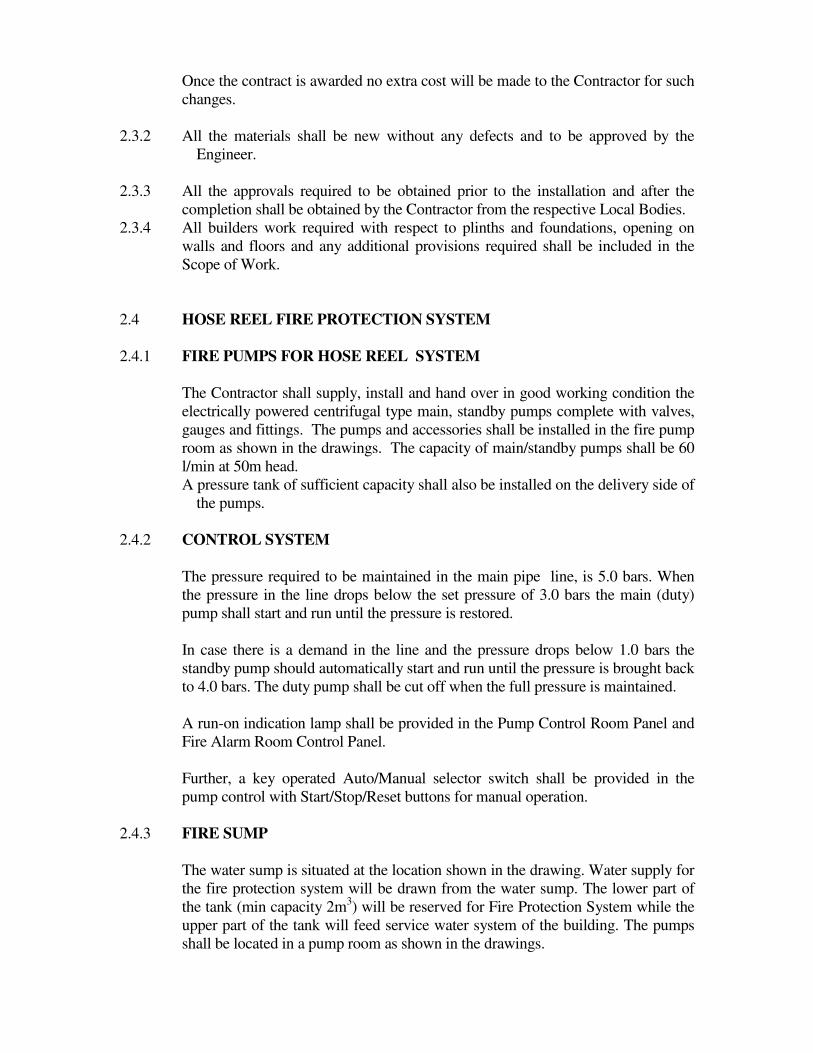
Once the contract is awarded no extra cost will be made to the Contractor for such
changes.
2.3.2 All the materials shall be new without any defects and to be approved by the
Engineer.
2.3.3 All the approvals required to be obtained prior to the installation and after the
completion shall be obtained by the Contractor from the respective Local Bodies.
2.3.4 All builders work required with respect to plinths and foundations, opening on
walls and floors and any additional provisions required shall be included in the
Scope of Work.
2.4 HOSE REEL FIRE PROTECTION SYSTEM
2.4.1 FIRE PUMPS FOR HOSE REEL SYSTEM
The Contractor shall supply, install and hand over in good working condition the
electrically powered centrifugal type main, standby pumps complete with valves,
gauges and fittings. The pumps and accessories shall be installed in the fire pump
room as shown in the drawings. The capacity of main/standby pumps shall be 60
l/min at 50m head.
A pressure tank of sufficient capacity shall also be installed on the delivery side of
the pumps.
2.4.2 CONTROL SYSTEM
The pressure required to be maintained in the main pipe line, is 5.0 bars. When
the pressure in the line drops below the set pressure of 3.0 bars the main (duty)
pump shall start and run until the pressure is restored.
In case there is a demand in the line and the pressure drops below 1.0 bars the
standby pump should automatically start and run until the pressure is brought back
to 4.0 bars. The duty pump shall be cut off when the full pressure is maintained.
A run-on indication lamp shall be provided in the Pump Control Room Panel and
Fire Alarm Room Control Panel.
Further, a key operated Auto/Manual selector switch shall be provided in the
pump control with Start/Stop/Reset buttons for manual operation.
2.4.3 FIRE SUMP
The water sump is situated at the location shown in the drawing. Water supply for
the fire protection system will be drawn from the water sump. The lower part of
the tank (min capacity 2m3) will be reserved for Fire Protection System while the
upper part of the tank will feed service water system of the building. The pumps
shall be located in a pump room as shown in the drawings.

2.4.4 VALVES
All valves shall be new, of approved manufacture, which includes Angus, Pegler,
Aywaz
or as approved. Samples of valves proposed for use shall be submitted for
approval.
All valves shall be placed in accessible positions for operation and repairs. The
connections between each valve and adjacent piping or equipment shall be made
either with a flange (65 mm dia and above) or a union (upto 50mm dia).
The valves and glands shall be designed to withstand without leaks, the system
pressures whether the pumps are in operation or not.
Each isolating valve shall be provided with a means for attaching a strap so that
the hand wheel may be secured in any desired position to prevent unauthorized
use.
A purpose-made strap of leather or reinforced plastic material not less than 12mm
wide nor less than 2mm thick and a small non-ferrous padlock to secure the two
ends of the strap shall be supplied with each valve.
Alternative means of securing the valves against unauthorized use may be offered.
Straight pattern valves shall be of the full-way gate type.
The bodies of valves upto and including 50mm diameter shall be of cast gunmetal
or bronze. Bodies of valves 65mm diameter and above shall be of cast iron.
Castings shall be of good quality, clean and smooth and free from scale or falls.
The system drain valves shall be 25mm diameter, key operated type with hose
unions fitted to the discharge end.
2.4.5 PRESSURE GAUGES
Pressure gauges 65mm dia. maximum, shall be installed in the following
locations:
(a) Top-most point of wet riser
(b) In the positions shown in the drawings and where deemed necessary
The gauges shall be provided with a device to dampen pulsations and the fixing of
the gauge shall be such that it may be removed and re-fitted without shutting
down the line.
2.4.6 PIPES
Pipes shall be galvanized mild steel to BS 1387, heavy gauge.

All pipes and fittings shall be new, of approved manufacture and the right grades.
Each length of pipe shall be thoroughly cleaned and blown out to remove all scale
and dirt before erection. Rusting pipes and fittings and piping and fittings of
classes other than specified will be rejected.
2.4.7 PIPE WORK JOINTS AND FITTINGS
Pipes of 50mm diameter and smaller shall be screw jointed. At dismantling points
or where pipe work is connected to an appliance (eg. hose reel), ground-in
spherical seated unions shall be used.
Joints in pipe work 65mm and above shall be made with Victaulic (The
Victaulic Company, P.O. Box 13, Hitchin, Herts SW4 OUD, U.K.) grooved
couplings or similar approved mechanical pipe couplings, Couplings shall be
self-centering and engage and lock in place the grooved or shouldered pipe and
pipe fitting ends in a positive watertight couple providing some allowance for
angular pipe deflection, contraction and expansion. Coupling housing clamps
shall place a composition water sealing ring so designed that the internal water
pressure increases the watertightness of the seal. The coupling assembly shall
securely hold together by two or more trackhead, square or oval-neck, heat-
treated carbon steel bolts and nuts requiring only a single spanner. All pipe
fittings connected to mechanical pipe couplings shall have grooved or
shouldered ends and shall be malleable iron castings. Flanged or threaded
valves may be used with grooved adaptor.
Before grooved couplings are assembled, pipe ends and seal rings shall be
lubricated as recommended by the manufacturers, to facilitate installation. Pipe
grooving and the entire coupling installation shall be in accordance with the pipe
coupling manufacturer's specifications. Couplings and fittings shall be capable of
withstanding a test pressure of 10 bar or 1½ times the working pressure,
whichever is greater.
2.4.8 PIPE SUPPORTS
Pipe work shall be supported so as to permit free movement due to expansion and
contraction. Pipe work supports shall be arranged as near a possible to joints and
changes in direction, and each support shall take its due proportion of the load.
The spacing of the supports shall be in conformity with the recommendations of
the grooved coupling manufacturer but shall not exceed the centers given below.
Where there are two or more pipes, the spacing shall be based on the centres
required by the smallest bore pipe work.
Size of Pipe
(mm)
Intervals for Horizontal
runs (m)
Intervals for Vertical
runs (m)
25
32
40
50
65
2.4
2.7
3.0
3.0
3.7
3.0
3.0
3.7
3.7
4.6

Vertical rising pipe work shall be supported at the base to withstand the total
weight of the riser. Branches from riser shall not be used as a means of support
for the riser.
Brackets screwed to walls shall be secured by expanding plugs or other purpose
designed fixing devices to suit the material of the wall (e.g. brick, concrete,
hollow block etc., Wooden or plastic plugs will not be permitted.
Pipe work of 65mm size and above subject to expansion and contraction and hung
from supports shall be suspended on swivel hangers unless otherwise agreed with
the Engineer.
For horizontal pipelines, hangers shall be of split ring adjustable type hung on
mild steel rods. Caliper hooks may not be used. Where pipelines run along walls,
columns or ceilings, brackets may be used.
A support shall be installed not more than 600mm from each change of direction.
Special care shall be taken when making piping connections to equipment (e.g.
pump set) to ensure that the connections are properly aligned and that no stresses
and strains are imposed on the equipment.
2.4.9 PIPEWORK - GENERAL
The whole of the installation, including all valves and fittings, should be
satisfactory to the local fire authority. Before any work starts, plans showing
details of the arrangements proposed shall be submitted to the fire authority and its
approval obtained.
The design and installation of the hose-reel system shall be closely correlated with
all other services being provided in the building.
All fittings shall, as far as practicable, be the same size as the pipes connected to
them. Bushed outlets will only be accepted if the required outlet size of a fitting is
not standard manufacture.
All changes in the direction of a run piping shall be made with standard bends,
springs or long turn fittings. Elbows may be used with the concurrence of the
Engineer where space restrictions do not permit the use of easy bends.
Pipes shall be removed after cutting and shall be thoroughly cleaned before
erection. Open ends left during the progress of work shall be temporarily closed
with purpose-made metal or plastic plugs of caps, or blank metal flanges.
No pipe shall be installed so as to cause unusual noise from the flow therein under
normal operation.
Joints shall not be made in thickness of any wall, floor or ceiling or in any
inaccessible space, and pipe work shall not be embedded in the structure of floor
unless otherwise instructed by the Engineer.

Where pipe work passes through walls, floors or ceilings, sleeves shall be
provided. Pipe work passing through floors shall be provided with 3mm mild
steel floor and ceiling plates fastened securely to the sleeve. Sleeves shall be
formed from pipes of suitable larger diameter and the space between pipe work
and sleeves shall be plugged with an approved sealant, which will not cause
hindrance to pipe expansion and contraction and will not run.
All piping shall generally be run parallel to the axes of the building, concealed in
the false ceilings and ducting where possible, arranged to conform to the
architectural and structural requirements and to suit the necessities of clearance for
the work of other trades. The clearance between pipe work and the wall and any
other fixtures shall be not less than 25mm.
The pipe work shall be graded to ensure venting and draining.
Reinforced moulded bellows expansion joints with integral flanges shall be
incorporated into the suction line between the pump set and the sump to prevent
the transmission of vibration to the sump connection. The joints shall adequately
restrained and supported in accordance with the manufacturer's recommendations.
2.4.10 FIRE HOSE REELS
Hose reels shall be provided internally at each fire cabinet as shown in the
drawings.
Hose reel shall be of the Manual swing type (according to location and as
scheduled) complete with 30m of 20mm (internal diameter) non-collapsible, non-
kink reel hose and Brass spray/jet/shut-out nozzle.
All water passage shall be in non-ferrous corrosion resistant materials.
The side plates of the hose reel shall be of pressed steel and all metal work shall
be finished in stove-enameled signal red.
To facilitate ease of installation and maintenance, a gate valve and union shall be
fitted between the rising main and the hose reel.
Reels shall be of sufficient size to carry the length of hose fitted, excluding the
nozzle, within the space defined by the end plates.
The hose shall be capable of being run out of the reel, through the hose guide
where fitted, in any generally horizontal direction upto the limits of the hose
length.
The hose shall conform to BS 5274.The hose shall comply with the requirements
for type A (design working pressure of 15 bar) hose specified in BS 3169.
Each length of hose shall be durably marked at the nozzle end and at intervals not
exceeding 10m, with the following information:
(a) Manufacturer's name or identification
(b) The number of the specified BS with the type letter suffix eg. BS 3169/A
(c) The nominal bore size, eg. 20mm
(d) Month and year of manufacture eg. 10/95
(e) The design and working pressure

This information may be conveniently presented in the following manner.
MR/BS 3169/A/20mm/10/95/15 bar
Hose reel brackets shall be firmly fixed to the wall so that casual knocks received
during normal use of the building and the stresses incurred during use for fire-
fighting will not prevent the unimpeded use of the hose reel.
2.4.11 AIR VENTS
Automatic air vents shall be used at the top of riser.
They shall have gunmetal or brass bodies, non-ferrous or stainless steel floats and
guides and non-corrodible valves and seats. An air outlet, tapped to accept a drain
line should be provided.
A manual test cock shall be fitted to the automatic air vent so that it is possible to
check the vent is not air bound due to the orifice being clogged and to enable
manual venting if the automatic vent fails.
The automatic vent shall be isolated from the system with a gate valve to permit
cleaning and repair if necessary.
Air release pipes shall be run to discharge at the nearest visible point to be agreed
with the Engineer and where maintenance personal can regularly check for
leakage.
PORTABLE FIRE EXTINGUISHERS
2.5 GENERAL
Portable fire extinguishers shall be of the re-chargeable, metal-bodied type
containing and extinguishing agent expelled by the action of internal pressure.
They shall be manufactured to BS EN 3 or equivalent and approved by the Fire
Service Department of the Colombo Municipal Council, Sri Lanka.
The extinguishers shall be Colour Coded to BS for easy identification and shall be
fitted with a visual "discharged" indicator to prevent accidental use of an empty
cylinder.
The extinguisher shall be operated by piercing, opening and/or breaking a sealing
device and thus releasing the contents. The method of operation shall be readily
apparent. It shall not be necessary for any movement of the actuating mechanism
or mechanisms to be repeated in order to initiate discharge of the extinguisher.
All portable Fire Extinguishers shall comply with BS Codes and extinguish shall
be released by means of a lever-operated valve provided with a safety pin. The
extinguisher shall be capable of controlled partial discharge. All extinguishers
marked with clear instructions for use in the English language.
The quantity, types, sizes and locations of the extinguishers to be provided shall
be in accordance with the Drawings and Part II of the Specifications.
The following portable fire extinguishers shall be installed in each floor as shown
in the drawings.
* 3 kg CO2 fire extinguisher fully charged with metal bracket fixed on to the
wall & kept at the Fire Hose Reel Cabinet.
* 9 litre water CO2 fire extinguisher fully charged with metal bracket fixed on
to the wall & kept at the Fire Hose Reel Cabinet.
* 6 kg ABC dry powder fire extinguishers fully charged with metal bracket
fixed on to the wall in Generator Room/Electrical panel Room at Ground
floor.
MOUNTING
All internal extinguishers shall be wall mounted and attached in a manner
affording quick release from the supporting bracket. They shall be installed so
that the top of the extinguisher is not more than 1.5m above the floor and in no
case shall the clearance between the bottom of the extinguishers and the floor shall
be less than 1m. The extinguishers shall be positioned so that the instructions for
operation face outward.
3, FIRE DETECTION AND ALARM SYSTEM
3.1 GENERAL
A complete Fire Alarm System shall be supplied and installed as shown on the
tender drawings and the requirement described herein. The Fire Alarm System
shall be microprocessor controlled, reporting fire alarm type, required to form a
complete, operative, coordinated system. It shall include, but not be limited to,
alarm initiating devices, alarm notification appliances, Fire Alarm Control Panel
(FACP) and auxiliary control devices.
The fire alarm system shall be manufactured by an ISO 9001 certified company
and meet the requirements of BS EN9001: ANSI/ASQC Q9001-1994. The system
and its components shall be Underwriters Laboratories, Inc. listed under the
appropriate UL testing standard as listed herein for fire alarm applications and the
installation shall be in compliance with the UL listing & local Fire authority
codes.
Contractor shall provide the services of factory trained and authorized technician
to perform all system software modifications, upgrades or changes when
necessary. Modification includes addition and deletion of devices, circuits, zones
and changes to system operation and custom label changes for devices or zones.
The system structure and software shall place no limit on the type or extent of
software modifications on-site.
All equipment and components shall be new, and the manufacturer's current
model. The materials, appliances, equipment and devices shall be tested and listed

by a nationally recognized approval agency for use as part of a protective
signaling system, meeting the National Fire Alarm Code. Equipment and
components shall be installed in strict compliance with manufacturers'
recommendations.
3.2 CABLES AND WIRING
3.2.1 GENERAL
All exposed wiring shall be installed in steel conduit & embedded wiring in PVC
conduit. Conduit fill shall not exceed 40 percent of interior cross sectional area
where three or more cables are contained within a single conduit. Cable must be
separated from any open conductors of power, or Class 1 circuits, and shall not be
placed in any conduit, junction box or raceway containing these conductors as per
NEC Article 760-29.
Wiring for 24 volt DC control, alarm notification, emergency communication and
similar power-limited auxiliary functions may be run in the same conduit as
initiating and signaling line circuits. All circuits shall be provided with transient
suppression devices and the system shall be designed to permit simultaneous
operation of all circuits without interference or loss of signals.
Number and size of conductors shall be as recommended by the fire alarm system
manufacturer, but not less than 18 AWG for initiating device circuits and
signaling line circuits, and 14 AWG for notification appliance circuits. All wire
and cable shall be listed and/or approved by a recognized testing agency for use
with a protective signaling system. Cables used for the multiplex communication
circuit (SLC) shall be twisted and unshielded. All field wiring shall be electrically
supervised for open circuit and ground fault.
3.2.2 FIRE RESISTANCE CABLES
Fire resistance cables shall be manufactured to comply with C, W, and Z category.
Conductor shall be high conductivity copper wire stranded. Each core is insulated
with polyethylene. The cores are suitably laid ¬up, filled with filler and tape
bedded. The outer sheath should be of fire retardant low smoke and halogen
polyethylene. The cable shall be manufactured comply with IEC 331, BS 6387
and BS 6724
a. IEC 331 Fire resisting characteristics of electric cables
b. BS 6387 Performance requirements for cables required to maintain
circuit integrity under fire conditions
c. BS 6724 Smoke emission test
3.3 FIRE ALARM CONTROL PANEL
A complete Fire Alarm System shall be supplied and installed to suit a 2 – wire
system as shown on the tender drawings and the requirement described herein.
The Fire Alarm control panel shall be completed with following features.
a. All manual call point circuits should be powered by this FACP.
b. An audible alarm shall activate on activation of any Zone.

c. A fault indication system to indicate any fault power connection or fault zone
connection.
d. The unit shall incorporate a rectifier and battery charger system so that
normal power will be obtained from the mains and converted to 24V. When
there is a breakdown in power supply the battery bank shall provide the
backup supply. The battery bank supplied shall be rechargeable and must
have the capacity to meet the demand of the whole detector system.
In addition, provisions should be made for the following functions in case of a
fire.
a. Alarm signal to the fire brigade.
b. Signal to be sent to control units of Lifts.
c. Trip signal should be sent to relevant power panels to shut down AC System.
The control panel shall be designed to continuously monitor and display the status
of the system, giving zoned location of a fire or fault and providing power to
entire detection and alarm system.
The control unit shall be housed in a heavy gauge metal cabinet designed for
semi-flush mounting. The cover shall be lockable to prevent unauthorized access.
The operating controls and indicators shall be located behind the locked door.
The control unit shall be of a solid- state modular design incorporating plug- in
cards to permit subsequent expansion. One plug- in zone module shall be
equipped for not more than 4 zone circuits.
All detection and alarm indicator circuits shall be monitored against open/short
circuit and earth faults. A malfunction in any one circuit shall result in fault
condition in that Zone only, while other zones continue to operate normally. A
fault shall be indicated by a distinct local audible alarm and a zone number
indicator lamp.
On accepting the fault, it shall be mute the audible alarm, but the visible alarm
shall go off automatically only on rectification of the fault. On acceptance of a
fault condition in the zone, subsequent fault in another zone shall re- activate the
audible alarm. There shall be a clear distinction between the alarm audible and the
fault signals.
Lamp indicators one or other of the following:
(i) Two lamps connected in parallel associated with each indicator and arranged
so that the failure either of the lamps is apparent during the course of a
routine test.
(ii) One lamp only associated with each indicator and circuit arranged so as to
given an audible fault warning immediately on the failure of any lamp in
any time.

Lamp having two filaments in one envelop shall not be used. Each zone shall have
separate fault and alarm lamps.
Each fire alarm indicator shall be clearly labeled with the word “ FIRE” ; each
fault warning indicator lamp shall be labeled with the word “FAULT”.
In addition to labeling, each fire alarm indicator shall be colored red and each fault
warning indicator shall be colored amber. The two colors shall not be used for any
other indicator. A zone alarm indicator lamp shall be arranged to flash to indicator
a newly initiated alarm. Upon acknowledgment, any flashing signal then existent
shall be replaced by a steady signal.
Upon loss of mains power, the power supply unit shall automatically revert to
battery power.
When battery voltage drop below 20V , a fault indication shall be provided to
indicate a battery fault condition.
A visible and audible alarm signal shall be provided to indicate that the control
unit is operating on emergency power. A mute switch shall be provided to cancel
the audible signal upon acknowledgement.
When AC power is restored, the control unit shall automatically revert to normal
operation without need for any manual switching procedure.
The entire power supply and charger circuits, including all fuses shall be
supervised. Any mal function or blown or missing fuse shall result in a fault
indication on the control unit. The control system shall incorporate a facility for
and shall include a one-man inspection device. By plugging in this device to the
control system, it shall be possible for one person to check the operation of
detectors by activating each detector in turn from the detector location. The one-
man inspection device shall automatically reset the alarm system to normal after a
pre-set interval once the alarm has been activated by the detector under test. The
time interval shall be adjustable in steps up to about 30 seconds.
The control panel shall contain necessary contacts and devices to transmit a fire
alarm to the city fire brigade through dedicated telecommunications loops
provided by the fire authority and to monitor the system. Test facility shall be
provided for routine testing of the system by prior arrangement with the fire
brigade. There shall also be a facility to suppress the transmission of an alarm to
the fire brigade during routine functional testing of the detection and alarm system
locally. All equipment provided shall confirm strictly to the fire department
requirement.
Output contacts shall be available to provide individual zone repeat output for
alarm signaling.
Protection shall be provided for solid state components against reversal of polarity
of the battery supply.
Power supply to the fire alarm control panel shall be obtain from isolator switch
closed to the control panel provided by others.
3.4 PHOTO ELECTRIC SMOKE DETECTOR
The photoelectric smoke detector shall be a spot type detector that incorporates
an extremely bright laser diode and an integral lens that focuses the light beam

to a very small volume near a receiving photo sensor. The scattering of smoke
particles shall activate the photo sensor.
The laser detector shall have conductive plastic so that dust accumulation is
reduced significantly. The laser photo detector shall have nine sensitivity levels
and be sensitive to a minimum obscuration of 0.03 percent per foot. The laser
photo detector shall support standard, relay, isolator and sounder detector bases.
The laser photo detector shall include two bicolor LEDs that flash green in
normal operation and turn on steady red in alarm
3.5 INTELLIGENT THERMAL DETECTORS
Thermal detectors shall be rated at 58 degrees Celsius and have a rate-of-rise
element rated at 9.4 degrees C per minute. It shall connect via two wires to the
fire alarm control panel signaling line circuit.
3.6 MANUAL FIRE ALARM BOX (RELEASE BUTTON TYPE)
Manual fire alarm boxes shall, on command from the control panel, send data to
the panel representing the state of the manual switch and the communication
module status. They shall use a key operated test-reset lock, and shall be designed
so that after actual emergency operation, they cannot be restored to normal use
except by the use of a key.
All operated stations shall have a positive, visual indication of operation and
utilize a key type reset. Manual fire alarm boxes shall be constructed with clearly
visible operating instructions provided on the cover. The word FIRE shall appear
on the front of the stations in raised letters 44 mm or larger.
3.7 ALARM SOUNDER
Fire Alarm Sounder shall be an electronic sounder with frequency characteristics
complying with the frequency requirements of BS 5839 Part 1 or equivalent.
Sounder output shall be not less than 90 dB (A_. A volume control shall be
incorporated inside the unit enabling the sound output to set to suit a vide range of
locations. Alarm sounder shall be suitable for surface mounting. Fire Alarm
Sounders shall not be installed in Wards to avoid panic of patients. In such
locations only Visual Alarms shall be provided at the Nurse’s Stations.
4 EXIT SIGN BOARD
The following photo luminescent type of sign board shall be used at the locations
on drawings.
- Exit sign board which indicates the EXIT route shall bear direction arrow and
the international symbol for fire escape on one side or both sides wherever
applicable.
- Exit sign boards which indicate on Exit door shall bear the text EXIT.

5 RECOMMENDED PRODUCTS
Fire detection system main alarm panel Notifire
Honywell
Ziton
Secutron
Fire Alarm system main field devices Notifire
Honywell
Ziton
Secutron
Fire pumps Grundfos
KSB
MAS-DAF
Fire hose reels Angus
Collings
SRI
General purpose valves Angus
Pegler
Showa
Pressure reducing valves Honywell
Pegler