Investigations of the polymer alignment, the nonradiative...
12
Investigations of the polymer alignment, the nonradiative resonant energy transfer, and the photovoltaic response of poly„3-hexylthiophene… /TiO 2 hybrid solar cells Young Ran Park, 1 You-Jin Lee, 2 Chang-Jae Yu, 2 and Jae-Hoon Kim 2 1 Department of Electronics and Computer Engineering, Research Institute of Information Display, Hanyang University, Seoul 133-791, Republic of Korea 2 Department of Information Display Engineering, Department of Electronics and Computer Engineering, Hanyang University, Seoul 133-791, Republic of Korea Received 13 January 2010; accepted 4 June 2010; published online 27 August 2010 We report the effects of annealing on the performance of hybrid photovoltaic PV cells containing poly3-hexylthiopheneP3HT coated onto TiO 2 /Sn doped In 2 O 3 ITO and ITO substrates. In the optimized device, which exhibits a higher efficiency, the backbone axes of the P3HT chains were found to lie within the substrate plane, their conjugated planes are slightly tilted, and their side chains are substantially tilted. The carboxylate group is attached via bidentate or bridging coordination to the TiO 2 surface and enables photoinduced charge transfer between TiO 2 and P3HT. The observed large quenching with excitation at 488 nm and enhanced emission with excitation at 325 nm indicates that efficient Förster resonance energy transfer occurs between TiO 2 and P3HT. Thus, the main influences on the high efficiency of the hybrid PV cells are the photon-mediated electronic transition and the photoinduced charge transfer. © 2010 American Institute of Physics. doi:10.1063/1.3459889 I. INTRODUCTION During the past decade, there has been growing interest in the development of cheap hybrid organic/inorganic photo- voltaic PV cells because of their potential applications in new types of optoelectronic devices. 1–7 In comparison to polymer solar cells, these hybrid devices exhibit superior charge separation efficiency, balanced carrier-transport prop- erties, and solar absorption, all of which lead to enhanced power conversion efficiency. Although in contrast to CdSe nanostructures, TiO 2 does not absorb visible light, it does have some potential advantages over CdSe and PCBM as an electron-accepting material. In a typical hybrid material, Wannier excitons are formed in the inorganic component and Frenkel excitons are formed in the organic component. Those excitons that are produced within the interface between the organic and the inorganic semiconductors can contribute to the PV effect, so there is a need to improve the transparency of exciton interfaces. Excitons in the donor material transfer their energy to the closest acceptor materials via the donor acceptor interface. Fluorescence Förster resonance energy transfer FRETRefs. 8 and 9 is energy transfer between two fluorescent materials through long range dipole–dipole interactions Wannier and Frenkel excitons. Blumstengel et al. 10 and Itskos et al. 11 recently reported FRET interactions between the Wannier excitons in inorganic quantum layers and the Frenkel excitons in organic layers. 10,11 They demon- strated that efficient dipole–dipole energy transfer between Wannier and Frenkel excitons occurs in hybrid materials. In solar cells, excitons are generated by light absorption and their subsequent dissociation results in separated electron– hole pairs. Exciton dissociation photoinduced charge trans- fer CT results in the quenching of the polymer photolumi- nescence PL. Our focus in this study was to investigate the energy conversion efficiencies in organic-inorganic PV devices con- sisting of a TiO 2 layer as the main exciton dissociation site and poly3-hexylthiopheneP3HT. We carried out mea- surements in which we modified the polymer morphology though postannealing; these measurements were designed to systematically probe the effects of internal resistance, poly- mer hole mobility, and the surface area of the exciton disso- ciation site on the charge transport properties of the hybrid PVs. Hybrid solar cells with improved performance are ob- tained by using TiO 2 , which results in an extended pathway interfacial area for charge separation and a straight pathway for electron transport to the Sn doped In 2 O 3 ITO electrode. II. EXPERIMENTAL DETAILS A. Film preparation Anatase TiO 2 thin films were deposited on ITO 120 nm electrode coated glass substrates by using a sol-gel method with a spin-coating process. 12 The precursor solution was prepared by dissolving titanium butoxide, TiOCH 2 3 CH 3 4 , in the solvent at 70 ° C. When 2-methoxyethanol was em- ployed as the solvent, the resulting films were found to have an anatase structure. The precursor solution was stirred at 70 °C for 2 h to increase its homogeneity. Prior to the depo- sition of the films, the substrates were cleaned with acetone followed by methanol in an ultrasonic bath. The substrates were spin-coated with the precursor solution at 3000 rpm for 20 s to prepare the precursor films, and then preheated in air at 120 °C for 5 min after each deposition in order to remove a Electronic mail: [email protected]. JOURNAL OF APPLIED PHYSICS 108, 044508 2010 0021-8979/2010/1084/044508/12/$30.00 © 2010 American Institute of Physics 108, 044508-1 Downloaded 30 Aug 2010 to 166.104.145.52. Redistribution subject to AIP license or copyright; see http://jap.aip.org/about/rights_and_permissions
Transcript of Investigations of the polymer alignment, the nonradiative...
Investigations of the polymer alignment, the nonradiative resonant energytransfer, and the photovoltaic response of poly„3-hexylthiophene… /TiO2hybrid solar cells
Young Ran Park,1 You-Jin Lee,2 Chang-Jae Yu,2 and Jae-Hoon Kim2
1Department of Electronics and Computer Engineering, Research Institute of Information Display, HanyangUniversity, Seoul 133-791, Republic of Korea2Department of Information Display Engineering, Department of Electronics and Computer Engineering,Hanyang University, Seoul 133-791, Republic of Korea
�Received 13 January 2010; accepted 4 June 2010; published online 27 August 2010�
We report the effects of annealing on the performance of hybrid photovoltaic �PV� cells containingpoly�3-hexylthiophene� �P3HT� coated onto TiO2/Sn doped In2O3 �ITO� and ITO substrates. In theoptimized device, which exhibits a higher efficiency, the backbone axes of the P3HT chains werefound to lie within the substrate plane, their conjugated planes are slightly tilted, and their sidechains are substantially tilted. The carboxylate group is attached via bidentate or bridgingcoordination to the TiO2 surface and enables photoinduced charge transfer between TiO2 and P3HT.The observed large quenching �with excitation at 488 nm� and enhanced emission �with excitationat 325 nm� indicates that efficient Förster resonance energy transfer occurs between TiO2 and P3HT.Thus, the main influences on the high efficiency of the hybrid PV cells are the photon-mediatedelectronic transition and the photoinduced charge transfer. © 2010 American Institute of Physics.�doi:10.1063/1.3459889�
I. INTRODUCTION
During the past decade, there has been growing interestin the development of cheap hybrid organic/inorganic photo-voltaic �PV� cells because of their potential applications innew types of optoelectronic devices.1–7 In comparison topolymer solar cells, these hybrid devices exhibit superiorcharge separation efficiency, balanced carrier-transport prop-erties, and solar absorption, all of which lead to enhancedpower conversion efficiency. Although in contrast to CdSenanostructures, TiO2 does not absorb visible light, it doeshave some potential advantages over CdSe and PCBM as anelectron-accepting material. In a typical hybrid material,Wannier excitons are formed in the inorganic component andFrenkel excitons are formed in the organic component. Thoseexcitons that are produced within the interface between theorganic and the inorganic semiconductors can contribute tothe PV effect, so there is a need to improve the transparencyof exciton interfaces. Excitons in the donor material transfertheir energy to the closest acceptor materials via the donoracceptor interface. Fluorescence �Förster� resonance energytransfer �FRET� �Refs. 8 and 9� is energy transfer betweentwo fluorescent materials through long range dipole–dipoleinteractions �Wannier and Frenkel excitons�. Blumstengel etal.10 and Itskos et al.11 recently reported FRET interactionsbetween the Wannier excitons in inorganic quantum layersand the Frenkel excitons in organic layers.10,11 They demon-strated that efficient dipole–dipole energy transfer betweenWannier and Frenkel excitons occurs in hybrid materials. Insolar cells, excitons are generated by light absorption andtheir subsequent dissociation results in separated electron–
hole pairs. Exciton dissociation �photoinduced charge trans-fer �CT�� results in the quenching of the polymer photolumi-nescence �PL�.
Our focus in this study was to investigate the energyconversion efficiencies in organic-inorganic PV devices con-sisting of a TiO2 layer as the main exciton dissociation siteand poly�3-hexylthiophene� �P3HT�. We carried out mea-surements in which we modified the polymer morphologythough postannealing; these measurements were designed tosystematically probe the effects of internal resistance, poly-mer hole mobility, and the surface area of the exciton disso-ciation site on the charge transport properties of the hybridPVs. Hybrid solar cells with improved performance are ob-tained by using TiO2, which results in an extended pathwayinterfacial area for charge separation and a straight pathwayfor electron transport to the Sn doped In2O3 �ITO� electrode.
II. EXPERIMENTAL DETAILS
A. Film preparation
Anatase TiO2 thin films were deposited on ITO �120 nm�electrode coated glass substrates by using a sol-gel methodwith a spin-coating process.12 The precursor solution wasprepared by dissolving titanium butoxide, Ti�O�CH2�3CH3�4,in the solvent at 70 °C. When 2-methoxyethanol was em-ployed as the solvent, the resulting films were found to havean anatase structure. The precursor solution was stirred at70 °C for 2 h to increase its homogeneity. Prior to the depo-sition of the films, the substrates were cleaned with acetonefollowed by methanol in an ultrasonic bath. The substrateswere spin-coated with the precursor solution at 3000 rpm for20 s to prepare the precursor films, and then preheated in airat 120 °C for 5 min after each deposition in order to removea�Electronic mail: [email protected].
JOURNAL OF APPLIED PHYSICS 108, 044508 �2010�
0021-8979/2010/108�4�/044508/12/$30.00 © 2010 American Institute of Physics108, 044508-1
Downloaded 30 Aug 2010 to 166.104.145.52. Redistribution subject to AIP license or copyright; see http://jap.aip.org/about/rights_and_permissions

organic substances. This process was repeated to increase thefilm thickness. After the spin-coating process, the precursorfilms were annealed at 400 °C for 2 h in a box furnace. Thethicknesses of the deposited films were determined with fieldemission scanning electron microscopy �FESEM� and foundto be in the range 170�10 nm.
Regioregular P3HT �regioregularity=92%, Mn=26 700,and PDI=1.78� was purchased from Rieke Metals Inc.. All ofthe polymer thin films were prepared on ITO and TiO2 / ITOcoated glass by spin coating. The P3HT polymers were dis-solved in chloroform �CHCl3� and spin-coated with a solu-tion concentration of 3.0 mg/ml at 800 rpm for 40 s to pre-pare precursor films that were then preheated in air at100 °C for 2 min. The thickness was controlled to approxi-mately 100 nm by varying the solution concentration and theconditions of the spin-coating process. We also varied thepostannealing conditions after film deposition, with the aimof investigating the effects on recrystallization and chargetransport in the P3HT films. Of the three P3HT films, the onewith the TiO2 / ITO coated substrate was maintained in air ina box furnace at 150 °C for 1 h. The films with TiO2 / ITOand ITO coated substrates were annealed at 240 °C �abovethe melting temperature of P3HT� for 1 h in a N2 atmosphereat a pressure of about 100 mTorr in a quartz tube furnace andthen slowly cooled to room temperature. Finally, the Au topelectrode was thermally evaporated through a shadow mask.A conventional ITO bottom electrode film with a thicknessof approximately 120 nm was prepared at a low temperatureon a glass substrate, and found to have a polycrystalline cu-bic structure. The active area of each device defined by theshadow mask was 0.04 cm2.
B. Film characterization
In the structure analysis, three different kinds of x-raydiffraction �XRD� investigations were performed: normalXRD, high resolution grazing incidence XRD �HRGIXD�,and pole figure measurements with focused Cu K� radiation.The out-of-plane/in-plane alignments of the crystallites weredetermined with the pole figure measurements. The angle ofincidence was adjusted to be close to the critical angle fortotal reflection against the substrate. The optical absorbancesof the TiO2 and P3HT thin films were recorded with anultraviolet-visible spectrometer over the wavelength range300–900 nm. The surface roughness, morphology, and thick-ness of each of the deposited TiO2 and P3HT films wereinvestigated with atomic force microscopy �AFM� andFESEM. Photoluminescence �PL� measurements were per-formed under ambient air conditions by using a Hamamatsuphotonic multichannel analyzer. He-Cd and Ar lasers wereused for the excitations at 325 nm and 488 nm, respectively.The spectrometer was calibrated with an atomic emissionfrom a neon lamp, and was tested with silicon lines beforeeach spectrum was obtained. The micro-Raman measure-ments were performed in the backscattering geometry. The514 nm line of an Ar laser was focused to a beam with adiameter of approximately 10 �m, and the incident lightwas scanned along the x and y directions of the samples. Thescattered light from each sample was passed through a
broadband polarization scrambler to eliminate polarizationeffects in the monochromator. Reflection-type Fourier trans-form infrared �FT-IR� spectroscopy was carried out to exam-ine the changes in the hydrogen bonding configurations. Dur-ing the measurements, all films were kept in a chamber undera N2 atmosphere �30 mTorr�. The surfaces of the films wereirradiated with unpolarized IR light, and the measurementswere obtained at an angle of 64° from the plane of incidence.Two thousand scans were obtained over the wave numberrange 1400–4000 cm−1 with a resolution of 0.1 cm−1. Fou-rier transform �FT�-Raman spectra were obtained using aBruker Vertex 70 spectrometer. An Nd-YAG laser was usedto produce excitation energy at a wavelength of 1064 nm andresolution was set at 0.15 cm−1.
C. Device characterization
Electron transport in the ITO /TiO2 /P3HT /Au deviceswas investigated by examining the current density versusvoltage �J-V� curves, which were obtained with a computer-controlled HP 4155C source-measure unit by sourcing volt-ages across the ITO �cathode� and Au �anode� electrodes andmeasuring the resulting current density. The photocurrentwas measured under a solar illumination of AM �air mass�1.5G �global� at 100 mW /cm2 �1 sun�, as supplied by aNewport 150 W solar simulator, and the light intensity forthe AM 1.5G spectrum was monitored with a calibrated sili-con photodiode. All measurements were performed in theambient atmosphere at room temperature.
III. RESULTS AND DISCUSSION
Figure 1�a� shows the variations in the current densitywith the applied voltage �J-V� for the hybrid PVs fabricatedwith a TiO2 layer. The P3HT film of �a� was annealed in airfor 1 h �with TiO2 in air�. Figures 1�b� and 1�c� show the J-Vcurves of hybrid PVs fabricated without and with a TiO2
layer, respectively. The P3HT films of �b� and �c� were an-nealed in a N2 atmosphere �100 mTorr� in a quartz tubefurnace for 1 h. For the ITO /TiO2 /P3HT /Au devices, theopen-circuit voltage Voc under illumination was determined
FIG. 1. Current density as a function of applied voltage for theITO /TiO2 /P3HT /Au devices with various annealing conditions: �a� withTiO2 in air; �b� without TiO2 in N2; �c� with TiO2 in N2. The incident lightintensity was 100 mW /cm2 �1 sun�.
044508-2 Park et al. J. Appl. Phys. 108, 044508 �2010�
Downloaded 30 Aug 2010 to 166.104.145.52. Redistribution subject to AIP license or copyright; see http://jap.aip.org/about/rights_and_permissions

from the difference between the quasi-Fermi energy level ofTiO2 �4.2 eV� and the work function of the Au electrode orthe highest occupied molecular orbital �HOMO� level ofP3HT. In our system, the Au electrode �work function 5.1eV� forms a nearly non-Ohmic contact with the HOMO ofP3HT �5.2 eV�. Exciton dissociation occurs at theTiO2-polymer interface, with the transfer of electrons to theTiO2 the main process of charge collection. Moreover, TiO2
serves as an effective hole blocker.Table I summarizes the effects of the postannealing of
P3HT on the PV parameters and rms roughnesses of thefilms. The main overall effects of postannealing are the im-provements in all the parameters �Jsc, Voc, and fill factor�FF�� relevant to the energy conversion efficiency. Deviceperformance was found to improve with postannealing in aN2 atmosphere, and the devices that had been slow-cooledfrom the melt at 240 °C were found to exhibit a Voc of 0.57V, a Jsc of 0.46 mA /cm2, a FF of 0.428, and a power con-version efficiency of 0.11%. This improved charge transportis consistent with the increase in FF upon postannealing.Note that in spite of its low open-circuit voltage, the ITO/P3HT/Au solar cell exhibits a remarkably high FF of 0.425,which is similar to that of the ITO /TiO2 /P3HT /Au solar cell�FF of 0.428� obtained under the same N2 atmosphere an-nealing conditions. A similar FF arises in fabricated solarcells because of a similar leakage current or shunt resistance.In general, an improved shunt resistance or leakage current isdue to the reduction of defects such as dislocations in thebulk portion or at the interface of the heterojunctions. Thesefindings are in good agreement with the results of theHRGIXD and PL measurements. In particular, the series re-sistances �Rs��J /V�−1� of the devices were estimated fromthe inverse slope at the forward bias voltage above Voc, asshown in Fig. 2. The performance of the device stored in airincreases due to both an increase in the shunt resistance anda decrease in the series resistance, which results in increasedFF and Voc values. The performance of device �a� was foundto be rather poor: FF=0.395 and Rs=121.6 � cm−1.
These PV parameters were considerably improved afterpostannealing in a N2 atmosphere �FF=0.428 and Rs
=61.6 � cm−1�. Therefore, postannealing under N2 condi-tions improves the light harvest in the active layer and hin-
ders the formation of shunt paths in the donor/acceptor struc-ture when compared to annealing under air conditions.
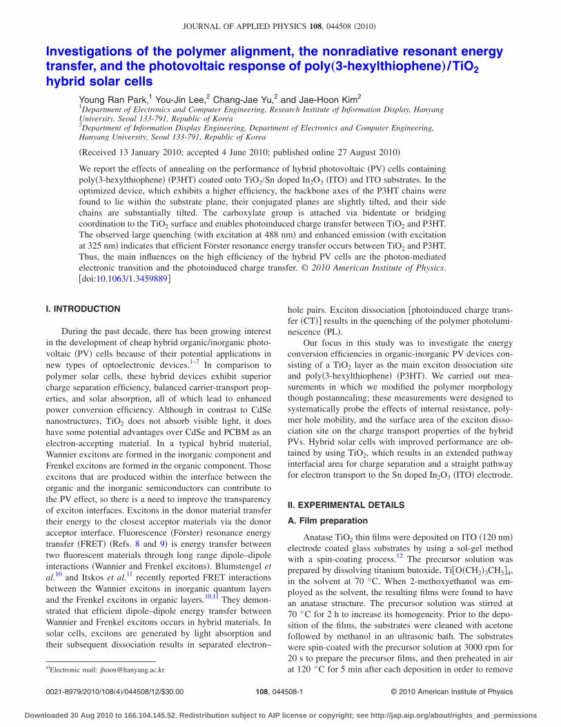
Figure 3 shows the out-of-plane ��=0°� and from theout-of-plane ��=0°� to the in-plane ��=90°� XRD patternsof the �-2� scans obtained for grazing incidence with normalXRD �GIXD� and HRGIXD. Figure 3�a� shows the �100�reflection and its higher order reflections, which correspondto the side-chain lamellar stacking distance. The presence ofonly �l00� reflections indicates that the main chains �theP3HT backbones� have a tendency to orient parallel to theTiO2 and ITO surfaces. In the in-plane ��=90°� �-2� scans,the reciprocal space is probed in the z direction �qz, where qis the scattering vector and z is perpendicular to the samplesurface�, and therefore planes parallel to the surface can beinvestigated with these measurements. The transformationbetween the measured angles and reciprocal space was per-formed by using the following expression, where is thewavelength and 2� is the diffraction angle:
q =2
d=
4
sin�2�
2� . �1�
In Figs. 3�b�–3�d�, only meridional �100�, �200�, and �300�reflections can be distinguished at q=0.37 Å−1 �d
TABLE I. Comparison of the PV parameters and rms roughnesses of the P3HT-based and TiO2 /P3HT-baseddevices under 100 mW /cm2.
Annealed conditionsof the P3HT film
ITO /TiO2 /P3HT /Au ITO/P3HT/Au ITO /TiO2 /P3HT /Au
In air in a box furnaceat 150 °C for 1 h
In a N2 atmosphere witha pressure of approximately100 mTorr in a quartz tubefurnace at 240 °C for 1 h
Jsc �mA /cm2� 0.141 0.212 0.460Voc �V� 0.325 0.370 0.57Pmax �mW /cm2� 0.02 0.03 0.11Fill factor �FF� 0.395 0.425 0.428Efficiency �%� 0.02 0.03 0.11Rs �� cm2� 121.6 74.5 61.6rms roughness �nm� 9.11 3.82 4.72
FIG. 2. The forward bias voltage above Voc as a function of the currentdensity for the ITO /TiO2 /P3HT /Au devices with various annealing condi-tions: �a� with TiO2 in air; �b� without TiO2 in N2; �c� with TiO2 in N2. Theincident light intensity was 100 mW /cm2 �1 sun�.
044508-3 Park et al. J. Appl. Phys. 108, 044508 �2010�
Downloaded 30 Aug 2010 to 166.104.145.52. Redistribution subject to AIP license or copyright; see http://jap.aip.org/about/rights_and_permissions
=16.80 Å�, q=0.74 Å−1 �d=8.48 Å�, and q=1.11 Å−1 �d=5.65 Å�, which correspond to the stacking periodicity par-allel to the long axis of the alkyl side chains. The plane �=30° and 60° results in a Bragg reflection at q=1.52 Å−1
�d=4.12 Å�, which is assigned to the �010� line correspond-ing to the – �inter-chain� stacking of the P3HT chains.The low intensity of this �010� reflection peak is indicative ofdefects in the close packing of the chains in this direction.Note that this reflection is superimposed on a broad halooriginating from the glass substrate. The presence of the re-flection corresponding to the �100� plane in both diffractionpatterns seems to indicate that this plane, although perpen-dicular to the long axis, can adopt different orientations withrespect to rotation around this axis. It might originate from apopulation of nanorods with a 90° rotation around their longaxis with respect to the other ones present in the layer �see
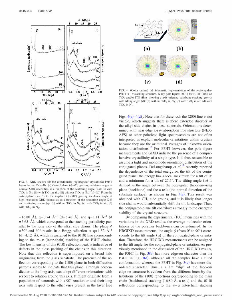
Figs. 4�a�–4�d��. Note that for these rods the �200� line is notvisible, which suggests there is more extended disorder ofthe alkyl side chains in these nanorods. Orientations deter-mined with near edge x-ray absorption fine structure �NEX-AFS� or other polarized light spectroscopies are not ofteninterpreted as explicit molecular orientations within crystalsbecause they are the azimuthal averages of unknown orien-tation distributions.13 For P3HT however, the pole figuremeasurements and GIXD indicate the presence of a compre-hensive crystallinity of a single type. It is thus reasonable toassume a tight and monomode orientation distribution of theconjugated planes. DeLongchamp et al.13 recently reportedthe dependence of the total energy on the tilt of the conju-gated plane: the energy has a local maximum for a tilt of 0°and a minimum for a tilt of 27.5°. The tilting angle ��� isdefined as the angle between the conjugated thiophene-ringplane �backbone� and the a-axis �the normal direction of thesubstrate surface�, as shown in Fig. 4�a�. This result wasobtained with CH3 side groups, and it is likely that longerside chains would substantially shift the tilt landscape. Thus,the conjugated-plane tilt contributes strongly to the energeticstability of the crystal structure.
By comparing the experimental �100� intensities with thevariations in the XRD results, the average molecular orien-tations of the polymer backbones can be estimated. In theHRGIXD measurements, the angle � �from 0° to 90°� corre-sponds to the tilt angle ��� of the conjugated-plane orienta-tion. Therefore, the HRGIXD measurements can be assignedto the tilt angle for the conjugated-plane orientation. As pre-viously mentioned in the discussion of the HRGIXD results,the P3HT in Fig. 3�b� has more edge-on character than theP3HT in Fig. 3�d�, although all the samples have a tiltedconformation, whereas the P3HT in Fig. 3�c� has more dis-ordered character. Thus, a slight “slip” of the face-on/edge-on structure is evident from the different intensity dis-tributions of the �100� reflections corresponding to the mainchain �backbones� stacking �16.80 Å, a-axis� and the �010�reflections corresponding to the – interchain stacking
FIG. 3. XRD spectra for the directionally regioregular crystallized P3HTlayers in the PV cells. �a� Out-of-plane ��=0°� grazing incidence angle atnormal XRD intensities as a function of the scattering angle �2��: �i� withTiO2 in N2; �ii� with TiO2 in air; �iii� without TiO2 in N2. ��b�–�d�� From theout-of-plane ��=0°� to the in-plane ��=90°� grazing incidence angle athigh resolution XRD intensities as a function of the scattering angle �2��and scattering vector �q�: �b� without TiO2 in N2; �c� with TiO2 in air; �d�with TiO2 in N2.
FIG. 4. �Color online� �a� Schematic representation of the regioregular-P3HT – stacking structure. X-ray pole figures 001 for P3HT �100� onTiO2 and/or ITO films showing c-axis oriented backbone-stacking growthwith tilting angle ���: �b� without TiO2 in N2; �c� with TiO2 in air; �d� withTiO2 in N2.
044508-4 Park et al. J. Appl. Phys. 108, 044508 �2010�
Downloaded 30 Aug 2010 to 166.104.145.52. Redistribution subject to AIP license or copyright; see http://jap.aip.org/about/rights_and_permissions

�4.12 Å, b-axis� in the variation in the geometric modes. Theoverlap of the electronic wave function within the lamellaeplanes should result in increased intralayer mobility in theP3HT films. On the other hand, electronic states distrib-uted outside the polymer surface can overlap with the electronic wave functions of an overlayer molecular material,which can provide efficient CT in the heterojunction struc-tures used in polymer devices.
The persistence length of regiorandom P3HT has beenreported to be 2.1 nm,14 but since regioregularity defectscause twists in polymer chains, the persistence length ofhighly regioregular P3HT should be significantly longer. Thehigh molecular weight polymer molecules are approximately80 nm long. The molecules are expected to have multiplebends along their length. We believe that P3HT forms smallordered areas separated by disordered regions and that longchains connect the ordered areas and prevent charge carriersfrom being trapped by the disordered boundary regions bycreating a continuous pathway through the film. The PV cellswith TiO2 annealed in a N2 atmosphere exhibit a higher ef-ficiency when no alkyl chain stacking is observed �Fig. 3�d��.Hole delocalization and interchain interactions �– stack-ing� can benefit carrier transport in conjugated regioregularP3HT thin films.15 However, the presence of insulating sidechains in the surface region can be detrimental to the CTbetween the polymer backbone and the overlayer molecules.
Alkyl-substituted P3HT has a backbone of sequentiallybonded thiophene rings with linear alkane chains attached totheir sides. In thin films, they self-assemble into lamellae; alayer-packing motif where planar backbones stack inlamellae vertically segregated from lamellae of side chainshas been developed by comparing typical unit-cell dimen-sions to molecular dimensions,16–18 and is generally ac-cepted. Two critical but poorly characterized aspects of thecrystal structure are the conjugated-plane tilt and the alkaneside-chain configuration. In the lamellar motif, the conju-gated planes must be roughly vertical �orthogonal to thelamella� so that they can stack face-to-face within a quasi-two-dimensional sheet. However, a variety of conjugated-plane tilts and many possible side-chain configurations dis-tinguished by varying the tilt and the degree ofinterdigitation are consistent with this layer-packing motifand the available diffraction data. The carrier transport de-pends critically on the intermolecular overlap of the carrierband orbitals, which is controlled by the conjugated-planespacing and tilt.
In recent calculations for two-dimensional poly-thiophene sheets, significant rotation of the polymer back-bone was predicted to be energetically favorable. This tilt isimportant because it governs the interactions between neigh-boring chains, and therefore has a significant effect on theband structure and the optical properties of the material. Thepresent study performed structural investigations of P3HTlayers grown epitaxially on TiO2�200� and ITO�440� crystalsurfaces. The crystal alignment and the epitaxial relation-ships between the substrates and thin-film crystals were de-termined experimentally by using XRD techniques.
Figure 4�a� shows a schematic diagram of the molecularstructure of the P3HT thin films on the glass substrate, as
determined from the XRD data results. This model was con-firmed by the presence of a symmetric lattice plane, as ob-served in the multiple reflections �00l�, l=1–3.
Figures 4�b�–4�d� show the x-ray pole figures 001 forP3HT �100� on TiO2 and ITO films, which indicate the pres-ence of c-axis oriented backbone-stacking growth with a tilt-ing angle. The pole figures were determined for steps of �and �, where � is the polar �or radial� angle and � is theazimuthal angle �in-plane rotation�. Since each pole figure ismeasured at a constant diffraction angle �constant �q��, itgives the spatial distribution of a certain net plane. The planenormals are called poles, and therefore peaks in pole figuresare known as areas of enhanced pole density. For a set ofpole figures performed for different net planes, the completeorientation distribution of the crystallites and their orienta-tion relative to the substrate �epitaxial relationship� can bedetermined unambiguously. For all the PV cells, the polefigure 001 of P3HT �100� has a diagonal shape over thepolar angle range 0°–10°. The peak for �440� ITO �2�=50.65°� interferes with that of �200� TiO2 �2�=48.07°�.The pole figure shown in Fig. 4 also contains four peak po-sition directions. These peak positions are due to the TiO2
and ITO films. The backbone axes are within the substrateplane, the conjugated planes are slightly tilted, and the sidechains are substantially tilted. The displacement of the sidechains from the conjugated plane is speculative but consis-tent with their known tilt. This effect could be due to theinferior crystal quality that results from a relaxation of theP3HT layer, which generates dislocations �increasing leakagecurrent and recombination�.
The morphology and microstructure of polymeric semi-conductors and especially of semicrystalline polymers playvery important roles in the charge transport in these devices.In particular, defects, grain boundaries, and disordered re-gions contribute to localize states. Figure 5 shows AFM im-ages of P3HT surfaces in following PV cells: �a� withoutTiO2 in N2, �b� with TiO2 in air, and �c� with TiO2 in N2. InTable I, the P3HT of Fig. 5�c� has a smooth surface with arms roughness �Rrms� of 4.72 nm, whereas the P3HT surfacein Fig. 5�b� is rougher �Rrms=9.11 nm�. This result is con-sistent with that of Fig. 5�a�, which was prepared under simi-lar conditions and has a rather smoother surface �Rrms
=3.82 nm�. In particular, we have demonstrated the correla-tion between FF and surface roughness at the charge sepa-ration interface.
A P3HT �Fig. 6�c�� film deposited uniformly onto anITO �Fig. 6�a�� substrate �120 nm� was coated with a TiO2
�Fig. 6�b�� film. Figure 6 shows a cross-section and a top-view of the resulting TiO2 /P3HT hybrid layers under theFESEM. The hybrid film is uniform over the entire substrate.The cross-section clearly shows that P3HT interpenetratesinside the TiO2 grain and occupies nearly the entire spacesurrounding the grains. The P3HT deposit above the TiO2
film forms a solid film approximately 50 nm thick that canpotentially prevent electron back transfer and reduce darkcurrent. Our structural observations, including with XRD andAFM, show that the ordered P3HT lamella is nanocrystal-line, and that the size of the ordered regions is 10 nm.18–20 InFig. 6�c�, the FESEM results show that the average crystal-
044508-5 Park et al. J. Appl. Phys. 108, 044508 �2010�
Downloaded 30 Aug 2010 to 166.104.145.52. Redistribution subject to AIP license or copyright; see http://jap.aip.org/about/rights_and_permissions

lite size is approximately 20 nm, and that there are substan-tial regions of disordered material. Other growth conditionsresult in a more needlelike microstructure.21
It is well known that TiO2 has three natural phases: ana-tase, rutile, and brookite.22 Anatase is tetragonal �D19 4h�with two formula units per unit cell and six Raman activemodes �A1g+2B1g+3Eg�. The Raman spectrum in Fig. 7�a�shows that the film is composed of the anatase phase. Fiveclear and strong peaks at 144, 194, 395, 518, and 638 cm−1
arise from the optical vibration modes Eg��6�, Eg��5�,B1g��4�, A1g+B1g��2+�3�, and Eg��1�.23 Figure 7 pro-vides further information about the interface between P3HTand TiO2 coated on the ITO electrode, respectively. Smalldifferences can be found between the Raman lines of P3HTon the TiO2 and ITO substrates. The band assignments of theRaman spectra of polythiophene have been reported indetail.27 The characteristic peaks of CuSuC ring deforma-tion �672 and 726 cm−1�, C uH symmetric in-plane bend-ing �1090 cm−1�, C�uC�� inter-ring stretching�1200 cm−1�, C uC � ring stretching �1379 cm−1�,C�vC ring stretching �1445 cm−1�, and C�vC stretch-ing �anti� �1506 cm−1�, are all present in both spectra. As canbe seen in Fig. 7, the most intense band of the spectrumobtained by excitation at 514 nm appears at approximately1445 cm−1, which is assigned to the total symmetric in-phase vibration of the thiophene rings spreading over thewhole polymer chain. This band is associated with the con-jugated polymer segments in a neutral state. The relativeintensities of the other characteristic peaks were normalized,with the highest peak in both spectra at 1445 cm−1. The
Raman bands are related to oxidized species such as radicalcations �polaron�, dications �dipolaron�, and the kinks are ofincreased intensity.24 In the inset in Fig. 7, the band at1420 cm−1 �Q1� is attributed to the symmetric stretchingmode �CvC� of radical cations and the kink bands�1455 cm−1, D bands� are associated with distorted parts ofpolymer chains.24 A few papers have discussed the changesin the chain structures of conducting polymers during heat-ing and cooling processes, and have reported that the thermalstabilities and conformational transition behaviors of oxi-dized �doped� and neutral �undoped� conducting polymersare different. It is believed that such changes in chain struc-ture are due to extrinsic defects, such as oxygen. During the
FIG. 5. �Color online� AFM images of the P3HT layers in the PV cells: �a�without TiO2 in N2; �b� with TiO2 in air; �c� with TiO2 in N2. The dimen-sions of the images are 10�10 �m2.
FIG. 6. FESEM images for the ITO /TiO2 /P3HT /Au devices: �a� ITO; �b�pure TiO2; �c� P3HT �annealed at 240 °C for 1 h under a N2 atmosphere ata pressure of approximately 100 mTorr in the quartz tube furnace�. The insetin �c� shows cross-section images of the PV cells.
044508-6 Park et al. J. Appl. Phys. 108, 044508 �2010�
Downloaded 30 Aug 2010 to 166.104.145.52. Redistribution subject to AIP license or copyright; see http://jap.aip.org/about/rights_and_permissions

postannealing of the TiO2 /P3HT layer in air, oxygen attacksand is diffused into P3HT mainly through the first CuHbond of the alkyl chains; a series of steps then leads to chainbreakage. In addition, the significant oxidation effects inP3HT can be explained in terms of the hole doping of thedonor levels, which can occur even after postannealing. It isreasonable to conclude that the oxidized species in P3HT aremainly present as radical cations. It is thought that dications�1400 cm−1 ,Q2� are not formed in P3HT. Therefore, theseexperimental results demonstrate that single charges arestored in polaron states and that two charges are expected tobe stored in two independent polar states rather than in asingle bipolaron for long polymer chains. The inset in Fig.7�b� shows a small Q1 mode, even though P3HT was an-nealed at 240 °C for 1 h in a N2 atmosphere with a pressureof approximately 100 mTorr. The ITO electrode was depos-ited by sputtering at a substrate temperature of 200 °C,which is lower than the postannealing temperature of P3HT�see Fig. 6�a� and Ref. 25�. Thus the oxygen in the ITOelectrode diffuses into P3HT during the postannealing of theP3HT /TiO2 layer, which induces oxidation effects in P3HT.
A very weak CvO stretching vibration mode is evidentat 1730 cm−1. The presence of this mode can be explained interms of the contributions of nonadsorbed molecules and freeligands to the spectrum. Thus, the relatively strong band at1730 cm−1 in Figs. 7�b� and 7�c� indicates the contributionsof nonadsorbed molecules and free carboxylic-acid ligandsduring the postannealing of P3HT. These ligands can formH-bonds with the surface. During the postannealing of theTiO2 /P3HT layer in air, the oxygen attacks and is diffusedinto P3HT. The overall features of this spectrum are similarto those of the Raman spectrum of neutral P3HT, except forthe bands at 1010, 1188, 1306, and 1608 cm−1. An interest-ing feature of the Raman spectrum of P3HT is the presenceof a band at 1188 cm−1, which arises from C�uC�� inter-ring stretching vibrations of distorted parts of the polymer.26
The change in the polarizability moment due to distortedC�uC�� inter-ring stretching is not parallel but at an angleto the thiophene ring.
The bands in the Raman spectrum due to adsorbed car-
boxylate appear in the range 1150–1600 cm−1. Four bandsdue to carboxylate are likely to be present: CuO stretching�coupled with ring stretches� peaks at 1010 cm−1,1306 cm−1, 1379 cm−1, and 1608 cm−1, which correspondto the TiuOuC, CuOH �coupled CuO�, COO− sym-metric �carboxylate� stretching, and carboxyl group vibrationmodes, respectively. Carboxy groups can coordinate withmetal ions in various ways as follows: physical adsorptionvia hydrogen bonding, bidentate chemical bonding forma-tion, and bridging. Metal ions can interact with either of thetwo oxygen atoms of the �COO−� group.27 In fact, recentcalculations and experiment evidence show that the dissocia-tive adsorption of carboxyl groups at defect sites leads to amuch larger redshift in the TiO2 excitation energy than mo-lecular adsorption. These results are in agreement with thoseobtained from the absorbance measurements.
Note that the P3HT samples in the three devices wereannealed under different conditions. The vibration near1379 cm−1 was assigned to the C uC � ring stretchingmode and COO− symmetric stretching. However, no band isevident at 1608 cm−1 in Fig. 7�d�. Therefore, the comparisonof Figs. 7�b� and 7�c� with Fig. 7�d� shows that the Ramanspectroscopic changes during the postannealing process re-sult from reactions between P3HT and the oxygen or mois-ture in the air. We suggest that the 1379 cm−1 mode is con-tributed to by both COO− symmetric stretching and C uC �ring stretching. In contrast to Figs. 7�b� and 7�c�, in whichbands due to the 1608 cm−1 vibration mode are present, the1608 cm−1 vibration mode is not evident in Fig. 7�d�, whichmeans that free carboxylic-acid groups are not present. Inaddition, since a very weak line �CvO, at 1730 cm−1� anda strong line �COO− symmetric stretching, at 1379 cm−1� arepresent, it can be concluded that the attachment of the car-boxy groups to TiO2 occurs via bidentate or bridging bonds.Importantly, two lines �1608 and 1730 cm−1� of the Ramanspectra appear at precisely the same frequencies in the infra-red spectra. The disordered conformational state can be con-verted to an ordered conformational state by lowering thetemperature. This change elongates the conjugation length ofthe polymer chain and causes a redshift in the optical absorp-tion of P3HT. The decrease in the intensity of the 1445 cm−1
band is possibly due to the change in the conformationalstate of the P3HT layers, because this is the only band asso-ciated with the conjugated P3HT segments. However, theformation of surface CT complexes commonly leads to sen-sitization with respect to visible light. Visible laser Ramanspectroscopy is a convenient technique for studying theseabsorption elements because the laser probe photo-excitesthe CT complexes, which leads to an enhancement of theRaman scattering phenomenon �resonance Raman scattering,RRS�. The P3HT films produce a very strong visible lightabsorption band with a maximum located at approximately500 nm, which is related to the →� electronic transition.Therefore, when excited at 514 nm �close to 500 nm�, theresonance effect enhances the Raman lines of P3HT.
The FT-Raman spectra in Fig. 8 are not characterized asRaman spectra because they were recorded during laser ex-citation at 1064 nm; there is no absorption in this region inthe UV-vis spectra of P3HT on the TiO2 and ITO films.
FIG. 7. Micro-Raman spectra of the TiO2 films and PV cells obtained byusing Ar laser excitation at 514 nm: �a� pure TiO2; �b� with TiO2 in air; �c�without TiO2 in N2; �d� with TiO2 in N2.
044508-7 Park et al. J. Appl. Phys. 108, 044508 �2010�
Downloaded 30 Aug 2010 to 166.104.145.52. Redistribution subject to AIP license or copyright; see http://jap.aip.org/about/rights_and_permissions
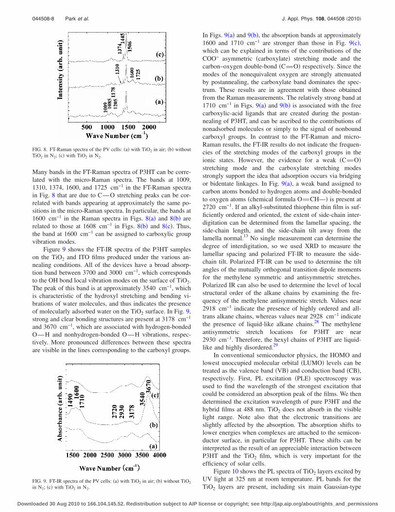
Many bands in the FT-Raman spectra of P3HT can be corre-lated with the micro-Raman spectra. The bands at 1009,1310, 1374, 1600, and 1725 cm−1 in the FT-Raman spectrain Fig. 8 that are due to CuO stretching peaks can be cor-related with bands appearing at approximately the same po-sitions in the micro-Raman spectra. In particular, the bands at1600 cm−1 in the Raman spectra in Figs. 8�a� and 8�b� arerelated to those at 1608 cm−1 in Figs. 8�b� and 8�c�. Thus,the band at 1600 cm−1 can be assigned to carboxylic groupvibration modes.
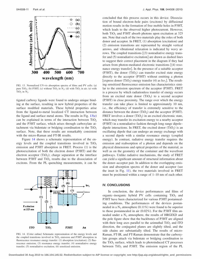
Figure 9 shows the FT-IR spectra of the P3HT sampleson the TiO2 and ITO films produced under the various an-nealing conditions. All of the devices have a broad absorp-tion band between 3700 and 3000 cm−1, which correspondsto the OH bond local vibration modes on the surface of TiO2.The peak of this band is at approximately 3540 cm−1, whichis characteristic of the hydroxyl stretching and bending vi-brations of water molecules, and thus indicates the presenceof molecularly adsorbed water on the TiO2 surface. In Fig. 9,strong and clear bonding structures are present at 3178 cm−1
and 3670 cm−1, which are associated with hydrogen-bondedOuH and nonhydrogen-bonded OuH vibrations, respec-tively. More pronounced differences between these spectraare visible in the lines corresponding to the carboxyl groups.
In Figs. 9�a� and 9�b�, the absorption bands at approximately1600 and 1710 cm−1 are stronger than those in Fig. 9�c�,which can be explained in terms of the contributions of theCOO− asymmetric �carboxylate� stretching mode and thecarbon–oxygen double-bond �CvO� respectively. Since themodes of the nonequivalent oxygen are strongly attenuatedby postannealing, the carboxylate band dominates the spec-trum. These results are in agreement with those obtainedfrom the Raman measurements. The relatively strong band at1710 cm−1 in Figs. 9�a� and 9�b� is associated with the freecarboxylic-acid ligands that are created during the postan-nealing of P3HT, and can be ascribed to the contributions ofnonadsorbed molecules or simply to the signal of nonboundcarboxyl groups. In contrast to the FT-Raman and micro-Raman results, the FT-IR results do not indicate the frequen-cies of the stretching modes of the carboxyl groups in theionic states. However, the evidence for a weak �CvO�stretching mode and the carboxylate stretching modesstrongly support the idea that adsorption occurs via bridgingor bidentate linkages. In Fig. 9�a�, a weak band assigned tocarbon atoms bonded to hydrogen atoms and double-bondedto oxygen atoms �chemical formula OvCHu� is present at2720 cm−1. If an alkyl-substituted thiophene thin film is suf-ficiently ordered and oriented, the extent of side-chain inter-digitation can be determined from the lamellar spacing, theside-chain length, and the side-chain tilt away from thelamella normal.13 No single measurement can determine thedegree of interdigitation, so we used XRD to measure thelamellar spacing and polarized FT-IR to measure the side-chain tilt. Polarized FT-IR can be used to determine the tiltangles of the mutually orthogonal transition dipole momentsfor the methylene symmetric and antisymmetric stretches.Polarized IR can also be used to determine the level of localstructural order of the alkane chains by examining the fre-quency of the methylene antisymmetric stretch. Values near2918 cm−1 indicate the presence of highly ordered and all-trans alkane chains, whereas values near 2928 cm−1 indicatethe presence of liquid-like alkane chains.28 The methyleneantisymmetric stretch locations for P3HT are near2930 cm−1. Therefore, the hexyl chains of P3HT are liquid-like and highly disordered.29
In conventional semiconductor physics, the HOMO andlowest unoccupied molecular orbital �LUMO� levels can betreated as the valence band �VB� and conduction band �CB�,respectively. First, PL excitation �PLE� spectroscopy wasused to find the wavelength of the strongest excitation thatcould be considered an absorption peak of the films. We thendetermined the excitation wavelength of pure P3HT and thehybrid films at 488 nm. TiO2 does not absorb in the visiblelight range. Note also that the electronic transitions areslightly affected by the absorption. The absorption shifts tolower energies when complexes are attached to the semicon-ductor surface, in particular for P3HT. These shifts can beinterpreted as the result of an appreciable interaction betweenP3HT and the TiO2 film, which is very important for theefficiency of solar cells.
Figure 10 shows the PL spectra of TiO2 layers excited byUV light at 325 nm at room temperature. PL bands for theTiO2 layers are present, including six main Gaussian-type
FIG. 8. FT-Raman spectra of the PV cells: �a� with TiO2 in air; �b� withoutTiO2 in N2; �c� with TiO2 in N2.
FIG. 9. FT-IR spectra of the PV cells: �a� with TiO2 in air; �b� without TiO2
in N2; �c� with TiO2 in N2.
044508-8 Park et al. J. Appl. Phys. 108, 044508 �2010�
Downloaded 30 Aug 2010 to 166.104.145.52. Redistribution subject to AIP license or copyright; see http://jap.aip.org/about/rights_and_permissions

peaks at 370 nm, 397 nm, 419 nm, 450 nm, 541 nm, and 660nm �shown in Fig. 10 and in the inset in Fig. 10� denoted A,B, C, D, E, and F, respectively. The emission bands around370 nm are assigned to direct recombination from the CB tothe VB, and vary only slightly between the different inter-faces and TiO2 surfaces. The presence of the emission bandat 397 nm reflects the surface status, and in particular theincomplete surface passivation. When compared to the peaknear 370 nm due to the TiO2 surface �see Fig. 10�c��, theTiO2 interface �see Fig. 10�b�� is clear but the peak at 397nm due to the TiO2 interface is feeble, which shows that theinterface states have been destroyed, especially the TiuOHstates. UV light can easily change the TiO2 surface electronicstructure. Most of the TiO2 is destroyed and slowly replacedby TiuOH, as has been confirmed by photoinduced superhydrophilicity studies, so the capture of photoinduced elec-trons by TiO2 decreases accordingly and the intensity of thepeak at 397 nm decreases. It is expected that indirect recom-bination will stem from surface recombination via oxygenvacancies. PL peaks are present at 419 and 450 nm in Figs.10�a� and 10�c� but these peaks are not present in �b�. Someauthors have attributed this flat band to the trapping of exci-tonic PL peaks by surface states and defects; this band is alsoeasily affected by factors related to the surface. The peak at419 nm is due to the trapping of excitonic PL peaks bysurface states. Bulk impurities arise mainly in the form ofoxygen defects and can act as the centers of indirect recom-bination, so the peak at 450 nm is thought to be due toindirect recombination via oxygen defects.30,31 In the inset inFig. 10, the broad emission band at 541 nm is composed oftwo Gaussian-type bands. These bands are attributed to theradiative recombination of surface oxygen vacancies andself-trapped excitons.32 It is expected that annealing at hightemperatures will break the binding between oxygen and ti-tanium in the TiO2 films and then pull oxygen out of thesample. The broad luminescence band centered at 660 nm isassociated with the recombination of electrons from the CB
edge with holes trapped at interstitial Ti3+ sites.33 In particu-lar, there is a significant quenching of PL in the layeredsample as compared with that found in pure TiO2. The PLquenching in the TiO2 /P3HT bilayer film might be due tofollowing two different effects: �i� photoinduced back CTand �ii� resonance energy transfer between energy species inthe excited state, due to the overlap between the emissionand absorption spectra. Such resonance energy transfer de-pends on the intermolecular distance and the spectral overlapas well as on the mutual transition dipole orientation. For CTto occur, the binding energy of the photogenerated excitonshould be smaller than the difference between the electronaffinities of the participating donor and acceptor materials,when corrected for the Coulomb attraction between the sepa-rated charges. In addition, the yield of the PL emission in thebilayer decreases substantially in the presence of TiO2. Thisdecreased PL intensity indicates that charge separation oc-curs at the interface between the two materials. This separa-tion produces a charge-separated state consisting of an elec-tron on the TiO2 and a hole on the polymer, which isresponsible for the TiO2 emission quenching.
Figure 11 shows plots of the PL spectra obtained for theP3HT samples by using a spectrometer with an HeuNelaser excitation source �=325 nm�. It can be seen that allthe samples produce broad photoemissions with followingtwo peaks: one at 645 nm and the other at 690 nm. TheTiO2 /P3HT bilayer produces two electroluminescencepeaks, at 580 and 640 nm; the first peak is more intense thanthe second. The negligible differences in the position andintensity of these emission peaks can be explained in termsof electroluminescence. In Fig. 11, it can be seen that thephotoemissions of the hybrid samples exhibit higher lumi-nescence intensity than that of pure P3HT. However, thestrongest PL enhancement arises for �b� TiO2 /P3HT �in N2�,
FIG. 10. Normalized PL spectra of the TiO2 emission areas in the PV cellsobtained by using HeuNe laser excitation at 325 nm: �a� with TiO2 in N2;�b� with TiO2 in air; and �c� pure TiO2.
FIG. 11. Normalized PL spectra of the P3HT emission areas in PV cellsobtained by using HeuNe laser excitation at 325 nm: �a� pure TiO2; �b�with TiO2 in N2; �c� without TiO2 in N2; �d� with TiO2 in air; �e� P3HT. Theupper inset shows the absorption spectra �open circles� for P3HT and the PLspectra �closed squares� for TiO2. The closed square emission curve wasexcited at 488 nm.
044508-9 Park et al. J. Appl. Phys. 108, 044508 �2010�
Downloaded 30 Aug 2010 to 166.104.145.52. Redistribution subject to AIP license or copyright; see http://jap.aip.org/about/rights_and_permissions

whereas the PL intensities for �c� P3HT �in N2� and �d�TiO2 /P3HT �in air� did not increase significantly. In thesehybrid films, no blueshift was obtained; blueshifts would beexplained by a reduction in the polymer conjugation chainlength. Although PL enhancement in these systems has rarelybeen discussed, one suggestion is that the increased PL in-tensity of such P3HT layers can be explained in terms of thelarge absorption coefficient of TiO2. This interpretation canbe seen for instance in Ref. 34, where the authors recentlydiscussed PL enhancement in TiO2 /P3HT. This phenomenonwas explained as due to nonradiative FRET �Ref. 9� fromTiO2 to the polymer for excitation at wavelengths of less 350nm. The inset in Fig. 10 shows the region of overlap betweenthe UV-visible absorption of P3HT and the PL spectrum ofTiO2. It can be obvious that the overlapping results could bepossibly transferred between TiO2 and P3HT by means ofFRET. FRET is mediated by dipole–dipole interactions, thestrength of which critically depends on among other influ-ences the spectral overlap between donor �TiO2� emissionand acceptor �P3HT� absorption and on the dipole separationdistance.9,35 Energy alignment is thus needed in order tomaximize the resonant coupling between the inorganic andorganic excitations.36 In Fig. 11, expansion of the 550–850nm region shows that the intensity of P3HT emissions aris-ing from excitation of TiO2 /P3HT at 325 nm is greater thanthat arising from excitation of P3HT at 325 nm. Thus themajority of emissions from TiO2 upon HeuNe laser excita-tion can be attributed to absorption and FRET from the ab-sorbing P3HT. Since the inorganic material and the polymerhave different emission and absorption spectra with someoverlap, the energy could possibly be transferred between thetwo components by means of FRET �Refs. 9 and 37� andphoton recycling effects.38 FRET is a near-field long rangeenergy transfer process that enables excitons to transfer be-tween molecules for distances above 25 nm.39 In the hybriddevice, it is possible for P3HT �donors� to transfer excitonsto neighboring TiO2 �acceptors� close to the donor/acceptorinterface, because a part of the absorption spectrum overlapswith the P3HT emission spectrum.
The inset in Fig. 12 shows the room-temperature UV-visible absorption and PL spectra of TiO2 and P3HT, respec-tively. P3HT produces a broad recombination spectrum witha peak at approximately 600 nm and the spectrum of TiO2
contains a sharp absorption edge at approximately 350 nm.There are no additional absorption peaks in the measuredspectral range. The degree of PL quenching can also provideinformation about the quality of the interconnection of TiO2
and the polymer and the nature of their interface. In Fig. 12,for excitation at 488 nm only the polymer is excited; the PLspectra of the devices contain similar emission features tothat of pure P3HT, which indicates that the luminescencepredominantly results from excitons that radiatively recom-bine in the polymer. However, the yield of the PL emissionin the composites decreases substantially in the presence ofTiO2. This decreased PL intensity indicates that charge sepa-ration occurs at the interface between the two materials. i.e.,a charge-separated state with an electron on the TiO2 and ahole on the polymer is responsible for the polymer emissionquenching. PL quenching provides direct evidence for exci-
ton dissociation; efficient PL quenching is necessary to ob-tain efficient organic solar cells. However, this does not nec-essarily mean that the stronger the PL quenching, the betterthe performance of the solar cells. Similar observations havealso been reported for poly�3-octylthiophene�, which consistsof thiophene rings with large alkyl groups,40 and for MEHP-PPV/CdSe-nanoparticle composite films.41 Rapid chargeseparation at the TiO2 /P3HT interface leads to efficient ex-citon dissociation, and thus results in quenching of the PLefficiency. Thus, the PL quenching results in Figs. 11 and 12indicate the occurrence of photon-mediated electronic transi-tions �FRET� and photoinduced CT, respectively.
In this study, all samples were tested at a constant filmthickness to compare the optical absorption and PL intensi-ties of P3HT and TiO2. Figure 13 shows the UV-vis spectraof the polymer films. In a conjugated polymer, the extent ofconjugation directly affects the observed energy of the –�
transition, which appears as the maximum absorption �max�in its UV-vis spectrum. The spectrum of P3HT contains apeak at 520 nm and two shoulders at 560 and 612 nm, whichare attributed to its crystalline -stacking structure. The red-shifted absorption of P3HT is due to the better chain packinginduced by three-dimensional ordering of the polymerchain,42 which increases the average length and decreases theHOMO–LUMO band gap.43 P3HT in �c� and �d� has a lowerabsorbance than P3HT in �b� and �e�, and the max of P3HTin �c� and �d� is 10 nm blueshifted �from 510 to 500 nm� withrespect to that of P3HT in �b� and �e�. This result can beexplained in terms of a change in the stacking conformationof the polymer structure from high crystallinity to lowercrystallinity, and a reduction in the intraplane and interplanestacking, which causes a poor –� stacking transition andlower absorbance. However, contrary to the peak at 350 nm�in Fig. 13�d��, the slop at 310 nm �in Fig. 13�e�� do notshow any change with pure TiO2 �in Fig. 13�a��. The inves-
FIG. 12. Normalized PL spectra of the P3HT emission areas in PV cellsobtained by using Ar laser excitation at 488 nm: �a� pure TiO2; �b� withTiO2 in N2; �c� without TiO2 in N2; �d� with TiO2 in air; �e� P3HT. Theupper inset shows the absorption spectra �open circles� for TiO2 and the PLspectra �closed squares� for P3HT. The closed square emission curve wasexcited at 488 nm.
044508-10 Park et al. J. Appl. Phys. 108, 044508 �2010�
Downloaded 30 Aug 2010 to 166.104.145.52. Redistribution subject to AIP license or copyright; see http://jap.aip.org/about/rights_and_permissions
tigated carboxy ligands were found to undergo unique bind-ing at the surface, resulting in new hybrid properties of thesurface modified materials. These hybrid properties arisefrom the ligand-to-metal localized CT interaction betweenthe ligand and surface metal atoms. The results in Fig. 13�e�can be explained in terms of the interaction between TiO2
and the P3HT surface, which arises through carboxylate at-tachment via bidentate or bridging coordination to the TiO2
surface. Note, that these results are remarkably consistentwith the micro-Raman and FT-IR results.
Figure 14 shows a schematic representation of the en-ergy levels and the coupled transitions involved in TiO2
emission and P3HT absorption in FRET. Process �1� is thephotoexcitation of both the electron donor �P3HT� and theelectron acceptor �TiO2�; charge separation at the interfacebetween P3HT and TiO2 results due to the dissociation ofexcitons. From the PL quenching measurements, it can be
concluded that this process occurs in this device. Dissocia-tion of bound electron–hole pairs �excitons� by diffusionalmotion results in the formation of free mobile holes in P3HT,which leads to the observed higher photocurrent. However,both TiO2 and P3HT absorb photons upon excitation at 325nm. Note that each of the two materials play the roles of bothdonor and acceptor. In FRET, �1� absorption �excitation� and�2� emission transitions are represented by straight verticalarrows, and vibrational relaxation is indicated by wavy ar-rows. The coupled transitions ��3� nonradiative energy trans-fer and �5� nonradiative excitation� are drawn as dashed linesto suggest their correct placement in the diagram if they hadarisen from photon-mediated electronic transitions ��4� reso-nance energy transfer�. In the presence of a suitable acceptor�P3HT�, the donor �TiO2� can transfer excited state energydirectly to the acceptor �P3HT� without emitting a photon�express donor �TiO2� energy transfer �4� as h�1�. The result-ing sensitized fluorescence emission has characteristics simi-lar to the emission spectrum of the acceptor �P3HT�. FRETis a process by which radiationless transfer of energy occursfrom an excited state donor �TiO2� to a second acceptor�P3HT� in close proximity. The range over which the energytransfer can take place is limited to approximately 10 nm,i.e., the efficiency of transfer is extremely sensitive to thedistance between the donor �TiO2� and the acceptor �P3HT�.FRET involves a donor �TiO2� in an excited electronic state,which may transfer its excitation energy to a nearby acceptor�P3HT� in a nonradiative fashion through long range dipole–dipole interactions. In FRET, the excited donor �TiO2� is anoscillating dipole that can undergo an energy exchange witha second dipole with a similar resonance energy �coupledenergy�. In contrast, radiative energy transfer requires theemission and reabsorption of a photon and depends on thephysical dimensions and optical properties of the material, aswell as on the geometry of the container and the wavefrontpathways. Unlike radiative mechanisms, the study of FRETcan yield a significant amount of structural information aboutthe donor–acceptor pair. In addition to the overlapping emis-sion and absorption spectra of the donor and acceptor �seethe inset in Fig. 11�, the two materials involved in FRETmust be positioned within a range of 1–10 nm of each other.
IV. CONCLUSIONS
In conclusion, the device performances and films oforganic–inorganic hybrid PV cells containing TiO2 andP3HT have been characterized for various P3HT postanneal-ing conditions. The performances of the devices postan-nealed in a N2 atmosphere �0.11%� were found to be superiorto those postannealed in air �0.02%�. For the P3HT film an-nealed under a N2 atmosphere, the results of HRGIXD andthe pole figure show that the backbones of P3HT are alignedwith their long axes parallel to the azimuthal TiO2 and ITOdirection, the conjugated planes are slightly tilted, and theside chains are substantially tilted. The results of micro-Raman, FT-IR, and FT-Raman demonstrate that the carboxy-late groups attach via bidentate or bridging coordination tothe TiO2 surface, which leads to photoinduced CT processesbetween TiO2 and P3HT. The emission region of the PL
FIG. 13. Normalized UV-vis absorption spectra of films and PV cells: �a�pure TiO2; �b� P3HT; �c� without TiO2 in N2; �d� with TiO2 in air; �e� withTiO2 in N2.
FIG. 14. �Color online� Schematic representation of the energy levels andthe coupled transitions involved in TiO2 emission and P3HT absorption influorescence resonance energy transfer: �1� absorption �excitation�; �2� fluo-rescence emission; �3� resonance energy transfer; �4� nonradiative energytransfer; �5� nonradiative excitation; �6� sensitized emission.
044508-11 Park et al. J. Appl. Phys. 108, 044508 �2010�
Downloaded 30 Aug 2010 to 166.104.145.52. Redistribution subject to AIP license or copyright; see http://jap.aip.org/about/rights_and_permissions

spectra of P3HT indicates large quenching �with excitation at488 nm� and enhanced emission �with excitation at 325 nm�.Note that each of the two materials play the roles of bothdonor and acceptor. All these results can be correlated withthe I-V characteristics of the hybrid devices in order to in-terpret the enhanced efficiencies. Our study of the effects ofthe postannealing of the polymer has revealed the occurrenceof resonance energy transfer at the interface between TiO2
and P3HT, which indicates that the efficiency of hybrid PVcells can be enhanced by FRET due to overlap between theemission and absorption spectra.
ACKNOWLEDGMENTS
This research was supported by Samsung ElectronicsCo. Ltd. and the Korea Research Foundation Grant fundedby the Korean Government �MOEHRD� �Grant No. KRF-2008-005-J04104�.
1K. M. Coakley and M. D. McGehee, Chem. Mater. 16, 4533 �2004�.2K. M. Coakley and M. D. McGehee, Appl. Phys. Lett. 83, 3380 �2003�.3A. C. Arango, L. R. Johnson, V. N. Bliznyuk, Z. Schlesinger, S. A. Carter,and H. H. Horhold, Adv. Mater. 12, 1689 �2000�.
4T. J. Savenije, J. M. Warman, and A. Goossens, Chem. Phys. Lett. 287,148 �1998�.
5P. A. van Hal, M. P. T. Christiaans, M. M. Woenk, J. M. Kroon, and R. A.J. Janssen, J. Phys. Chem. B 103, 4352 �1999�.
6L. H. Slooff, M. M. Wienk, and J. M. Kroon, Thin Solid Films 451–452,634 �2004�.
7P. Ravirajan, S. A. Haque, D. Poplavskyy, J. R. Durrant, D. D. C. Bradley,and J. Nelson, Thin Solid Films 451–452, 624 �2004�.
8T. Förster, Ann. Phys. 2, 55 �1948�.9T. Förster, Discuss. Faraday Soc. 27, 7 �1959�.
10S. Blumstengel, S. Sadofev, C. Xu, J. Puls, and F. Henneberger, Phys. Rev.Lett. 97, 237401 �2006�.
11G. Itskos, G. Heliotis, P. G. Lagoudakis, J. Lupton, N. P. Barradas, E.Alves, S. Pereira, I. M. Watson, M. D. Dawson, J. Feldmann, R. Murray,and D. D. C. Bradley, Phys. Rev. B 76, 035344 �2007�.
12Y. R. Park and K. J. Kim, Thin Solid Films 484, 34 �2005�.13D. M. DeLongchamp, R. J. Kline, E. K. Lin, D. A. Fischer, L. J. Richter,
L. A. Lucas, M. Heeney, I. McCulloch, and J. E. Northrup, Adv. Mater.19, 833 �2007�.
14G. W. Heffner and D. S. Pearson, Macromolecules 24, 6295 �1991�.15R. A. Street, J. E. Northrup, and A. Salleo, Phys. Rev. B 71, 165202
�2005�.16T. J. Prosa, M. J. Winokur, and R. D. McCullough, Macromolecules 29,
3654 �1996�.17Z. Bao, A. Dodabalapur, and A. J. Lovinger, Appl. Phys. Lett. 69, 4108
�1996�.18H. Sirringhaus, P. J. Brown, R. H. Friend, M. M. Nielsen, K. Bechgaard,
B. M. W. Langeveld-Voss, A. J. H. Spiering, R. A. J. Janssen, E. W.Meijer, P. Herwig, and D. M. de Leeuw, Nature �London� 401, 685 �1999�.
19R. Azumi, E. Mena-Osteritz, R. Boese, J. Benet-Buchholz, and P. Bauerle,J. Mater. Chem. 16, 728 �2006�.
20B. Grévin, P. Rannou, R. Payerne, A. Pron, and J. P. Travers, Adv. Mater.15, 881 �2003�.
21R. J. Kline, M. D. McGehee, E. N. Kadnaikova, J. Liu, and M. J. Frechet,Adv. Mater. 15, 1519 �2003�.
22P. P. Lottici, D. Bersani, M. Braghini, and A. Montenero, J. Mater. Sci. 28,177 �1993�.
23V. Swamy, A. Kuznetsov, L. S. Dubrovinsky, R. A. Caruso, D. G.Shchukin, and B. C. Muddle, Phys. Rev. B 71, 184302 �2005�.
24F. Chen, G. Shi, J. Zhang, and M. Fu, Thin Solid Films 424, 283 �2003�.25U. Betz, M. Kharrazi Olsson, J. Marthy, M. F. Escolá, and F. Atamny,
Surf. Coat. Technol. 200, 5751 �2006�.26E. A. Bazzaoui, G. Levi, S. Aeiyach, J. Aubard, J. P. Marsault, and P. C.
Lacaze, J. Phys. Chem. 99, 6628 �1995�.27G. B. Deacon and R. J. Philips, Coord. Chem. Rev. 33, 227 �1980�.28M. C. Gurau, D. M. Delongchamp, B. M. Vogel, E. K. Lin, D. A. Fischer,
S. Sambasivan, and L. J. Richter, Langmuir 23, 834 �2007�.29R. A. MacPhail, H. L. Strauss, R. G. Snyder, and C. A. Elliger, J. Phys.
Chem. 88, 334 �1984�.30J. Liqiang, Q. Yichuna, W. Baiqia, L. Shudana, J. Baojianga, Y. Libina, F.
Weia, F. Hongganga, and S. Jiazhongb, Sol. Energy Mater. Sol. Cells 90,1773 �2006�.
31B. S. Liu, X. J. Zhao, and L. P. Wen, Mater. Sci. Eng., B 134, 27 �2006�.32H. Tang, H. Berger, P. E. Schmid, and F. Levy, Solid State Commun. 87,
847 �1993�.33R. Sanjinés, H. Tang, H. Berger, F. Gozzo, G. Margaritondo, and F. Lévy,
J. Appl. Phys. 75, 2945 �1994�.34Y. T. Lin, T. W. Zeng, W. Lai, C. W. Chen, Y. Y. Lin, Y. S. Chang, and W.
F. Su, Nanotechnology 17, 5781 �2006�.35T. Virgili, D. G. Lidzey, and D. D. C. Bradley, Adv. Mater. 12, 58 �2000�.36D. Basko, G. C. LaRocca, F. Bassani, and V. M. Agranovich, Eur. Phys. J.
B 8, 353 �1999�.37Y. Liu, M. A. Summers, C. Edder, J. M. J. Fréchet, and M. D. McGhee,
Adv. Mater. 17, 2960 �2005�.38Y. Liu, M. A. Summers, S. R. Scully, and M. D. McGehee, J. Appl. Phys.
99, 093521 �2006�.39A. Martí, L. Cyadra, and A. Luque, Physica E 14, 150 �2002�.40A. Watanabe, T. Kodaira, and O. Ito, Chem. Phys. Lett. 273, 227 �1997�.41Y. Y. Lin, C. W. Chen, J. Chang, T. Y. Lin, I. S. Liu, and W. F. Su,
Nanotechnology 17, 1260 �2006�.42Y. Kim, S. Cook, S. M. Tuladhar, S. A. Choulis, J. Nelson, J. R. Durrant,
D. D. C. Bradley, M. Giles, I. McCulloch, C. S. Ha, and M. Ree, NatureMater. 5, 197 �2006�.
43P. J. Brown, D. S. Thomas, A. Köhler, J. S. Wilson, J. S. Kim, C. M.Ramsdale, H. Sirringhaus, and R. H. Friend, Phys. Rev. B 67, 064203�2003�.
044508-12 Park et al. J. Appl. Phys. 108, 044508 �2010�
Downloaded 30 Aug 2010 to 166.104.145.52. Redistribution subject to AIP license or copyright; see http://jap.aip.org/about/rights_and_permissions