Investigation on the Freckle Formation Affected by ...
1
Investigation on the Freckle Formation Affected by Geometry Features in Directionally Solidified Superalloy Components J. Hong a, b , D. Ma a, , F. Wang a, c , J. Wang b , B. Sun b A. Bührig-Polaczek a a Foundry Institute, RWTH Aachen University, Aachen 52072, Germany; b State Key Laboratory of Metal Matrix Composites, Shanghai Jiao Tong University, Shanghai 20040, P R China; c State Key Laboratory of Solidification Processing, Northwestern Polytechnical University, Shaanxi, Xi’an 710072, P R China; Corresponding author. Tel.: +49 (0) 241 80-95883; Fax.: +49 (0) 241 80-92276; E-mail address: [email protected] (D. Ma). Experimental Alloy: CM247 LC Withdrawal rate: 1.67×10 -3 cm s -1 Pouring temperature: 1773K Heater temperature: 1723K Shell Mould material: Alumina with Silica binder Atmosphere: vacuum (10 -2 Pa) The geometrical effect The simulation of the local thermal field was performed by ProCAST software under the same condition of experiments. Summary The main conclusions are as follows: (1) The freckling flow was influenced by the sloping surface of specimens during the directional solidification. The outward sloping surface would cut-off the convection channel while the inward sloping surface would enhance the thermosolutal convection. (2) Based on temperature measurements, the geometrical features affect the local thermal condition of specimens. (3) The geometrical feature of the components can strongly change the reservoir and flow condition for thermosolutal convection, which can more effectively affect the freckle formation than the local thermal condition. (4) The geometrical effect is an individual influence factor of freckle formation as well as alloy chemistry and solidification condition. Local thermal condition The measurement point T1 was placed in the base of the inverted conical frustum, T2 was placed in the top of the inverted conical frustum, T3 was placed in the top of the conical frustum and T4 was placed in the base of the conical frustum. Fig.4: The cooling curves of (a) specimen with an expansive cross-section and (b) specimen with a contracting cross-section (a) (b1) (b2) (b3) r h θ T3 T4 T1 T2 Fig.1: Geometry of specimens constructed by conical frustum with a sloping angle of 30 degree Fig.2: Procedure of single-crystal solidification: (a) ceramic shell mould, (b) melt pouring, (c) directional solidification and (d) Photograph of casting components Freckle occurrence (a) In the partial enlargements (right), the freckle chain appears as a gray and long trail parallel to the direction of gravity. (b) Some freckle spots were observed periodically only on the bottom of each outward sloping geometrical unit. The freckle chain stops soon after the initial position with the outward sloping surface on the specimen. (c) A sufficient supporting volume supplies the possibility of thermosolutal convection which results in freckle formation. The incubation distance ∆Z should be a critical length for freckle incubation. ∆Z-incubation zone Fig.3: The macro-etched surface and cross-section: (a) cylindrical bar with uniform cross-section (diameter of 19 mm), (b) specimen with expansive cross-section and (c) specimen with contractive cross-section (b) (a) Thermocouple T1 T2 T3 T4 Freckle? Yes No Yes No Ṫ (K/s) 0.061 0.047 0.073 0.061 GL (K/mm) 3.65 2.83 4.37 3.64 Tab. 1: Calculation results of the temperature gradient and the cooling rate of the investigated superalloy CM247 LC Fig.5: Simulated shape of the liquidus-isotherm (TL) when passing through a unit of geometry (a) and (b) by ProCAST software Fig.6: Schematics of the longitudinal sections showing the reservoir zones (broken lines) supporting the freckling flow (arrows) along the surface. (a) Bar geometry with vertical surface; (b) Expanding geometry with outward sloping surface; (c) Contracting geometry with inward sloping surface 0049
Transcript of Investigation on the Freckle Formation Affected by ...
Investigation on the Freckle Formation Affected by Geometry Features in Directionally Solidified Superalloy Components
J. Hong a, b, D. Ma a, , F. Wang a, c, J. Wang b, B. Sun b A. Bührig-Polaczek a aFoundry Institute, RWTH Aachen University, Aachen 52072, Germany; b State Key Laboratory of Metal Matrix Composites, Shanghai Jiao Tong University, Shanghai 20040, P R China; c State Key Laboratory of Solidification Processing, Northwestern Polytechnical University, Shaanxi, Xi’an 710072, P R China; Corresponding author. Tel.: +49 (0) 241 80-95883; Fax.: +49 (0) 241 80-92276; E-mail address: [email protected] (D. Ma).
Experimental Alloy: CM247 LC Withdrawal rate: 1.67×10⁻³ cm s-1
Pouring temperature: 1773K Heater temperature: 1723K Shell Mould material: Alumina with Silica binder Atmosphere: vacuum (10-2Pa)
The geometrical effect The simulation of the local thermal field was performed by ProCAST software under the same condition of experiments.
Summary The main conclusions are as follows: (1) The freckling flow was influenced by the sloping surface of specimens during the directional solidification. The outward sloping surface would cut-off the convection channel while the inward sloping surface would enhance the thermosolutal convection. (2) Based on temperature measurements, the geometrical features affect the local thermal condition of specimens. (3) The geometrical feature of the components can strongly change the reservoir and flow condition for thermosolutal convection, which can more effectively affect the freckle formation than the local thermal condition. (4) The geometrical effect is an individual influence factor of freckle formation as well as alloy chemistry and solidification condition.
Local thermal condition The measurement point T1 was placed in the base of the inverted conical frustum, T2 was placed in the top of the inverted conical frustum, T3 was placed in the top of the conical frustum and T4 was placed in the base of the conical frustum.
Fig.4: The cooling curves of (a) specimen with an expansive cross-section and (b) specimen with a contracting cross-section
(a) (b1) (b2) (b3)
r
h θ
T3
T4
T1
T2
Fig.1: Geometry of specimens constructed by conical frustum with a sloping angle of 30 degree
Fig.2: Procedure of single-crystal solidification: (a) ceramic shell mould, (b) melt pouring, (c) directional solidification and (d) Photograph of casting components
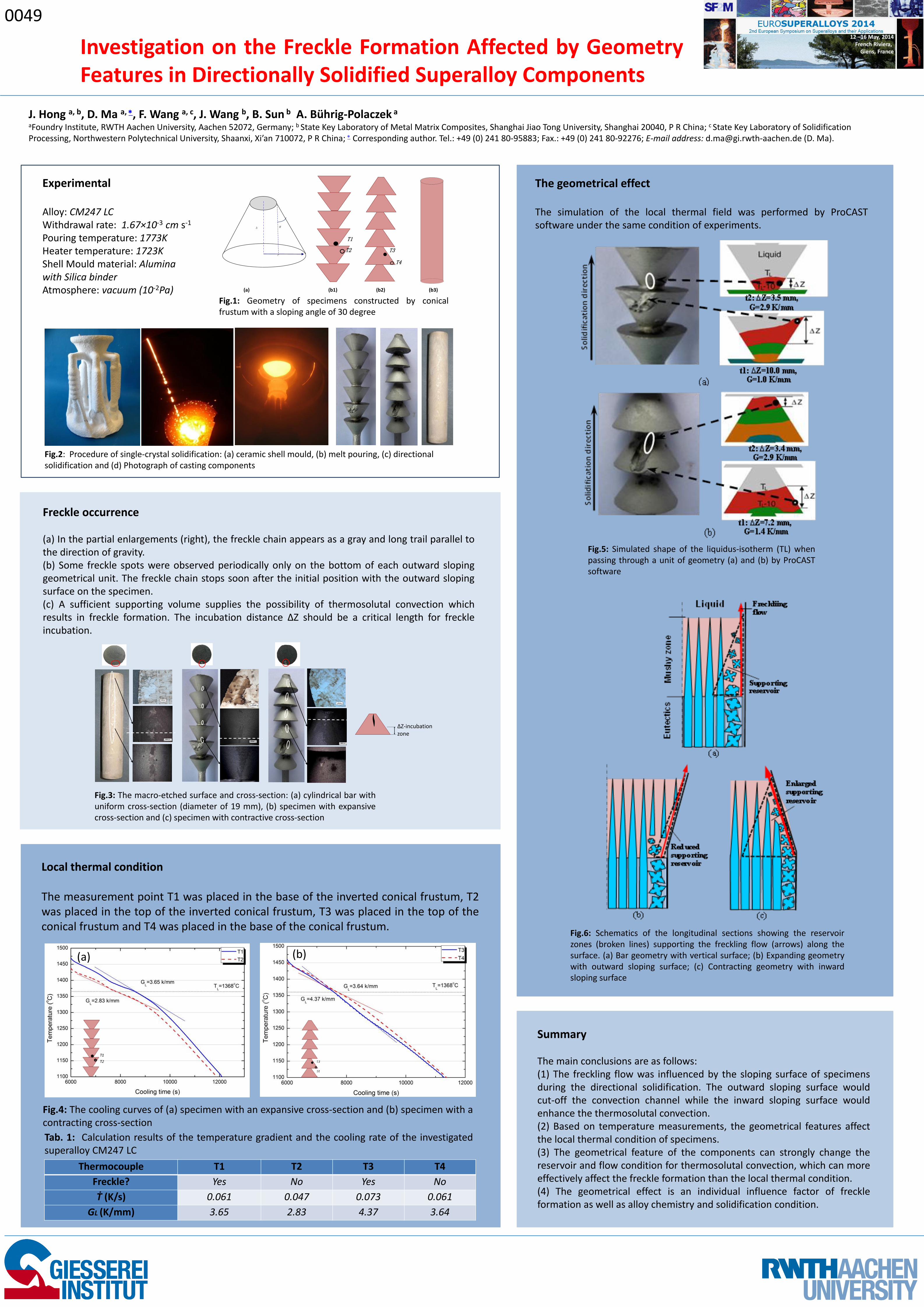
Freckle occurrence (a) In the partial enlargements (right), the freckle chain appears as a gray and long trail parallel to the direction of gravity. (b) Some freckle spots were observed periodically only on the bottom of each outward sloping geometrical unit. The freckle chain stops soon after the initial position with the outward sloping surface on the specimen. (c) A sufficient supporting volume supplies the possibility of thermosolutal convection which results in freckle formation. The incubation distance ∆Z should be a critical length for freckle incubation.
∆Z-incubation zone
Fig.3: The macro-etched surface and cross-section: (a) cylindrical bar with uniform cross-section (diameter of 19 mm), (b) specimen with expansive cross-section and (c) specimen with contractive cross-section
(b) (a)
Thermocouple T1 T2 T3 T4
Freckle? Yes No Yes No
Ṫ (K/s) 0.061 0.047 0.073 0.061
GL (K/mm) 3.65 2.83 4.37 3.64
Tab. 1: Calculation results of the temperature gradient and the cooling rate of the investigated superalloy CM247 LC
Fig.5: Simulated shape of the liquidus-isotherm (TL) when passing through a unit of geometry (a) and (b) by ProCAST software
Fig.6: Schematics of the longitudinal sections showing the reservoir zones (broken lines) supporting the freckling flow (arrows) along the surface. (a) Bar geometry with vertical surface; (b) Expanding geometry with outward sloping surface; (c) Contracting geometry with inward sloping surface
0049