Investigation on Novel Polymer Filter Medium for ...
156
0 Investigation on Novel Polymer Filter Medium for Filtration of Automotive Lubricants Sergiy Botov Supervisor: Dr. Robert Wooley Dissertation Submitted to the Department of Mechanical Engineering, University of Sheffield in Partial Fulfilment of the Requirements for the Degree of Master of Philosophy May 2016
Transcript of Investigation on Novel Polymer Filter Medium for ...

0
Investigation on Novel Polymer Filter Medium
for Filtration of Automotive Lubricants
Sergiy Botov
Supervisor: Dr. Robert Wooley
Dissertation Submitted to the Department of Mechanical Engineering,
University of Sheffield in Partial Fulfilment of the Requirements for the
Degree of
Master of Philosophy
May 2016

1
Abstract
At present in all countries with developed automotive industry a lot of attention is
given to the improvement of the efficiency of automobile engines. The continuous
increase in the power output of the engines along with the introduction of turbo-
supercharging have significantly affected the loading on moving parts of engines
and their sensitivity from the abrasive polluting impurity. Ensuring necessary
resource and reliability of engines, the application of the engine oil with the high
level of operation characteristics have imposed increased requirements for
lubrication systems of engines.
Work on further improvement of lubrication systems includes optimization of
hydraulic and design features of units of lubrication systems and the increase in the
efficiency of oil filters. Economic, regulatory and environmental concerns are
forcing vehicle operators to re-evaluate oil filtration practices. Fleet operators can
choose from various options, including conventional disposable paper oil filters,
centrifugal separators and in-line cleanable oil filters. To guide decisions about
filtration practices, this research compares the performance, serviceability,
economics and environmental impact of these options.
The aim of this research is to investigate the influence of the polymer filter media on
the quality of filtration of automotive lubricants and to demonstrate advantages and
unique features of the polymer filter media. The outcome of this research establishes
relevant characteristics of the novel polymer filter media, extensively tested for
filtration of automotive lubricants.
It demonstrates different impacts on oil filtration provided by the polymer filter
media used in oil filters and compares its performance against the paper filter media
used in tests of oil filters and also in both polymer and paper oil filtration systems.
The application of the polymer filter media results in a significant reduction of the
wear of engine moving parts and an extended oil drain intervals. The analysis of
laboratory tests and obtained data, demonstrate that polymer oil filters have greater
filtration efficiency and also greater contaminant retention capacity in comparison
with conventional paper oil filters.
Based on the knowledge gained here various recommendations have been given on
the potential future work related to this topic.

2
Acknowledgements
I wish to express my sincere appreciation to my supervisors, Professor Chris Wilson
and Doctor Robert Woolley for their patience, guidance and support through my
time at the University of Sheffield. I appreciate the opportunities they provided for
me to be involved in a number of relevant research projects.

3
Table of Contents
Abstract………………………………………………………………...1
Acknowledgments……………………………………………………...2
Table of Contents……………………………………………………....3
List of Tables…………………………………………………………...6
List of Figures………………………………………………………….8
List of Symbols………………………………………………………..11
Chapter
1. Introduction...................................................................................................12
1.1 Background and Motivation.…………………………………………..12
1.2 Aims, Objectives and Methodologies.…………………………………14
1.3 An Overview of the Research.…………………………………………15
2. Literature Review………………………………………………………….17
2.1 Engine oil and lubricant systems, classification of lubricant
systems of the internal combustion engines..................................................17
2.2 Contamination of oil and its influence on reliability of the engine
operation…………………………………………………………………...20
2.3 Filtration of oil, classification of methods of filtration..........................23
2.4 Bases of the theory and calculation of filtration systems.......................24
2.5 Features of designs of filters…………………………….……………..27
2.5.1 Full-flow filters............................................................................27
2.5.2 By-pass and combined filters.......................................................30
4
2.6 Conclusions. Setting goals of the research.....................................45
3. Experimental Techniques……………………………………………….....47
3. Research methods of oil filtration systems and their further
improvement……………………………………………………………….47
3.1. Laboratory and engine bench tests……………………………………47
3.1.1 Methods of determination of pore size of filtering media...……47
3.1.2 Methods of the assessment of the filtering materials using
artificial contaminants…………………..……………………………49
3.2 Engine bench tests of oil filtration systems …………………………...50
3.2.1 Analysis of methods of engine and bench tests………………...50
3.3 Conclusions.............................................................................................51
4. Filtering Material Properties……………………………………………….52
4. Research of filtering materials and designs of oil filters………………..52
4.1 Research of filtering materials used in full-flow oil filters……………52
4.1.1 The filtering elements from polymers………….........................52
4.1.2 The filtering elements from paper…….......................................55
4.2 Conclusions.............................................................................................60
5. Theory……………………………………………………………………....61
5. Calculation and analytical researches of oil filtration systems….……....61
5.1 Research of schemes of cleaning systems...............................................61
5.2 Research of efficiency of oil filtration and reliability of protection
of bearings of the engine against contamination impurity.......................61
5.3 Conclusions..............................................................................................71

5
6. Discussion…………………………………………………………………..76
6. Research and development of combined polymer oil filtration
systems for the internal combustion engines……………………………79
6.1 Laboratory, engine bench tests of by-pass oil filters..............................79
6.2 Engine bench tests of combined polymer oil filtration systems.............86
6.2.1 Engine tests of Cummins ISB e-4 diesel engine.........................87
6.2.1.1 Physical and chemical properties of engine oil………………88
6.2.1.2 Quantity of deposits retained by oil filters and their component
structure…….…………………………………………………………95
6.2.1.3 Efficiency of tested oil filters...……………………………….96
6.2.2 Engine tests of VW 1.2TSI petrol engine with various oil
filtration systems…………………………………………………….108
6.2.2.1 Physical and chemical properties of engine oil……………...109
6.2.2.2 Quantity of deposits retained by filters and analysis of
efficiency of oil filtration systems………………………………….110
6.3 Conclusions...........................................................................................121
7. Conclusions and Future work……………………………………………..123
7.1 Conclusion............................................................................................123
7.2 Future work...........................................................................................124
8. References…………………………………………………………………125
Appendix 1. List of UK Patents…………………………………………………..130

6
List of Tables
Table 2.1 Key parameters of full-flow oil filters for engines……………….…….33
Table 2.2 Types and applicability of Triple-R filters……………………………..39
Table 2.3 Design parameters of by-pass filters……………………………………39
Table 3.1 The mode of engine tests……………………………………………….50
Table 3.2 Physical and chemical indicators of oil………………………………...51
Table 3.3 Quantity of deposits of contamination impurity in centrifuges………...51
Table 4.1 Porosity of filtering materials…………………………………………..53
Table 4.2 Results of laboratory tests of filtering materials………………………..56
Table 5.1 Coefficient of elimination of the centrifuge…………………………….65
Table 6.1 Physical and chemical properties of filtering materials………………...77
Table 6.2 Characteristics of filtering materials……………………………………78
Table 6.3 Researched factors and levels of filter elements variation……………..80
Table 6.4 The mode (cycles) of diesel engine tests……………………………….87
Table 6.5 Quantity of the deposits retained by filters and centrifuge……………..95
Table 6.6 Balance of total contamination impurity in diesel engine……………...97
Table 6.7 Balance of oxyacids in diesel engine…………………………………...99
Table 6.8 Balance of asphaltenes in diesel engine……………………………….100
Table 6.9 Balance of deposits from carbenes and carboides in diesel engine…...101
Table 6.10 Balance of deposits of carbenes, carboides and unburnables…………102
Table 6.11 Balance of unburnables in diesel engine………………………………103
Table 6.12 Coefficient of oil filtration.………………………………………........106
Table 6.13 Impurity of pistons in diesel engine, in points………………………...106

7
Table 6.14 Wear of the rings by weight, grams…………………………………..107
Table 6.15 Wear of the inserts of bearings (thickness) micron…………………...107
Table 6.16 Wear of the necks of cranked shaft, micron…………………………..107
Table 6.17 Wear of the sleeves of cylinders, micron……………………………..108
Table 6.18 Component composition of tested oil and sludge from filters………..110
Table 6.19 Balance of total contamination impurity in diesel engine……………119
Table 6.20 Impurity of piston group parts of VW 1.2 TSI petrol engine………...120
Table 6.21 Average wear of the piston rings on radial thickness, micron………..120
Table 6.22 Average wear of the piston rings by weight, grams…………………..120
Table 6.23 Average wear of the sleeves of cylinders, micron……………………121
Table 6.24 Average wear of the necks of cranked shaft, micron…………………121
Table 6.25 Average wear of the inserts of cranked shaft on thickness, micron…..121

8
List of Figures
Figure 2.1 Diagram of oil system flow …………………………………………...21
Figure 2.2 Engine lubrication system …………………………………………….21
Figure 2.3 Diagram of spin-on filter arrangement………………………………...28
Figure 2.4 Main types of full-flow oil filters with filtering elements……………..29
Figure 2.5 Oil flow through full-flow oil filter……………………………………29
Figure 2.6 Oil flow through full-flow oil filter……………………………………31
Figure 2.7 Design of Donaldson spin-on filter……………………………………31
Figure 2.8 Design of Fleetguard spin-on filter……………………………………32
Figure 2.9 Design of Mobil spin-on filter…………………………………………32
Figure 2.10 Design of Fleetguard spin-on filter (depth type)…………..…………..34
Figure 2.11 Diagram of by-pass filter arrangement………………………………...35
Figure 2.12 Design of Fleetguard by-pass with combination elements…….……....35
Figure 2.13 Design of Volvo by-pass depth absorption filter………………………37
Figure 2.14 Refilco oil filter and its hydraulic characteristic………………………38
Figure 2.15 Thermo King EMI 3000 oil filter and its hydraulic characteristic…….41
Figure 2.16 Design of Megatrol by-pass filter……………………………………...41
Figure 2.17 Design of Fleetguard by-pass filter……………………………………42
Figure 2.18 Design of Trple-R by-pass filter……………………………………….42
Figure 2.19 Micronscientific B32 by-pass filter………………………………........42
Figure 4.1 Images of filtering materials…………………………………………...54
Figure 4.2 FRAM paper filter……………………………………………………..55
Figure 4.3 Polymer DC 0.9 filters…………………………………………………55

9
Figure 4.4 Hydraulic characteristics of filters…………………………………….57
Figure 4.5 Hydraulic characteristics of relief valves of oil filters…………...……57
Figure 4.6 Characteristics of contamination of oil filters…………………………58
Figure 4.7 Change of oil consumption through filtering partitions of filters...........58
Figure 4.8 Dependence of change of oil consumption through filtering
partitions with opened relief valve of DC 0.9 filter...……………........59
Figure 4.9 Reliability of protection of bearings provided by PFM 1, PFM 2 and DC
0.9 oil filters..……………………………………………….…………59
Figure 5.2 Dependences of intensity of oil filtration Q on size of
particles of contamination , RPM = 2200, T = 95°C……...................67
Figure 5.3 Dependence of intensity of oil filtration Q on size of particles of
contamination , RPM = 1200, T = 95°C……………………………..68
Figure 5.4 Dependence of intensity of oil filtration Q on size of particles of
contamination , RPM = 1200, T = 95°C………………......................69
Figure 5.5 Dependence of intensity of oil filtration Q on size of particles of
contamination , RPM = 1200, T = 60°C……………….....................70
Figure 5.6 Dependence of probability of penetration of impurity particles
in bearings of cranked shaft bearings and reliability of protection N
bearing from size of particles , RPM = 2200, T = 95°C…………….72
Figure 5.7 Dependence of probability of penetration of impurity particles in
bearings of cranked shaft bearings and reliability of protection N
bearings from size of particles , RPM = 2200, T = 60°C…………..73
Figure 5.8 Dependence of probability of penetration of impurity particles in

10
bearings of cranked shaft bearings and reliability of protection N
bearings from size of particles , RPM = 1200, T = 95°C………….…74
Figure 5.9 Dependence of probability of penetration of impurity particles in
bearings of cranked shaft bearings and reliability of protection N
bearings from size of particles , RPM = 1200, T = 60°C….…………75
Figure 6.1 Surface of response (ABCD) function Y1=f(X1,X2).………………….83
Figure 6.2 Surface of response (ABCD) function Y2=f(X1,X2).....……………….84
Figure 6.3 Surface of response (ABCD) function Y3=f(X3,X4).....…………….…85
Figure 6.4 Image of engine test bench…………………………………………….88
Figure 6.5 Physical and chemical properties of Cummins engine oil…………….89
Figure 6.6 Physical and chemical properties of Cummins engine oil…………….90
Figure 6.7 Physical and chemical properties of Cummins engine oil…………….91
Figure 6.8 Physical and chemical properties of Cummins engine oil…………….92
Figure 6.9 Physical and chemical properties of Cummins engine oil…………….93
Figure 6.10 Dependence of drop of pressure in full-flow filter (FFF)………...…..105
Figure 6.11 Images of combined polymer filters with by-pass element…………..111
Figure 6.12 Physical and chemical properties of VW engine oil………………..112
Figure 6.13 Physical and chemical properties of VW engine oil…………............113
Figure 6.14 Physical and chemical properties of VW engine oil…………………114
Figure 6.15 Physical and chemical properties of VW engine oil…………………115
Figure 6.16 Physical and chemical properties of VW engine oil………………....116
Figure 6.17 Physical and chemical properties of VW engine oil…………………116
Figure 6.18 Physical and chemical properties of VW engine oil………………....117

11
List of Symbols
Х0 and Хк concentration of contamination impurity in oil before and after tests;
Gм, Gуr, Gn weight of the oil being in crankcase, burned and taken during tests;
gm quantity of contamination impurity in oil;
gyr quantity of contamination impurity in burned-down oil;
gn quantity of contamination impurity in samples of oil;
Хср average concentration of contamination impurity in oil;
Х3 concentration of dry phase of contamination impurity;
G3 quantity of products of contamination retained by filters and centrifuges;
g3, g3 ∑ quantity of contamination impurity (dry phase), retained by each filter and
all filters;
g1 total of contamination impurity found in oil;
pR radius of internal surface of rotor;
r0 internal radius of layer of liquid in rotor;
angular speed of rotation of rotor;
the working volume of the rotor ( 2
0
2 rRPh p ), where h - average height of
rotor);
size (diameter) of impurity particles;
21 и density of particle and oil ( 21 );
Q volume of oil consumption through centrifuge per min/hrs;
dynamic viscosity of oil.

12
Chapter 1 – Introduction
1.1. Background and Motivation
At modern rates of engine oil consumption there is need to achieve the extended use
of the engine oil. Along with an improvement in design of engines, optimization of
capacity of a filtration system and reduction of oil consumption in oil smoke,
considerable reduction of the oil use could be achieved through the application of
highly effective combined oil filtration systems, leading to extended oil life cycles.
It was found that properties of the engine oil do not considerably change chemically
and worsen as a result of the use of the engine oil. In fact there is an increase in
content of the following pollutant substances: soot, water, sulphur, metallic and non-
metallic particles, which result in fast ageing of the engine oil and therefore its
replacement and it was also concluded that the application of existing methods of oil
filtration and improved oils with high content of additives do not allow to
significantly increase lifespan of the engine oil.
There have been a number of large scale field trials carried out in Europe and USA
funded by respective governments and the objectives of these trials were to validate
efficiency of various oil filtration systems and filters as well as demonstration of the
engine oil being used for significantly longer periods of time.
For instance in 2003 in USA under the U.S. Department of Energy FreedomCAR &
Vehicle Technologies Program “Oil Bypass filter Technology Evaluation” the field
trials were conducted by Idaho National Engineering and Environmental Laboratory
Transportation Technology and Infrastructure Department.
Their published “Oil Bypass Filter Technology Evaluation” report details the
completed fleet evaluation of an oil bypass filter technology. Eight four-cycle diesel-
engine buses used to transport INEEL employees on various routes have been
equipped with oil bypass filter systems from the puraDYN Corporation. The bypass

13
filters were reported to have engine oil filtering capability of <1 micron and a built-
in additive package to facilitate extended oil-drain intervals. Tested eight buses have
accumulated 259,398 test miles. This represented an avoidance of 21 oil changes,
which equates to 740 quarts (185 gallons) of oil not used or disposed of. Results of
the trials allowed to validate the extended oil-drain intervals, an oil-analysis regime
evaluated the fitness of the engine oil for continued service by monitoring the
presence of necessary additives, undesirable contaminants, and engine-wear metals.
Similarly in Germany field trials were conducted under the programme "Tribology"
related to research projects aiming to increase the engine oil change interval with
inclusion in the oil filtration system of the additional by-pass filter with a high
retaining capacity. These trials were carried out using public buses over a few years.
Public buses were operated in "stop and go" heavy duty conditions with installed
additional by-pass filters and obtained results demonstrated that inclusion of by-pass
filters allows to improve technical condition of engines and also significantly
increase engine oil change interval up to 60-70 thousand km.
Clean oil is vital to an engine performance and its durability. The engine oil must
lubricate, cool and clean the inner engine components as it circulates. However in
order to remain effective it must be continuously filtered. Most engines are fitted
with spin-on filters which were introduced to the market in1960. Since then spin-on
filters have been used in most of automobile engines as they have been designed to
be rugged, durable and inexpensive it is mainly due the fact that only paper filter
media has been used, however these oil filters do not provide sufficient level of the
engine oil filtration and therefore the engine oil has a limited lifespan and typically
replaced every 10,000-12,000 miles, while in USA the engine oil, for instance in
PLG cars, is replaced every 3,000-5,000 miles.
Published results of field trials in Europe and USA clearly demonstrated that the
engine oil has capacity to last significantly longer, provided the efficiency of
filtration exceeds performance of conventional paper filtering media used in oil

14
filters and therefore there is need for introduction of advanced filtering materials,
improved filters or filtration systems.
Ideally it should be an oil filter with superior filtering ability and retaining capacity,
has the ability to improve engine longevity, increase maintenance intervals and
results in significant financial savings over the life of the vehicle. Extending an
engine’s oil drain interval while maintaining the same engine wear resolves around
the durability of the engine oil additive package, retaining capacity and micron
filtering ability of an oil filter.
This requires development of novel types of filtering media with greater filtration
capabilities of providing extended use of the engine oil and outperforming existing
filtering media in all other technical aspects, which is the main motivation driving
this work.
1.2 Aims, Objectives and Methodologies
The aim of this project is to investigate the influence of the combined polymer
oil filtration system on cleaning of automotive lubricants, used in internal
combustion engines. Several key objectives need to be achieved, which are:
1. to analyse existing experience related to the methods of researches and
features of design of oil filtration systems used in internal combustion
engines;
2. to carry out laboratory and engine bench tests of various oil filtration
systems, in order to obtain the reliable assessment of the influence of the
oil cleaning system on the wear and contamination of moving parts,
physical and chemical indicators of engine oil and service life of filters;
3. to determine and demonstrate the possibility of the use of polymer full-
flow oil filters in internal combustion engines, resulting in improved oil
filtration, extended life span of engine oil and reduced wear of moving
parts of the engine;

15
4. to determine reliability of protection of bearings of the engine in different
operating modes using various oil filtration systems, including paper and
polymer full-flow filters, by-pass filters and by-pass centrifuge;
5. to investigate the structural change in balance of components of
contamination impurity present in the engine oil retained by oil filters,
tested in diesel and petrol engines, using various oil filtration systems;
6. to demonstrate by results of this research the efficiency of combined
polymer oil filtration system and its suitability for the application in full-
flow and by-pass oil filters.
For engine bench tests of paper and polymer oil filters and filtration systems
the following types of the internal combustion engines were used: diesel
engine Cummins ISB e-4 and petrol engine VW 1.2 TSI.
1.3 An overview of the Research
The dissertation begins with an in-depth literature review to provide extensive
background information to support the topic discussed throughout the research.
Necessary laboratory and bench tests are conducted as part of the project to
generate a comprehensive data set to characterize performance of various oil
filtration systems under operating conditions. Detailed discussion and analysis
are presented based on the results of carried out various tests via analytical
methods. Finally appropriate conclusions are drawn with regards to future work.
The whole dissertation is divided into the following chapters:
Chapter 1: A brief introduction is given to a practical problem faced in
the automotive industry, which also highlights the importance of this
study. Detailed objectives and methods used, along with the structure of
the dissertation are presented.
Chapter 2: This chapter provides a comprehensive literature review with
regards to the following key topics: theory and application of the engine
oil filtration and lubrication systems, oil contamination and its influence

16
on reliability of engine operation, bases of theory and calculation of
filtering systems.
Chapter 3: Details about the experimental setup are presented in this
chapter. Principles, functions, working procedures, modification of
polymer composition and chemical formulation of the polymer media
are introduced respectively. An overview is given to the filtering
materials tested with respect to their pores structure and types of filter
media.
Chapter 4: In this chapter, results obtained from a series of laboratory
tests are presented. Results are divided into two parts regarding two
filtering materials tested. Filtering characteristics of each material in
various conditions of tests are compared and summarised.
Chapter 5: Analytical researches of various oil filtration systems and
researches of the efficiency of oil filtration are presented in this chapter.
Chapter 6: This chapter presents the results obtained from engine bench
tests of oil filters in the various conditions and from engine cycling tests
to see the impact of filtering materials on the quality of oil filtration.
Chapter 7: Conclusions are drawn based on the results and discussions in
previous chapters. This chapter also provides recommendations for the
future work in this area.

17
Chapter 2 – Literature Review
2.1 Engine oil and lubrication system, classification of lubrication systems of
internal combustion engines
In recent years along with further improvements in design of automobile engines, an
increase of their technological level and reliability, there has been a substantial
increase in quality of the engine oil, which is one of the basic functional elements of
the internal combustion engine. Irrespective of the type of the engine and its design
features, the main functions of the engine oil are [1]:
lubrication of internal parts
providing cooling of the engine by transferring heat
sealing piston ring - cylinder bore interface
absorbing contaminants
suspension of wear particles
protection of engine parts from corrosion
suspension of soot that forms as a result of combustion.
The engine oil should also have the high stability at oxidation and watering and
provide reliable start-up of the engine in low temperatures conditions.
Compliance of the oil quality to ISO Standards and OEM requirements specifically
related to the engine oil, which are aggravated by the presence of various types and
designs of internal combustion engines. The design of the sleeve assembly of the
engine and especially value of its average effective pressure, defining break of
crankcase fumes, is decisive in definition of level of the oil antioxidant ability.
For instance, for diesel engines the engine oil is required with significantly improved
detergency–dispersing properties, than for the petrol engines. The conditions of
engines operation and a quality of diesel and petrol fuels have an extensive impact
on the quality of the engine oil, other factors which should be considered are: an

18
increase in speed of movement of the vehicle and its loading, as the oil temperature
in the sump of the engine reaches 120-1500C [2].
Improved engine oils are available on the market and typically these oils have a
wide range of properties and consist of a large number of various additives that leads
to an increase in their cost. Engine oils are a blend of two components - base oils
and additives [3]. Every type of engine oil is blended in order to meet the required
lubricant performance of relevant ISO standards and specific requirements of
particular application. As a rule the choice of base oil can be mineral, semi-synthetic
or synthetic. Normally off-road diesel engines use mineral engine oil. Semi-
synthetic and synthetic engine oils are used in petrol engines, found in PLG cars,
where longer service intervals and higher operating conditions require more refined
oil. Formulated mix of additives is the difference between producing specific type of
engine oil which meets ISO standards and other type of engine oil that offers
significant performance advantages. Additional additives also enhance the chemical
and physical properties and as a result enable to achieve significant performance
benefits from the engine oil. Various additives used in engine oils are a complex mix
of 10 to 15 different types, they can make up to 25 percent of the formulation,
depending on its quality and application [4].
It was noted [5] [6] that the main criterion determining the life span of the oil is the
content of insoluble in n-Pentane substances.
In order to achieve an increase in the engine capacity there is an increase in quantity
of fresh charge being in the cylinder at the beginning of a compression cycle, known
as pressurization application. However it leads to an increase in the mechanical and
thermal loading and results in applying the following actions:
increase in productivity of water and oil pumps;
increase in efficiency of cooling system;
improvement in the air filtration;

19
application of combined oil filtration systems which provide effective
separation of insoluble impurity.
At the same time, an improvement in oil filtration through an increase in
completeness of elimination of the full-flow filter is restricted by an increase in its
hydraulic resistance resulting in fast opening of the relief valve of the filter and
therefore reduces reliability of protection of bearings, especially during cold start-up
of the engine. Besides an increase in precision of elimination of the filter reduces the
length of its service and increases the operational costs related to the replacement of
filtering elements.
Overall performance of the filtration system depends on the following factors:
structure and purposes of included in the system components and assemblies, their
parameters and connection layout [7].
At present in diesel and petrol engines combined filtration systems are commonly
used, in which under pressure, generated by the oil pump, all slider bearings are
lubricated - radical and connecting rod cranked shaft, camshaft, valve lever,
intermediate gear wheels of distribution of the drive of the oil pump, gear wheels,
shaft of the drive of the high pressure fuel pump, regulator, turbocharger, etc. The
engine oil under pressure is brought to bearings of shaft of the drive of the
distributor of ignition and shaft of the drive of the water pump. Parts of the sleeve
assembly group and others are lubricated through spraying [8].
In some engines auxiliary devices in form of nozzles or openings in parts are applied
for additional supply of the oil through directed jet on various surfaces of friction
such as walls of cylinders, couples valve lever of the drive bar, valve lever of the
core of the valve, etc.
In designs of modern automobile engines, different oil lubrication systems are used.
The knowledge of the general principles of construction, structure and ways of
inclusion of components and assemblies of lubrication systems, enables to improve

20
work related to modernization of existing and development of new types of engines
which meet the requirements of the increased resource, minimum loss of power on
bearings and the drive of various components and assemblies. Based on the analysis
of lubrication systems of various engines it was concluded that systems variety can
be classified by specific for each type characteristics [9].
The oil system flow diagram and the oil lubrication system of the engine, shown in
figures 2.1-2.2 [10].
For normal functioning of lubrication systems there are subsystems which can be
divided into the main system and the auxiliary system. Main subsystems consist of
systems which provide cleaning and maintenance of oil temperature, cooling of
pistons and management of hydraulic parameters through valves, while auxiliary
subsystems provide reduction of delay of intake of engine oil to bearings,
maintenance of oil level, control of parameters and diagnostic of lubrication system.
2.2 Oil contamination and its influence on reliability of engine operation
Advanced engine oils contain complex of additives and possess sufficient washing
and dispersing properties therefore the bulk of contamination impurity has high
degree of dispersion and particles sizes up to 2 microns [11]. The contamination
impurity is divided into two main groups: organic and inorganic. Relevant processes
of engine oil contamination in engines are extensively described in a number of
researches [12].
The organic contamination impurity consists of products of incomplete combustion
of fuel, products of thermal decomposition, oxidation, oil and fuel polymerizations.
Besides water, sulphur and lead compounds which are found in the engine oil. The
inorganic contamination impurity consists of the following: dust particles, products
of operation of cindery additives, particles of the wear and technological
contamination of the engine.

21
Figure 2.1 Oil system flow diagram
Figure 2.2 Engine lubrication system

22
Contamination of the engine oil in diesel engines differs from contamination of the
engine oil in petrol engines, as diesel engines use diesel fuel which has higher soot
content. It was demonstrated [13] that the fulfilled gases of diesel engines contain
the particles with sizes of 0,006-0,5 micron, specific surface of which accounts for
70-90 sq.m/g thus assists the adsorption of products of decomposition of antiwear
and anti-seize additives, reducing thereby antiwear properties of engine oils.
The high content of the soot in the engine oil of diesel engines leads to the
suppression of antiwear properties of zinc dithiophosphate and strengthens the loss
of low-temperature deposits [14] [15], especially as a cooling fluid enters the engine
oil or during operation of engines in cold conditions on short routes with frequent
stops.
Products of the wear of moving parts of the engine, present in the engine oil in the
form of particles of metals, their oxides or metallo-organic compounds, which
negatively influence the oxidizing stability of the oils, strengthen abrasive wear and
suppress an effect of detergency-dispersing additives, assist the growth of acidity
and formation of insoluble substances from hydrocarbons [16].
According to [17] the abrasive particles of the small sizes have the influence on
wear of moving parts when the oil film thickness between parts more than the sizes
of these particles.
Process of oxidizing polymerization of the engine oil and the products, which enter
the engine oil as a result of incomplete combustion of fuel, proceeds with formation
of acid and neutral products: acids, oxyacids, estolides, asphaltene acids, high-
molecular interhalogen-isosteric compounds, asphaltenes, carbenes and carboides
[18].
Contamination of the engine oil occurs in the engine continuously and depends on a
number of factors, such as quality of fuel, oil, design of the engine, modes of its
operation. Especially excessive process of the oil contamination [19] occurs in the

23
engines working in lowered thermal modes and with a low frequency of rotation that
is caused by poor conditions of combustion process and high access of gases to the
base chamber of the engine. Other factors effecting intensity of the oil contamination
are influenced by features of the engine design, engine operation process,
malfunction of the fuel system and wear of parts of sleeve assembly [20].
A number of researches [21] are published and related to the reliability of engine
operation along with the assessment of influence of the oil contamination.
The negative influence of the ageing oil and oil contamination processes have a
negative impact on the following engine operations [22]:
carburization and burning of piston rings and possibly of total loss of their
mobility;
increase in temperature of parts of sleeve assembly;
jamming of valves in directing plugs;
contamination of grids of engine oil receivers, filtering elements and
channels of lubricant systems;
increase in oil viscosity resulting in delay of intake of engine oil to bearings;
abrasive wear of bearings by solid particles of contamination impurity.
Thus, the insoluble contamination impurity having the sizes exceeding the minimum
thickness of the oil film, causes increased wear of moving parts of the engine and
other negative impacts, which in turn reduce the reliability of the engine operation.
At the same time it is desirable to reduce the organic contamination impurity content
in the oil that could considerably increase the length of oil replacement.
2.3 Filtration of oil, classification of methods and means of filtration
The reliable operation of the engine and a long service life of the engine oil cannot
be achieved without the application of effective oil filtration systems.

24
Known methods of the oil filtration are divided into two groups: filtration in the
porous medium and in the force fields. The means of the oil filtration are divided
into two groups: filters such as full-flow, by-pass, combined and powered cleaners
in which gravitational, centrifugal and magnetic force is used.
2.4 Bases of theory and calculation of filtering systems
Theories of calculation of filters and filtering systems are discussed in many reviews
[23] and studies [24].
The pattern of the liquid movement in the porous medium is complex and tend to
change in time in size. The speed of filtration is determined as correlation of
consumption of liquid at rate of throughput to the area of filtering partition,
expressed by the equation
(2.1) F
Q
where - speed of filtration
Q - consumption of liquid at rate
F - area of filtering partition
Hydraulic resistance of filtering partition thus becomes
(2.2) Р= Р1¯ Р2
where Р1 and Р2 - liquid pressure at the entrance and the exit, respectively.
The mode of the stream of liquid in channels of oil filters is characterized by
Reynolds's number of Re100 and is laminar and therefore according to Hagen-
Poiseuille equation the speed of filtration is expressed by the equation

25
(2.3)
Р
l
mРбк уд
п
п
.
4
128
where бn - diameter of pore channel;
ln - length of single pore channel;
m - number of pores channels;
One of the most important characteristics of the porous medium is the coefficient of
porosity determined as correlation of volume of pore Vп to volume of the porous
medium Vп.с.
(2.4) =..
.
.. сп
мсп
сп
п
V
VV
V
V
where Vм - material volume.
Methods of determination of porosity which were used in researches, presented in
studies [25].
The assessment of efficiency of purification of polluting impurity by porous
partition is carried out based on some assumptions:
- the real partition is modeled on cylindrical channels of different diameter and
identical length;
- nature of distribution of pores, doesn't depend on filter operating time;
- movement of working environment laminar for which Hagen-Poiseuille
equation is correct. Provided that the consumption of liquid through pores
will be proportional to fourth degree of its diameter.
With accepted assumptions the general initial coefficient of screening of porous
partition becomes
26
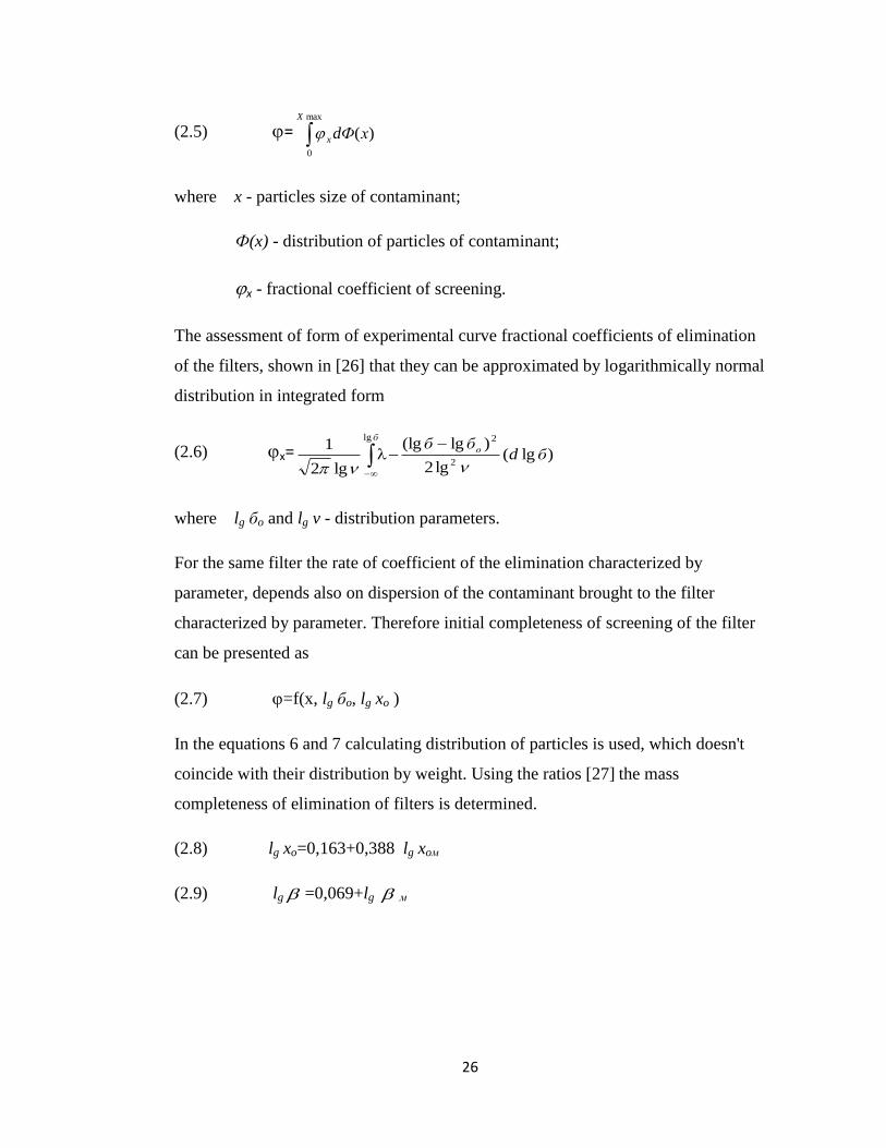
(2.5) = max
0
)(
X
x хdФ
where x - particles size of contaminant;
Ф(x) - distribution of particles of contaminant;
x - fractional coefficient of screening.
The assessment of form of experimental curve fractional coefficients of elimination
of the filters, shown in [26] that they can be approximated by logarithmically normal
distribution in integrated form
(2.6) х= )lg(lg2
)lg(lg
lg2
12
2lg
бdбб о
б
where lg бo and lg v - distribution parameters.
For the same filter the rate of coefficient of the elimination characterized by
parameter, depends also on dispersion of the contaminant brought to the filter
characterized by parameter. Therefore initial completeness of screening of the filter
can be presented as
(2.7) =f(x, lg бo, lg xo )
In the equations 6 and 7 calculating distribution of particles is used, which doesn't
coincide with their distribution by weight. Using the ratios [27] the mass
completeness of elimination of filters is determined.
(2.8) lg xo=0,163+0,388 lg xoм
(2.9) lg =0,069+lg м

27
The development of effective systems of engine oil filtration requires knowledge
and application of bases of the theory of calculation of filtering systems and carrying
out the analysis of features of designs of full-flow, by-pass and combined filters.
2.5 Features of design of oil filters
2.5.1 Full-flow oil filters
The analysis of design of full-flow oil filters, a diagram of a spin-on filter
arrangement is shown in figure 2.3, show that filters can be divided into two main
types: spin-on and cartridge (figure 2.4). The diagram (figure 2.4(1)) shows a
typical spin-on oil filter. The oil flow through an oil filter is shown in figure 2.5.
The full-flow oil filter is standard on most of modern vehicles. Most of oil filters use
the paper filter media, traditional filtering material for full-flow design. The engine
oil that goes through the full-flow filter and continues to lubricate the engine and the
oil filter removes larger particles of contaminant from the engine oil harmful to the
engine. The oil filter provides essential engine protection for maximum cold flow
performance and filter’s lifespan and designed to provide required level of oil
filtration, handle the required flow rate when the engine oil is cold and provide
sufficient dirt retaining capacity.
Mechanical designs employ an element made of the pleated filter paper to entrap and
sequester suspended contaminants. Produced by filter manufacturers automotive oil
filters vary in their design, materials, and construction parts. Full-flow filters that are
made from completely synthetic material except the metal drain cylinders contained
within are much superior and longer lasting than the traditional cellulose and paper
type that still commonly used as filter media. These variables affect the efficiency,
durability and cost of oil filters.

28
Figure 2.3 Diagram of spin-on filter arrangement
(1) Spin-on type

29
(2) Cartridge type
Figure 2.4 Main types of full-flow oil filters
Figure 2.5 Oil flow through a full-flow oil filter
Spin-on filters consist of a head mounted directly in-line with the return piping and a
cartridge containing a paper filter element that screws onto a designed threaded post.
This type of filter is an integral unit which cannot be dismantled once manufactured.
The component parts are enclosed within the filter housing, known as canister,
during production and assembly and seamed to the bottom assembly and for strength
a double lockseam is featured in its design. The filter housing contains the filter
along with any ancillary items such as cartridge relief valves etc. The retainer is

30
fitted underneath the cartridge to act as a spring to hold all internal parts under
tension and maintain the internal seals. The bottom assembly features the fixing
thread, inlet ports and sealing gasket retaining pressing (bottom plate) and is seamed
to the pre-assembled filter body to form an integral unit. These filters are used in
engines of PLG and HG vehicles [28] [29].
Filters of cartridge type (figure 2.4(2)) have a removable module with the
replaceable filter element installed in module (filter housing).
Most common designs of full-flow oil filters with various types of the springs
condensing filtering elements, anti-drainage and relief valves, shown in figure 2.6-
2.7. [30] [31]. In table 2.1 given the key parameters of full-flow oil filters and their
filter elements produced by Baldwin Filters, Sogefi, Fleetguard, Caterpillar, Mahle
and Donaldson companies for use in diesel engines [32]. While presented oil filters
are all of the same type “spin-on” and have similar dimensions, their total surface
area (cm2) is different and therefore surface area of each filter determines the total
volume of engine oil that enter the oil filter at a given flow rate, larger total surface
area means that size of the pores of paper filter media tend to be smaller which is
beneficial in order to achieve the greater level of oil filtration. These filters also have
different surface area (cm2) and it largely depends on the capacity of the engine for
which a filter is produced.
In majority of filters traditional "star" laying design of the filtering curtain is used
(figure 2.8-2.9-2.10).
In full-flow filters with elements of depth type (figure 2.11) the oil passes between
layers of the filter paper winded in a roll [33] [34].
End caps of filter elements are produced, as figured stamped (cardboard or metal)
and the flat cardboard. However the cardboard version does not provide tightness of
glue connection of the cover and the element curtain because of the uneven
thickness of the layer of glue in the curtain and periphery center.

31
Figure 2.6 Donaldson spin-on oil filter
Figure 2.7 Fleetguard spin-on oil filter

32
Figure 2.8 Mobil spin-on oil filter
Figure 2.9 Fleetguard oil filter (depth type)

33
Table 2.1
Key parameters of full-flow oil filters for diesel engines
Manufacturer of oil filters
Filter
parameter
Fram Fleetguard Donaldson Baldwin
Filters
Caterpillar Mobil
Type of
filter
spin-
on
spin-on spin-on spin-on spin-on spin-on
Dimensions
OD mm
height mm
80
100
100
140
110
120
95
140
110
100
110
100
Total
surface
area cm2
2200
3300
3900
3300
2400
1700
Surface
area
cm2/kWt
55
70
70
60
50
55
2.5.2. By-pass and combined oil filters
The analysis of researches [35] related to the fine filtration of engine oil in internal
combustion engines demonstrated the high efficiency of the use of additional by-
pass oil filters, a diagram of the by-pass filter arrangement shown in figure 2.10.
The by-pass oil filter is not used as often. This type of the oil filter is found in older
engines, or used in combination with the full-flow oil filter in some modern engines.
The by-pass filter processes on average 10-20 percent of the engine oil going
through the engine. The filtering media used in such filter is very efficient and is
designed to remove the smallest particles of contaminants and the engine oil that has
been filtered through the by-pass filter typically gets returned to an oil sump. By-
pass oil filters are used as part of the auxiliary filtration system that enhances engine
filtration beyond the capabilities of full-flow oil filters, this system works in parallel
with the standard oil filtration system to remove solid, chemical and other
contaminants from the engine oil, as by-pass filters remove particles of contaminants
down to 2-5 microns.

34
Figure 2.10 Diagram of by-pass filter arrangement
The application of the principle of the combined oil filtration is not new, it has been
used over the last 60 years, as the combination of filters of two stage filtration,
placed in one case (Cummins, Fleetguard and FRAM filters) [36] [37].
Three prospective areas have been identified as potential for further development of
combined oil filtration systems. The first assumes an installation of the by-pass
centrifuge in addition to the full-flow oil filter of fine filtration with nominal
filtering capacity about 50 microns. The second assumes an additional installation in
addition to the full-flow oil filter of the by-pass filter with filtering capacity of 2-5
microns, providing spilling of the filtered oil in an oil sump. This type of filters is
produced by Fleetguard and Cummins companies. The main feature of the combined
cleaning systems of Cummins and Detroit Diesel engines is the use of volume
adsorptive by-pass filters with capacity of 10-12 ltr. The third assumes the

35
combination of two filter elements in one case, e.g. a Fleetguard oil filter consisting
of the combination filter element, which has the full-flow paper filter and the paper
by-pass filter (figure 2.11).
Figure 2.11 Fleetguard by-pass oil filter consisting of the combination filter element
Figure 2.12 VOLVO by-pass oil filter (depth-absorption type)

36
The advantage of this type of filters consists in speed of their installation and the
possibility of the installation as a replacement of conventional full-flow oil filters.
At present such an installation of additional filters with the high screening capacity
in engines is required in order to increase a lifespan of the engine oil and preserve its
operational properties, which in turn allows to achieve reduction of operational
consumption of the engine oil and costs related to operation of engines.
Leading manufacturers of diesel engines have highest requirements for oil filtration,
for example, a Cummins company requires an installation of full-flow oil filters of
fine cleaning in all diesel engines and an installation of auxiliary by-pass filters is
required for all diesel engines with turbo-supercharging and for diesel engines
without pressurization [38].
A Refilco company produces 2 standard series of by-pass filters with a vaporizing
chamber, designed for installation in diesel vehicles with volume of an oil sump 7,6-
12.8 ltr. [39]. Terms of change of filter elements of filters of the R8, R14, R24 and
R60 types, under normal operational conditions required to be carried out every 12-
15 thousand miles. According to relevant data presented by these companies, filter
elements of the PAC type, in which a 100% of the cotton filter media is used has
capacity to hold 99,4% of particles with size of more than 3 microns. A Refilco oil
filter consisting of a combination filter element and its hydraulic characteristic
shown in figure 2.13.
A Triple-R company produces 3 standard sizes of by-pass oil filters in addition to
regular cleaners [40] and use of additional filters allows increase length of oil
changes to 60-100 thousand km. A filtering element is made from a cellulose filter
media of the uniform density which is twisted in the form of a roll and possesses a
high absorbing capacity. A lower part of a filtering element is squeezed by a
cardboard ring through a 2-stage filtering system, in which a top layer adsorbs larger
particles, and a bottom layer – particles with size of up to 0,2 micron.

37
Figure 2.13 Refilco oil filter consisting of a combination filter element and its
hydraulic characteristic, series 1- by-pass element, series 3- full-flow element
0
0.1
0.2
0.3
0.4
0.5
0 10 20 30 40 50
∆ P
, M
Pa
Q, l/min
Series1 Series3

38
Figure 2.14 Thermo King EMI 3000 oil filter and its hydraulic characteristic, series
1 - 50°C, series 2 - 60°C, series 3 - 70°C
0
0.2
0.4
0.6
0.8
1
1.2
0 0.1 0.2 0.3 0.4 0.5 0.6
Q, l/
min
∆ P, MPa
Series1 Series2 Series3

39
Depending on quantity of the engine oil in the oil sump of the engine, 3 types of TR
oil filters (table 2.2) are used.
Table 2.2
Types and applicability of Triple-R filters
Type of filter Type of engine Capacity of oil sump ltr
A - 30 small capacity diesel 6
B - 50 diesel 16
C - 100 diesel 25
A Sogefi company, a leading manufacturer of oil filters has developed a range of oil
by-pass oil filters [41].
In figure 2.15-2.18 presented by-pass oil filters from table 2.8. The key design
features of by-pass oil filters given in table 2.3.
Table 2.3
Design parameters of by-pass filters
Manufacturer
of filter
Filter
dimensions
DxH mm
Element
dimensions
DxH mm
Filter weight
kg
Element
weight kg
Megatrol 130x390 110x350 4,86 1,05
Fleetguard 115x350 85x280 3,20 0,53
Triple-R 200x220 170x115 5,54 0,72
MS 130x300 115x250 1,97 0,49
An IPU company produces 3 standard sizes of by-pass filters with a vaporizing
chamber [42]. Types of filters 2-10, 11-25 and 26-50 are designed for use in the
engines with the volume of the oil 2-50 ltr.
In all countries with significant automotive sectors and developed automotive
industries there are ISO standards for oil filters and filtering elements, which

40
regulate their main technical parameters. Besides, some ISO standards provide
recommendations related to the typical size of the by-pass filter, e.g. volume of its
filter element.
For instance DIN 71455 standard enables to determine a necessary volume of the
filtering element of the by-pass filter, based on capacity of the engine. Speed of
intake of contamination impurity for diesel engines is recommended at 0,25-1,8
mg/km of kW.
A Cummins company has produced and recommended to use the following technical
standards: 10509 for full-flow oil filters and 10547 for by-pass oil filters. This
company recommends the users of filters to determine necessary interval for
changes of engine oil through the projected schedule method [43] and has developed
specific graphs showing dependency of interval between change of the oil and
availability of the by-pass filter. The laboratory and field tests were carried out by a
Cummins company [44] on V8-185/470 and V504 engines in order to determine the
influence of oil filtration systems on the wear of the engine moving parts,
established that the application of their "750" type by-pass filter (capacity 10,6 ltr) in
addition to an installed full-flow paper filter with the surface area of 1,1 sq.m., and
the subtlety of particles elimination around 40 microns, resulted in a considerable
decrease of the wear of the engine moving parts.

41
Figure 2.15 Megatrol by-pass oil filter
Figure 2.16 Fleetguard by-pass oil filter

42
Figure 2.17 Triple - R by-pass oil filter
Figure 2.18 Micronscientific B32 by-pass oil filter

43
The assessment of degree of the wear was based on a loss of the weight of piston
rings and inserts of bearings. For comparison of results of the wear tests was taken
for 100% achieved through the oil filtration system, using the full-flow filter with
retaining capacity 60 microns and without the by-pass filter included. The wear of
the first and second piston rings using the full-flow filter with retaining capacity 40
microns, decreased by 45% and 75% respectively. The combined oil filtration
system which included the full-flow filter (60 microns) and the by-pass filter of
“volume type” reduced wear of the first and second rings by 13% and 21%
respectively. Wear of the oil scraper rings decreased by 44% using the full-flow
filter and by 27% using the combined oil filtration system.
A Tecnocar company developed a range of combined filters consisting of the full-
flow element, made from paper and the by-pass element made from cotton [45].
This company carried out field tests of vehicles using road trucks with 191 kW
diesel engines and with capacity of 13,8 ltr showed that the use of combined filters,
in comparison with full-flow filters used for oil filtration, reduced wear of inserts of
bearings, namely:
top connecting rod bearings - by 30%;
bottom connecting rod - by 45%;
top radical - by 50%;
bottom radical - by 40%.
It should be noted that in combined filters, full-flow elements were made from paper
with increased throughput capacity with larger pore size than in conventional full-
flow filters. It is considered that sufficient consumption of oil through the full-flow
filter equals to 3-5% of oil consumption volume [46]. In order to determine the
capacity of full-flow filters (without by-pass oil filtration) it is recommended to
proceed with the following ratios: 1 cm³ of engine capacity requires 0,5-1,0 cm² of

44
filtering surface and another method is based on: 1 l/min of oil consumption
requires 100-150 of cm² of filtering surface [47].
According to research [48] an extensive experiment of operation of by-pass oil
filters with the vaporizing chamber is described, these filters were installed in
engines of school buses. It was shown that along with a considerable decrease in
consumption of the engine oil by engines e.g. 481 ltr instead of 538 ltr in engines
with conventional cleaning system achieved during 12 months and a decrease in the
wear of the engine rotating parts, there was an increase in service life of rubber seals
through their reduced contact with acids and fuel, present in the engine oil. The
cleaner removes from the engine oil contamination impurity over 1 micron in size.
The primary function of the engine oil is to lubricate moving parts [49]. The oil
forms a hydrodynamic film between metal surfaces, preventing metal to metal
contacts and reducing friction. When the engine oil is not sufficient to prevent
metal-to-metal contact, the following occurs:
Heat is generated through friction;
Local welding occurs;
Metal transfer results in scuffing or seizing.
The engine oil also acts as a cleaning agent in the engine by flushing contaminants
from critical components, Sludge, varnish, andoxidation buildup on the pistons,
rings, valve stems, and seals will lead to severe engine damage. As a rule the engine
oil is formulated with the optimal additives and will hold these contaminants in
suspension up to the point when they are removed by the oil filtration system or
during the course of an oil replacement. Another function of the engine oil is to
provide a protective barrier, isolating non-like metals to prevent corrosion.
Corrosion in turn works like a slow acting wear mechanism [50].
One of the main parameters of the engine oil is its viscosity, which is a measure of
the resistance to flow offered when one layer of oil molecules move relative to an

45
adjacent layer. The resistance comes from the friction generated by the oil molecules
as they move past each other. This shearing action occurs constantly in the oil films
lubricating all moving parts of an engine. Most of the wear an engine occurs at
initial startup in some applications before the engine oil time to fully circulate.
The engine performance is greatly effected by oil viscosity and its impact is
described below:
The selection of oil of correct vioscosity
In was shown [51] that a decrease in the amount of contamination impurity in the air
and the engine oil as a result of the use of extra fine filtration, reduces losses on the
friction and wear of engines. Obtained results of conducted tests using a 6 cylinder
engine demonstrated an improvement in fuel consumption by up to 5%.
2.6. Conclusions
1. Contamination of the engine oil occurs in the engine continuously and depends on
following factors: quality of oil, type of fuel, design of the engine, modes of the
engine operation. A reliable operation of the engine and the long service life of the
engine oil cannot be provided without the application of effective oil filtration
systems.
2. The development of effective engine oil filtration systems is based on the
knowledge and the application of bases of theory of calculation of filtration systems,
the analysis of features of design of the full-flow, by-pass and combined filters and
determination of optimum filtering materials.
3. One of the main indicators of overall performance of oil filtration systems is the
reliability of protection of bearings of the engine from the contamination impurity.
4. In combined oil filtration systems various filtering materials and variants of
designs of full-flow and by-pass oil filters are used.

46
5. Combined oil filtration systems in comparison with full-flow oil filtration
systems, provide a considerable decrease of the contamination impurity in the
engine oil, an increase in the oil service life, an increase in the length of operation of
filtering elements of full-flow filters and reduce formation of carbon deposits on
surface of parts of piston group.

47
Chapter 3 – Experimental Techniques
3. Methods of researches of oil filtration systems and their improvement
In order to determine efficiency and overall performance of the oil filtration system
operational tests are carried out, as these provide the most reliable data. However
these tests are not cost effective and time consuming and therefore common methods
of researches are based on laboratory engine bench and engine tests.
3.1 Laboratory and bench tests
Filtering properties of porous materials depend on the size, quantity, shape of pores,
and pores distribution. There are several methods of experimental assessment of
pores. In some methods various physical regularities are used for indirect assessment
of the size of pores. Other methods for assessment of the size of pores are based on
measurement of the size and quantity of particles passed by a porous partition.
3.1.1 Methods of indirect determination of the sizes of pores
Vesiculate method.
This method is based on determination of minimum pressure of the air passed
through a sample required to observe air bubbles on its surface. This pressure
corresponds to opening of maximum pore. When using petrol fuel in tests diameter
of the maximum time is determined by equation
(3.1) d = p
86200
where: d - diameter of maximum pore, micron;
p - unit of air pressure, Pa.
Dependence of subtlety of filtration on unit of air pressure and diameter of
maximum pore is presented by empirical equations:

48
(3.2) бн= 266000 Р-1,34
; бн= 0,044 d1,45
;
(3.3) ба= 164000 Р-1,24
; ба= 0,125 d1,24
;
where: бн - nominal subtlety of filtration, micron;
ба - absolute subtlety of filtration, micron.
Method of mercury porosimetry.
This method is based on applying pressure to a sample immersed in mercury, the
mercury is forced into pores and cavities and therefore the sizes of these pores and
cavities can be determined. Mercury porosimetry can determine a broader pore size
distribution more quickly and accurately than other methods [52]. Taking the form
of pore cylindrical and using equation
(3.4) 610
cos4 p
d
where: d - diameter of pore, micron;
- superficial tension of liquid, н/м2;
- wetting corner;
which enables to count distribution of conditional pore of a sample by the sizes.
Besides this method provides data on the sizes of the deadlock pores of material.
Method of direct measurement of pores.
This method is based on use of SEM images of the porous mass and is used for the
assessment of porosity of mineral materials [53]. Due to the fact that some filtering
materials have a complex fibrous structure, use of this method leads to considerable
errors.

49
Hydraulic resistance of fluids method.
This method is based on experimental determination of coefficient of specific
hydraulic resistance of sample of porous material using equation
(3.5)
2
1ln
981
H
H
tR
where: - kinematic viscosity stokes;
t - time of expiration of liquid from mark H1 to H2, sec.
Based on R the average subtlety of elimination is calculated
(3.6) 0 = 35,1928 - 15,6739 lg R 10-4
, micron
3.1.2 Methods of assessment of filtering materials using artificial contaminants
Method of fractional coefficients of elimination.
When using this method a curve of fractional coefficients of elimination is drawn,
determining concentration of particles of contaminant in set dimensional ranges,
before and after the filter, which in turn precisely describes filtering properties of
porous partition [54].
Multi-pass method.
This method is based on experimentally established dependence of coefficient of
filtration x on size of particles of contaminant X, which is determined as
correlation of the number of particles more set size X in certain volume of liquid
before the filter to the number of the same particles in the same volume after the
filter [55].

50
Tests are carried out using the closed circuit with the continuous delivery of the
contaminants. This method requires special instruments with high resolution for
calculations of the large number of particles.
3.2. Engine and bench tests of oil filtration systems
Provided laboratory results are obtained previously by the author on completion of
the laboratory and bench tests of various oil filters and further tests are required to
estimate an increase of length of service life of the oil, a decrease in the wear of
bearings, the general level of contamination of rotating parts and service life of filter
elements.
3.2.1. Analysis of methods of engine and bench tests
Required engine bench tests were carried out in collaboration with the author in
accordance with a set programme and following modes given in table 3.1.
Table 3.1
Tests procedure
Operating mode Rotation
frequency,
min.--1
Capacity, bhp Time, min.
1. Idling 1000 0 10
2. Full load 3000 maximum 180
3. Idling 1000 0 10
Based on results of conducted tests to determine the optimal condition of operation
of the oil and the engine oil filtration system it was concluded that data collected in
during the work carried out for this thesis is correct, which is confirmed by results of
tests on the Cummins engine. In table 3.2 shown results of engine bench tests of
Cummins ICB e-4 diesel engine carried out in repeated cycles, using Premium Blue
SAE 15W-40 engine oil.

51
Table 3.2
Physical and chemical indicators of the oil
Operating
time
oil, hrs.
Kinematic
viscosity
mm2/s
at 1000C
Alkaline
number of
KOH/g mg
Mass fraction mechanical
impurity, %
NRB Unburnable
0,2 10,49 5,59 0,42 0,19
100 11,19 4,36 0,83 0,31
200 11,69 3,83 1,30 0,39
In table 3.3 shown quantities of deposits of contamination impurity, found in the oil
of Cummins ICB e-4 engine.
Table 3.3
Quantity of deposits of contamination impurity in centrifuges
Engine Cummins ICB e-4
Engine test 1 2 3
Quantity of deposits
in centrifuge, g
198
169
305
It is noticeable that during 200 hours of the engine operation there is an insignificant
decrease in the alkalinity of the oil down to 3,9-4,3 mg KOH/g and an increase in
content of oil mechanical impurity to 1,4-1,5%.
3.3 Conclusions
1. Determined laboratory and bench tests methods of researches of filtering
materials and oil filtration systems.
2. Method of engine and bench tests of oil filtration systems was tested. Used in
researches low-temperature ("cold") and high-temperature ("hot") stages of tests
provided engine assessment of oil filtration systems.

52
Chapter 4 – Filtering Material Properties
4. Research of filtering materials
4.1. Research of filtering materials of full-flow oil filters
Efficiency of oil filters is determined by filtering properties of used filtering
materials which provide superficial or volume (depth) filtration. According to [56]
superficial filters include the following types of filter medium: mesh, slotted hole,
cardboard, paper, nonwoven fabric and based thin-walled filter partition design.
Furthermore volume filters based on the use of fibrous and metal canvases of
various types and therefore these filters are differentiated by the principle of action
which depends on their application and other factors such as necessary thickness of
filtering material and size of retained particles.
In figure 4.1 shown images of various filtering materials used in full-flow oil filters.
They include the following types: micro-glass, cellulose, synthetic, synthetic micro-
glass, polyester and metal mesh. .
The analysis of overall performance of mesh and slotted hole filters were carried out
in various researches [57] and published data was used for this research which
pursued detailed analysis of the potential and efficiency of the application in full-
flow oil filters, polymer filtering elements and for comparison purposes paper filter
media.
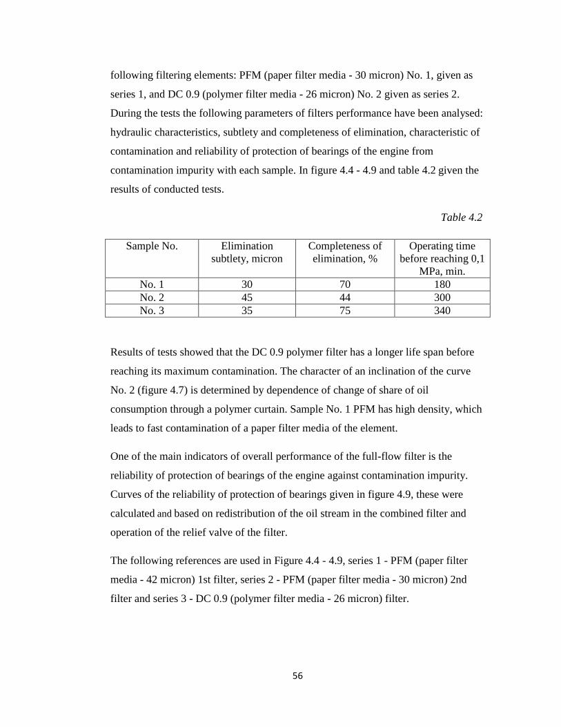
4.1.1. Research of polymer filter elements.
The present research relates to the polymer filter for filtration of engine oil and
polymer filter elements, these elements are of depth type, produced in form of
cylinders consisting of porous mass. Polymer elements made using mixture of
polyvinyl chloride (PVC), polyethylene terephthalate (PET) and compatibilising
agents which facilitates blending of PET and PVC. The porosity of filter elements
defined as correlation of total volume of pores of a sample to its total volume,

53
comprised 0,9 that exceeded the level of paper filtering materials shown in table 4.1.
. Table 4.1
Porosity of filtering materials
Filtering material Thickness, mm Porosity
DC 0.9 9,96 0,9
PFM - 1 0,87 0,82
PFM - 2 0,35 0,75
In figure 4.9 and 4.10 given following characteristics of polymer filter elements:
dependence of change of oil consumption and reliability of protection of bearings.
Polymer filters DC 0.9 shown in figure 4.3, were produced with following
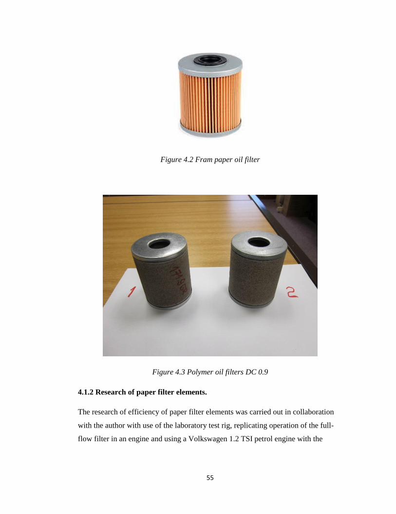
dimensions: Ø-80mm and H-100mm, these are identical to the original “Fram” oil
filter, shown in figure 4.2. Polymer elements have a slightly increased initial
resistance compared to paper elements and sufficient service life due to their
increased surface area (x5).

54
1- Micro-glass filter media 2 - Cellulose filter media
3 - Synthetic filter media 4 - Synthetic micro-glass media
5 - Polyester filter media 6 - Metal mesh filter media
Figure 4.1 Images of various filtering materials used in full-flow oil filters
55
Figure 4.2 Fram paper oil filter
Figure 4.3 Polymer oil filters DC 0.9
4.1.2 Research of paper filter elements.
The research of efficiency of paper filter elements was carried out in collaboration
with the author with use of the laboratory test rig, replicating operation of the full-
flow filter in an engine and using a Volkswagen 1.2 TSI petrol engine with the
56
following filtering elements: PFM (paper filter media - 30 micron) No. 1, given as
series 1, and DC 0.9 (polymer filter media - 26 micron) No. 2 given as series 2.
During the tests the following parameters of filters performance have been analysed:
hydraulic characteristics, subtlety and completeness of elimination, characteristic of
contamination and reliability of protection of bearings of the engine from
contamination impurity with each sample. In figure 4.4 - 4.9 and table 4.2 given the
results of conducted tests.
Table 4.2
Sample No. Elimination
subtlety, micron
Completeness of
elimination, %
Operating time
before reaching 0,1
MPa, min.
No. 1 30 70 180
No. 2 45 44 300
No. 3 35 75 340
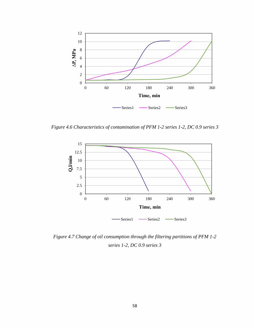
Results of tests showed that the DC 0.9 polymer filter has a longer life span before
reaching its maximum contamination. The character of an inclination of the curve
No. 2 (figure 4.7) is determined by dependence of change of share of oil
consumption through a polymer curtain. Sample No. 1 PFM has high density, which
leads to fast contamination of a paper filter media of the element.
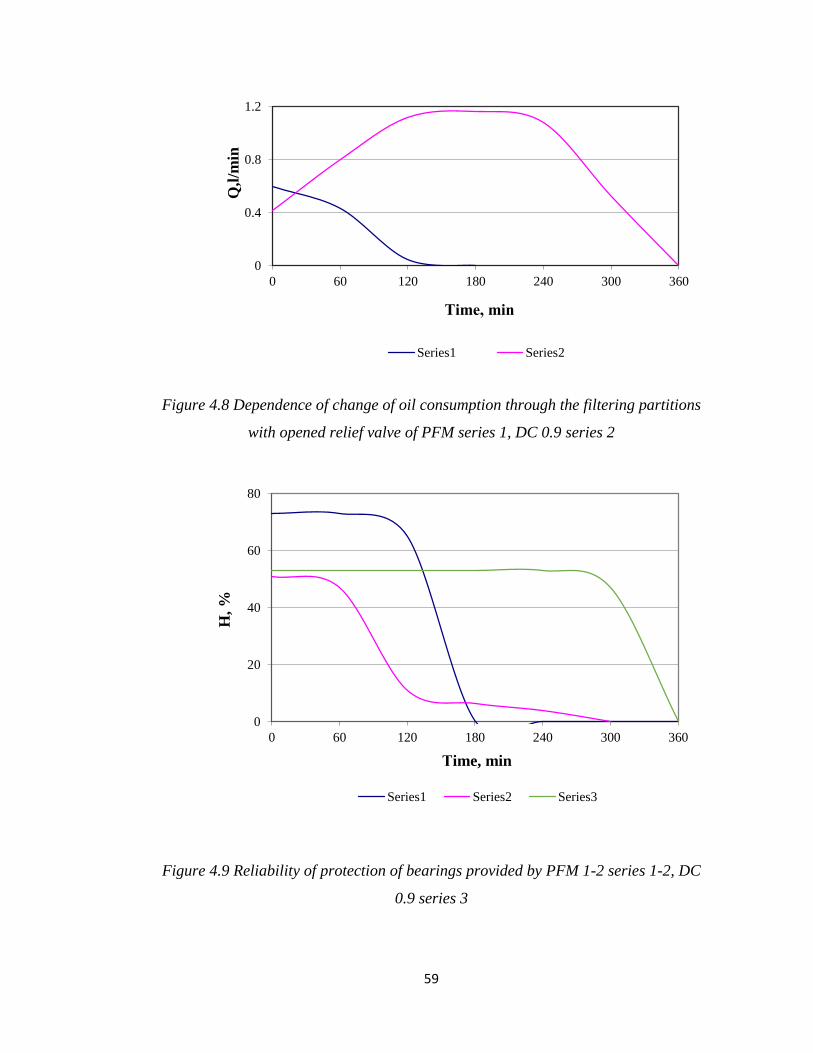
One of the main indicators of overall performance of the full-flow filter is the
reliability of protection of bearings of the engine against contamination impurity.
Curves of the reliability of protection of bearings given in figure 4.9, these were
calculated and based on redistribution of the oil stream in the combined filter and
operation of the relief valve of the filter.
The following references are used in Figure 4.4 - 4.9, series 1 - PFM (paper filter
media - 42 micron) 1st filter, series 2 - PFM (paper filter media - 30 micron) 2nd
filter and series 3 - DC 0.9 (polymer filter media - 26 micron) filter.

57
Figure 4.4 Hydraulic characteristics of PFM 1-2 series 1-2, DC 0.9 series 3
Figure 4.5 Hydraulic characteristics of relief valves of PFM 1-2 series 1-2, DC 0.9 series 3
0
1
2
3
0 5 10 15 20 25 30
∆P
, M
Pa
Q, l/min
Series1 Series2 Series3
0
0.02
0.04
0.06
0.08
0.1
0.12
0.14
0.16
0.18
0 10 20 30
∆P
, M
Pa
Q, l/min
Series1 Series2 Series3
58
Figure 4.6 Characteristics of contamination of PFM 1-2 series 1-2, DC 0.9 series 3
Figure 4.7 Change of oil consumption through the filtering partitions of PFM 1-2
series 1-2, DC 0.9 series 3
0
2
4
6
8
10
12
0 60 120 180 240 300 360
∆P
, M
Pa
Тime, min
Series1 Series2 Series3
0
2.5
5
7.5
10
12.5
15
0 60 120 180 240 300 360
Q,l
/min
Тime, min
Series1 Series2 Series3
59
Figure 4.8 Dependence of change of oil consumption through the filtering partitions
with opened relief valve of PFM series 1, DC 0.9 series 2
Figure 4.9 Reliability of protection of bearings provided by PFM 1-2 series 1-2, DC
0.9 series 3
0
0.4
0.8
1.2
0 60 120 180 240 300 360
Q,l
/min
Тime, min
Series1 Series2
0
20
40
60
80
0 60 120 180 240 300 360
H, %
Тime, min
Series1 Series2 Series3

60
4.2. Conclusions
1. Carried out research of volume polymer filter elements for full-flow oil filters,
demonstrated that these elements have the satisfactory subtlety of elimination (from
20 to 26 microns), required porosity (0,9) and sufficient contaminant holding
capacity, these elements have an increased initial hydraulic resistance which is still
within filters technical specification.
2. Carried out research established advantages of the application of the polymer
filtering media in full-flow oil filters for diesel and petrol engines. The polymer
filtering media used in the DC 0.9 oil filter has the nominal subtlety of elimination
of 20-26 microns.
3. The application of polymer filtering media instead of PFM (paper filtering media)
allows to increase the service life of polymer filtering elements by 3 times, at the
same time there is no adverse impact on reliability of the engine operation and
provide considerable economic effect through an extended lifespan of filtering
elements resulting in a decrease in the number of used oil filters. It should be noted
that engine oil possesses necessary stock of quality.

61
Chapter 5 – Theory
5. Calculation and analytical researches of oil filtration systems
5.1 Schemes of cleaning systems
In diesel engines the following cleaning systems are used:
- combined oil filtration system with the full-flow paper filter (FFF) and the by-pass
centrifuge (BPC), or the by-pass filter - BPF;
- combined oil filtration system with the by-pass centrifuge (BPC);
- combined oil filtration system with the by-pass centrifuge (BPC), included in
lubrication system of the engine before the full-flow filter;
- oil filtration system with the full-flow paper filter (FFF).
Tests were conducted on an engine test bench with the Cummins ISB e-4 diesel
engine using three cleaning systems:
FFF + BPC included in the filtration system before FFF;
FFF + BPF with inclusion in the filtration system after FFF;
FFF.
5.2 Researches of the efficiency of oil filtration and reliability of protection of
bearings of the engine against contamination impurity
The efficiency of oil filtration is determined by two following factors [56]:
- coefficient of elimination of the cleaner which characterizes the completeness of
the oil filtration from the contamination impurity for one pass of engine oil through
the cleaner. For particles of contamination of one size the coefficient of elimination
is called fractional;

62
- coefficient of elimination on oil consumption through the cleaner in a unit of time
Q, expressed as Q which characterizes intensity of filtration of contamination
impurity from the engine oil over a specific period of time.
The coefficient of elimination is presented as:
(5.1) 121 / XXX ,
where 1X and
2X - the content of contamination impurity before and after the
cleaner.
The total coefficient of elimination of the combined cleaning system (FFF + BPC
fed by oil to FFF) is determined as:
(5.2) ;ffffffbpcbpc mm
For the cleaning system of FFF + BPF with inclusion after FFF:
(5.3) ;1 fffbpfbpfffffff mm
For the cleaning system consisting of one FFF:
(5.4) ;fff
Total intensity of cleaning by combined system is determined by equation Q
where Q - total volume of oil consumption in a unit of time, moving from the pump
to the engine:
bpfbpcfff ,, - coefficients of elimination by the full-flow filter, the by-pass
centrifuge and the by-pass filter:

63
bpfbpcfff mmm ,, - shares of oil consumption through the full-flow filter, the by-
pass centrifuge and the by-pass filter from quantity of the oil, moving from the pump
to the engine.
Calculation of coefficient of elimination of the centrifuge was carried out by
equation:
(5.5)
Q
p
pe
rR
R 2122
9
1
2
0
2
2
1
where pR - radius of internal surface of the rotor;
r0 - internal radius of layer of liquid in the rotor;
- angular speed of rotation of the rotor;
- the working volume of the rotor ( 2
0
2 rRh p );
h - average height of the rotor);
- size (diameter) of particles of contamination;
21 и - density of particle and oil ( 21 );
Q - quantity of oil consumption through the centrifuge over a specific period
of time;
- dynamic viscosity of oil.
Carrying out calculations allows to determine the probability of passage of particles
of contamination to bearings пт and the reliability of their protection from
particles Npт by following ways (1,2):
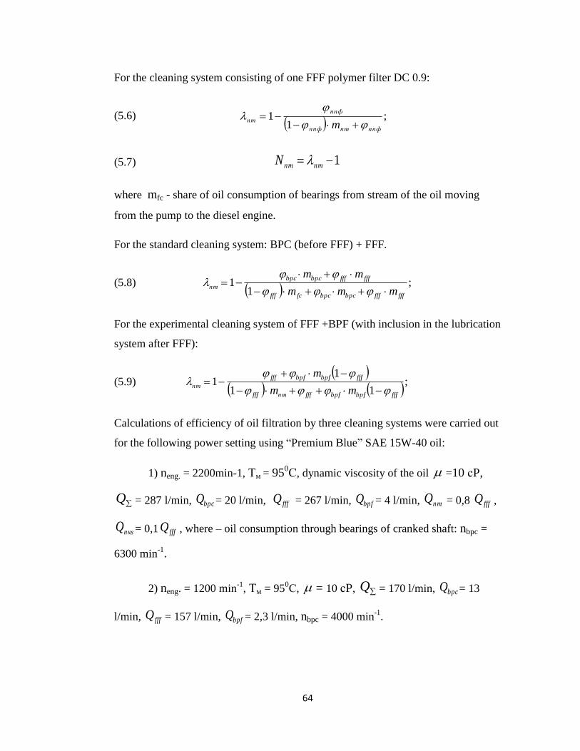
64
For the cleaning system consisting of one FFF polymer filter DC 0.9:
(5.6)
;1
1ппфптппф
ппф
птm
(5.7) 1 птптN
where mfc - share of oil consumption of bearings from stream of the oil moving
from the pump to the diesel engine.
For the standard cleaning system: BPC (before FFF) + FFF.
(5.8)
;1
1ffffffbpcbpcfcfff
ffffffbpcbpc
птmmm
mm
For the experimental cleaning system of FFF +BPF (with inclusion in the lubrication
system after FFF):
(5.9)
;
11
11
fffbpfbpffffптfff
fffbpfbpffff
птmm
m
Calculations of efficiency of oil filtration by three cleaning systems were carried out
for the following power setting using “Premium Blue” SAE 15W-40 oil:
1) neng. = 2200min-1, Тм = 950С, dynamic viscosity of the oil =10 сP,
Q = 287 l/min, bpcQ = 20 l/min, fffQ = 267 l/min, bpfQ = 4 l/min, птQ = 0,8 fffQ ,
пквQ = 0,1 fffQ , where – oil consumption through bearings of cranked shaft: nbpc =
6300 min-1.
2) neng. = 1200 min-1
, Тм = 950С, = 10 сP, Q = 170 l/min, bpcQ = 13
l/min, fffQ = 157 l/min, bpfQ = 2,3 l/min, nbpc = 4000 min-1
.

65
3) neng. = 1200 min-1
, Тм = 600С, = 31,2 сP, Q = 173 l/min, bpcQ = 16
l/min, bpfQ = 2,3 l/min, fffQ =157 l/min, nbpc = 4000 min-1
.
Coefficients of elimination of the centrifuge were determined in the following
modes, given in tab. 5.1.
. Table 5.1
Number of
operating
mode
Nen., мin-1
Тм, r0C
, сP
Nbpc,
мin-1
Рbpc,
kg/cm2
,bpcQ
l/min
1 2200 95 11 6200 8,2 19
2 1200 95 11 3900 3,4 12
3 1200 80 14 3900 4,1 12
4 1200 60 32,2 3900 5,9 15
5 1200 30 250 2300 10,2 19
Note. neng. Nbpc. - speed of rotation of cranked shaft of the engine and rotor
centrifuge; Тм, - temperature and dynamic viscosity of engine oil, Рbpc and bpcQ -
oil pressure before the centrifuge and engine oil consumption through the centrifuge.
In figure 5.1 given fractional coefficients of elimination of the by-pass centrifuge in
operating modes, according to data in table 5.1 for the full-flow paper filter and by-
pass filters 1 and 2.
Numbers of curves 1, 2, 3, 4, 5 correspond to numbers of operating modes of the
centrifuge given in table 5.1. Continuous lines of organic particles with density of
1 = 1,1 g/cm3, dotted 1’, 2’, 3’, 4’, 5’ - for quartz particles (
1 = 2,5 g/cm3) and a
stroke - dotted 1", 2", 3", 4", 5" - for iron particles (1 = 7,9 g/cm
3).
Fractional coefficients of elimination given in figure 5 by the full-flow filter under
numbers 6 and by-pass filters 1 and 2 under numbers of curves 7 and 8.
It is visible that fractional coefficients of elimination of particles provided by the
centrifuge significantly depend on the sizes and density of particles of contamination

66
speed and temperature setting of the engine operation, pressure and viscosity of the
engine oil and its consumption through the rotor. Fractional coefficients of
elimination by porous filters from insoluble in oil particles of contamination do not
depend on viscosity, temperature and the oil consumption. The coefficient of
elimination of centrifuges and filters is affected by the quantity of retained
contaminants at the same time the coefficient of elimination of centrifuges tend to
decrease and the coefficient of elimination of filters and by-pass filters increases.
However the oil consumption of filters considerably decreases as a result of intensity
of the oil filtration in the engine provided by filters and significantly more than by
centrifuges.
For the centrifuges the limit of its clearing ability (centrifugation) can be determined
and characterized by the critical size of particles, below this limit sedimentation of
particles in the rotor does not occur.
(5.10) ;7,2 42
pA
г
крRN
ТR
where Rg - universal gas constant;
T - absolute temperature of the oil, K;
NA - Avogadro's number (NA=6,022х1023
mol-1
);
- difference of density of the particle and the oil.
In figure 5.2 – 5.5 given data related to the intensity of oil filtration by three oil
filtration systems. It is visible that the essential difference in intensity of the oil
filtration by three systems takes place from particles of small sizes up to 5 microns.
Thus the oil filtration of organic particles is significantly better when the by-pass
filter is included in the combined system, and from quartz and iron particles – with
the inclusion of the by-pass centrifuge in the filtration system.

67
Figure 5.2 Dependence of intensity of oil filtration Q on size of impurity particles , RPM
= 2200, T = 950 C, PFM 1-2 series 1-2, DC 0.9 series 3
0
40
80
120
160
200
240
280
0 5 10 15 20 25 30 35 40 45 50 55 60
Qʮ
, l
/min
,
δ, µm
Series1 Series2 Series3

68
Figure 5.3 Dependence of intensity of oil filtration Q on size of impurity particles , RPM
= 2200, T = 950 C, PFM 1-2 series 1-2, DC 0.9 series 3
0
2
4
6
8
10
12
14
16
18
20
0 2 4 6 8 10
Q, l/
min
,
µm
Series1 Series2 Series3

69
Figure 5.4 Dependence of intensity of oil filtration Q on size of impurity particles , RPM
= 1200, T = 950 C, PFM 1-2 series 1-2, DC 0.9 series 3
0
1
2
3
4
5
6
7
8
9
10
0 2 4 6 8 10
Q, l/
min
,
µm
Series1 Series2 Series3

70
Figure 5.5 Dependences of intensity of oil filtration Q on size of impurity particles ,
RPM = 1200, T = 600 C, PFM 1-2 series 1-2, DC 0.9 series 3
0
1
2
3
4
5
6
7
8
9
10
0 2 4 6 8 10
Q, l/
min
,
µm
Series1 Series2 Series3

71
With a decrease in the engine speed power setting and a reduction of the oil
temperature in the oil sump, the intensity of the oil filtration Q when using BPC
significantly decreases than when using BPF which is connected with pressure and
viscosity of the oil that in turn effects more operation of the centrifuge, than the
filter.
Considering that essential mass of particles of natural contamination of oil has the
average sizes 1-3 microns and in the most part is organic, general oil filtration of
essential mass of particles when using BPF is better than when using BPC and as a
result of that permissible concentration of contamination impurity in the oil and
level of its ageing when using BPF is less. However the high intensity of the oil
filtration of BPC from inorganic particles, especially large particles 3-9 microns in
size, should have a positive impact on reduction of the wear of moving parts of the
engine.
It is confirmed by less probability "" cb of presence of such inorganic particles in
bearings, in particular in bearings of cranked shaft, and considerably improved
reliability of protection of “Ncf” of bearings against such particles when using BPC,
than BPF and especially, than only FFF (figure 5.6 - 5.9). Therefore by using BPC
the probability of presence of particles in bearings and reliability of their protection
significantly depends on speed and temperature (oil) modes of the engine operation.
5.3 Conclusions
1. The efficiency of the oil filtration using the following three filtration systems:
full-flow (paper filter media) and combined (paper and polymer filter media),
including the full-flow paper oil filter and the by-pass centrifuge in combination
with the by-pass oil filter tested at various speed and temperature power setting is
investigated and defined.
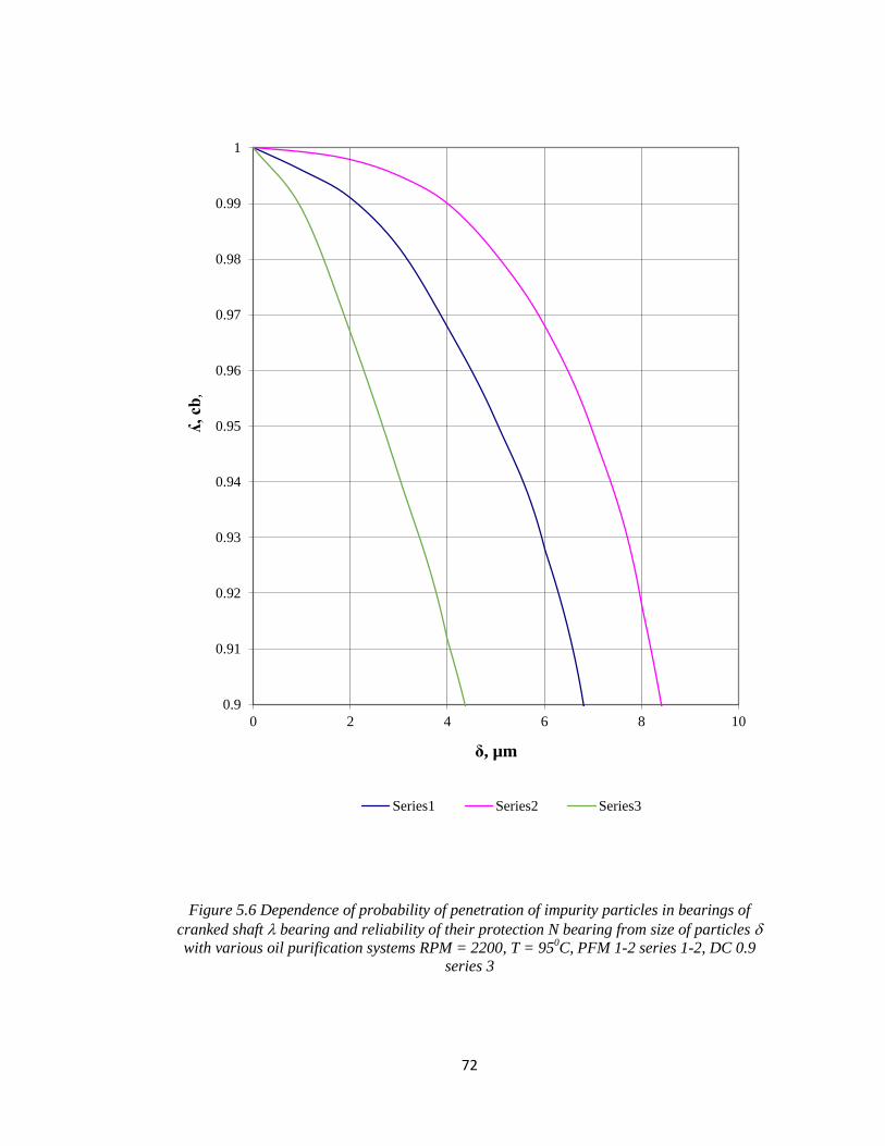
72
Figure 5.6 Dependence of probability of penetration of impurity particles in bearings of
cranked shaft bearing and reliability of their protection N bearing from size of particles
with various oil purification systems RPM = 2200, T = 950C, PFM 1-2 series 1-2, DC 0.9
series 3
0.9
0.91
0.92
0.93
0.94
0.95
0.96
0.97
0.98
0.99
1
0 2 4 6 8 10
ʎ, cb
,
δ, µm
Series1 Series2 Series3

73
Figure 5.7 Dependence of probability of penetration of impurity particles in bearings of
cranked shaft bearings and reliability of their protection N bearings from size of particles
with various oil filtration systems RPM = 2200, T = 600C, PFM 1-2 series 1-2, DC 0.9
series 3
0.52
0.56
0.6
0.64
0.68
0.72
0.76
0.8
0.84
0.88
0.92
0.96
0 2 4 6 8 10
ʎ, cb
δ, µm
Series1 Series2 Series3

74
Figure 5.8 Dependence of probability of penetration of impurity particles in bearings of
cranked shaft bearings and reliability of protection N bearings from size of particles
with various oil filtration systems RPM = 1200, T = 950C, PFM 1-2 series 1-2, DC 0.9
series 3
0.52
0.56
0.6
0.64
0.68
0.72
0.76
0.8
0.84
0.88
0.92
0.96
0 2 4 6 8 10
ʎ, cb
δ, µm
Series1 Series2 Series3

75
Figure 5.9 Dependence of probability of penetration of impurity particles in bearings of
cranked shaft bearings and reliability of protection N bearings from size of particles
with various oil filtration systems RPM = 1200, T = 600C, PFM 1-2 series 1-2, DC 0.9
series 3
0.52
0.56
0.6
0.64
0.68
0.72
0.76
0.8
0.84
0.88
0.92
0.96
0 2 4 6 8 10
ʎ, cb
,
δ, µm
Series1 Series2 Series3

76
2. Fractional coefficients of elimination of impurity particles have an impact on
impurity of the by-pass filter and the centrifuge, which in case with oil filters do not
depend on viscosity and oil consumption, are defined. At the same time the
coefficient of elimination of the centrifuge, gradually decreases, and the coefficient
of elimination of by-pass filters, in the process of contamination increases, however
there is a decrease in the intensity of filtration through a decrease in oil consumption
through the filter.
3. The essential difference in the intensity of oil filtration with three filtration
systems, takes place for particles of small sizes up to 5 microns, at the same time oil
filtration of organic particles of contamination is significantly improved with an
addition of the by-pass filter to the combined system, and from inorganic particles
with an addition of the by-pass centrifuge.
Chapter 6 – Discussion
6. Research and development of combined oil filtration systems
The carried-out review and analysis of technical literature related to combined oil
filtration systems with replaceable by-pass filters and analysis of samples of filters
showed that 5 main variants of designs of filter elements found broad application
(figure 1.28).
When choosing initial polymer materials for filtering elements, relevant
requirements for filter elements related to resistance, subtleties of elimination,
mechanical durability, oil, acid and water resistance, availability and cost of
polymers were considered.
Taking into account the specified requirements the following types of polymers were
chosen: polyvinylchloride (PVC) and polyethylene terephthalate (PET), a mixture of
both polymers was used to produce filtering materials.
Physical and chemical properties of filtering materials given in table 6.1.

77
Table 6.1
Physical and chemical properties of filtering materials
Name of indicators Cellulose PVC/PET
Density, g/cm3 1,50 1,70
Destruction temperature, 0С 180 200
Flash temperature, 0С 250 -
Ignition temperature, 0С 450 -
Durability, gs/tex 15-17 30
Moisture absorption at 200С
and 70% of humidity, %
10 100
For the definition of an optimum polymer composition samples of filtering materials
were made of the following polymers:
- PVC - 10%;
- PET - 80%.
The % choice of a polymer composition is based on results of preliminary
experiments and previously conducted in collaboration with the author researches on
filtering and contaminant retaining capacities and optimum values of mechanical
durability of polymer filtering materials and filter elements. It was found that a
polymer composition has a desirable feature to retain 100% of water in its porous
mass and its moisture absorption greater than paper filter medium by 90%.
Polymer filtering materials were prepared by the author at the laboratory of the
University of Sheffield in accordance with an appropriate technical specification
related to a polymer composition and a chemical formulation, design of polymer
filtering elements and the process of making filter elements.
Characteristics of filtering materials presented in table 6.2 based on selected
compositions of two polymers.

78
Table 6.2
Characteristics of filtering materials
Material of
filtering elements Р
mmHg
Т
mm
М
kg
Note
PFM paper 81 0,80,2 0,100,02 Cellulose fibers 12-15
micron thick;
PVC and PET 100,1 100,1 0,50,03 PVC and PET granules
70-500 microns
where Р - resistance to air stream/specific speed of 0,2 l/min of cm2;
T - thickness of material, mm, М – weight of 1 m2 of material.
For comparison purposes the PFM (paper filter media) was used in laboratory tests.
As shown in table 6.3 the use of a polymer filter media causes an increase in
resistance of materials whereas thickness and mass of filtering materials with PVC
and PET types of polymers and granules diameters remain almost identical. This
results from the fact that in the small thickness of polymer material (100,1) mm
having porous mass structure, the specified indicators depend on diameters of
granules.
Preparation of polymer filtering material and filter elements is provided as described
below:
The apparatus comprises a chute into which a mixture comprising a plastics material
is fed. The electrically powered screw conveyor moves the mixture into a mould via
a receiver which acts as a funnel to direct the mixture to the mould. Once the
mixture in a mould has been compressed, the indexing pin is withdrawn to permit
rotation of the turntable platter, moving an empty mould into the mixture-receiving
position and moving the mould containing the filter element precursor body into an
unloading position. The operation of the apparatus is controlled by control panel.
Once the mixture has been delivered to the mould via the receiver, the mixture is
compressed. The electrically-operated piston engages with the tamping member and

79
urges the tamping head into compressive contact with the material in the mould. A
mixture comprising a plastics material is formed by mixing 10% by weight of
granules of polyvinyl chloride (PVC), 80% by weight of granules of polyethylene
terephthalate (PET), 8-9% by weight of a compatibilising agent and 0,02-2% by
weight of a liquid. The compatibilising compound facilitates the blending together
of PVC and PET. The produced filter element is suitable for laboratory and bench
tests.
6.1. Laboratory and bench tests of by-pass filters
To carry out bench tests the standard filter housing was used, which enabled to test
filtering elements with the following dimensions: Ø 80 and 100 mm high.
Tests of filters were carried out using the Premium Blue SAE 15W-40 oil at
temperature of 900С. During tests of filters the following characteristics were
defined: hydraulic subtlety of elimination and the contaminant capacity of a filtering
element.
The lifespan of filter elements before reaching its end was determined by recorded
reduction of oil consumption through the filter elements by 60%, through
contamination by quartz dust with the specific surface of 10500 cm2/g.
Tests of filters were carried out with application of mathematical methods of
planning of experiment according to the plan of DFE 24-1
(fractional factorial
experiment at two levels) for obtaining incomplete square model taking into account
interaction. In tests the following model was used:
У = в0 + в1Х1 + в2Х2 + в3Х3 + в4Х4 + в12Х12 + в13Х13 + в14Х14 +
в23Х23 + в24Х24 + в34Х34;
considering mutual influence of factors.
Researched factors and levels of their variation given in table 6.3

80
Table 6.3
Researched factors and levels of filter elements variation
No. Factors Code
value
Variation levels
-1 0 +1
1 Structure of filtering element
(diameter of granules +
composition content of CC, %)
Х1
0
10
20
2 Density of filtering element
(mass), g
Х2 250
(500)
275
(550)
300
(600)
3 Agglomeration temperature, 0С Х3 140 160 180
4 Time of agglomeration, min Х4 50 70 90
Plan of carrying out DFE 24-1
No.
experim.
Factors Criterion functions
Structure Weight
F.E.
Agglomeration
t0
Set time
У1
У2
У3
У4
Х1 % CC Х2 gram. Х3 0С Х4 min
1 + + + +
2 + + - -
3 + - + -
4 + - - +
5 - + + -
6 - + - +
7 - - + +
8 - - - -
9 0 0 0 0
10 0 0 0 0
11 0 0 0 0
Criterion functions of bench tests:
У1 - the hydraulic characteristic of filter;
У2 - subtlety and completeness of elimination of filtering element;
У3 - contaminant capacity of filtering element;
У1 - water resistance.
81
Results of conducted by the author experiments are analysed and on their basis the
dependences of influence of the structure of filtering elements, their weight,
temperature and time of agglomeration for criterion functions are investigated.
The most significant interest presents the analysis of dependences У1 = f (X1,X2)
and У2 = f (Х1,Х2), determining the hydraulic resistance and the contaminant
capacity of filtering elements.
Dependence У1 = f (X1,X2) presented as:
У1 = 0,396 + 0,139 Х1 – 0,031 Х2 + 0,026 Х12;
factors Х3 and Х4 have zero values.
Dependence У2 = f (Х1,Х2) presented as:
У2 = 144,75 - 59,5 Х1 + 11,0 Х2 - 4,25 Х12;
factors Х3 and Х3 have zero values.
In the obtained equation of value of factors, which are presented in the coded form.
Transition to the equation of function response surface in natural values of
researched factors is carried out by substitution of values:
i
ioi ХХХ
where Хi - value of “i" factor;
Хio - value of “i” factor at zero level;
i - interval of variation of “i” factor;
In figure 6.1 given image of function response surface.

82
У1 = f (X1,X2) (shaded plane ABCD) in the coded values of coordinates of X1 and
X2. In figure 6.2 is given image of function surface.
У2 = f (X1,X2) (plane ABCD). It is visible that use in filtering elements of polymer
granules (CC) considerably increases the hydraulic resistance of elements.
In figure 6.3 given image of function response surface У3 = f (X3,X4), defining
operating time of the filter before contamination, depending on time and temperature
of agglomeration of filtering elements. It is noticeable that these factors do not
influence filter operating time before contamination.
Porosity of filtering elements (m) was determined as a correlation of total volume of
pores of sample (Vn) to its total volume (V0):
0V
Vm n or
t
m
01
where 0 - density of sample;
t - density of firm part of sample.
The porosity of filtering elements No: 1 determined thus (containing 20% of CC)
and No. 2 (not containing CC), comprised 86 and 88% respectively and matches the
level of paper filtering materials.
Thus there is some decrease in oil consumption with its subsequent stabilization. For
the filter element from (PVC + PET) (10х80%) there is a decrease in oil
consumption by 15% as a result of polymer material ability to absorb water, for the
filter element from viscose (100%) by 5%.

83
Y1 Hydraulic resistance, MPa
B
A
20
D C
10
0
X2 Content of UTB, %
300 275 250
Weight of filtering elements, g
Figure 6.1 Surface of response (ADCD) function Y1=f(X1,X2) depending on content of UTV
and weight of filtering elements, factors X3, X4 have zero values
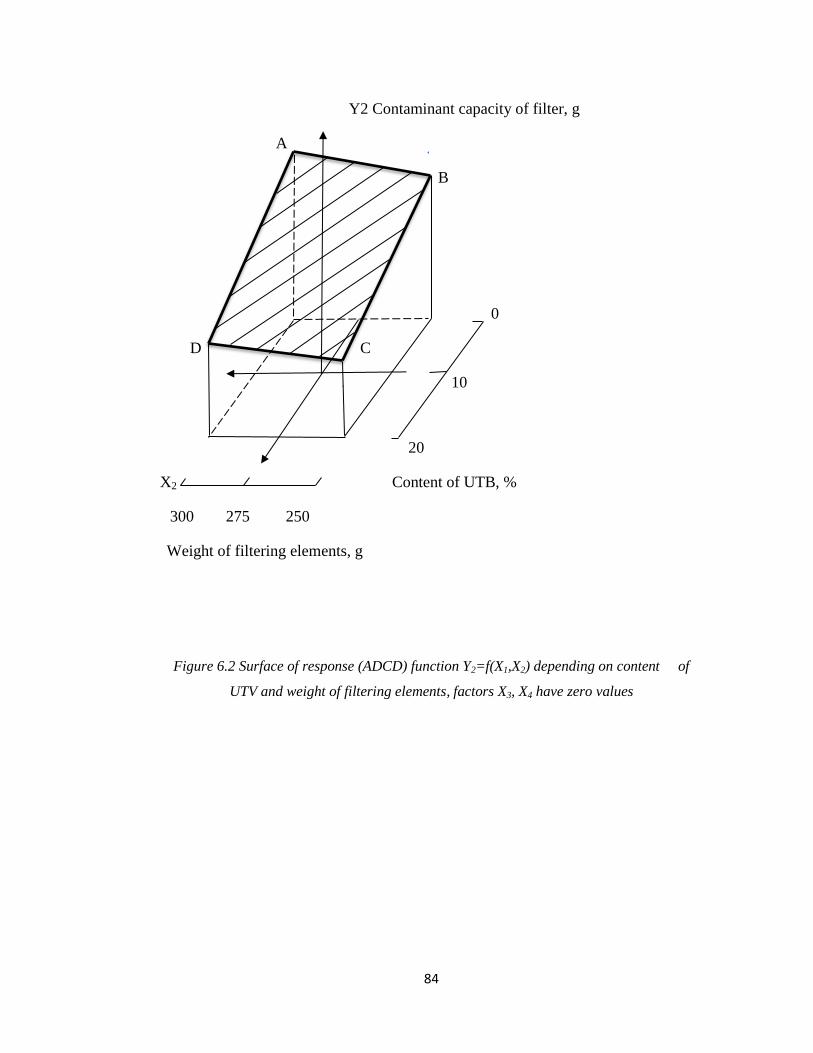
84
Y2 Contaminant capacity of filter, g
A
B
0
D C
10
20
X2 Content of UTB, %
300 275 250
Weight of filtering elements, g
Figure 6.2 Surface of response (ADCD) function Y2=f(X1,X2) depending on content of
UTV and weight of filtering elements, factors X3, X4 have zero values

85
Y3 Time of filter operation, hrs
A B
X
200
D C
180
X4
X3 160
Temperature of agglomeration
30 50 70 of filtering element °C, (X3)
Time of agglomeration, min (X4)
Figure 6.3 Surface of response (ADCD) function Y3=f(X3,X4) depending on temperature of
smelting and length of smelting of filtering element, factors X1, X2 have zero values

86
Tests of filtering elements for the thermal stability were carried out as per following
procedure: filtering elements were placed in the container with the oil before their
full immersion. Then the container consistently cooled in the fridge and later heated
up in the oven and cooled down at the room temperature in the following cycle:
- keeping at temperature – 500C - 65;
- keeping at temperature + 1400C - 65;
- keeping at temperature + 300C - 125.
On completion of laboratory tests the visual assessment of filter elements and
determination of their hydraulic characteristics was carried out. There was not a
significant change in oil consumption through filtering elements before and after
tests, which did not exceed more than 5%.
6.2 Engine bench tests of combined oil filtration systems
Tests were carried out in collaboration with the author on the engine bench using the
Cummins ISB e-4 diesel engine connected to hydraulic brake (dynamometer)
Schenk D 700-IE. This engine installation included connection of the air flow to the
suction of turbocharger and exhaust gas output (turbine of the filling aggregate) into
the discharge manifold of exhaust gases, fuel supply and cooling air supply to the
engine. Other installed equipment included: flow meter of crankcase gases; device
for sampling of the exhaust gases for the analysis of their smoke, manometers for
measurement of pressure drop across oil filters, a flow meter for measurement of oil
consumption via the by-pass filter, a device for supplying of part of the exhaust
gases in the crankcase with measurement of its temperature and quantity. For all
tests of the engine Cummins ISB e-4, standard diesel fuel was used with
specification EN 590:2004.
The image of the engine bench with an installed Cummins engine shown in Figure
6.4.

87
Technical specification of the engine Cummins ISB e-4 used for laboratory tests of
combined oil filtration systems is described below:
Basic data of the engine Cummins ISB e-4
Diesel engine: Cummins ISB e-4, water cooling
Bore: 107.6 mm
Stroke: 123.7 mm
Cylinder number, arrangement: 4 - stroke
Displacement volume 4,499 1
Compression ratio ɛ: 17.5
Rated power of engine: 130Kw/2300 rpm
Torque of engine max. Mt-ISO: 680 Nm/1500 rpm
Injection set: Common Rail, Bosch B 445 224 151
Injectors: Bosch 23 30 957
Pressure opening: 40 - 180 MPa
Intercooler: Cummins No: 345 228 241
Turbocharger: Holset – type HE 22 1M/H050112120
6.2.1 Engine tests of Cummins ICB e-4 diesel engine
Tests were carried out in cycles in following modes shown in table 6.4.
Table 6.4
Stage of
tests
Rotation
frequency,
min.-1
Loading,
kg. m
Temperature
of water/oil, 0С
Length of
operation,
min.
Consumption
of crankcase
gases, l/min
"cold" 1200 15 26/30 140 105-110
"hot" 2200 60 90/110 260 115-120

88
Figure 6.4 Engine test bench Cummins ISB e-4
6.2.1.1 Physical and chemical properties of engine oil
During the tests of oil filters samples of the oil were taken from the crankcase of the
Cummins ICB e-4 diesel engine for laboratory analysis of oil samples, carried out in
accordance with ASTM standards.
Samples of the oil were taken by a technician every 20 hours at equal intervals:
20hrs, 40hrs, 60hrs, 80hrs, 100hrs, 120hrs and on completion of tests of three fuel
filtration systems tested, 2 paper and 1 polymer oil filters were removed by a
technician for further laboratory analysis of oil filters and also analysis of retained
by filter media (paper and polymer) contaminants.
On completion of the bench engine tests a technician also removed moving parts
from the engine for the laboratory analysis in relation to wear tests of parts.
In figure 6.5-6.9 shown results of the analysis of tested oil samples.
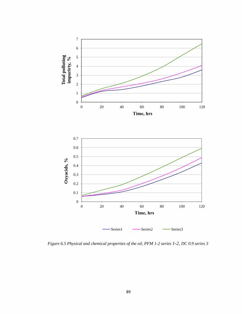
89
Figure 6.5 Physical and chemical properties of the oil, PFM 1-2 series 1-2, DC 0.9 series 3
0
1
2
3
4
5
6
7
0 20 40 60 80 100 120
To
tal
po
llu
tin
g
imp
uri
rty,
%
Тime, hrs
0
0.1
0.2
0.3
0.4
0.5
0.6
0.7
0 20 40 60 80 100 120
Oxyaci
ds,
%
Тime, hrs
Series1 Series2 Series3

90
Figure 6.6 Physical and chemical properties of the oil, PFM 1-2 series 1-2, DC 0.9 series 3
0
10
20
30
40
50
60
70
0 20 40 60 80 100 120
Asp
halt
enes
, %
Тime, hrs
0
0.5
1
1.5
2
2.5
3
3.5
0 20 40 60 80 100 120Karb
ena,
karb
oid
a u
nb
urn
ab
le, %
Тime, hrs
Series1 Series2 Series3

91
Figure 6.7 Physical and chemical properties of the oil, PFM 1-2 series 1-2, DC 0.9 series 3
0
0.1
0.2
0.3
0 20 40 60 80 100 120
Un
bu
rnab
le, %
Тime, hrs
0
0.5
1
1.5
2
2.5
3
0 20 40 60 80 100 120
Karb
ena a
nd
karb
oid
a, %
Тime, hrs
Series1 Series2 Series3

92
Figure 6.8 Physical and chemical properties of the oil, PFM 1-2 series 1-2, DC 0.9 series 3
0
20
40
60
80
0 20 40 60 80 100 120
Vis
cosi
ty A
PI
Тime, hrs
0
0.5
1
1.5
2
2.5
3
3.5
4
0 20 40 60 80 100 120
Alk
ali
nit
y, m
g K
OH
/g
Тime, hrs
Series1 Series2 Series3

93
Figure 6.9 Physical and chemical properties of the oil, PFM 1-2 series 1-2, DC 0.9 series 3
0
5
10
15
20
25
30
35
40
45
0 20 40 60 80 100 120
Aci
dit
y, m
g K
OH
/g
Тime, hrs
0
5
10
15
20
25
30
35
40
0 20 40 60 80 100 120
Ash
es s
ulf
on
ate
d, %
Тime, hrs
Series1 Series2 Series3

94
The use in the engine of the additional centrifuge along with the full-flow filter
reduced the content of total contamination impurity and maximum concentration of
total contamination impurity in the Premium Blue SAE 15W-40 oil of the Cummins
ICB e-4 diesel engine equipped with the additional by-pass filter and the centrifuge
did not exceed 4,5% (figure 6.5). Tests with the use of the only full-flow filter in the
engine showed content of total contamination impurity reached 5,5%, significantly
more than provided by the combined system. An increase in concentration of
contamination impurity in the oil with regular and polymer systems with by-pass
filters incurred evenly.
The content of oxyacids in the oil is significant when using only FFF and reaches
0,7%. When using FFF+CF reached 0,4%, and using FFF+BPF reached 0,55%.
The content of asphaltenes when using only FFF reached 3,5%, when using FFF+CF
reached 3,3%, and FFF+BFF reached 2,8%.
The content of carbenes, carboides and incombustibles when using only FFF reaches
3,8%, when using FFF+CF reached 1,3%, and FFF+PBPF reached 0,9%.
The content of unburnables in the oil when using only FFF reached 0,5%, when
using FFF+CF, and FFF+BPF is almost identical and reached 0,3%.
The content of carbenes and carboides, which structure is determined by the content
of soot, when using only FFF reached 4,5%, when using FFF+CF reached 0,9%.
The viscosity of the oil with an increase in the length of tests considerably increased
with FFF after 80 hours of tests reached 11,5 API. With increased length of tests
incurred an intensive increase in the viscosity of the oil. When using FFF+CF and
FFF+BPF for 120 hours of tests, the viscosity of the oil increased to 10,6 API and
10,5 API respectively.
The alkalinity of the oil during tests decreased and on completion of tests when
using only FFF reached 0,5 mg KOH/g, and when using FFF+CF and FFF+BPF 1,3-

95
1,4 mg KOH/g. respectively. The acidity of the oil with an increase in the length of
tests continuously increased and when using only FFF reached after 120 hours 2,5
mg KOH/g, when using FFF+CF and FFF+BPF - 2,1 and 1,5 mg KOH/g.
respectively. The content of sulphatic ashes when using only FFF reached 0,9%
when using FFF+CF and FFF+BPF - 0,68 and 0,77% respectively.
6.2.1.2 Quantity of deposits retained by filters and their component structure
In table 6.5 shown the quantity of deposits retained by filters of tested oil filtration
systems on completion of tests. It is visible that the largest quantity of deposits is
held by the centrifuge (CF) and the by-pass filter (BPF), while the dry phase of total
contamination impurity in CF comprised about 50%, in BPF 25%, in the full-flow
filter (FFF) 20%.
Table 6.5
Quantity of deposits retained by filters and centrifuges during tests of the engine
with various cleaning systems
Parameters
1 stage 2 stage 3 stage
Regular system Polymer system
(FFF+BPF)
Cleaning system
with FFF only
FFF CF+BP
F
FFF BPF FFF
1. Quantity of retained
deposits G, g
0,156
0,296
0,171
0,512
0,131
Х0, % (dry phase) 19,4 54,4 17,9 27,3 22,8
2. Component structure
of deposits, g
total content of insoluble
impurity
0,031
0,162
0,032
0,142
0,058
oxyacids 0,0034 0,071 0,0036 0,0092 0,0043
asphaltenes 0,0029 0.0049 0,0031 0,0031 0,0051
carbenes, carboides and
unburnables
0,250
0,150
0,025
0,103
0,049

96
6.2.1.3 Efficiency of operation of oil filters
For the assessment of efficiency of operation of oil filters and filtration systems were
defined:
- balance of contamination impurity found in the oil and retained by filters,
both total contamination impurity and their components;
- coefficient of oil filtration by filters and cleaning systems from total
contamination impurity and their components;
- service life of filter elements of full-flow filters and service life of the oil;
- impurity of piston group (various deposits);
- wear of moving parts of the engine.
The balance of total contamination impurity and their components found in the oil
and retained by filters during tests shown in table 6.6-6.11 and the coefficient value
of coefficient of oil filtration of various filters and systems shown in table 6.12.
The quantity of contamination impurity (total and their components entered engine
oil and retained by filters) is determined by the equation:
g1=gм+gyr+gп+g 3
The coefficient of oil filtration provided by the filter during tests is determined as:
1
3
g
gК i
i
where g3i - quantity of retained contamination impurity by an i - cleaner during tests.
The coefficient of the oil filtration system of filters is expressed as following:
1
3
g
gК
where g 3 - quantity of the contamination impurity retained by filters during tests.

97
Table 6.6
Balance of total contamination impurity in engines using various oil filtration
systems
No.
Designation and
parameter unit of
measure
1 stage 2 stage 3 stage
Regular system
Polymer system
(BPF instead of
CF-BPF)
Cleaning system
without BPF and
CF-BPF
FFF CF-BPF FFF BPF FFF
1 Х0, % 2,61 2,61 2,61
2 Хк, % 4,6 4,3 5,3
3 Хср, % 5,3 3,21 3,9
4 Gм, kg 20 20 20
5 gм, kg 0,439 0,377 0,586
6 Gуg, kg 13,14 16,27 12,33
7 gуg, kg 0,103 0,12 0,16
8 Gp, kg 1,49 1,49 1,31
9 Gp, kg 0,011 0,098 0,107
10 Gf, dry kg 0,64 - 0,644 0,407 0,644
11 Gf, mixed in oil 1,33 - 1,362 1,766 1,354
12 Gfз, after tests 1,496 - 1,549 2,279 1,583
13 Gз, (contaminated) 0,156 0,296 0,171 0,512 0,256
14 Х3, % 20,3 54,4 17.9 27,4 22.9
15 g3, kg 0,031 0,161 0,03 0,14 0,06
16 g3 , kg 0,193 0,071 0,058
17 g1, kg 0,751 0,669 0,834
18 g1, g/hour 5,95 5,31 7,58
19 Кi, % 4,25 21,4 4,58 21,1 7,02
20 К , % 25,75 25,5 7,02

98
Parameters given in tables:
Х0 and Хк - concentration of contamination impurity in engine oil before and after
tests;
Gм, Gуg, Gп - the weight of the oil being in crankcase, burned and taken during tests;
gуg - quantity of the contamination impurity found in engine oil during tests;
gуg - quantity of contamination impurity in burned-down engine oil;
gp - quantity of contamination impurity in samples of engine oil;
Хср - average concentration of contamination impurity in engine oil during tests;
Х3 - concentration of dry phase of contamination impurity;
G3 - quantity of products of contamination retained by filters and centrifuges during
tests;
g3, g3
- quantity of contamination impurity (dry phase) retained by each cleaner; all
cleaners together;
g1 - total quantity of contamination impurity entered engine oil of the engine during
tests:
g1=gм+gyr+gп+g 3

99
Table 6.7
Balance of oxyacids in Cummins ISB e-4 engine with various oil filtration systems
No
Designation and
parameter unit of
measure
1 stage 2 stage 3 stage
Regular system Polymer system
(BPF instead of
CF-BPF)
Cleaning system
without BPF and
CF-BPF FFF CF-BPF FFF BPF FFF
1 Х0, % 0,11 0,11 0,11
2 Хк, % 0,32 0,51 0,53
3 Хср, % 0,21 0,27 0,43
4 Gм, kg 20,9 20,9 20,9
5 gм, kg 0,041 0,083 0,091
6 Gуg, kg 13,14 16,27 12,33
7 gуg, kg 0,028 0,045 0,053
8 Gp, kg 1,49 1,49 1,31
9 Gp, kg 0,002 0,003 0,05
10 Gf, dry kg 0,64 - 0,694 0,407 0,644
11 Gf, mixed in oil 1,33 - 1,378 1,766 1,354
12 Gfз, after tests 1,49 - 1,551 2,281 1,583
13 Gз, (contaminated) 0,156 0,296 0,171 0,512 0,256
14 Х3, % 2,23 2,42 2,12 1,79 1,71
15 g3, kg 0,0034 0,0071 0,0035 0,0092 0,0043
16 g3 , kg 0,0106 0,0126 0,0043
17 g1, kg 0,0848 0,1468 0,1565
18 g1, g/hour 0,673 1,165 1,423
19 Кi, % 4,11 8,44 2,44 6,18 2,82
20 К , % 12,5 8,63 2,82

100
Table 6.8
Balance of asphaltenes in Cummins ISB e-4 engine with various oil filtration
systems
No.
Designation and
parameter unit of
measure
1 stage 2 stage 3 stage
Regular system
Polymer system
(BPF instead of
CF-BPF)
Cleaning system
without BPF and
CF-BPF
FFF CF-BPF FFF BPF FFF
1 Х0, % 2,25 2,21 2,2
2 Хк, % 2,98 2,91 3,1
3 Хср, % 2,5 2,4 2,6
4 Gм, kg 0,213 20 20
5 gм, kg 0,154 0,146 0,188
6 Gуg, kg 13,14 16,27 12,33
7 gуg, kg 0,323 0,406 0,332
8 Gp, kg 1,51 1,51 1,31
9 Gp, kg 0,038 0,037 0,035
10 Gf, dry kg 0,64 - 0,644 0,407 0,644
11 Gf, mixed in oil 1,33 - 1,362 1,766 1,354
12 Gfз, after tests 1,54 - 1,549 2,281 1,583
13 Gз, (contaminated) 0,156 0,298 0,171 0,512 0,256
14 Х3, % 2,17 1,75 1,51 5,37 1,79
15 g3, kg 0,002 0,004 0,002 0,002 0,004
16 g3 , kg 0,007 0,005 0,004
17 g1, kg 0,544 0,596 0,562
18 g1, g/hour 4,32 4,73 5,12
19 Кi, % 0,061 0,953 0,435 4,68 0,81
20 К , % 1,03 5,12 0,81

101
Table 6.9
Balance of deposit from carbenes and carboides in Cummins ISB e-4 engine with
various oil filtration systems
No.
Designation and
parameter unit of
measure
1 stage 2 stage 3 stage
Regular system
Polymer system
(BPF instead of
CF-BPF)
Cleaning system
without BPF and
CF-BPF
FFF CF-BPF FFF BPF FFF
1 Х0, % 0,24 0,14 0,24
2 Хк, % 1,02 0,81 2,3
3 Хср, % 0,3 0,2 1,12
4 Gм, kg 20 20 20
5 gм, kg 0,157 0,1364 0,451
6 Gуg, kg 13,14 16,27 12,33
7 gуg, kg 0,052 0,039 0,135
8 Gp, kg 1,49 1,49 1,31
9 Gp, kg 0,005 0,004 0,014
10 Gf, dry kg 0,64 - 0,644 0,407 0,644
11 Gf, mixed in oil 1,33 - 1,362 1,766 1,354
12 Gfз, after tests 1,49 - 1,551 2,281 1,583
13 Gз, (contaminated) 0,156 0,298 0,171 0,512 0,256
14 Х3, % 13,12 33,28 11,7 18,04 17,1
15 g3, kg 0,02 0,098 0,0202 0,092 0,0436
16 g3 , kg 0,1194 0,1128 0,0436
17 g1, kg 0,335 0,293 0,645
18 g1, g/hour 2,6 2,2 5,8
19 Кi, % 6,92 29,43 6,92 31,51 6,76
20 К , % 35,56 38,42 6,76
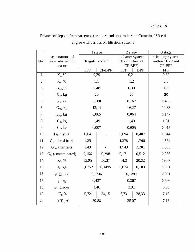
102
Table 6.10
Balance of deposit from carbenes, carboides and unburnables in Cummins ISB e-4
engine with various oil filtration systems
No:
Designation and
parameter unit of
measure
1 stage 2 stage 3 stage
Regular system
Polymer system
(BPF instead of
CF-BPF)
Cleaning system
without BPF and
CF-BPF
FFF CF-BPF FFF BPF FFF
1 Х0, % 0,29 0,21 0,32
2 Хк, % 1,1 1,2 2,5
3 Хср, % 0,48 0,39 1,3
4 Gм, kg 20 20 20
5 gм, kg 0,188 0,167 0,482
6 Gуg, kg 13,14 16,27 12,33
7 gуg, kg 0,065 0,064 0,147
8 Gp, kg 1,49 1,49 1,31
9 Gp, kg 0,007 0,005 0,015
10 Gf, dry kg 0,64 - 0,694 0,407 0,644
11 Gf, mixed in oil 1,35 - 1,378 1,766 1,354
12 Gfз, after tests 1,49 - 1,549 2,281 1,583
13 Gз, (contaminated) 0,156 0,298 0,171 0,512 0,256
14 Х3, % 15,95 50,37 14,3 20,32 19,47
15 g3, kg 0,0252 0,1495 0,024 0,103 0,051
16 g3 , kg 0,1746 0,1289 0,051
17 g1, kg 0,437 0,367 0,696
18 g1, g/hour 3,46 2,91 6,33
19 Кi, % 5,72 34,15 6,73 28,33 7,18
20 К , % 39,88 35,07 7,18

103
Table 6.11
Balance of unburnables in Cummins ISB E-4 engine with various oil filtration
systems
No: Designation and
parameter unit of
measure
1 stage 2 stage 3 stage
Regular system
Polymer system
(BPF instead of
CF-BPF)
Cleaning system
without BPF and
CF-BPF
FFF CF-BPF FFF BPF FFF
1 Х0, % 0,11 0,11 0,09
2 Хк, % 0,19 0,19 0,02
3 Хср, % 0,12 0,12 0,14
4 Gм, kg 20 20 20
5 gм, kg 0,022 0,022 0,045
6 Gуg, kg 13,14 16,27 12,33
7 gуg, kg 0,016 0,022 0,018
8 Gp, kg 1,49 1,49 1,31
9 Gp, kg 0,0018 0,0018 0,003
10 Gf, dry kg 0,64 - 0,644 0,407 0,644
11 Gf, mixed in oil 1,33 - 1,362 1,766 1,354
12 Gfз, after tests 1,54 - 1,551 2,279 1,583
13 Gз, (contaminated) 0,156 0,298 0,171 0,512 0,256
14 Х3, % 2,84 17,08 2,59 2,27 2,49
15 g3, kg 0,0044 0,052 0,0044 0,0116 0,0063
16 g3 , kg 0,0552 0,0161 0,0063
17 g1, kg 0,094 0,059 0,072
18 g1, g/hour 0,68 0,43 0,69
19 Кi, % 4,73 53,46 7,49 19,4 8,71
20 К , % 58,22 27,02 8,76

104
From the obtained tests data it is evident that largest quantity of the total
contamination impurity and their components is retained by combined cleaning
systems (FFF+CF and FFF+BPF). Thus, the coefficient of oil filtration from the
total contamination impurity during tests of the FFF+BPF system comprised 26%,
and the FFF+BPF system comprised 25%, the system consisting of one full-flow
filter, has the coefficient of filtration 7%. Regarding other components of
contamination impurity, approximately the same parameters were recorded, except
for unburnables retained by combined filtration systems and therefore the coefficient
of filtration from unburnables, which have considerably higher density (1;2) than
other components, when using the centrifuge (CF) is twice more, than when using
the by-pass filter (BPF) as a result of selective capacity of centrifuges related not
only to the sizes, but also density of contamination particles.
In figure 6.10 shown dependence of drop of pressure in the full-flow filter (FFF) on
length of tests of the engine when using only one FFF, and when using combined
systems (FFF+CF and FFF+BPF). It is noticeable that when using the combined oil
filtration system the resource of filter elements is 200% more, than when using only
one full-flow filter. Due to technical characteristics of the centrifuge large part of the
contamination impurity is kept by the centrifuge (CF) and also the by-pass filter
(BPF) and that enables to improve efficiency of operation of the full-flow filter and
additionally achieve a reduction of depletion of additives in the oil when using
combined systems, resulting in less probability of coagulation of particles.
In table 6.13 given the impurity of pistons of the engine when using various oil
filtration systems. It is noticeable that when using combined filtration systems
FFF+BPF and FFF+CF the impurity of pistons 1.4 and 1.6 times respectively less
than when using only one full-flow filter (FFF).

105
Figure 6.10 Dependence of drop of pressure in the full-flow filter (FFF) on length of tests of
the engine, PFM 1-2 series 1-2, DC 0.9 series 3
0
0.1
0.2
0.3
0.4
0.5
0 20 40 60 80 100 120
∆P
, M
Pa
Тime, hrs
Series1 Series2 Series3

106
Table 6.12
Coefficient of oil filtration
Component
structure of
contamination
Value of coefficient of oil filtration
1 stage 2 stage 3 stage
FFF BPF FFF BPF FFF
Total
contamination
impurity
4,25 21,4 4,5 21,1
7,0 25,65 25,6
Oxyacids 4,11 8,47 2,44 6,18
2,8 12,58 8,62
Asphaltenes 0,061 0,953 0,43 4,68
0,8 1,014 5,11
Carbenes,
carboides and
unburnables
5,72
34,15
6,73
28,33
7,2
Table 6.13
Impurity of pistons of the engine (in points)
Parameter designation
1 stage 2 stage 3 stage
Regular system Polymer system
BPF and CF-
BPF
Regular system
without BPF
and CF-BPF
120 hours 120 hours 110 hours
Mobility of rings Q
0,05
0
2,1
Total impurity of flutes Q
1,71
1,91
2,2
Total impurity of
crossing points Q
0,07
0,21
0,21
Impurity of skirt of the
piston Q
4,46
4,58
4,74
Impurity of internal
surface of head Q
0,068
0,21
0,79
Total score of extent of
pollution of piston Q
6,3
6,8
9,8
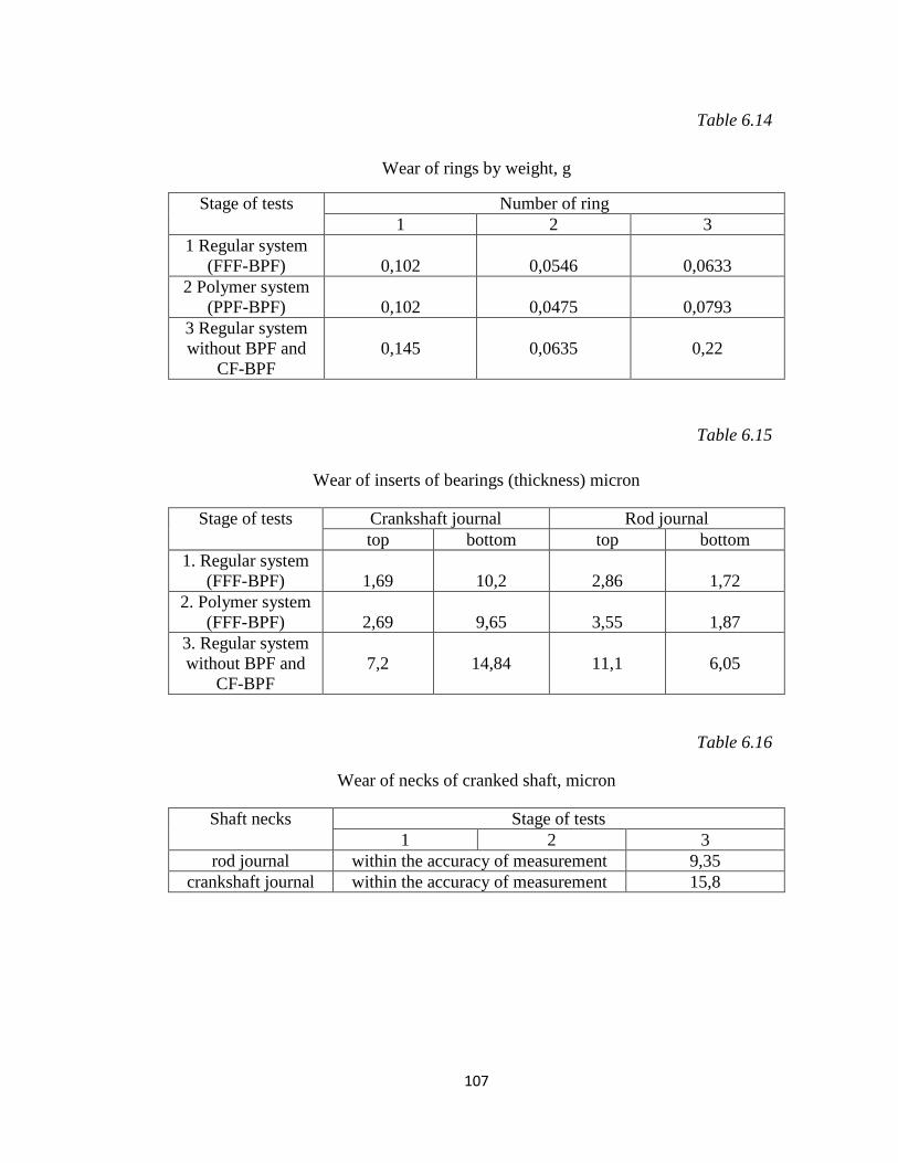
107
Table 6.14
Wear of rings by weight, g
Stage of tests Number of ring
1 2 3
1 Regular system
(FFF-BPF)
0,102
0,0546
0,0633
2 Polymer system
(PPF-BPF)
0,102
0,0475
0,0793
3 Regular system
without BPF and
CF-BPF
0,145
0,0635
0,22
Table 6.15
Wear of inserts of bearings (thickness) micron
Stage of tests Crankshaft journal Rod journal
top bottom top bottom
1. Regular system
(FFF-BPF)
1,69
10,2
2,86
1,72
2. Polymer system
(FFF-BPF)
2,69
9,65
3,55
1,87
3. Regular system
without BPF and
CF-BPF
7,2
14,84
11,1
6,05
Table 6.16
Wear of necks of cranked shaft, micron
Shaft necks Stage of tests
1 2 3
rod journal within the accuracy of measurement 9,35
crankshaft journal within the accuracy of measurement 15,8

108
Table 6.17
Wear of sleeves of cylinders, micron
Depth of belt, mm
Stage of tests
1 2 3
24,6 5,03 5,72 18,2
34 1,92 2,02 6,53
44 2,47 2,45 13,12
Based on the analysis of physical and chemical characteristics of tested engine oil,
including total contamination impurity and their components, alkalinity, sulphatic
ash-content, viscosity, balance of contamination impurity, coefficients of oil
filtration during tests, service life of filter elements before reaching their limit of
contamination and impurity of pistons, it was concluded that in operation the service
life of the oil when using the combined cleaning system (FFF+CF and FFF+BPF) is
twice longer, than when using only one full-flow filter (FFF).
In table 6.15-6.18 given data obtained from engine bench tests in relation to the wear
of engine parts, data was obtained after 120 hours of tests using various filtration
systems. It is visible that when using combined polymer filtration systems FFF+BPF
and FFF+CF the wear of engine parts considerably decreased.
6.2.2 Engine tests of VW 1.2 TSI with various oil filtration systems
Comparative engine tests of various oil filtration systems were carried out in
collaboration with the author on the VW 1.2 TSI engine using the full-flow paper
filter and the combined polymer filter consisting of the by-pass polymer filter
element designed in the form of the two layer filter element. Technical specification
of the engine VW 1.2 TSI used for laboratory tests of combined oil filtration systems
is described below:
Basic data of the engine VW 1.2 TSI
Petrol engine: VW 1.2 TSI, water cooling
Bore: 71.0 mm
Stroke: 75.6 mm
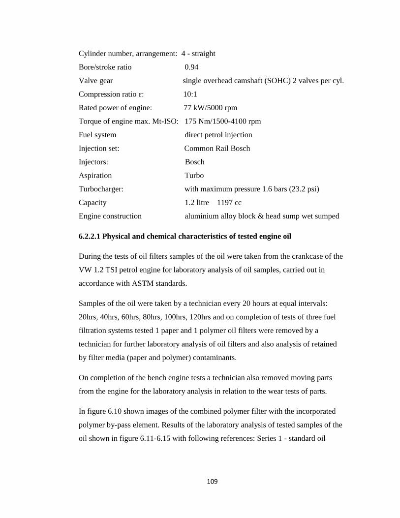
109
Cylinder number, arrangement: 4 - straight
Bore/stroke ratio 0.94
Valve gear single overhead camshaft (SOHC) 2 valves per cyl.
Compression ratio ɛ: 10:1
Rated power of engine: 77 kW/5000 rpm
Torque of engine max. Mt-ISO: 175 Nm/1500-4100 rpm
Fuel system direct petrol injection
Injection set: Common Rail Bosch
Injectors: Bosch
Aspiration Turbo
Turbocharger: with maximum pressure 1.6 bars (23.2 psi)
Capacity 1.2 litre 1197 cc
Engine construction aluminium alloy block & head sump wet sumped
6.2.2.1 Physical and chemical characteristics of tested engine oil
During the tests of oil filters samples of the oil were taken from the crankcase of the
VW 1.2 TSI petrol engine for laboratory analysis of oil samples, carried out in
accordance with ASTM standards.
Samples of the oil were taken by a technician every 20 hours at equal intervals:
20hrs, 40hrs, 60hrs, 80hrs, 100hrs, 120hrs and on completion of tests of three fuel
filtration systems tested 1 paper and 1 polymer oil filters were removed by a
technician for further laboratory analysis of oil filters and also analysis of retained
by filter media (paper and polymer) contaminants.
On completion of the bench engine tests a technician also removed moving parts
from the engine for the laboratory analysis in relation to the wear tests of parts.
In figure 6.10 shown images of the combined polymer filter with the incorporated
polymer by-pass element. Results of the laboratory analysis of tested samples of the
oil shown in figure 6.11-6.15 with following references: Series 1 - standard oil

110
filtration system with a paper filter, Series 2 – combiner oil filtration system with a
polymer by-pass filter.
The application of the combined polymer filter in the engine reduced the content of
total insoluble contamination impurity. The maximum concentration of the
contamination impurity in the crankcase of the engine equipped with the combined
polymer filter comprised 4,1% after 100 hours of operation of the engine. After 60
hours of operation of the engine with the regular oil filtration system the
concentration of the contamination impurity comprised 3,9% and after 80 hours of
operation of the engine increased to 4,7%. In figure 6.16 given the dependence of
drop of pressure of engine oil of the polymer full-flow filter and consumption of the
oil through the polymer by-pass filter on length of operation of the engine.
6.2.2.2. Quantity of deposits retained by filters and analysis of overall
performance of oil filtration systems
The component composition of the Premium Blue SAE 15W-40 oil and the
contamination impurity retained by polymer full-flow and polymer by-pass filters
given in table 6.18.
Table 6.18
Component composition of Premium Blue SAE 15W-40 oil and sludge from filters
Sample
name
Operation
time
hours
Content of components, %
oil oxyacid asphaltenes resins Sludge
Total carbenes,
carboides
unburna
bles
Oil 90 96,5 1,24 1,49 0,12 0,54 0,29 0,24
FFF 90 82,4 1,28 0,67 1,1 14,4 11,2 3,1
BPF 90 71,8 2,12 2,2 - 1,1 18,2 4,3
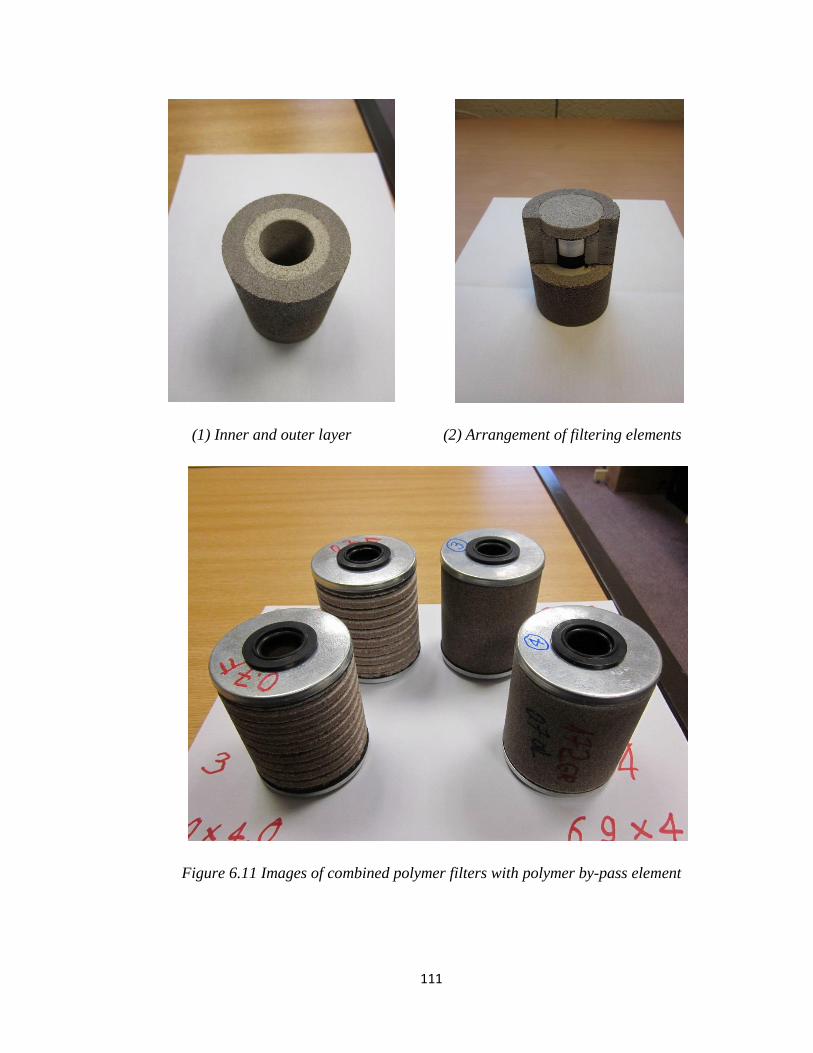
111
(1) Inner and outer layer (2) Arrangement of filtering elements
Figure 6.11 Images of combined polymer filters with polymer by-pass element

112
Figure 6.12 Physical and chemical properties of the oil, PFM 1 series 1, DC 0.9 series 2
0
1
2
3
4
5
6
0 20 40 60 80 100 120
Tota
l p
oll
uti
ng i
mp
uri
ty %
Time, hrs
0
0.2
0.4
0.6
0.8
1
1.2
1.4
1.6
1.8
0 20 40 60 80 100 120
Oxyaci
ds
%
Time, hrs
Series1 Series2
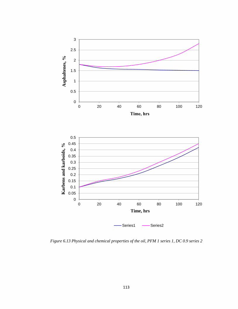
113
Figure 6.13 Physical and chemical properties of the oil, PFM 1 series 1, DC 0.9 series 2
0
0.5
1
1.5
2
2.5
3
0 20 40 60 80 100 120
Asp
halt
enes
, %
Тime, hrs
0
0.05
0.1
0.15
0.2
0.25
0.3
0.35
0.4
0.45
0.5
0 20 40 60 80 100 120
Karb
ens
an
d k
arb
oid
s, %
Тime, hrs
Series1 Series2

114
Figure 6.14 Physical and chemical properties of the oil PFM 1 series 1, DC 0.9 series 2
0
0.1
0.2
0.3
0.4
0.5
0 20 40 60 80 100 120
Un
bu
rnab
le, %
Time, hrs
0
20
40
60
80
100
120
0 20 40 60 80 100 120
Vis
cosi
ty, cS
т
Тime, hrs
Series1 Series2

115
Figure 6.15 Physical and chemical properties of the oil PFM 1 series 1, DC 0.9 series 2
0
0.5
1
1.5
2
2.5
3
3.5
4
0 20 40 60 80 100 120
Ala
kali
nit
y, m
g К
ОН
/g
Time, hrs
0
0.5
1
1.5
2
2.5
3
3.5
4
4.5
5
0 20 40 60 80 100 120
Aci
dit
y,
мg К
ОН
/g
Тime, hrs
Series1 Series2

116
Figure 6.16 Physical and chemical properties of the oil, PFM 1 series 1, DC 0.9 series 2
Figure 6.17 Dependence of drop of pressure in full-flow filter on length of tests of VW
engine, PFM 1 series 1, DC 0.9 series 2
0.5
0.7
0.9
1.1
0 20 40 60 80 100 120
Ash
es s
alf
on
ate
d, %
Тime, hrs
Series1 Series2
0
0.1
0.2
0 20 40 60 80 100 120
Dro
p o
f p
ress
ure
P
, m
Pa
Тime, hrs
Series1 Series2

117
Figure 6.18 Dependence of consumption of oil through by-pass filter on length of tests of
VW engine, PFM 1 series 1, DC 0.9 series 3
For the assessment of efficiency of operation of filters and filtration systems the
balance of the total contamination impurity found in the oil, retained by the filters,
burned and taken with samples of the oil for laboratory tests was determined.
The balance of the total contamination impurity found in the oil of the engine and
retained by filters during tests using various filters and their systems along with
values of coefficient of the oil filtration provided by various filters and their systems
given in table 3.2.
The quantity of contamination impurity found in the oil is determined by the
equation:
g1=gм + gуg + gp + gз
The coefficient of oil filtration during tests is defined by the filter as following:
0
0.2
0.4
0.6
0.8
1
1.2
1.4
1.6
1.8
2
0 20 40 60 80 100 120
Con
sum
pti
on
of
oil
l/m
in
Тime, hrs
Series1 Series2

118
1
3
g
gК i
i
where g3i - quantity of retained contamination impurity given by i - cleaner during
tests.
Then coefficient of oil filtration system of filters is defined as following:
1
3
g
gК
where g3 - quantity of the contamination impurity retained by system of filters
during tests.
From data collected in during the work carried out for this thesis, it is evident that
the largest quantity of total contamination impurity was retained when using
combined oil filtration systems, while coefficient of oil filtration of the full-flow
filter comprised 7% when using the regular system and when using the combined oil
filtration system comprised 3.5%. However total coefficient of oil filtration when
using the combined filtration system comprised 25.% as a result of high coefficient
23% of oil filtration provided by the by-pass filter. The impurity of parts of piston
group of the engine is given in table 6.20 when using various oil filtration systems.
It is visible that the use of the polymer combined oil filtration system reduced total
impurity of engine pistons.
In table 6.21-6.25 data provided in relation to the wear of moving parts of the engine
using various oil filtration systems, these systems were used during 120 hours of
engine tests. It is evident that the use of the combined polymer oil filtration system
instead of the regular paper oil filtration system allows to achieve a significant
reduction of the wear of engine moving parts by up to 3 times.

119
Table 6.19
Balance of total contamination impurity in the engine with various oil filtration
systems
Designation and
parameter unit of
measure
Regular system Polymer combined system
80 hours of test 90 hours of test
FFF FFF BPF
Х0, % 2,27 2,27
Хк, % 4,59 4,12
Хср, % 3,12 2,89
Gм, kg 9,1 9,1
gм, kg 0,206 0,161
Gуg, kg 3,47 4,09
gуg, kg 0,031 0,011
Gpr, kg 0,709 0,61
Gp, kg 0,004 0,016
Gf, dry kg 0,324 0,301 0,214
Gf, mixed kg 0,614 0,492 0,283
Gf, after tests, kg 0,712 0,542 0,494
G3, kg 0,97 0,051 0,212
X3, % 19,4 17,4 28,14
g3, kg 0,018 0,0087 0,058
g3 0,018 0,067
g1, kg 0,262 0,258
g1, g/hour 3,25 2,87
Ki, % 7,25 3,3 22,7
K, % 7,25 26,1

120
Table 6.20
Impurity of piston group parts of VW 1.2 TSI engine with various oil filtration
systems
Name of the parameter
Oil filtration systems
Regular System (FFF)
80 hours of tests
Polymer combined system
90 hours of tests
Degree of mobility of
rings
0,92
0,71
Impurity of piston flutes 1,84 1,61
Impurity of piston
crossing points
1,03
0,83
Impurity of skirt of piston 0,52 0,32
Impurity of internal
surface of head of piston
1,21
0,96
Total impurity of the
piston
5,47
4,41
Table 6.21
Average wear of piston rings on radial thickness, micron
Stage of tests Number of ring
1 2 3
1. Regular system used for 100 hrs 28,9 55,7 48,7
2. Combined system with polymer
filter used for 100 hrs
18,2
31,4
27,2
Table 6.22
Average wear of piston rings by weight, g
Stage of tests Number of ring
1 2 3
1 standard system 0,12 0,23 0,079
2 combined system 0,045 0,185 0,047

121
Table 6.23
Average wear of sleeves of cylinders, micron
Depth of belt from top of
sleeves, mm
Stage of tests
1 standard system 2 combined system
10 20,4 11,7
16 15,2 8,8
23 11,3 9,8
45 9,6 6,1
90 9,3 6,8
Table 6.24
Average wear of cranked shaft necks, micron
Shaft necks Stage of tests
1 standard system 2 combined system
rod journal 3,87 2,2
crankshaft journal 6,4 3,2
Table 6.25
Average wear of cranked shaft inserts (thickness) micron
Stage of tests Crankshaft journal Rod journal
top bottom top bottom
1 standard system 3,1 27,2 18,1 6,29
2 combined system 2,2 13,4 10,2 3,41
6.4. Conclusions
1. The analysis of designs and filter materials of by-pass filters to determine
optimum concentration of polymer composition of the outer and inner filtering
elements (PVC and PET 10х80%) was carried out. The nominal subtlety of
elimination is within 20-26 microns, porosity 77%, and oil consumption through the
filter with the throttle 2,0 mm comprised 2,8 l/min.

122
2. The contaminant retaining capacity of polymer filter elements of the by-pass
filters with dimensions of 80х100 mm (DxH) determined using quartz dust and
made of the mixture of 2 polymers (PVC/PET) comprised on average 217, operation
time before reaching reduction in oil consumption through the filter by 50%
comprised 35 hours. The polymer filter elements have satisfactory water resistance
and thermal stability.
3. Engine bench tests of combined oil filtration systems using the diesel engine
Cummins ISB e-4 demonstrated that coefficient of total contamination impurity,
when using various oil filtration systems, comprised 25%, the filtration system
consisting of one full-flow paper filter has coefficient of cleaning 7%.
4. Impurity of pistons of the Cummins ISB e-4 engine when using the combined oil
filtration system is 1,5 times less, and the wear of moving parts of the engine is up to
2 times less, than when using only the regular full-flow oil filtration system.
5. Engine bench tests of the combined polymer oil filtration system using the petrol
VW 1.2 TSI engine, showed that in comparison with the regular oil filtration system
there is a decrease in concentration of total contamination impurity by 50%
reduction of impurity of parts of piston group by 30% and decrease in the wear of
moving parts of the engine by up to 3 times. The coefficient of oil filtration
determined from balance of the contamination impurity increased to 25% in
comparison with 7% using the regular filtration system.
6. Technical requirements for the combined polymer oil filtration system were
developed, the optimum accuracy of elimination of polymer filtering material for
full-flow and by-pass filters, based on the existing level of quality of engine oils and
high dispersion of the contamination impurity was determined.

123
Chapter 7 – Conclusions and Further Work
7.1. Conclusions
Based on the analysis of the existing experience it was established that reliable
protection of bearings of internal combustion engines is achieved with the use of
effective combined oil filtration systems consisting of full-flow filters with high
filtering capacity and the by-pass filters or centrifuges with a significant contaminant
capacity and efficiency of operation. It was established that the objective assessment
of tested oil filtration systems is achieved as a result of their complex research: in
laboratory and engine bench and operational conditions. The key findings of this
project are summarized as follows:
1. Using methods of mathematical planning of experiments and analysing
existing experience in filtration field, researches of polymer and paper
filtering materials were conducted in order to determine most effective
filtering media for the application in full-flow and by-pass oil filters. The
complex of conducted researches provided sufficient data to support a
proposed application of polymer filtering material in full-flow oil filters for
internal combustion engines.
2. Extensive laboratory and engine bench tests were carried out by the author
and data collected in during the work carried out for this thesis on
completion of all tests provided sufficient evidence to demonstrate high
efficiency of oil filtration provided by a polymer filter media and compare its
performance against a paper filter media. Results of bench tests provided the
data for each type of the tested engines - diesel and petrol.
3. A novel polymer filter media for the combined oil filtration systems for
diesel and petrol engines was developed by the author. The quantitative
assessment of probability of penetration of particles of contamination in
bearings of cranked shaft and reliability of their protection with various oil
filtration systems and power setting of the engine was carried out. The high
efficiency of combined polymer oil filtration systems for diesel and petrol
engines which included full-flow filters with the use of elements made from
a polymer filter media with a high contaminant retaining capacity and by-
pass filters with polymer filtering elements was determined.
4. On completion of the research project the efficiency of full-flow and
combined oil filtration systems consisting of full-flow paper filters and by-
pass centrifuges or by-pass filters tested in various engine operating
conditions was determined. Probabilities of penetration of particles of the

124
contamination impurity in bearings of the engine and reliability of their
protection depending on sizes of contamination particles and schemes of the
oil filtration system were calculated. It was established that the essential
difference in intensity of oil filtration with various filtration systems takes
place for small particles up to 5 microns, however oil filtration of organic
particles of contamination is significantly improved with the use of the
combined filtration system consisting of the by-pass polymer filters.
5. On completion of the research project the structural change in the balance of
components was investigated and the balance of the total contamination
impurity was found in analysed samples of the oil of the tested engines and
retained by filters during tests using various filters and filtration systems
along with values of coefficient of oil filtration provided by various filters
and filtration systems
6. The conducted researches demonstrated high efficiency of combined
polymer oil filtration systems, which provided a significant decrease in
concentration of impurity contamination of the engine oil by up to 3 times
and a reduction of impurity of parts of sleeve assembly group of the engine
by up to 2 times along with a considerable decrease in the wear of bearings
of engines. It was proven that the polymer oil filter DC 0.9 with nominal
subtlety of elimination 20-26 microns allows to increase a service life of
filter elements by up to 3 times without a decrease in the reliability of
operation of the engines.
Based on results of this work 3 UK Patents were granted by the UK Intellectual
Property Office in 2012.
7.2. Further work
Based on the knowledge gained from the research conducted in this project, a
number of topics related to this area might be interesting to look into in the future.
It is necessary to look at the effect of increasing/decreasing dimensions of
polymer filtering elements of oil filters on oil filtration, because although the
current version of full-flow and by-pass polymer filters provides sufficient
level of oil filtration and exceeds performance of paper oil filters there is
need to investigate further dependence between volume of filter media and
length of operation of polymer filters.

125
It is also necessary to look at the influence of the polymer filter media on
quality of oil filtration resulting in improvement of protection of bearings of
the engine. As the oil-polymer medium interaction is a two way-process, it
would be valuable to analyse changes in condition of engine oil after longer
operational intervals to determine which additives and oil properties are
effected and how much longer the oil could be used without losing its ability
to provide reliable protection of bearings and other moving parts of the
engine.

126
8 References
[1] H. Gibson, "Fuels and Lubricants for Internal Combustion Engines - An
Historical Perspective" SAE Technical Paper 821570, 1982.
[2] I. M. Hutten, “Engine Filtration” (Transportation), Handbook of Nonwoven
Filter Media, (Second Edition), 2016, pp. 520–541.
[3] Technical Service Bulletin 90-1, “Spin-on Engine Filter applications”
Filter Manufacturers Council, Oct. 2012, pp. 1-2.
[4] “Comparison of Automotive Oil Filters” SAE International, 2010.
[5] L. Zirker, J. Francfort ”Oil bypass Filter Technology Performance
Evaluation” (First quarterly report) 2003.
[6] K. Howard, “Advanced engine oils to improve the performance of modern
internal combustion engines” Lubrizol Ltd, 2014, pp. 138-164
[7] B. N. Seth, “Lubrication in Practice” Diesel and Petrol Engine Lubrication,
1983, pp 28-49.
[8] M. M. Musthafa, “Synthetic lubrication oil influences on performance and
emission characteristic of coated diesel engine” Applied Thermal Engineering
Volume 96, Mar 2016, pp. 607–612.
[9] A. Formia, F. Villani, and F. Negro, "Double Filtration Oil Filters for
Automotive Applications" SAE Technical Paper 840453, 1984.
[10] B. Schwandt, B. Verdegan, C. Holm, S. Kelly, "Optimizing Lubricating Oil
Filtration Systems for Diesel Engines," SAE Technical Paper 930017, 1993.
[11] T. Christopher Dickenson, “Filters and filtration handbook” Oxford, Elsevier,
4th ed. 1997.
[12] N. Mohan, M. Sharma, R. and Kumar, N. Singh, "Tribological Performance of
Lubricating Oil Contaminated with Fine Dust Particles," SAE Technical Paper
2014.
[13] H. J. Ecker, J. Hahn, “New development in heavy-duty diesel engines”
Heavy-Duty Engines, MTZ worldwide February 2003, Volume 64,

127
Issue 2, pp. 2-5.
[14] “Internal combustion engine handbook basics, components, systems, and
perspectives” Society of Automotive Engineers, 2004.
[15] Christophe Guillon, Laurent Guerbe, “Soot filtration for Diesel Engine
Lubricating Oil” SAE 2010 World Congress & Exhibition, 12 April 2010.
[16] Y. Najjar, “Lubricants analysis as guide for predictive maintenance in diesel
engines” Mechanical Engineering Department, Yarmouk University, 1986,
pp. 431-434.
[17] A. Samways and I. Cox, "A Method for Meaningfully Evaluating the
Performance of a By-Pass Centrifugal Oil Cleaner" SAE Technical Paper
980872, 1998.
[18] Technical data of oil filters produced by Refilco company.
[19] Maurice E. Le Pera, George E. Oswald, “Heat transfer characteristics of
lubricants for internal-combustion engines” Industrial and Engineering
Chemistry Product Research and Development, 1974, Volume 13(3),
pp. 209-213.
[20] “Cummins Engine Oil and Oil analysis Recommendations” Service bulletin
Number 3810340, 27 Mar. 2014.
[21] D. Staley, "Correlating Lube Oil Filtration Efficiencies with Engine Wear"
SAE Technical Paper 881825, 1988.
[22] J. Feng, J. Zhang, “The Property of Automobile Engine Oil Filtration Material
and the Development of New Filter” Journal of Engineered Fibers and
Fabrics, 2014, Volume 9(3), pp. 134-141.
[23] Technical Service Bulletin 04-1, “Automotive Gasoline Engine Oil and Oil
Service Intervals” Filter Manufacturers Council, May 2011, pp. 1-2.
[24] B. Verdegan, B. Schwandt, C. Holm, and S. Fallon, "Protecting Engines and
the Environment - A Comparison of Oil Filtration Alternatives," SAE
Technical Paper 970551, 1997.
[25] Catalogue of full-flow and by-pass filters produced by FRAM company.

128
[26] Technical data of by-pass oil filters produced by IPU company.
[27] L. Pless "Interactions among Oil Additive and Engine Operating Parameters
Affecting Engine Deposits and Wear" SAE Technical Paper 720686, 1972.
[28] “Offering aftermarket engine oil filtration system” Filtration and Separation,
October 2002, Volume 39(8), p. 12.
[29] M. E. Butovskii, “Utilization of spent lube oils” Chemistry and Technology of
Fuels and Oils, Sep. 2009.
[30] Technical data of oil and by-pass filters produced by Donaldson company.
[31] Technical data of oil and by-pass filters produced by Fleetguard company.
[32] V. Reznikov, “Treating Motor Oils with By-pass Filters in Automotive
Engines” Chemistry and Technology of Fuels and Oils, 2001, Volume 37(4),
pp. 229-231.
[33] Technical data of oil and by-pass filters produced by Triple-R company.
[34] Technical data of oil and by-pass filters produced by Fleetguard company.
[35] D. Margaroni, “Extended drain intervals for crankcase lubricants”
Industrial Lubrication and Tribology, 1999, Volume 51(2), pp. 69-76.
[36] T. C. Dickenson, “Filters and Filtration Handbook”, Elsevier Advanced
Technology, 4th
Edition, 1997.
[37] R. and Rogers W. Overton, "Heavy Duty Diesel Engine Oil Filterability" SAE
Technical Paper 840344, 1984.
[38] J. Butler, J. Stewart, and R. Teasley, "Lube Oil Filtration Effect on Diesel
Engine Wear" SAE Technical Paper 710813, 1971.
[39] M. Beauchamp, "Application of High Efficiency Oil Filtration to Heavy Duty
Diesel Bus Engines" SAE Technical Paper 920927, 1992.
[40] R. D. Burke, C. J. Brace, R. I. Stark, “Investigation into the benefits of reduced
oil flows in internal combustion engines" International Journal of Engine
Research, 2014.
[41] A. Dhar, A. K. Agarwal, V. Saxena, “Measurement of dynamic lubricating
oil film thickness between piston ring and liner in a motored engine” Sensors &
Actuators, A. Physical, 2009, Volume 149(1), pp. 7-15.

129
[42] “Modelling Engine Oil Vaporization and Transport of the Oil Vapour in the
Piston Ring Pack of Internal Combustion Engines”, Powertrain & Fluid
Systems Conference & Exhibition, 2004
[43] “Review On Effects of Piston and Piston Ring Dynamics Emphasis with Oil
Consumption and Frictional Losses in Internal Combustion Engines” 8th
International Conference on Engines for Automobiles, 16 Sep. 2007.
[44] C. Peuchot, N. Petillon, J. Lynch, “Filter efficiency and liquids: The advantages
of cartridge filters” Filtration and Separation, 2008, Volume 45, pp. 11-13.
[45] Clarcor Inc. USA, “Filtration Industry Analyst” Volume 2007, Issue 12,
Dec. 2007, p. 5.
[46] International Congress & Exposition “Design and Development of the Holset
HX Series of Turbochargers” 01 Feb. 1990.
[47] István Lakatos, “Development of a new method for comparing the cold startand
the idling operation of internal combustion engines” Periodica Polytechnica
Transportation Engineering, 2015, Volume 43(4), pp. 225-231.
[48] A. Fell and A. Samways "The Development of a Novel Self-Powered
Centrifugal Oil Cleaner for Automotive Applications" SAE Technical Paper
2003.
[49] M. Anand, M. Hadfield, J. L. Viesca, B. Thomas, B. A. Hernández, S. Austen,
“Ionic liquids as tribological performance improving additive for in-
service and used fully-formulated diesel engine lubricants” Wear, 15 Jul. 2015,
Volume 334-335, pp. 67-74.
[50] Filtration 2004: Conference Programme Filtration and Separation, 2004,
Volume 41(9), pp. 35-35.
[51] D. Lamon, “The Evaluation of Mechanical Design and Comparison of
Automotive Oil Filters” California State University, 2010-01-1542,
pp. 346-355.
[52] M. W. Fay, A. L. Rocca, P. J. Shayler, Journal of Physics: Conference
Series, 2014, Volume 522(1), pp. 012072 (4pp).

130
[53] Y. A. Levendis, “Design and Testing of a Novel Environmentally-Benign
Automotive Oil Filter” Northeastern University, 2010-01-0272, 2010, pp. 1-8.
[54] M. F. Fox, “Automotive Lubricant Specification and Testing” Chemistry
and Technology of Lubricants, 05 Sep. 2009, pp. 497-552.
[55] Y. Zhang, J. Wang, F-X Ai, “Determination of the Wear of Internal
Combustion Engine Components Based on Measurement of the Oil Spectrum”
Proceedings of the Institution of Mechanical Engineers, Part D: Journal of
Automobile Engineering, 2010, Vol. 224(11), pp. 1451-1457.
[56] J. G. Eleftherakis, “Test Methods for Automotive Filtration” SAE Technical
Paper 930016, 01 Feb. 1993, pp. 1-6.
[57] R. D. Burke, C. J. Brace, J. G. Hawley, I. Pegg, “Review of the systems
analysis of interactions between the thermal, lubricant, and combustion
processes of diesel engines” Proceedings of the Institution of Mechanical
Engineers, Part D: Journal of Automobile Engineering, 2010, Volume 224(5),
pp. 681-704.
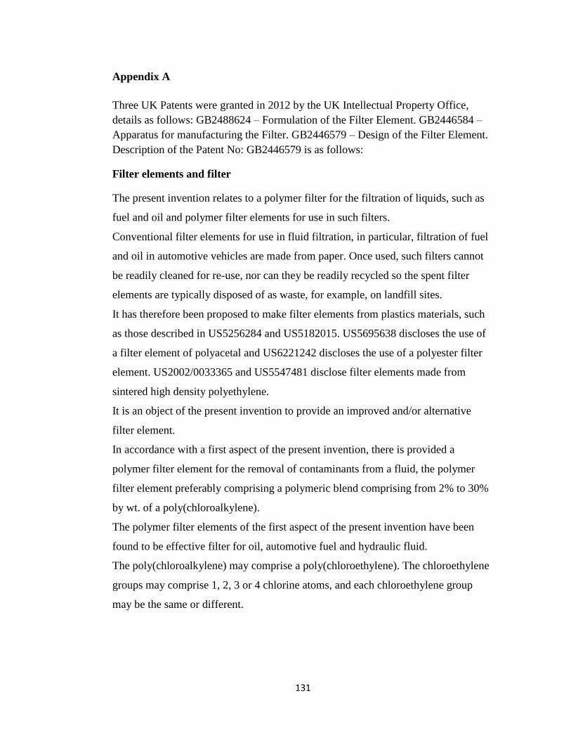
131
Appendix A
Three UK Patents were granted in 2012 by the UK Intellectual Property Office,
details as follows: GB2488624 – Formulation of the Filter Element. GB2446584 –
Apparatus for manufacturing the Filter. GB2446579 – Design of the Filter Element.
Description of the Patent No: GB2446579 is as follows:
Filter elements and filter
The present invention relates to a polymer filter for the filtration of liquids, such as
fuel and oil and polymer filter elements for use in such filters.
Conventional filter elements for use in fluid filtration, in particular, filtration of fuel
and oil in automotive vehicles are made from paper. Once used, such filters cannot
be readily cleaned for re-use, nor can they be readily recycled so the spent filter
elements are typically disposed of as waste, for example, on landfill sites.
It has therefore been proposed to make filter elements from plastics materials, such
as those described in US5256284 and US5182015. US5695638 discloses the use of
a filter element of polyacetal and US6221242 discloses the use of a polyester filter
element. US2002/0033365 and US5547481 disclose filter elements made from
sintered high density polyethylene.
It is an object of the present invention to provide an improved and/or alternative
filter element.
In accordance with a first aspect of the present invention, there is provided a
polymer filter element for the removal of contaminants from a fluid, the polymer
filter element preferably comprising a polymeric blend comprising from 2% to 30%
by wt. of a poly(chloroalkylene).
The polymer filter elements of the first aspect of the present invention have been
found to be effective filter for oil, automotive fuel and hydraulic fluid.
The poly(chloroalkylene) may comprise a poly(chloroethylene). The chloroethylene
groups may comprise 1, 2, 3 or 4 chlorine atoms, and each chloroethylene group
may be the same or different.

132
The poly(chloroalkylene) may, for example, be provided by polyvinyl chloride,
chlorinated polyvinyl chloride, plasticized polyvinyl chloride, unplasticized
polyvinyl chloride or related polymer, or a copolymer in which all or substantially
all, that is, more than 90% by weight of the copolymer is derivable from
chlorohydrocarbon monomer units.
It is preferred that at least 50% by weight (and preferably at least 80% by weight and
more preferably at least 90% by weight) of the poly(chloroalkylene) is provided by
group X having the general structure (i) below wherein A, B, E and D are H or Cl
provided that at least one of A, B, E and D is Cl.
Structure (i) is
B
A
D
E
Each repeat group X in the polymeric blend may be mutually the same. For
example, the repeat group X may always be a
–CH2-CHCl- repeat group. Alternatively, the polymeric blend may comprise repeat
groups X of mutually different structure. For example, the polymeric blend may
comprise two or more of the repeat groups –CH2-CHCl-, -CH2-CCl2-, -CHCl-CHCl-
, -CHCl-CCl2- and –CCl2-CCl2-.
The repeat group X content of the polymeric blend may substantially be provided,
for example, by polyvinyl chloride (PVC) or chlorinated polyvinyl chloride (CPVC).
It has been found that polyvinyl chloride and its related derivatives produce efficient
filters. This is of importance in that PVC and derivatives are common waste
products that may be recycled. The filter element of the present invention is not
limited to one using recycled materials; virgin materials may be used, such as
Evipol-SH, -EP and -EH polymers (Ineos Vinyls, Runcorn, UK).
Those skilled in the art will realize that the poly(chloroalkylene) may comprise
impurities or defects, such as the presence of unchlorinated branch groups (such as
methyl, ethyl and butyl), carbonyl groups and unsaturated carbon-carbon bonds. For
example, a polyvinyl chloride, chlorinated polyvinyl chloride, plasticized polyvinyl

133
chloride, unplasticized polyvinyl chloride or related polymer may comprise up to
5% (and preferably up to 1%) by weight of groups having a structure other than a
chloroethylene structure (chloroethylene meaning –CH2-CHCl-, -CH2-CCl2-, -
CHCl-CHCl-, -CHCl-CCl2- or –CCl2-CCl2-).
It is preferred that the polymeric blend comprises from 2% to 20% by weight of the
poly(chloroalkylene), preferably from 2% to 15%, more preferably from 3% to 12%,
further more preferably from 4% to 12% and most preferably from 8% to 12% by
weight of the poly(chloroalkylene).
It is preferred that the polymeric blend comprises from 60 to 98% (preferably from
70 to 95%, more preferably from 80 to 90% and most preferably from 80 to 85%) by
weight of a further thermoplastic. It is preferred that the further thermoplastic
comprises one or more of poly acrylonitrile butadiene styrene, acrylic, celluloid,
cellulose acetate, a polyester (such as poly ethylene vinyl acetate, a polyacrylate and
a terephthalate [e.g. polybutylene terephthalate, polyethylene terephthalate and
polycyclohexylene dimethylene terephthalate], polyhydroxyalkanoates), poly
ethylene vinyl alcohol, fluoroplastics (for example, polyfluorotetraethylene
(PTFE)), polyacetal , polyacrylonitrile, polyamide (such as nylon), polyamide-imide,
polyaryletherketone, polybutadiene, polybutylene, , polycarbonate, polyketone,
polyethylene, polyetheretherketone, polyetherimide, polyethersulfone,
polyethylenechlorinates, polyimide, polylactic acid, polymethylpentene,
polyphenylene oxide, polyphenylene sulfide, polyphthalamide, polypropylene,
polystyrene and polysulphone.
It is preferred that the further thermoplastic comprises one or more of a polyamide, a
polyester (such as a terephthalate) and a polyalkylene. The polyamide may be a
nylon, such as nylon 6,6. The polyalkylene may be polypropylene or polyethylene,
for example. The polyalkylene terephthalate may be polyethylene terephthalate.
The polyalkylene may be a high density or a low density polyalkylene. Examples of
high density polyethylenes include HMA 014, HMA 025 and HMA 035 (Exxon
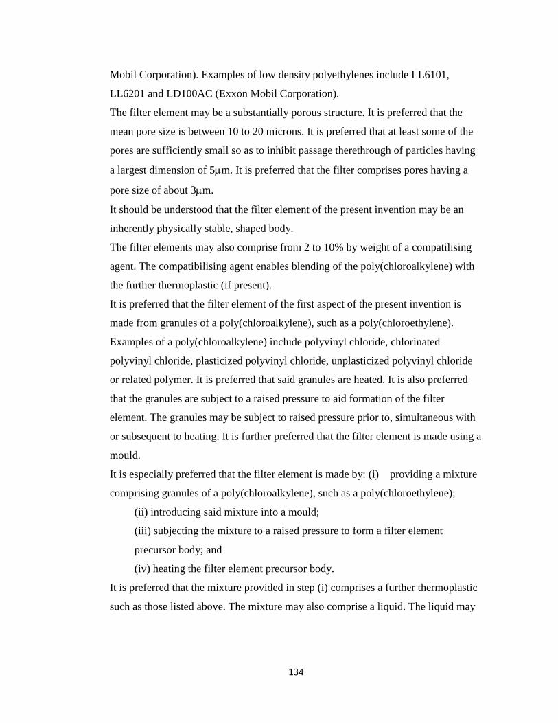
134
Mobil Corporation). Examples of low density polyethylenes include LL6101,
LL6201 and LD100AC (Exxon Mobil Corporation).
The filter element may be a substantially porous structure. It is preferred that the
mean pore size is between 10 to 20 microns. It is preferred that at least some of the
pores are sufficiently small so as to inhibit passage therethrough of particles having
a largest dimension of 5m. It is preferred that the filter comprises pores having a
pore size of about 3m.
It should be understood that the filter element of the present invention may be an
inherently physically stable, shaped body.
The filter elements may also comprise from 2 to 10% by weight of a compatilising
agent. The compatibilising agent enables blending of the poly(chloroalkylene) with
the further thermoplastic (if present).
It is preferred that the filter element of the first aspect of the present invention is
made from granules of a poly(chloroalkylene), such as a poly(chloroethylene).
Examples of a poly(chloroalkylene) include polyvinyl chloride, chlorinated
polyvinyl chloride, plasticized polyvinyl chloride, unplasticized polyvinyl chloride
or related polymer. It is preferred that said granules are heated. It is also preferred
that the granules are subject to a raised pressure to aid formation of the filter
element. The granules may be subject to raised pressure prior to, simultaneous with
or subsequent to heating, It is further preferred that the filter element is made using a
mould.
It is especially preferred that the filter element is made by: (i) providing a mixture
comprising granules of a poly(chloroalkylene), such as a poly(chloroethylene);
(ii) introducing said mixture into a mould;
(iii) subjecting the mixture to a raised pressure to form a filter element
precursor body; and
(iv) heating the filter element precursor body.
It is preferred that the mixture provided in step (i) comprises a further thermoplastic
such as those listed above. The mixture may also comprise a liquid. The liquid may

135
be present up to 5% by weight of the weight of the mixture, more preferably up to
2%, and further more preferably from 0.02 to 1%. The liquid has been found to ease
removal of the filter element from the mould.
The mixture may also comprise from 2 to 10% by weight of a compatilising agent.
The compatibilising agent enables blending of the poly(chloroalkylene) with the
further thermoplastic (if present).
In accordance with a second aspect of the present invention there is provided a filter
comprising a filter element in accordance with the first aspect of the present
invention and a filter housing for accommodating the filter element for use.
In accordance with a third aspect of the present invention, there is provided there is
provided a method of making a filter element, said method comprising:
(i)providing a mixture comprising a plastics material;
(ii) introducing said mixture into a mould;
(iii) subjecting the mixture to a raised pressure to form a filter element
precursor body; and
(i) heating the filter element precursor body.
The method of the third aspect of the present invention is a preferred method of
making the filter element of the first aspect of the present invention.
The mixture may comprise a liquid. The liquid may be present up to 5% by weight
of the weight of the mixture, more preferably up to 2%, and further more preferably
from 0.02 to 1%. The liquid has been found to ease removal of the filter element
from the mould.
It is anticipated that step (iv) may remove some or all of the liquid from the filter
element precursor body. For example, some of the fluid may be retained.
It is preferred that the mixture comprises from 2% to 30% by wt. of a
poly(chloroalkylene), such as a poly(chloroethylene). The chloroethylene groups
may comprise 1, 2, 3 or 4 chlorine atoms, and each chloroethylene group may be the
same or different.

136
The poly(chloroalkylene) may, for example, be polyvinyl chloride, chlorinated
polyvinyl chloride, plasticized polyvinyl chloride, unplasticized polyvinyl chloride
or related polymer, or a copolymer in which all or substantially all, that is, more than
90% by weight of the copolymer is derivable from chlorohydrocarbon monomer
units.
It is preferred that at least 50% by weight (preferably at least 80% by weight and
more preferably at least 90% by weight) of the poly(chloroalkylene) is provided by
group X having the general structure (i) as shown above in relation to the first aspect
of the present invention, wherein A, B, E and D are H or Cl provided that at least
one of A, B, E and D is Cl.
Each repeat group X may be mutually the same. For example, the repeat group X
may always be a –CH2-CHCl- repeat group. Alternatively, the mixture may
comprise repeat groups X of mutually different structure. For example, the mixture
may comprise two or more of the repeat groups –CH2-CHCl-, -CH2-CCl2-, -CHCl-
CHCl-, -CHCl-CCl2- and –CCl2-CCl2-.
The repeat group X may substantially be provided, for example, by polyvinyl
chloride (PVC) or chlorinated polyvinyl chloride (CPVC). It has been found that
polyvinyl chloride and its related derivatives produce efficient filters. This is of
importance in that PVC and derivatives are common waste products that may be
recycled. The filter element of the first aspect of the present invention and the
method of the third aspect of the present invention are not limited to the use of
recycled materials; virgin materials may be used, such as Evipol-SH, -EP and -EH
polymers (Ineos Vinyls, Runcorn, UK).
It is preferred that the mixture comprises from 2% to 20% by weight of
poly(chloroalkylene), preferably from 2% to 15%, more preferably from 3% to 12%,
further more preferably from 4% to 12% and most preferably from 8% to 12% by
weight of polychloroalkylene.
It is therefore preferred that the mixture comprises from 2% to 20% by weight of
group X, preferably from 2% to 15%, more preferably from 3% to 12%, further

137
more preferably from 4% to 12% and most preferably from 8% to 12% by weight of
group X.
It is preferred that the mixture comprises from 60 to 98% (preferably from 70 to
95%, more preferably from 80 to 90% and most preferably from 80 to 85%) by
weight of a further thermoplastic. It is preferred that the further thermoplastic
comprises one or more of poly acrylonitrile butadiene styrene, acrylic, celluloid,
cellulose acetate, a polyester (such as poly ethylene vinyl acetate, a polyester [e.g.
polybutylene terephthalate, polyethylene terephthalate and polycyclohexylene
dimethylene terephthalate] and a polyacrylate), poly ethylene vinyl alcohol,
fluoroplastics (for example, polyfluorotetraethylene (PTFE)), polyacetal ,
polyacrylonitrile, polyamide (such as nylon), polyamide-imide, polyaryletherketone,
polybutadiene, polybutylene, polycarbonate, polyhydroxyalkanoates, polyketone,
polyester, polyethylene, polyetheretherketone, polyetherimide, polyethersulfone,
polyethylenechlorinates, polyimide, polylactic acid, polymethylpentene,
polyphenylene oxide, polyphenylene sulfide, polyphthalamide, polypropylene,
polystyrene and polysulphone. It is preferred that the further thermoplastic
comprises one or more of a polyamide, a polyester (such as a terephthalate) and a
polyalkylene. The polyamide may be a nylon, such as nylon 6,6. The polyalkylene
may be polypropylene or polyethylene, for example. The polyalkylene terephthalate
may be polyethylene terephthalate. The polyalkylene may be a high density or a low
density polyalkylene. Examples of high density polyethylenes include HMA 014,
HMA 025 and HMA 035 (Exxon Mobil Corporation). Examples of low density
polyethylenes include LL6101, LL6201 and LD100AC (Exxon Mobil Corporation).
It is preferred that the mixture further comprises from 2 to 10% by weight of a
compatilising agent. The compatibilising agent enables blending of the
poly(chloroalkylene) with the further thermoplastic (if present).
The plastics material (such as the polyvinyl chloride, chlorinated polyvinyl chloride,
plasticized polyvinyl chloride, unplasticized polyvinyl chloride or related polymer or
further thermoplastic) may be supplied in step (i) in a granular form. The granules

138
may have a mean largest dimension of from 0.1mm to 1mm and preferably from 0.2
to 0.6mm. It is anticipated that in many circumstances the mixture will comprise
granules of different sizes. For example, several granular sizes of PVC may be used
to make-up the PVC component of the mixture (if PVC is present).
If a poly(chloroalkylene) such as polyvinyl chloride, chlorinated polyvinyl chloride,
plasticized polyvinyl chloride, unplasticized polyvinyl chloride or related polymer is
used in the present method, it is preferred that such material is provided in a granular
form in step (i). It is preferred that the mean largest dimension of said granules of
the poly(chloroalkylene) is from 0.2 to 0.8mm, and preferably from 0.2 to 0.6mm.
If a further thermoplastic is provided, then it is preferred that it is provided in step (i)
in granular form. The mean largest dimension of the granules of the further
thermoplastic may be from 0.2 to 1mm and preferably from 0.3 to 0.8mm.
Step (iv) may comprise heating the filter element precursor body to a maximum
temperature of 120ºC, more preferably to a maximum temperature of from 80ºC to
110ºC. It is preferred that step (iv) is performed at ambient pressure i.e. not under
reduced or increased pressure.
In step (iii), the material may be under compression for from 0.2 to 1.0 seconds,
more preferably from 0.2 to 0.6 seconds and most preferably from 0.3 to 0.5
seconds. It has been found that the application of pressure over a short timescale is
beneficial to the formation of filter elements with suitable pore sizes that enable the
filter elements to be used as oil and fuel filters.
The maximum compressive force applied in step (iii) is preferably from 10kN to
1000kN, more preferably from 10kN to 100kN and most preferably from 10kN to
150kN. In certain circumstances, in particular for the production of larger filter
elements, a maximum compressive force of from 30kN to 500kN (and more
preferably from 30kN to 150kN) may be preferred.
The mould determines the shape of the filter element precursor body. One or more
of the surfaces of the mould which, in use, comes into contact with the mixture
comprising a plastics material may have a low surface energy. A low surface energy
139
may be provided by a substrate that has been coated with a material that provides a
low surface energy. Alternatively, a substrate of a material that provides a low
surface energy may be used. Materials that provide a low surface energy include
polytetrafluoroethylene (PTFE, such as Teflon®). Surfaces with a low surface
energy may be formed by coating a substrate with a silane or polytetrafluoroethylene
(PTFE, such as Teflon®).
The mould may be shaped so as to form a cylindrical filter element precursor body.
The mould may also be provided with one or more end-fitting casting elements to
prevent egress of mixture from the mould once the filter element precursor body has
been formed in step (iii). This is important if the mould containing the filter element
precursor body is physically removed from an apparatus so that the mould-precursor
element ensemble can be put into an oven or the like to perform step (iv).
The method may further comprise providing a tamper for compressing the mixture
in step (iii). The tamper may comprise a tamping head for contacting the mixture
and a means for urging the tamping head into compressive contact with the mixture.
The means for urging the tamping head into compressive contact with the mixture
may comprise a piston. It is preferred that the piston is electrically driven. This
facilitates the tamping head to be brought into contact with, and removed from, the
material quickly. Such rapid movement has been found to be beneficial to the
formation of filter elements. It has been discovered that certain other pistons (for
example, a hydraulic driven piston) do not facilitate the rapid movement of the
tamping head. The tamping head may have an annular shape. This is of particular
benefit in the manufacture of filter elements for oil or fuel filters.
The method may further comprise providing a return mechanism for urging the
tamping head away from the mixture in the mould. Such a return mechanism may
comprise a bias means, such as a spring. A helical spring may conveniently be used,
for example. When the tamping head is urged into compressive contact with the
material the return mechanism acts so as to try to urge the tamping head away from
the mixture in the mould. Once the force urging the tamping head into contact with

140
the mixture in the mould is removed, the return mechanism urges the tamping head
away from the mixture.
The method may further comprise providing a conveyor for moving said mixture
comprising a plastics material towards the mould. The conveyor may comprise a
screw conveyor. A screw conveyor has been found to provide an effective
mechanism for moving mixtures having the consistency of paste towards the mould.
The method may further comprise providing a receiver for guiding the mixture into
the mould. The receiver may be placed adjacent the mould. The receiver may flare
outwardly, and, for example, may have a funnel like portion. The receiver may
receive the mixture from the conveyor, if present.
The method may comprise providing a plurality of moulds. The method may further
comprise providing a transporter for moving the moulds into a position in which
material may be delivered into the moulds.
The method of the third aspect of the present invention may be used to make the
filter element in accordance with the first aspect of the present invention.
Conventional filter elements are provided with a material having essentially the
same permeability to particles. Such filter elements are typically used in filters
having an inlet for the introduction of unfiltered fluid and an outlet for the egress of
filtered fluid. During normal operation, fluid passes through the filter element,
removing particles from the fluid. Under certain circumstances, fluid does not
readily pass through the filter element and pressure builds-up on the unfiltered side
of the device. This pressure build-up may occur, for example, because the filter
element is blocked, the vehicles is operating at high speed or the fluid is more
viscous than during normal operation (e.g. at start-up of a vehicle). Such pressure
build-up in a filter can be dangerous and so filters are often provided with valves
which are operable at a threshold pressure to allow unfiltered fluid to flow from the
fluid inlet to the fluid outlet without passing through the filter element. This means
that unfiltered fluid is transmitted out of the filter, and this may be damaging to the
machinery to which the unfiltered fluid is transmitted.

141
The present invention provides a filter element that mitigates the problems of
conventional filter elements mentioned above.
Falling outside the scope of the present invention there is a filter element for the
removal of contaminants from a fluid, the filter element comprising:
(i) a filter inlet for the ingress of unfiltered fluid into a chamber for the receipt of
unfiltered fluid;
(ii) a filter outlet for the egress of filtered fluid from a chamber for the receipt of
filtered fluid;
(iii) a polymer filter element located in the fluid flow path between the chamber for
the receipt of unfiltered fluid and the chamber for the receipt of filtered fluid, the
polymer filter element comprising:
(a) a first portion of the polymer filter element having a first permeability
3µm - 30µm to contaminants present in the unfiltered fluid,
(b) a second portion of the polymer filter element having a second
permeability 30µm - 40µm to contaminants present in the unfiltered
fluid, the second permeability being greater than the first permeability,
and
(c) a valve associated with the second portion, the valve being operable so
that, below a threshold pressure level in the chamber for the receipt of
unfiltered fluid, the valve inhibits transmission of fluid from the chamber
for the receipt of unfiltered fluid to the outlet via the second portion of
the polymer filter element, and, above a threshold pressure in the
chamber for the receipt of unfiltered fluid, the valve permits transmission
of fluid from the chamber for the receipt of unfiltered fluid to the outlet
via the second portion of the polymer filter element.
The valve may be operable from the first to the second valve state by the application
of a force greater than a threshold force.
In the filter element falling outside the scope of the present invention, the filter
element comprises two portions of differing permeabilities. The valve is associated

142
with the second portion of the filter element, the second portion of the filter element
having a greater permeability than the first portion. During normal operation of the
filter element, fluid passes through the first portion of the filter element, thereby
filtering the fluid. During normal operation, the valve is closed and so fluid cannot
pass through the valve and the second portion of the filter element.
Under certain circumstances, the first portion of the filter element may not operate
effectively. For example, if the fluid is cold and viscous, it may not adequately pass
through the first portion of the filter element. Likewise, if the first portion of the
filter element becomes blocked, fluid may not adequately pass through the first
portion of the filter element. This may cause the pressure in a filter, of which the
filter element forms a part, to increase. When a certain pressure is reached, the force
acting on the valve is greater than a threshold force, and the previously-closed valve
is opened to permit fluid flow through the valve and through the second portion of
the filter element. This reduces the pressure in the filter, therefore decreasing the
chance of the filter exploding. Furthermore, the fluid is also filtered before it reaches
the outlet of a filter of which the filter element forms a part.
Falling outside the scope of the present invention, there is a filter for the removal of
contaminants from a fluid, the polymer filter comprising:
(i) a filter inlet for the ingress of unfiltered fluid into a chamber for the receipt of
unfiltered fluid;
(ii) a filter outlet for the egress of filtered fluid from a chamber for the receipt of
filtered fluid;
(iii) a polymer filter element located in the fluid flow path between the chamber for
the receipt of unfiltered fluid and the chamber for the receipt of filtered fluid, the
polymer filter element comprising:
(a) a first portion of the polymer filter element having a first permeability
3µm - 30µm to contaminants present in the unfiltered fluid,
(b) a second portion of the polymer filter element having a second
permeability 30µm - 40µm to contaminants present in the unfiltered fluid,

143
the second permeability being greater than the first permeability, and
(c) a valve associated with the second portion, the valve being operable so
that, below a threshold pressure level in the chamber for the receipt of unfiltered
fluid, the valve inhibits transmission of fluid from the chamber for the receipt of
unfiltered fluid to the outlet via the second portion of the polymer filter element,
and, above a threshold pressure in the chamber for the receipt of unfiltered fluid, the
valve permits transmission of fluid from the chamber for the receipt of unfiltered
fluid to the outlet via the second portion of the polymer filter element.
The valve may conveniently be located on the side of the second portion facing or
forming the chamber for the receipt of filtered liquid. Alternatively, the valve may
conveniently be located on the side of the second portion facing or forming the
chamber for the receipt of unfiltered liquid.
The filter element may be arranged so that, when the valve is open, fluid may pass
from the chamber for the receipt of unfiltered fluid, through the second portion of
the filter element, before passing through the valve to the chamber for the receipt of
filtered fluid.
Alternatively, the filter element may be arranged so that, when valve is open, fluid
may pass from the chamber for the receipt of unfiltered fluid, through the valve,
before passing through the second portion of the filter element and into the chamber
for the receipt of filtered fluid.
For the avoidance of confusion, it is hereby stated that the following statements
apply to both elements falling outside the scope of the present invention.
It is preferred that the first portion of the filter element has a first permeability to
particles present in an unfiltered fluid and the second portion of the filter element
has a second permeability to particles present in an unfiltered fluid, the second
permeability being greater than the first permeability. This is often conveniently
achieved by the first and second portions of the filter element having a porous
structure, the pores of the second portion of the filter element being larger than the
pores of the first portion of the filter element.

144
It is preferred that the filter element is a filter for the filtration of liquids, such as a
fuel, oil or hydraulics fluid filter.
The valve may comprise a slit valve. Advantageously, the valve may comprise a
valve member which is biased into sealing engagement with a valve seat. The valve
member is movable away from the valve seat by a pressure in the chamber for the
receipt of unfiltered fluid that is above the threshold level (corresponding to a force
above a threshold value in relation to the filter element falling outside the scope of
the present invention) so that the sealing engagement is broken, permitting fluid
flow from the chamber for the receipt of unfiltered fluid to the outlet via the second
portion of the filter element.
The filter element may comprise a substantially tubular structure, such as a hollow
cylindrical structure. The first portion may be provided by the substantially tubular
structure. The second portion may be provided by a covering or capping structure.
The covering or capping structure may be in the form of a disk.
It is preferred that the smallest particles that may be removed from the fluid by the
first portion of the filter element are smaller than the smallest particles that may be
removed from the fluid by the second portion of the filter element. For example, the
smallest particles that may be removed by the first portion of the filter element may
have a largest dimension of about 5m. In this case, it may be desirable for the
smallest particles that may be removed by the second portion of the filter element to
have a largest dimension of about 15m.
Reference to the smallest particles that may be removed by a portion of the filter
element refers to the filter element in its initial, clean operating state. A dirty or
partially blocked filter will obviously inhibit passage therethrough of particles which
it may have permitted to pass when in a clean state. The filter element may be
provided with a cavity between the second portion of the filter element and the
valve. Such a cavity may be formed by a cover placed in sealing engagement with
the second portion of the filter element.
The filter element may be inherently physically stable.

145
The first portion and the second portion of the filter element may be provided by a
filter element body. The filter element body may be made from plastics material.
The filter element body may, for example, be made from a polyethylene as described
in US5547481 or in US2002/0033365.
The filter element may be a filter element in accordance with the first aspect of the
present invention. The filter element may be made in accordance with the method of
the third aspect of the present invention.
The present invention is now described by way of example only with reference to
the following figures of which:
Figure 1 is a schematic side view of an apparatus used to make an embodiment of a
polymer filter element according to claim 1;
Figure 2A is a cut-away view of a mould and the tamping portion of the apparatus of
Figure 1;
Figure 2B is a side-on view of a part of the apparatus of Figure 1; and
Figure 3 is a schematic cross-section through an embodiment of a polymer filter
comprising a polymer filter element according to claim 1.
Figure 1 shows a schematic representation of an apparatus used to make an
embodiment of a polymer filter element. The apparatus is denoted generally by
reference numeral 1001. The apparatus is now briefly described with reference to
Figure 1. The apparatus comprises a chute 1002 into which a mixture comprising a
plastics material may be fed. The chute 1002 guides the mixture into a screw
conveyor 1003. The electrically powered screw conveyor moves the mixture into a
mould 1008a via a receiver 1007 which acts as a funnel to direct the mixture to the
mould. Mould 1008a is one of four moulds mounted on a turntable platter 1010
driven by turntable motor 1011, but only two of the moulds (1008a, 1008b) are
shown for the purposes of clarity. The turntable platter 1010 is rotated by the
turntable motor 1011 to move respective moulds into (and out of) the mixture-
receiving position underneath the end of the screw conveyor 1003. Mould 1008a is
shown in Figure 1 as being in the mixture-receiving position. An indexing pin 1012

146
engages with a locking hole (reference numeral 1029 in Figure 2a) in the turntable
platter 1010 to prevent unwanted movement of the turntable platter 1010 once a
mould is located in the mixture-receiving position. An indexing pin driver 1013
causes the indexing pin to engage with the locking hole.
When in the mixture-receiving position, the mould 1008a is aligned with a tamper
1004 that is used to compress the mixture in the mould 1008a to form a filter
element precursor body. Once the mixture in a mould has been compressed, the
indexing pin 1012 is withdrawn to permit rotation of the turntable platter 1010,
moving an empty mould into the mixture-receiving position and moving the mould
containing the filter element precursor body into an unloading position.
The operation of the apparatus is controlled by control panel 1015.
The structure of the moulds 1008a, 1008b and the portion of the apparatus
associated with tamping will now be described in more detail with reference to
Figures 1 and 2a. Figure 2a shows a cut-away diagram of the tamper 1004, with a
mould 1008a in a mixture-receiving position. The mould 1008a comprises a
cylindrical outer wall 1031 and a cylindrical inner piece 1009a. At the lower end of
the mould 1008a, an annular end-piece 1030 extends between the outer wall 1031
and the inner piece 1009a. The inner piece 1009a, outer wall 1031 and end-piece
1030 form a receptacle for the receipt of the mixture comprising a plastics material.
The surfaces of the inner piece 1009a and the outer wall 1031 that come into contact
with the mixture have been coated with a low energy material (in this case,
polytetrafluoroethylene). This low energy material helps resist adhesion of the
mixture and any subsequently-produced filter element to the walls of the mould
1008a. The lowermost part of the inner piece 1009a locates in a cavity 1028 in the
turntable platter 1010 provided for accurate and convenient siting of a mould.
Once the mixture has been delivered to the mould 1008a via the receiver 1007, the
mixture may be compressed. The tamper 1004 comprises a cylindrical tamping
member 1006 which is provided with an annular tamping head 1022. The tamping
member 1006 and tamping head 1022 are sized so that they may be received in the

147
gap between the mould inner piece 1009a and the mould outer wall 1031. The
electrically-operated piston 1020 engages with the tamping member 1006 and urges
the tamping head 1022 into compressive contact with the material in the mould
1008a.
The apparatus is provided with a return mechanism in the form of a helical spring
1025 mounted around a cylindrical insert 1026. When the tamping member 1006 is
urged towards the mould 1008a, the lower end of the helical spring 1025 abuts
against the upper surface of lip 1027 provided on the mould inner piece 1009a. The
upper end of the helical spring 1025 abuts against the tamping member 1006. As the
tamping member 1006 is urged further downwards the helical spring 1025 becomes
more compressed, increasing the force in the spring 1025. Once the piston 1020 is
retracted, the compressed spring 1025 urges the tamping member 1006 away from
the mould 1008a. The cylindrical insert 1026 is provided to support the spring 1025.
The tamping member 1006 is provided with two fill-level pins 1023a, 1023b which
protrude through fill-level slots 1024a, 1024b respectively provided in cylindrical
body 1005. This arrangement may also be seen in Figure 2B. Referring to Figure
2A, during compression, the tamping member 1006 is moved onto the mixture. The
displacement of the tamping member 1006 is dictated primarily by the amount of
mixture in the mould 1008a. The position of the fill-level pins 1023a, 1023b are
indicative of the amount of mixture in the mould 1008a, and (referring to Figure 2B)
the position of the fill-level pin 1023a relative to the scale 1032 provided on the
body 1005 permits the user to verify that the correct amount of mixture has been
loaded into the mould 1008a.
The cylindrical body 1005 is sized so that it may abut against the end of the mould
outer wall 1031.
The piston 1020 is associated with a piston cover 1021. The piston cover is
cylindrical and sized to that it may abut against cover 1005.
Those skilled in the art will realize that the gaps shown in Figure 2a between
different elements of the apparatus have, in many cases, been exaggerated for the

148
purposes of clarity. The true gaps between elements are, in many cases, smaller than
those shown.
Those skilled in the art will realize that the moulds 1008a, 1008b are not part of the
apparatus in accordance with the present invention.
The operation of the apparatus of Figure 1 will now be described in further detail
with reference to Figures 1, 2A and 2B.
An empty mould 1008a is in a mixture-receiving position. The turntable is locked in
this position by indexing pin 1012 which is inserted into locking hole 1029.
A mixture comprising a plastics material is formed by mixing 10% by weight of
granules of polyvinyl chloride (PVC), 80% by weight of granules of polyethylene
terephthalate (PET), 8-9% by weight of a commercially available compatibilising
agent and 0.02-2% by weight of a liquid (typically an organic acid). The
compatibilising compound facilitates the blending together of PET and PVC.
Examples of such compatibilising agents include modified polyolefins (“Elvaloy”,
“Fusabond”, “Surlyn” and “Elvanol” agents from DuPont) and styrenic block
copolymers (“Styrolux” and “Styroflex” from BASF). Other compatibilising agents
of interest are polycaprolactones (such as the TONE P-767 and P-787
polycaprolactones from Dow Chemical Company). Also of particular interest are the
block-graft copolymers disclosed as compatibilisers in Polymer, Vol. 37, No. 17,
August 1996, page 3871-3877 (Braun et al.). Chlorinated polyethylenes have also
been recognized as having compatibilising properties in a PVC/high density
polyethylene mixture.
The liquid essentially acts as a lubricant to reduce the likelihood of material sticking
to the mould. Examples of liquids which may conveniently be used are organic
acids, such as acetic acid.
The liquid content is so small that the mixture has a powdery, granular consistency.
The mixture is delivered via chute 1002 to the screw conveyor 1003. The screw
conveyor transfers the mixture to mould 1008a, via a receiver 1007. It is desirable to
use the mixture shortly after preparation; leaving the mixture to stand may result in

149
the liquid evaporating. Once the appropriate amount of mixture had been delivered
to the mould 1008a, the mixture may be compressed. Piston 1020 contacts tamping
member 1006 and urges tamping head 1022 into the gap between the mould inner
piece 1009a and the mould outer wall 1031. The tamping head 1022 is urged into
compressive contact with the mixture in the mould 1008a, and the mixture is
compressed to form a filter element precursor body. The piston is then withdrawn,
and the return mechanism provided by the helical spring 1025 ensures that the
tamping member is retracted from the mould 1008a.
The maximum force applied during the compression stroke is of the order of 50-
100kN. The mixture is under compression for a period of about 0.5 seconds. The
piston is electrically actuated. It has been found that a hydraulically-actuated piston
may be used but applies a force over a longer timescale, the resulting filter element
being less satisfactory than if an electrically-actuated piston is used.
The indexing pin 1012 is then removed from the locking hole 1029 and the turntable
rotated so that an empty mould (not shown) is located in the mixture-receiving
position and mould 1008a, containing the filter element precursor body, being
moved to an unloading position. The mould 1008a is then removed from the
turntable platter 1010 and placed in an oven (not shown) so that the filter element
precursor body may be heated. The filter element precursor body is heated to 100ºC
and kept at 100ºC for 20 minutes. The temperature is then reduced to 60ºC and kept
at 60ºC for 30 minutes. The temperature is then reduced to 40ºC and kept at 40ºC for
30 minutes. The temperature is then reduced to 20ºC, and kept at 20ºC for 40
minutes. The filter element may then be removed from the mould; this process
includes removing the end-piece 1030 from the filter element. It is expected that the
heating process removes substantially all of the liquid from the filter element.
The size of the pores in the filter element may be varied by varying the relative
proportions of PVC and PET used. The size of the pores may also be varied by
varying the size of the granules of PVC and PET used, the smaller the granules the
smaller the pores in the filter element.

150
Those skilled in the art will realize that the apparatus of Figure 1 is merely
exemplary. It may be more efficient to provide a conveyor belt or the like with many
moulds which are subsequently filled with paste. The filled moulds may then be
moved to a tamping station provided with one or more tampers. Once tamped, the
filter element precursors may be moved to a heating station where the filter elements
precursors are heated to remove some or all of the fluid (if initially present). Such an
apparatus may be substantially automated.
The method described above may be readily adapted in order to change the
properties of the filter element. For example, changing the composition of the
plastics material can be used to change the properties of the filter element. For
example, increasing the mean maximum dimension of the PVC granules used in the
mixture gives rise to an increase in pore size. An increase in pore size has been
observed when one replaces 0.5mm PVC granules in a mixture with 0.8mm PVC
granules.
The method described above with reference to Figures 1, 2A and 2B describes the
manufacture of a tubular portion of a polymer filter element. As described below, an
embodiment of the polymer filter element may typically comprise a tubular portion
(the manufacture of which has been described above) and a disk-shaped cap portion.
The disk-shaped cap portion may be made using the same general apparatus and
method as described above, but using a different mould. Those skilled in the art
would also realize that a different tamper head (having a circular end shape) would
also be required. The disk-shaped cap portion may have a different permeability to
particles than the cylindrical portion. This may be achieved by the cap portion
having a different (typically greater) mean pore size than the cylindrical portion. As
explained above, this may typically be achieved by using polymer granules of
different size and/or by varying the proportion of PET and PVC.
Figure 3 shows a schematic cross-section through an embodiment of a polymer filter
comprising a filter element in accordance with the present invention. The polymer
filter (in this case, an oil filter generally denoted by reference numeral 100)

151
comprises a polymer filter element 101 disposed within a housing 102. The space
between the filter element 101 and the housing defines a chamber 105 for the receipt
of unfiltered fluid. Six inlets (only two of which are labeled using reference
numerals 150, 151) are provided to allow unfiltered fluid into the chamber 105. The
inlets 150, 151 are provided by holes formed in an annular inlet plate 152. The
polymer filter element 101 provides a filtration barrier between the chamber 105 for
the receipt of unfiltered fluid and a chamber 106 for the receipt of filtered fluid.
Egress of fluid from the chamber 106 is via outlet 200 for the egress of filtered fluid.
Polymer filter element 101 is mounted in sealing engagement with an annular plate
170.
A helical spring 120 is provided to urge the polymer filter element 101 into sealing
engagement with the annular plate 170 so that unfiltered fluid cannot readily pass to
the outlet 200 without passing through the polymer filter element 101.
The polymer filter elements is provided with two portions, first portion 107 and
second portion 108. First portion 107 is provided by a cylindrical tube of plastics
material made as described above with reference to Figures 1, 2a and 2b. The first
portion 107 is porous and the pore size is such that particles having a greatest
dimension of less than about 5m are able to pass through the filter (particles having
a greatest dimension of about 5m or greater are not able to pass through the filter).
The second portion 108 is generally disk-shaped. The second portion 108 is porous
and the pore size is such that particles having a greatest dimension of less than about
15m are able to pass through the filter (particles having a greatest dimension of
about 15m or greater are not able to pass through the filter). A valve 110 is
provided on the lower face of second portion 108. The valve 110 comprises a valve
member 111 urged (under normal operating conditions) into engagement with a
valve seat (not shown) [and therefore into a non-transmissive position] by a valve
spring 112. A cavity 113 is in the flow path between the second portion 108 of the
filter element 101 and the valve 110. The cavity 113 is formed by the placement of a
disk-shaped cover 115 against the second portion 108 of the filter element. A sealing

152
member 114 is provided to seal the disk-shaped cover 115 so that fluid may only
pass into the chamber 106 for the receipt of filtered fluid via the second portion 108
and the valve 110.
The outlet 200 is provided with a threaded neck 210 for attachment to a
corresponding threaded feature on the equipment with which the filter will be used.
The filter is also provided with an annular sealing gasket (not shown) which forms a
seal when the filter is mounted for use so that unfiltered fluid does not leak from the
filter.
The operation of the filter will now be described. Under normal operating conditions
(i.e. when the filter is operating normally) the pressure in the chamber 105 for the
receipt of unfiltered fluid is below a threshold value. In this case, fluid passes from
the chamber 105 for the receipt of unfiltered fluid to the chamber 106 for the receipt
of filtered fluid via first portion 107 of filter element 101. Fluid does not pass into
the chamber 106 for the receipt of filtered fluid via second portion 108 because
valve member 111 is urged into engagement with the valve seat so that fluid may not
pass through the valve.
Under certain operating conditions, the pressure in the chamber 105 for the receipt
of unfiltered fluid will exceed a threshold value. This may happen, for example, if
the first portion 107 of the filter element 101 becomes blocked. In a vehicle engine,
pressure may increase when the fluid to be filtered (either oil or fuel) is cold and
therefore viscous. High acceleration in a vehicle may also lead to increased pressure
in the filter. When the pressure in the chamber 105 is above a threshold pressure,
valve member 111 is urged away from the valve seat and fluid may pass through the
second portion 108 into the chamber 106 via the valve 110. Even though the
filtration provided by second portion 108 is not as good as that provided by first
portion 107, the filter element falling outside the scope of the present invention
provides better performance than the conventional alternative which is to have a
bypass valve that allows unfiltered fluid to be transmitted to an outlet without
passing through any filter element.

153
Once the pressure in chamber 105 falls below the threshold value for keeping the
valve 110 open the valve 110 closes and the only way for fluid to pass to the outlet
is via the first portion 107 of the filter element 101.
The pore size of the first and second portions of the polymer filter element may be
chosen to suit the particular use of the filter. The first portion of the filter element
was made from a mixture of 10 wt% polyvinyl chloride, 80wt% polyethylene
terephthalate, 8-9% compatibilising agent and 0.02-2% liquid. The second portion of
the polymer filter element was made from a similar mixture, using granules of PVC
and PET with a larger diameter.
The polymer filter 100 is arranged to be a polymer oil filter. Those skilled in the art
will realize that the polymer filter of the present invention may be applied to the
removal of contaminants from any fluid.
The first and second portions of the polymer filter element 101 are described as
being made from a blend of PVC and PET. Other, well-known methods may be used
to make polymer filter elements from plastics materials. For example, US5547481
discloses a method for the manufacture of filter elements from polyethylene.
US5547481 also discloses how pore size in the filter element may be controlled, for
example, by the use of small particles of polytetrafluoroethylene. The teaching of
US5547481 may be used to manufacture both the first and second portions of the
polymer filter element 101. US2002/0033365 also discloses how filter elements may
be made from plastics materials using the so-called “sintering” technique.
US2002/0033365 also discloses how the pore size of such a filter depends on the
size of the particles or granules that are used to make the filter. The teaching of
US2002/0033365 may also be used to manufacture both the first and second
portions of the filter element 101.
Those skilled in the art will realize that the filter element of the present invention
may be made from materials other than plastics. For example, the first and second
portions of the filter element may be made from paper (cellulose), the first and
second portions of the filter element having mutually different pore sizes.

154
Claims
1. A polymer filter element for the removal of contaminants from liquids, such as
fuel and oil, the filter element comprising a polymeric blend comprising from 2% to
30% by wt. of a poly(chloroalkylene).
2. A polymer filter element according to claim 15 wherein at least 90% by weight of
the poly(chloroalkylene) is provided by group X having the general structure (i)
shown below wherein A, B, E and D are H or Cl provided that at least one of A, B,
E and D is Cl:
Structure (i) -
B
A
D
E
3. A polymer filter element according to claim 16 wherein each repeat group X in
the polymeric blend is mutually the same.
4. A polymer filter element according to claim 16 wherein the polymeric blend
comprises repeat groups X of mutually different structure.
5. A polymer filter element according to claim 18 wherein the polymeric blend
comprises two or more of the repeat groups –CH2-CHCl-, -CH2-CCl2-, -CHCl-
CHCl-, -CHCl-CCl2- and –CCl2-CCl2-.
6. A polymer filter element according to any one of claims 15 to 19 wherein the
polymeric blend comprises from 2% to 20% by weight of the poly(chloroalkylene).
7. A polymer filter element according to claim 20 wherein the polymeric blend
comprises from 8% to 12% by weight of the poly(chloroalkylene).
8. A polymer filter element according to any one of claims 15 to 21 wherein the
polymeric blend comprises from 60 to 98% by weight of a further thermoplastic.
9. A polymer filter element according to claim 22 wherein the polymeric blend
comprises from 80 to 90% by weight of a further thermoplastic.
10. A polymer filter element according to claim 22 or claim 23 wherein the further
thermoplastic comprises one or more of poly acrylonitrile butadiene styrene, acrylic,
celluloid, cellulose acetate, a polyester (such as poly ethylene vinyl acetate, a

155
polyacrylate and a terephthalate [e.g. polybutylene terephthalate, polyethylene
terephthalate and polycyclohexylene dimethylene terephthalate],
polyhydroxyalkanoates), poly ethylene vinyl alcohol, fluoroplastics (for example,
polyfluorotetraethylene (PTFE)), polyacetal , polyacrylonitrile, polyamide (such as
nylon), polyamide-imide, polyaryletherketone, polybutadiene, polybutylene, ,
polycarbonate, polyketone, polyethylene, polyetheretherketone, polyetherimide,
polyethersulfone, polyethylenechlorinates, polyimide, polylactic acid,
polymethylpentene, polyphenylene oxide, polyphenylene sulfide, polyphthalamide,
polypropylene, polystyrene and polysulphone..
11. A polymer filter element according to claim 24 wherein the further thermoplastic
comprises one or more of polyamide, a polyester and a polyalkylene.
12. A polymer filter element according to any one of claims 15 to 25 wherein the
filter element has a substantially porous structure.
13. A polymer filter element according to claim 26 wherein at least some of the
pores are sufficiently small so as to inhibit passage therethrough of particles having
a largest dimension of 5m.