
Raman spectroscopy for the Windowless Gaseous Tritium Source of the KATRIN experiment

Investigation of Windowless Gas TargetSystems for Particle Accelerators
by
William B. Gerber
B.S. Mechanical Engineering, University of Texas (1996)
Submitted to the Department of Nuclear Engineeringin Partial Fulfillment of the Requirements for the Degree of
Masters of Science in Nuclear Engineering
at the
MASSACHUSETTS INSTITUTE OF TECHNOLOGY
June 1998
© Massachusetts Institute of Technology 1998. All rights reserved.
Author ........ ................
Certified by .........
Certified by ............
Accepted by .........
Chairman,
Nuclear Engineering DepartmentMay 10, 1998
Richard C. LanzaSenior Research Scientist
Thesis Supervisor
S....... . ..............
Lawrence M. LidskyProfessor of Nuclear Engineering
Thesis Supervisor
Lawrence M. LidskyDepartmental Committee on Graduate Students
t.1CI~FQllllf~~

Investigation of Windowless Gas Target
Systems for Particle Accelerators
by
William Gerber
Submitted to the Department of Nuclear EngineeringOn May 8, 1998 in Partial Fulfillment of the
Requirements for the Degree of Master of Science inNuclear Engineering
ABSTRACT
The application of intense accelerator based neutron sources has been hampered in thepast by the material properties of the target system and the requirements of passing theaccelerated beam from the vacuum environment of the accelerator to the target. Thisinvestigation examines two different methods which remove the limitations of thewindow in gas target systems.
The first system was initially developed by Iverson at MIT and relied upon lowconductance nozzles and rotating disks which opened and closed the beam line. Thissystem achieved pressures up to 75 mbar in the target chamber with pressures below 10-3
mbar in the first pumping chamber. Similar experiments conducted by Guzek, Tapper,and Watterson, at Schonland Research Centre at the University of Witwatersrand, wereable to reach three atmospheres of pressure in the target chamber. Re-design efforts wereconducted to improve the Iverson design and increase the stability of the rotating disks aswell as increase the pressure in the target chamber.
The second system examined utilized a "Plasma Porthole" developed by Hershcovitch ofBrookhaven National Laboratory. This system relies upon the high pressure and highviscosity of a stabilized plasma arc to support the large pressure differential between thetarget chamber and first vacuum chamber. Previous experiments conducted byHershcovitch had supported pressure differences of over 3.5 atmospheres. A system wasassembled to fully test the performance of the plasma porthole and compare it against themechanical system.
With the utilization of windowless gas target systems, the limitations on beam current,energy focusing, and overall power output have been removed. This greatly increases theperformance of many applications such as bomb detection in luggage, nuclear stockpilestewardship, and Accelerator-driven Transmutation of Waste (ATW).
Thesis Supervisor: Richard lanzaTitle: Senior Research Scientist, Nuclear Engineering DepartmentThesis Supervisor: Lawrence LidskyTitle: Professor of Nuclear Engineering

Acknowledgements
This project was supported by a grant from the Federal Aviation Administration
(FAA Grant 93-G-053) as well as funding from Lawrence Livermore National
Laboratory.
This project would not have been possible without the help and support of many
people. James Hall and Frank Dietrich from Lawrence Livermore National Laboratory
gave support in equipment, advice, and ideas. Jim Fraser of Ferrofluidics and the MIT
Central Machine Shop gave assistance in designing and producing several of the
mechanical components.
Special thanks go to Ady Hershcovitch from Brookhaven National Laboratory. It
was through his generous donation of equipment and expertise that allowed for the
investigation of the plasma porthole. Similar thanks go to Erik Iverson whose previous
work provided the foundation for the mechanical system and whose advice guided the
path for the re-design efforts.
Tremendous thanks go to Doctor Richard Lanza and Professor Lawrence Lidsky
for their guidance, inspiration, and leadership.

Table of ContentsTABLE OF CONTENTS ....................................................................................................................... 4
LIST O F FIG U R ES ...................................................................................................................................... 5
LIST OF TABLES ............................................. 6
CHAPTER 1. INTRODUCTION ............................................................ 7
1.1 Neutron Sources......................................... 7
R ea cto rs ............ . . .................................................................................................................................. 7
Isotopes ................................ ........................................ 8
A ccelerators ....................................... .................. ....... 10
1.2. Accelerator Targets................................. ................... ................................... 12
S o lid T a rg ets ............................................................................................................ .................. ...... 13
L iquid target................. ........... ............................................................ .. ................. 14
G a s T a rg ets ............................................................................................................... ................. ...... 14
1.3. Scop e of Study ........................................................................ 16
CHAPTER 2. EXISTING SYSTEM ........................................................................................................ 17
2.1. A ccelerator Specifications ..................................................... .................. 17
2.2. Previous System Theory .......................................................... 20
2.3. Summary of Implementation (Iverson) ................................................ 22
2 .4 . P ressu re T ria ls ........................................................................................................................... 2 6
CHAPTER 3. REDESIGN EFFORTS..................................................................................................... 28
3.1. Mechanical Changes to System ............... .................. ............ 28
3.2. Vacuum Pump Alterations............................................. 32
CHAPTER 4. PLASMA ARC THEORY .......................................................................................... 34
4.1 Pressure and Density of Plasma Arc..................................... .................. 34
4 .2 P la sm a F lo w ................................................................................................................................ 3 5
4 .3 F o cusing Effect ............................................................................................................................ 3 7
CHAPTER 5. IMPLEMENTATION OF PLASMA ARC....................................... ............. 39
5.1 Plasm a Porthole......................... ................................... ...................... 39
5.2 System Installation .................................... ................. ....... 42
5 .3 E xp ected R esu lts .......................................................................................................................... 4 3
CHAPTER 6. APPLICATIONS............................................................................................................... 44
6.1 Intense F ast Sources .................................................................................................................... 44
6.2 M onoenergetic Sources ............................................. 45
6.3. Accelerator-driven Transmutation of Waste (ATW)................................. ............ 48
CHAPTER 7. CONCLUSIONS AND FUTURE WORK...................................... ............... 50
7.1 C o m p a riso n ........................................................................................................ ........... ...... 5 0
7.2 Future Work...................................... ................. 52
APPENDIX A. PUMP INFORMATION........................................................................................... 53
APPENDIX B. DIAGRAMS OF MECHANICAL SYSTEM ....................................... .......... 64
APPENDIX C. DIAGRAM OF PLASMA WINDOW SYSTEM ...................................... ....... 70
4

List of Figures
Neutron energy spread from 252Cf spontaneous fission. ................................. 9Neutron yields for different systems . .......................................... 12
Energies of neutron from D-D reaction ........................................ 20Initial design of mechanical system. .......................................................... 23Cross section of previouse mechanical system. ....................................... 25
Close up view of rotating disks ....................... ........... 29N ew disk assem bly ................................................................................. 31
Figure 4- 1: Focusing from plasma lens on 5 MeV proton beam ................................ 38
Cross section of plasm a porthole .............................. ..................... 41Plasm a porthole system . ................................................................ .......... 42
Proof of principal experiment for imaging low-Z material ........................ 45Total nitrogen cross-section versus neutron energy ................................... 46Total carbon cross-section versus neutron energy ..................................... 47Accelerator-driven Transmutation of Wast (ATW) target system ............ 49Enlarged view of window system for ATW.................... ... 49
Figure 1-1:Figure 1-2:
Figure 2-1:Figure 2-2:Figure 2-3:
Figure 3-1:Figure 3-2:
Figure 5-1:Figure 5-2:
Figure 6-1:Figure 6-2:Figure 6-3:Figure 6-4:Figure 6-5:

List of Tables
Table 1-1: Reactions used to produce monoenergetic neutrons................................ . 11
Table 2-1: Accelerator system specifications from manual ................................... . 18Table 2-2: Mechanical system chamber pressures with disk assembly rotating ............. 26Table 2-3: Mechanical system chamber pressures without disk assembly rotating......... 27
Table 5-1: Achieved pressure differential for Plasma Porthole .................................. 43

Chapter 1. Introduction
Since the first discovery of radiation, mankind has been finding new and
innovative ways of making use of this new tool. While people currently accept x-ray
machines, CAT scans, and many other applications as routine, devices using neutrons
have yet to become common place. Neutron imaging and analysis techniques can be
used in a wide range of applications including bomb detection in luggage, hydrogen
embrittlement in aircraft components, material analysis on both a small and large scale,
and many more. In the past, implementation of neutron based technology has been
limited by the characteristics of the neutron sources. In order to better utilize neutron
based techniques, neutron sources must first be improved.
1.1 Neutron Sources
The three main types of neutron sources regularly used are the nuclear reactor,
radioactive isotopes, and accelerator based systems. Each of these systems differ vastly
in their implementation and each has its own advantages and disadvantages.
Reactors
The most widely recognized of all neutron sources is the nuclear reactor.
Research reactors have been set up across the nation and the world in many colleges,
national laboratories, and some private businesses. As an example, the latest research
reactor at an U. S. university was built at the University of Texas at Austin and first went
critical in 1992. This reactor can produce 1.1 MWs of thermal heat energy and stands
three stories tall. Like most research reactors, long tubes or beam ports are passed
through the majority of the shielding surrounding the core of the reactor to allow
sufficient radiation to escape for experiments to be conducted. In conjunction with these
beam ports, sealed samples can be lowered directly into the core of many research
reactors when higher radiation concentrations are required. In general, reactors using
235U fission have a neutron energy spectrum that ranges from a few keV to over 10 MeV
with an average of about 2 MeV [1]. Since some amount of shielding must always be
present between a beam port and the reactor core, it is difficult to extract high energy
neutrons from the core of the reactors. The neutrons that are extracted are present in a
large background of radiation consisting of gammas, betas, and heavy charged ions.
Isotopes
The simplest of all sources are radioactive isotope sources. These sources can be
conveniently categorized into either a spontaneous fission or a mixed isotope group. The
primary spontaneous fission isotopes include 254Cf, 252Cf 244Cm, 242Cm, 238Pu, and 232U.
Most of these isotopes primarily alpha decay with only a very small percentage of
fissions. The exception is 254Cf, which decays almost completely by fission with a half-
life of 60 days [1]. While it is highly desirable to have this high fission percentage, the
half-life is so short that the source is rendered unusable in a very short amount of time.
Due to this, the most commonly used fission source is 2 52Cf. It has a half-life of 2.65
years for fission but only has one neutron decay for every 32 alpha decays. The neutrons
emitted from this source have a wide range of energies that are centered between 0.5 and
1 MeV and peak as high as 8 to 10 MeV (Figure 1-1) [2].

10E-4
1011 2 3 4 5
NEUTRON ENERGY (MeV)
Figure 1-1: Neutron energy spread from 252Cf spontaneous fission [2].
The mixed isotope group contains a variety of different pairs of isotopes
combined together where one isotope decays and emits radiation which is then absorbed
by the second isotope. This absorbed radiation causes the second isotope to decay and
give off one or more neutrons. The type of radiation the first particle gives off can
further categorize these types of sources. One of the more common types of these
sources uses the (ca,n) reaction with beryllium as the most common second isotope. The
most common (uo,n) source overall uses plutonium 239 as the first isotope and beryllium
as the second. A major drawback of these sources is that the alpha particles slow down

greatly in the source before being absorbed by the beryllium. This causes a wide spread
in the neutron energy from below 1 MeV to above 10 MeV [2]. A second type of mixed
isotope source uses a gamma emitter as the first isotope. These sources have the
advantage of being able to emit single energy neutrons. In order for this to happen, the
first isotope must emit gammas of only a single energy. The most commonly used
isotopes for this are 226Ra, 124Sb, 72GA, 140La, and 24Na. In addition to having only one
gamma energy being emitted, the second isotope must not be allowed to end up in an
excited state after the release of the neutron. This is accomplished by choosing light
target isotopes such as 9Be and 2H [2]. While this system will produce neutrons through
the (y,n) reaction, it will also emit a large background of gamma rays close to 1000 times
that of the neutrons [1].
Accelerators
The third and final category of neutron sources is the accelerator-based system.
The exact size of an accelerator can vary greatly from the size of a table top to larger than
a football field depending on the type of system being used. The main underlying
principle of the accelerator system is to use a combination of magnetic and electric fields
to accelerate a beam of charged particles into a target. The accelerated particles will then
interact with the target nuclei and produce neutrons. While there are many methods to
accelerate charged particles, the primary ones are Cockroft-Walton machines, Van de
Graff accelerators, linear accelerators, cyclotrons, and synchrotrons. Like the (y,n)
sources, it is desirable to avoid excited states in the target in order to produce
monoenergetic neutrons. Some of the common reactions used to produce monoenergetic

neutrons are given in Table 1-1. The most common types of compact accelerator systems
rely upon the deuterium on tritium (D-T) or the deuterium on deuterium (D-D) reaction.
These systems also have the advantage of having a very small Coulombic barrier which
requires minimal particle acceleration between 100 to 300 keV. This is small compared
to the Q value of the reactions (17.6 and 3.26 MeV respectively) and allows for easily
achieved monoenergetic neutrons. The other reactions listed in Table 1-1 all have larger
Coulombic barriers which require the particles to be accelerated to higher energies before
entering the target. The choice of accelerated particles and target material also greatly
affects the neutron yield (Figure 1-2) [2, 3].
REACTION Q VALUE (MEV)
H(d,n)4He 17.62H(d,n) 3He 3.27
12C(d,n)13N -0.281
3H(p,n) 3He -0.764
7Li(p,n)7Be -1.65
9Be(p,n)9B -1.9
9Be(d,n)'°B 4.4a
aThe 'lB nucleus has excited levels for which Q<0.
Table 1-1: Reactions used to produce monoenergetic neutrons [1,4].

0-
BOMBAROING ION ENERGY tMeV)
Figure 1-2: Neutron yields for different systems [5].
1.2. Accelerator Targets
Regardless of the method used to accelerate the charged particles, they all rely on the
interaction of the particles with a target to produce neutrons. It is during this interaction
that some of the major limiting factors for the entire accelerator system are caused. The
largest limiting factors are the heat added to the target system as the particles slow down
and the spreading of the particle energy during the interaction. If too much heat is added
to the target system, it could cause the system to fail, possibly catastrophically. This
limitation of dissipated heat limits the amount of charged particles as well as the energy
of the particles which enter the target system. The spreading of the particle energy in the

target system causes a subsequent spread in the neutron energy which is often
undesirable. Many different designs of target systems have been developed to remove
these limitations with varying degrees of success. The primary methods investigated
involve either solid targets, liquid targets, or gas targets.
Solid Targets
The simplest type of target system for an accelerator is a solid target. This target
is made by joining the desired target atoms to a structural material. For tritium targets
this is usually accomplished by infusing tritium into titanium with a ratio of 1.7 tritium
atoms to titanium atoms. During the use of this type of target, the neutron yield falls
dramatically for several different reasons. First, the tritium involved in the neutron
producing reaction is no longer present for future reactions. Also, as the target is heated,
the tritium and other metals begin to break chemical bonds and infuse out of the target.
Sputtering from the beam also reduces the thickness of the target which decreases the
percentage of beam that interacts. Oxidation and chemical deposits on the target change
the effective energy of the beam and can hamper heat removal [6]. Due to the large heat
deposition, some type of cooling is always needed with solid targets. For a typical target
of titanium-tritium layer on a copper or molybdenum backing, a traditional water-cooling
system is able to remove heat for beams only up to I kW/cm2 . This limits the minimum
size of the beam spot as well as reducing the neutron yield to a maximum of 10" n/s [6].
The primary attempt to modify the solid target has been to rotate the target during
irradiation. This process spreads the beam spot over a larger portion of the target and
lessens many of the problems mentioned above. One such target system is the RTNS-I
and then later the RTNS-II located at Lawrence Livermore National Laboratory. By

rotating the target at speeds between 3500 and 5000 rpm, they were able to utilize a 150
mA beam current with approximately 100 kW/cm 2 and extract 3.7x10¹³ n/s [6, 7, 8].
Liquid target
Another type of target system utilizes a liquid target for the accelerator. This
flowing target is easier to cool and, due to the constant circulation, it is able to present a
continuous fresh target to the beam. One such system was the FMIT and the SUPER-
FMIT made by Westinghouse which employed a liquid lithium target. This target
streamed a jet of lithium along a slightly curved backwall inside a vacuum chamber. The
curvature of the steel backwall applied a compression force on the lithium which aided in
preventing the lithium from evaporating. The FMIT was tested with a deuteron beam of
0.1 A and a neutron flux of over 1014 n/cm 2. With slight modifications the SUPER-FMIT
will be able to use a beam current of 1 A and produce a flux of 1016 n/cm2s over a small
region [9].
Gas Targets
The third group of targets for accelerators is the gas target system. Since gas has
good heat removal properties and can be constantly replenished, the system limitations
stem instead from the containment of the gas.
The typical method used to contain the target gas places a thin foil window
between the accelerator and the target chamber. These thin windows are designed to pass
as much beam through the window as possible while maintaining the structural integrity
of the pressurized target chamber. These two different objectives require a compromise
in the thickness of the window to be used. In order to maximize the amount of beam that

can pass through, it is desirable to have as thin of a window as possible. However, too
thin of a window will not be able to withstand the pressure differential between the
vacuum chamber and target chamber.
As the accelerated beam passes through the window, the particles will lose
energy, primarily through ionization loss, which causes a spreading in the beam energy
and a large heat transfer to the window. This energy loss is more evident in lower energy
beams (about 1 MeV or less) since the ionization loss is greater with low energy beams as
is shown by the Bethe-Bloch and other relationships. Even with a wide range of different
cooling systems, these windows are only able to withstand beam currents in the
microAmp range. The initial failure of these windows is a small pinhole leak where the
gas diffuses through and into the vacuum chamber. These leaks often reseal after the
window returns to room temperature. If the windows are operated too far beyond pinhole
leak stage, a permanent leak could be created or total rupture could occur [10, 11, 12, 13].
In a similar method to the rotating solid target, a rotating window system has been
designed at Los Alamos. This method extends the life of the total window system but is
unable to increase the beam current. As such, it only provides a marginal improvement
in the gas target system [14].
Another method to circumvent the limitations of the physical boundary between
the high pressure target chamber and the accelerator vacuum chamber has been to remove
the physical boundary all together. Since the gas is simple to cool, the problem of heat
deposition has been eliminated with the removal of the physical boundary. In this way,
higher beam currents and energies can be used and neutron production of 10"1 to 1016 n/s
is possible [15]. Many different methods have been tried to accomplish this and most

rely upon the flow characteristics of a jet of gas to support the pressure differential.
Trials have been conducted with subsonic, transonic, and hypersonic gas jets along with
differentially pumped chambers with flow restricting apertures [15, 16, 17].
1.3. Scope of Study
This study will investigate two separate methods of confining a high pressure gas
target chamber from a low pressure accelerator chamber. The first method was initially
developed by Iverson [4] and will be reexamined and modified during this investigation.
This method utilizes differentially pumped chambers, flow limiting nozzles, and rotating
shutters to limit the flow of gas out of the target chamber. The second method
investigated utilizes a controlled plasma arc between the target chamber and the vacuum
chamber. The high pressure and high viscosity of the plasma will be relied upon to
sustain the high pressure differential.

Chapter 2. Existing System
Attempts have already been made by Iverson to create a windowless gas target
system. This work relied upon differentially pumped chambers with low conductance
tubes in-between and rotating shutters. While this work failed to reach the desired
pressures in the target chamber, it did prove the validity of the theory and served as a
starting point for this project. The validity of the theory was further proven by
experiments that were carried out by Guzek, Tapper, and Watterson which produced
target pressures of three atmospheres [18].
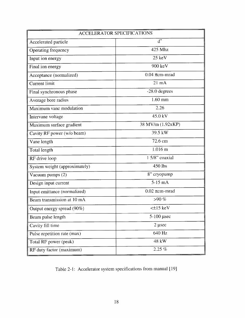
2.1. Accelerator Specifications
The starting point for any design of an accelerator based system must begin with
the accelerator itself. The accelerator chosen for this experiment was manufactured by
AccSys Technology, Inc. and is Model DL-1. It is a radio frequency quadropole (RFQ)
linear accelerator which accelerates deuterium particles (Table 2-1). The most critical
specifications that directly impact the design of the target system include the maximum
duty factor of 2.25%, final deuterium ion energy of 900 keV, and the divergence of the
emitted beam.
ACCELERATOR SPECIFICATIONS
Accelerated particle d+
Operating frequency 425 Mhz
Input ion energy 25 keV
Final ion energy 900 keV
Acceptance (normalized) 0.04 itcm-mrad
Current limit 21 mA
Final synchronous phase -28.0 degrees
Average bore radius 1.60 mm
Maximum vane modulation 2.26
Intervane voltage 45.0 kV
Maximum surface gradient 38 MV/m (1.92xKP)
Cavity RF power (w/o beam) 39.5 kW
Vane length 72.6 cm
Total length 1.016 m
RF drive loop 1 5/8" coaxial
System weight (approximately) 450 lbs
Vacuum pumps (2) 8" cryopump
Design input current 5-15 mA
Input emittance (normalized) 0.02 ncm-mrad
Beam transmission at 10 mA >90 %
Output energy spread (90%) <±15 keV
Beam pulse length 5-100 psec
Cavity fill time 2 gtsec
Pulse repetition rate (max) 640 Hz
Total RF power (peak) 48 kW
RF duty factor (maximum) 2.25 %
Table 2-1: Accelerator system specifications from manual [19]

The two main reactions used with a deuteron accelerator are the D-D reaction and
the D-T reaction. Since tritium is radioactive, special precautions must be taken at all
times during its handling. These extra precautions and added risk are not desirable
during these experiments and so the D-D interaction is the only practical choice. Once
the system is ready for full implementation, it may be desirable to switch to tritium gas in
the target chamber since the D-T reaction is more energetic (17.6 MeV for D-T, 3.27
MeV for D-D). This switch will have a negligible effect on the target system since
tritium and deuterium have similar transport characteristics but the safety precautions
necessary for handling tritium may preclude this.
The use of the D-D interaction will allow for the selection of specific neutron
energies to be emitted. The reaction has a Q of 3.26 MeV and is as follows:
21H + 21H ---> 32He + 'on (2.1)
From the kinetics of the interactions we can solve for the dependence of the exiting
neutron energy and get
mamTa.cos(0) + mambTacos)2 (m+ )"[m -Q m - m T
(2.2)
where:
ma = mass of deuteron Ta = energy of incoming deuteron
my = mass of helium Q = energy released, 3.26 MeV
mb = mass of neutron Tb = energy of outgoing neutron
0 = angle of outgoing neutron with respect to incoming deuteron.

The solution of equation 2.2 over a range of incoming deuteron energies and exiting
neutron angles is given in Figure 2-1. This clearly shows that neutron energy can be
chosen by fixing the incoming deuteron energy and the exiting angle. Unfortunately, s
the deuterons begin to scatter inside the target, ionizing losses will cause their energies to
decrease and begin to spread, thus spreading the final neutron energies. This effect is
dependent on the thickness of the target and will be greater in thicker targets [2].
1 2 3 4 5 6
Incoming Deuteron Energy (MeV)
7 8 9
Figure 2-1: Energies of neutron from D-D reaction.
2.2. Previous System Theory
The target system had already undergone two generations of designs before this
latest redesign effort began. The initial design attempted to implement a system of pipes
in which blocked flow occurred. Blocked flow is the condition where the gas attempts to
I I I I I I
600
300
900
1200
-- -- -- -------- -
1800
,,II

flow faster then the speed of sound but is prevented by the buildup of the pressure waves
inside the tubes.
The presence of blocked flow inside a tube is dependent on the geometry of the
tube, characteristics of the gas, and the pressure differential across the tube. For viscous
laminar flow in a tube, the critical exit pressure is given by
Pc d2-. 2.3 -- pp 1 (2.3)
where:
Pc = critical exit pressure p = inlet pressure
1 = length of tube d = diameter of tube [4].
The flow of air under these blocked conditions is given by
d3 p2_ ( pc2qc" 135.d--
1 2 (2.4)
where qc is given in millibar-liters per second [4]. If the flow in the tube is turbulent
rather then viscous (Reynolds number greater then 4000) then the critical pressure is
given by
4
4.51.p 2Pc \ 2-1
p d-p (2.5)
and the flow of air is given by
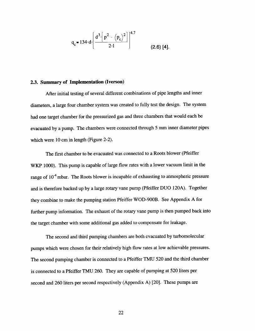
2-1 (2.6) [4].
2.3. Summary of Implementation (Iverson)
After initial testing of several different combinations of pipe lengths and inner
diameters, a large four chamber system was created to fully test the design. The system
had one target chamber for the pressurized gas and three chambers that would each be
evacuated by a pump. The chambers were connected through 5 mm inner diameter pipes
which were 10 cm in length (Figure 2-2).
The first chamber to be evacuated was connected to a Roots blower (Pfeiffer
WKP 1000). This pump is capable of large flow rates with a lower vacuum limit in the
range of 10-4 mbar. The Roots blower is incapable of exhausting to atmospheric pressure
and is therefore backed up by a large rotary vane pump (Pfeiffer DUO 120A). Together
they combine to make the pumping station Pfeiffer WOD-900B. See Appendix A for
further pump information. The exhaust of the rotary vane pump is then pumped back into
the target chamber with some additional gas added to compensate for leakage.
The second and third pumping chambers are both evacuated by turbomolecular
pumps which were chosen for their relatively high flow rates at low achievable pressures.
The second pumping chamber is connected to a Pfeiffer TMU 520 and the third chamber
is connected to a Pfeiffer TMU 260. They are capable of pumping at 520 liters per
second and 260 liters per second respectively (Appendix A) [20]. These pumps are

capable of reaching pressures below 105 mbar and both are backed by a single rotary
vane pump (Trivac D16). This backing pump is then exhausted to the room.
Rotated 90 degreesfor clarity
PumpStage 3
Pump TargetStage 1 Chamber
PumpStage PI-
Beam FLow
Figure 2-2: Initial design with only pipes.
While initial tests proved promising, it became clear upon implementation that
blocked flow was not achieved. The assumption that the pipes could be approximated as
long tubes (relative to their diameter) apparently was incorrect. The appropriate
assumption now appears to be treating the pipes as exit nozzles from one section to the
other [4]. This failure to achieve blocked flow resulted in a vastly increased flow
between chambers and greatly reduced the achievable pressure differential throughout the
system.

While one option to correct this would have been to elongate the tubes, this would
have required that the entire system be lengthened, which was not desirable and any
additions to the length would increase the difficulties of the beam optics design. Another
option was to have the connections between chambers open only during the pulse of the
accelerator. This is possible given that the accelerator has a 2.25% maximum duty cycle.
The implementation is made difficult by the high pulse repetition rate of up to 640 Hz. In
order to achieve such a high rate of opening and closing of the tubes, it was determined
that a system using rotating disks would be the best. As the disks rotate, holes in the
disks will line up with the tubes, giving a clear path for the beam to travel during the
pulse. The disks would then continue to rotate and thus close off the tubes as the holes
no longer line up. Since the beam width is fixed by the duty factor and pulse rate of the
accelerator, this establishes the timing for the beam. This timing can then be used to
determine the size of the holes in the disks and the overall relationship between the disks
and accelerator. This system was implemented with two rotating disks in the first
pumping chamber (Figure 2-3). In order to make room for the disks, the tube between
the target chamber and first pumping chamber had to be removed.

PumpStage 2
Beam Gas Flow
Figure 2-3: Cross section of previous system [4].
The attainable pressure differential in the system is now dependent on the
efficiency of the valves. This efficiency was determined by the leak rate of gas around
the disks while the disks were in the closed position (holes not lined up). While in the
closed position, the gas is able to flow in the space between the disk and the inside wall
of the chamber and can escape either around the edges of the disks or through the
aperture holes in the disks. To reduce this effect, the disks where machined to fit as
tightly as possible into the chamber, thus reducing the gap for the gas to flow between the
disks and the walls. Also, the disks were made with only two aperture holes, thus
preserving the balance while minimizing the number of paths for the gas to leak.
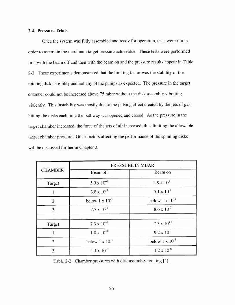
2.4. Pressure Trials
Once the system was fully assembled and ready for operation, tests were run in
order to ascertain the maximum target pressure achievable. These tests were performed
first with the beam off and then with the beam on and the pressure results appear in Table
2-2. These experiments demonstrated that the limiting factor was the stability of the
rotating disk assembly and not any of the pumps as expected. The pressure in the target
chamber could not be increased above 75 mbar without the disk assembly vibrating
violently. This instability was mostly due to the pulsing effect created by the jets of gas
hitting the disks each time the pathway was opened and closed. As the pressure in the
target chamber increased, the force of the jets of air increased, thus limiting the allowable
target chamber pressure. Other factors affecting the performance of the spinning disks
will be discussed further in Chapter 3.
PRESSURE IN MBARCHAMBER Beam off Beam on
Target 5.0 x 10+1 4.9 x 10+1
1 3.8 x 10-' 5.1 x 10⁻¹
2 below 1 x 10⁻³ below 1 x 10⁻³
3 7.7 x 10⁻⁷ 8.6 x 10⁻⁷
Target 7.3 x 10+1 7.5 x 10+1
1 1.0 x 10+0 9.2 x 10-'
2 below x 10-3 below 1 x 10⁻³
3 1.1 x 10⁻⁶ 1.2 x 10⁻⁶
Table 2-2: Chamber pressures with disk assembly rotating [4].

The same pressure measurements were run again but with the disk assembly no
longer rotating. This experiment showed what the next limiting factor in the system
would be if the disk assembly was sufficiently improved. As the pressure was increased,
the second stage pump (TMU 520) was the first to have problems and could not maintain
the required flow rate with a target pressure greater than 20 mbar. The pressure results
for this experiment appear in Table 2-3.
PRESSURE IN MBARCHAMBER Beam off Beam on
Target 2.0 x 10+1 2.0 x 10+'
1 5.7 x 10 5.3 x 10-'
2 5.4 x 10.3 6.7 x 10⁻³
3 3.3 x 10⁻⁷ 3.1 x 10⁻⁷
Table 2-3: Chamber pressures without disk assembly rotating [4].
During the previous experiment that utilized the rotating disks, the second stage
pump (TMU 520) drew less than half the maximum allowable current. This would
indicate that in this situation, the target pressure could be operated three to four times
higher before the second pump limited the system [4].

Chapter 3. Redesign Efforts
While the final work by Iverson failed to reach the desired pressure range in the
target chamber, it did manage to prove the validity of the idea of exit nozzles and
spinning disks. The largest improvements in the system will be gained by improving the
weakest part of the system, the design of the spinning disks. Other improvements in the
overall performance of the system will also be gained through modifying the pumping
system.
3.1. Mechanical Changes to System
As stated before, the instability of the disks at pressures above 75 mbar was
primarily caused by the pulsing effects of the jets of gas created each time the pathway
was opened and closed. While it is impossible to remove these jets, it is possible to
improve the structural characteristics of the spinning disk assembly to better resist these
effects.
The primary weakness in the spinning disk assembly is the structural support of
the shaft at either end. The existing design of the spinning disks has both disks attached
to a rotating 9.5 mm diameter shaft. The shaft is decreased in size at both ends to 3.2 mm
diameter and is supported by small bearings (Figure 3-1).
A magnetic clutch assembly controls the rotation of the shaft. In this assembly,
one side of the magnetic clutch is imbedded in the first spinning disk. On the other side
of the target chamber plate, the second half of the magnetic clutch assembly is mounted.
In this way, the second half is exposed to atmosphere and can be rotated by a standard
electric motor. While this method preserves the integrity of the plate and removes the
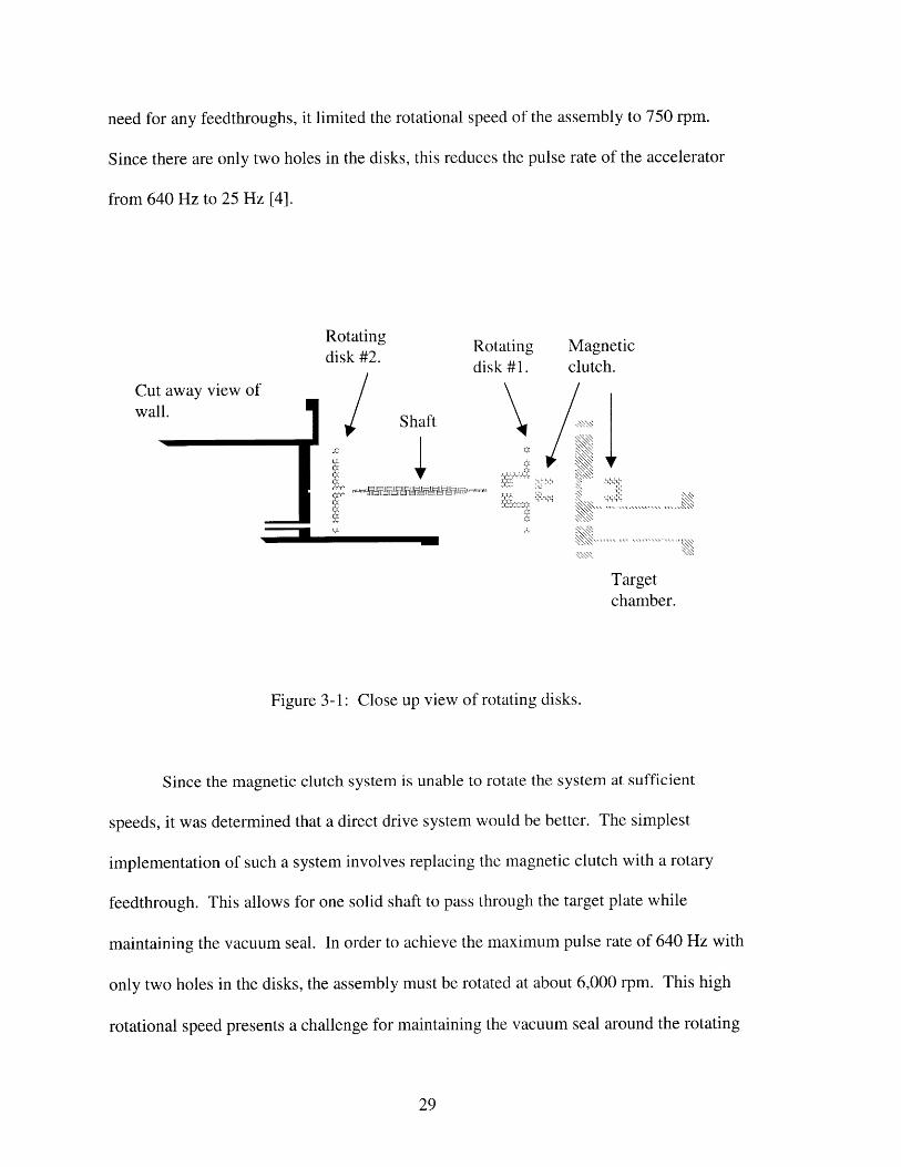
need for any feedthroughs, it limited the rotational speed of the assembly to 750 rpm.
Since there are only two holes in the disks, this reduces the pulse rate of the accelerator
from 640 Hz to 25 Hz [4].
Cut away view ofwall.
Rotatingdisk #2./
Rotating Magneticdisk #1. clutch.
IShaft
MI&XI/ m
" U-T"
Targetchamber.
Figure 3-1: Close up view of rotating disks.
Since the magnetic clutch system is unable to rotate the system at sufficient
speeds, it was determined that a direct drive system would be better. The simplest
implementation of such a system involves replacing the magnetic clutch with a rotary
feedthrough. This allows for one solid shaft to pass through the target plate while
maintaining the vacuum seal. In order to achieve the maximum pulse rate of 640 Hz with
only two holes in the disks, the assembly must be rotated at about 6,000 rpm. This high
rotational speed presents a challenge for maintaining the vacuum seal around the rotating
7777Wm

shaft in the feedthrough. This can be accomplished by using rotary seals which employ a
magnetic fluid to achieve a seal. A feedthrough capable of such high speeds was
procured from Ferrofluidics after some adaptations were performed to allow it to mate
with the rest of the system [21].
In order to stop the disk assembly from vibrating, the 9.5 mm diameter shaft and
support system were replaced. The shaft diameter was increased to 12.7 mm. This added
rigidity should reduce flexing in the shaft and dampen oscillations. With the increase of
the shaft and the addition of a feedthrough into the system, it was now possible to pass
the shaft through all three pumping chambers and then out into atmosphere. This allows
for the expansion of the two spinning disk system to include a third spinning disk in the
third pumping chamber. This additional disk will greatly reduce the flow of gas from the
second pumping chamber and improve the overall performance of the system (Figure 3-
2).

Rotated 90degreesfor clarity.
Ferrof uidic Pump Pump TargetFeed Stage 3 Stage 1 Chamber
Through
PumpStage 2
Beam IGas FLow
Figure 3-2: New disk assembly.
The two small 3.2 mm bearings that were supporting the original shaft have been
completely removed. The shaft is now supported at one end by the feedthrough and at
the other end by a 12.7 mm inner diameter bearing. No supports were included in the
inside walls of the chamber to avoid possible misalignment that would cause stress on the
shaft. Instead, exclusion seals from Ferrofluidics provide a stress free seal that prevents
leakage of gas around the shaft from one chamber to the next.
The thickness of the first disk was increased to 25.4 mm in order to limit the
leakage of gas around it. This increase creates a longer path that any gas must take as it
leaks around the edge of the plate. This longer path restricts the flow and should greatly
reduce leakage around the disk. In order to save weight, material is removed from the

side of the disk away from the wall. Unfortunately, the thickness of the second and third
disks could not be increased without obstructing the side pipes which connect to vacuum
pumps. As such, these two disks are made in a similar manner to the second disk in the
original design. See Appendix B for further information on system components.
At the high revolution speed of 6,000 rpm, balancing the disk assembly becomes
critical. While the disks have been designed and machined to maintain this balance,
further balancing is still needed. Once the entire system has been assembled, it will be
brought to an appropriate machine shop, rotated at high speeds, and professionally
balanced. This will remove any minor imperfections that would create problems at high
rates of revolutions.
3.2. Vacuum Pump Alterations
The initial Roots blower system utilized for the first pumping stage relied upon a
rotary vane pump (Pfeiffer DUO 120A) to provide backing pressure for the Roots blower
(Appendix A) [20]. This rotary vane pump contains oil in the pumping chamber which
was then introduced into the re-circulated deuteron gas. In order to prevent this the vane
pump was replaced with the UniDry 050 dry pump from Pfeiffer vacuum (Appendix A)
[20]. This pump is specifically designed for high volume flow rates and is ideal as a
backing pump for the Roots blower. The combination of the existing Roots blower and
the UniDry 050 pump allows for the same high volumetric flow rate as with the rotary
vane pump, but with totally dry pumping chambers.
A major design consideration of the windowless gas target system is the re-
circulation of all of the gas that leaks out of the target chamber. While this re-circulation
is critical in the first pumping stage, which has the highest flow rates, it is also beneficial
in the second and third stages. The current design of the system utilizes a rotary vane
pump (Trivac D 16A) as a backing pump for the turbomolecular pumps (Pfeiffer TMU
520 and TMU 260, Appendix A) in chambers two and three [20]. This rotary vane pump
exhausts the deuterium gas, which is expensive and explosive, into the room. The loss of
gas was acceptable at the low flow rates previously achieved, but may prove
unacceptable when the target pressure is raised higher. In order to re-circulate the gas,
the rotary vane pump will be replaced with a dry pump and connected back into the target
chamber. While another dry backing pump could be purchased, the simplest solution is
to utilize the same UniDry 050 for the Roots blower and both turbomolecular pumps.
This is possible because of the high flow rate capability of the UniDry 050, but the
increased load from the turbomolecular pumps will decrease the flow rate through the
Roots blower [22]. This decrease will be marginal since the turbomolecular pumps can
only pump a fraction of the capacity of the Roots blower.

Chapter 4. Plasma Arc Theory
Another promising method to support a large pressure differential has been
investigated by Herschovitch at Brookhaven National Laboratory. This method creates a
plasma arc between the high pressure target chamber and the first vacuum chamber.
Since the plasma is at very high temperatures, its pressure is equal to that of the target
chamber while its density is reduced by the ratio of arc to target temperature. The high
viscosity of such a system greatly limits flow through the plasma chamber and serves to
confine the gas inside the target chamber. Experiments by Herschovitch have resulted in
pressure differentials of close to four atmospheres with minimal pumping from the
vacuum chamber. The theory of the plasma porthole and the implementation of it into a
pumping system will be discussed in this and following chapters [23, 24, 25, 26].
4.1 Pressure and Density of Plasma Arc
The plasma arc to be used in this experiment will have a temperature ranging
from around 15000 K in the center to around 12000 K at the edges [23]. For a general
approximation, we can treat the plasma as an ideal gas and use the ideal gas equation
P-p.R.T (4.1)
with:
P = pressure T = temperature
p = density R = ideal gas constant.
Using this equation to compare the density of the plasma arc at 12000 K to the
density of the gas in the target chamber at 300 K, it is clear that the plasma is 40 times

less dense while at the same pressure. This low density at high pressures will be key in
allowing the plasma to support a large pressure differential while still allowing the
accelerated deuteron beam to pass through with minimal interactions.
4.2 Plasma Flow
The pressure differential that the plasma arc will be able to support is determined
by the amount of flow of the plasma. This flow is highly dependent on the physical
boundaries of the system as well as the physical characteristics of the plasma.
The system is composed of a two millimeter diameter, six centimeter long pipe.
As will be shown shortly, the flow of the plasma through the pipe can be approximated as
an ideal gas. For low flow through a small thin tube, the flow rate can be given by
7t-R4 dpQ-
8Q=7 dx/ (4.2)
where:
Q = flow rate R = ideal gas constant
4 = viscosity dp/dx = pressure difference in pipe.
It is clear from the above formula that in order to minimize the flow through the pipe
while maximizing the pressure differential, it is desirable to increase the viscosity as
much as possible [23, 24, 27].
While a complete derivation of the viscosity of the plasma arc would be beyond
the scope of this report, a more approximate derivation of the viscosity of gases will be
shown.
The type of interactions that are dominant in a gas or plasma system can be
estimated by the Knudsen number, Kn, for the system

Kn= (4.3)L
where:
S= the mean free path L = a characteristic length for the system.
A Knudsen number of much less than one implies a flow regime dominated by
intermolecular collisions. This type of flow is deemed viscous and is common at normal
pressures. A Knudsen number much greater than one implies a system where
intermolecular collisions are highly infrequent and the molecules act independent of each
other. This type flow is termed molecular flow and is present in high vacuum systems.
The third type of flow is when the Knudsen number is around one and this is termed
transition or slip flow conditions [28].
For this system, L is the diameter of the pipe, 2 mm. The mean free path can be
found from the simple relationship
- 1 (4.4)n-
where:
n = molecular density of the gas
a = cross section of intermolecular collisions.
For this system, n can be found from the ideal gas equation for a gas at 12000 K and a
pressure of 2 atm (4.1). A typical value for y is 10-19 m2 [28]. Hence, the mean free path
is 1.6*10 -5 m. This gives a Knudsen number of 0.007, which is much less than one, and
implies that the plasma present is dominated by intermolecular collisions. Due to this,
the plasma can be approximated as a high temperature ideal gas with little loss of
accuracy [29].

Treating the plasma as a high temperature gas simplifies the treatment of the
system. Typical fluid mechanics shows that viscosity is directly proportional to the
square root of temperature [28, 27].
As the plasma gas is raised in temperature and the intermolecular collisions
become less of a factor, this approximation begins to fail. Eventually, the plasma can be
treated as fully ionized, at which point the viscosity becomes directly proportional to
temperature [30]. It is important to note that this plasma is in the absence of any applied
magnetic field.
4.3 Focusing Effect
An added benefit gained from the use of the plasma window is a focusing effect
of the deuteron beam. As current flows in the plasma arc it creates a circular magnetic
field around the center of the plasma which results in a field in the 0 direction. As the
positively charged deuteron particles pass through the plasma they interact with the
magnetic field and feel a force towards the center of the tube which can be determined by
F=q.VxB(4.5)
where:
q = charge of the deuteron v = velocity
B = induced magnetic field.
This focusing effect on accelerated beams has been investigated as a replacement for
other beam optics [31, 32]. These "plasma lenses" are able to focus the beam in the x and
y direction simultaneously while other methods, such as permanent magnet quadropoles

(PMQs), can only focus the beam on one axis while increasing the beam on the other.
The amount of focusing achieved is highly dependent on the power inside the plasma arc
as well as the characteristics of the beam. Figure 4-1 shows the results from an
experiment in which a 5 MeV proton beam was focused by a plasma lens of varying
voltages [31].
a b c
Figure 4-1: 5 MeV proton beam size (4.5 cm without focusing) after
focusing with various plasma voltages (a. 4 kV, b. 7 kV, c. 9 kV) [31].

Chapter 5. Implementation of Plasma Arc
The creation of a stable plasma arc requires more than the application of high
voltage between a cathode and an anode. The plasma arc will follow the path of least
resistance which, in a gas, is the path of highest temperature. Due to this, the arc will
move around as the thermal layers of the gas move. In order to stop this, the temperature
variations in the gas must be well controlled throughout the process. These requirements
are met by the "Plasma Porthole" created by Hershcovitch. The design and
implementation of this device will be discussed in this chapter.
5.1 Plasma Porthole
The plasma porthole was designed to stabilize a plasma arc down the center of a
small cylinder. This was accomplished by stacking thin copper plates (5 mm thick) with
thin plates of boron-nitride (1.3 mm) in-between (Figure 5-1). Each of the plates had a
small two mm hole drilled in the center and once all the plates were stacked, it formed a
six cm long cylinder. Copper was chosen for its high heat conductance rate and overall
heat characteristics. The plates were individually cooled by a chilled water supply and
served to cool the gas on the outer edges of the cylinder. The outer cooling causes the
warmest part of the gas to be at the center of the cylinder at all times. This stabilizes the
thermal layers of the gas which in turn stabilizes the plasma arc.
A second criteria for creating a plasma arc is the isolation of the voltage potential
through the gas. Since the current will seek out the least resistance possible, this isolation
prevents the current from flowing through the structure instead of the gas. The boron-
nitride plates between the copper cooling plates serve to isolate the plates from ground as

well as from each other. Care has been taken to prevent the plasma from coming in
contact with the insulating plates to prevent them from melting. Each of the three
structural bolts that hold the system together are covered by plastic sleeves and use
plastic washers at the end to prevent them from creating a short. The three cathode
holders are likewise isolated from the rest of the system by plastic sleeves.

Gas targetchamber.
Cathodeassembly(x3).
Copper p1(thick).
Boron-nitride(thin).
Anodeplate.
Gas line in.
Low pressure side.Incoming beam.
Structuralbolt (x3).
11.4 mm
Figure 5-1: Cross section of plasma porthole [33].
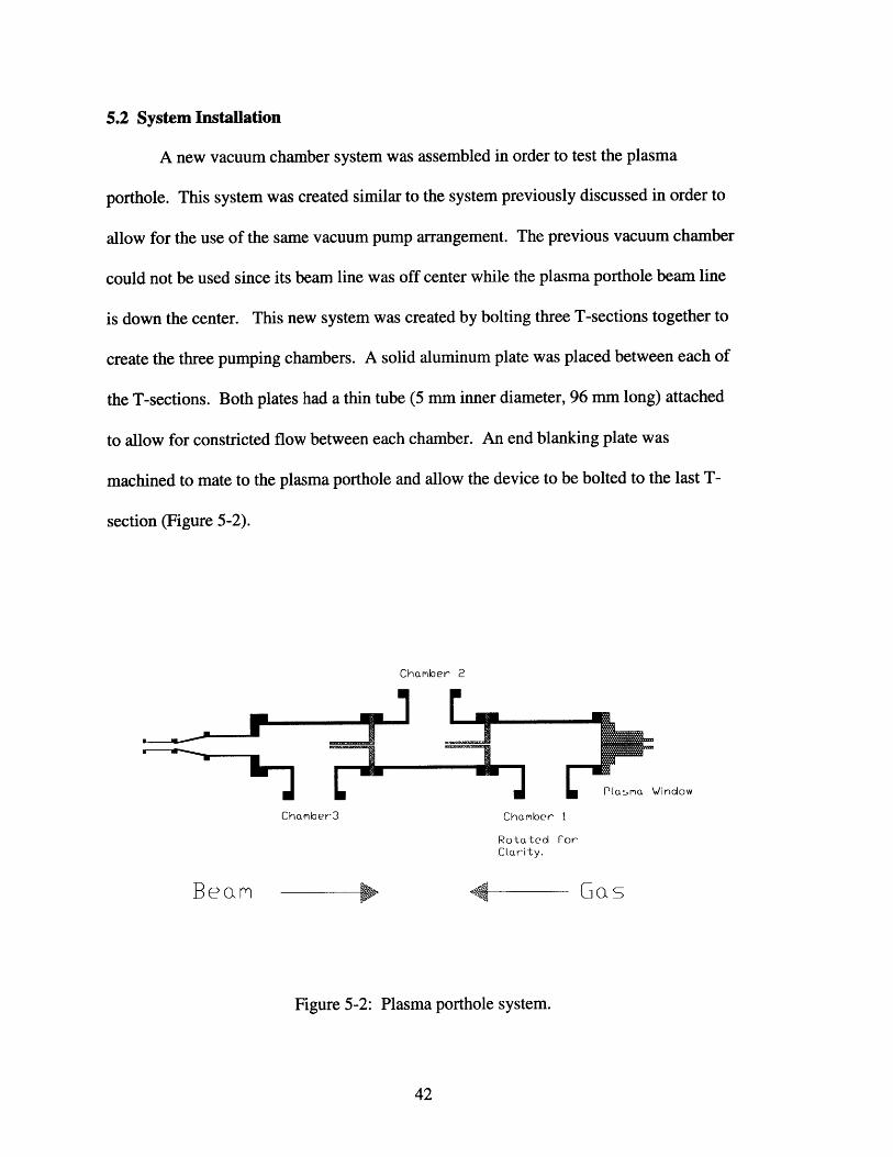
5.2 System Installation
A new vacuum chamber system was assembled in order to test the plasma
porthole. This system was created similar to the system previously discussed in order to
allow for the use of the same vacuum pump arrangement. The previous vacuum chamber
could not be used since its beam line was off center while the plasma porthole beam line
is down the center. This new system was created by bolting three T-sections together to
create the three pumping chambers. A solid aluminum plate was placed between each of
the T-sections. Both plates had a thin tube (5 mm inner diameter, 96 mm long) attached
to allow for constricted flow between each chamber. An end blanking plate was
machined to mate to the plasma porthole and allow the device to be bolted to the last T-
section (Figure 5-2).
Chamber 2
Plasma Window
Chamber3 Chamber 1
Rotated forClarity.
eam igure 5-2: Plasma porthole system.as
Figure 5-2: Plasma porthole system.

Once the plasma porthole was connected to the vacuum chambers, final
connections were made. The target chamber was screwed into the front of the porthole
and the necessary gas connections were made. A coarse and a fine valve were included
in the gas line in a parallel arrangement. The fine valve was used to control the gas flow
before the arc was created and then the coarse valve was used to raise the pressure
afterward. Chilled water lines were connected to the system to provide cooling for the
cathodes, copper plates, and anode plate. Finally, electrical lines were connected from
the power supply to each of the cathode holders while the ground line was connected to
the anode plate.
5.3 Expected Results
From discussions with Hershcovitch, we expected to achieve three atmospheres of
pressure in the target chamber while maintaining 10-4 torr in the first vacuum chamber
[25]. This pressure differential is dependent on the amount of energy that is inputted into
the system. With higher energy, the temperature of the plasma gas is raised, thus raising
the viscosity of the gas and decreasing the plasma flow. This can be clearly seen from
previous experiments by Hershcovitch [26]. Since the electrons in hydrogen gas are
more tightly bound than in argon, it is harder to create a plasma arc in hydrogen. This
requires that a higher voltage be applied to achieve the same results.
VOLTAGE (V) CURRENT (AMPS) POWER (KW) APRESSURE (ATM)193 50 9.7 3.1208 50 10.4 3.8158 50 7.9 1.3196 40 7.9 3.4203 50 10.2 3.5
Table 5-1: Pressure achieved at different power levels in argon [26].

Chapter 6. Applications
With the creation of a stable windowless target system, several of the previous
limitations on accelerators can be removed. These limitations on beam current, energy
focusing, and overall power output, have hampered many attempted accelerator
applications. These applications will now benefit greatly from the new windowless target
system.
6.1 Intense Fast Sources
With the removal of the limitations on the beam current and energy, it is now
possible to create high intensity fast neutrons. The high energy of the neutrons greatly
increases their range and allows for the imaging of larger objects. In a similar manner,
the high beam current increases the radiation reaching the detector and reduces the time
needed for recording data. This significant reduction in imaging time increases the
throughput time of the system that has previously served as a limiting factor in many
applications.
One program that will benefit greatly from both of these improvements is the
nuclear stockpile stewardship. This project requires an imaging technique that can detect
small defects in low-Z material that is surrounded by high-Z material in a nuclear device.
The goal is to capture a full tomographic image within a few hours while being able to
detect voids and other defects in the range of a cubic-mm. Previous experiments have
proven the feasibility of this project with neutrons of energies between 4 and 400 MeV.
These experiments drilled holes 4 to 12 mm in diameter in a 2.54 cm thick disk of LiD
and placed it between two blocks of uranium (Figure 6-1). Preliminary experiments have

shown that similar results can be achieved with lower energy neutrons between 10 and 15
MeV and about 1012/4ir n/sec/sr [34,31].
4 - 400 MeV phantom target assembly tungstenneutron beanm (side) (front) transmitted beam converter
O --
2.54 cm thick 5.00 cm thick wire-chamber
LiD disk uranium slabs particle detector
Figure 6-1: Proof of principal experiment for imaging low-Z
material between blocks of high-Z material [35].
6.2 Monoenergetic Sources
Without a physical boundary to slow the accelerated particles down, the spread of
neutron energies is greatly reduced. As shown previously, by choosing the reaction,
characteristics of the accelerated beam, and the angle at which the neutrons are removed,
it is possible to choose the neutron energy. This beam of tightly focused specific energy
neutrons can be used to improve many imaging and detection techniques.
An important application that could take advantage of the energy focusing is the
imaging of luggage for possible explosives. Studies have been conducted that pass
neutron beams through luggage and analyze the transmitted spectrum. The neutron
energies range from around 0.8 MeV at the lower end with an upper level between 4 and
8 MeV, depending on the experiment. Beams with such wide ranges of energies are

called "white" sources. The luggage is divided into pixels and the transmitted spectrum
is analyzed for each pixel. The densities of H, C, N, and O are calculated with
contributions from all other elements grouped into a fictitious element X. Since plastic
explosives have high concentrations of N and 0, the density information is used to
establish a probability of the presence of plastic explosives. An improvement to this
system can be gained by comparing this "white" neutron transmission spectrum to the
transmission spectrum from a focused, monoenergetic neutron beam with energies
between 4 and 5 MeV. As can be seen from Figure 6-2, the nitrogen cross-section is
much higher for neutrons of this energy. By comparing these two transmitted spectrums,
the difference will highlight the presence of nitrogen and greatly improve the accuracy of
its density calculation [36, 37, 38, 39].
4.,5 I I I
4.0
3.5.Q
00
1 2 3 4 5 6 7 8 9 10 11 12 13 14 155
Energy (eV) *10'2.00
1.5
1.0
1 2 3 4 5 6 7 8 9 10 1I 12 13 14 15
Energy (eV) "1°6
Figure 6-2: Total nitrogen cross-section versus
neutron energy [40].

A second application that would gain from the comparison of "white" neutron
transmission and monoenergetic neutron transmission is the search for dense carbon in
unprocessed ore. In this system, small amounts of dense carbon are being removed from
large amounts of ore and the system must be able to quickly distinguish and sort out the
ore that contains the carbon. The total neutron cross-section for carbon contains a peak
between 7 and 9 MeV (Figure 6-3) which can be used to identify it [18].
2 3 4 5 6 7 8
Energy9 10 11 12 13
(eV)
Figure 6-3: Total carbon cross-section versus
neutron energy [40]
Both of these applications will also benefit from the reduction in scanning time
that is gained from the increase in neutron flux as mentioned previously.
6
5
-C4
0Z; 3
02
I, I I I I I I I I I I I
I I I I I I I I I I I I
15*1o0

6.3. Accelerator-driven Transmutation of Waste (ATW)
Research has been conducted at Los Alamos National Laboratory to solve the
problem of nuclear waste disposal by "burning" the long lived actinides in sub-critical
assemblies. An accelerator is used to inject neutrons into the assembly which cause the
long lived actinides to fission during sub-critical nuclear chain reactions. Multiple sub-
critical assemblies are driven by a high energy proton accelerator that utilizes a 1000
MeV proton beam at 40 mA (40 MW) and a 100% duty cycle. The beam is split into
different assemblies and in each it passes through a window and then into a liquid
spalation target of lead or lead-bismuth eutectic. The liquid lead target also serves as a
coolant for the sub-critical assembly and the window (Figure 6-4 and Figure 6-5).
Removal of the physical window would allow for greater beam currents as well as a
vastly improved life span for the target system [41, 42, 43].

Proton
A TW Burner Beam
Typical Power:2000 MWt
Pump
Liquid LeadCoolant -
Heat Exchanger: tosteam-driven power production(up to 40% eff.)
Figure 6-4: ATW target system [41].
tersar
lmtrtlm ,. tltP -
Figure 6-5: Enlarged view of window system with
cooling flow from liquid target [41].

Chapter 7. Conclusions and Future Work
Two separate windowless gas target systems have been investigated during this
research. While the theory of both systems has been proven, neither one fully met the
design goals of several atmospheres in the target chamber during previous experiments.
Through the development achieved during this research, it is hoped that both systems will
improve greatly in attainable pressures. It is at this point that we must ask whether one
system is more advantageous than the other, and where should future efforts be invested.
7.1 Comparison
As shown in this report, the two systems differ vastly in their guiding principles.
The mechanical system created by Iverson relies upon low conductance nozzles and
rotating disks which open and close the beam pathway. The second system developed by
Hershcovitch relies instead on the high pressure, low flow characteristics of a plasma arc
along with low flow nozzles between chambers. This great difference in underlying
principles results in vast differences in implementation.
The first and most obvious difference between the mechanical and plasma system
is that the plasma system requires no moving parts. This removes a large degree of
difficulty in design for the plasma window. The mechanical system will need to be
precisely balanced to allow it to rotate at speeds that match the accelerators 640 Hz pulse
rate. This also introduces difficulties in timing the accelerator pulse to the alignment of
the holes. Finally, the added complication of high speeds components results in a greater
likelihood that a part will break, possibly catastrophically. With the removal of moving
components for the plasma system, all of these concerns are removed.

The addition of the plasma arc to the system adds different complications. First,
the cooling requirements for the plasma channel must be met at all times during
operation. Possible melting of the boron-nitride plates and the metal components could
occur if there is an interruption in the chilled water supply. Cooling must also be
provided for the first vacuum chamber to counteract the heat deposited from the small
flow of plasma into the chamber. Without this cooling the chamber will be heated above
acceptable limits within ten minutes [26]. The plasma window also requires a large
power supply to strike and sustain the arc. Such a large power supply could be unwanted
in some circumstances.
In the end, there are two final deciding factors that makes the performance of the
plasma arc more desirable than the performance of the mechanical system. First, the
plasma arc is designed to be operated steady state and allows for accelerator duty cycles
of up to 100%. The mechanical system however relies upon the fact that the accelerator
has a 2.25% duty cycle. Increases in the duty cycle would require that the holes in the
disks be increased to allow for longer pulses which would reduce the efficiency of the
disks and thereby reduce the efficiency of the overall system. The second deciding factor
in favor of the plasma system is its favorable focusing effect on the deuteron beam. Such
an effect is highly desirable in many applications and would reduce the need for other
focusing devices.
While it is clear that the plasma arc system is more desirable than the mechanical
system, it must be pointed out that the two systems are not mutually exclusive. It is
possible to combine the two systems when higher target pressures are desired. Such a

system would combine the drawbacks of each system but may also allow for pressures
which neither system could reach independently.
7.2 Future Work
This research has investigated and designed two separate windowless gas target
systems for future experimentation. Some final assembly is required on each system
before testing may begin but this should be easily accomplished. Once the systems are
complete, tests should be run first with argon gas and without the accelerator beam
running to allow for simple first approximation runs on each system. Once these are
complete and the systems are well characterized, they should be aligned properly with the
beam and the pressure tests should be recreated with deuterium gas. Depending on the
results achieved from these initial runs, the beam should then be activated and the
neutron flux should be measured. The maximum neutron flux will most likely be limited
by radiation protection concerns rather then by any system constraints.

Appendix A. Pump Information
The following pages contain information on the WOD 900 B, TMU 520, TMU260, and the UniDry 050. All of the information was taken from the Pfeiffer VacuumTechnology catalog [20].

Roots Vacuum Pumping Station WOD 900B.
Ordering number:Type designation:Price:
PPS42010WOD 900 Bon request
The compact, serial pumping station for all applications in the rough and mediumvacuum range.
Characteristics:Flange (in)Flange (out)Nominal pumping speedUltimate pressure: Total without gas ballast, smallerUltimate pressure: Total with gas ballast, smallerMains requirement: Voltage (selectable)Control cabinetVersion
WOD 900 B (50 Hz)
101
if~
DN 160 ISO-FDN 63 ISO-KF900 m3/h7.52-10-05 Torr7.52-10-05 Torr230/400 V, 50 HznoWith two stage backing pump
I 1 14
____ __ __.. ... ... ... ... __ ___ ___
14 V0:2p(m bar)
DN1 = DN 160 ISO-FDN2 = DN 63 ISO-KF
_~
' i l
A = 1280 mmC = 1330 mmE = 1045 mmG = 400 mm
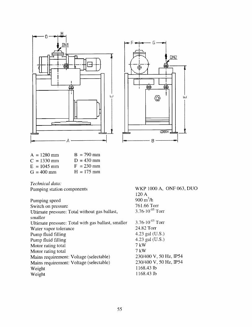
Technical data:Pumping station components
Pumping speedSwitch on pressureUltimate pressure: Total without gas ballast,smallerUltimate pressure: Total with gas ballast, smallerWater vapor tolerancePump fluid fillingPump fluid fillingMotor rating totalMotor rating totalMains requirement: Voltage (selectable)Mains requirement: Voltage (selectable)WeightWeight
WKP 1000 A, ONF 063, DUO120 A900 m3/h761.66 Torr3.76.10 -o05 Torr
3.76-10 -03 Torr24.82 Torr4.23 gal (U.S.)4.23 gal (U.S.)7 kW7 kW230/400 V, 50 Hz, IP54230/400 V, 50 Hz, IP541168.43 lb1168.43 lb
L B - --
B = 790D = 430F = 230H = 175
mmmmmmmm

Turbomolecular Drag Pump TMU 520.
Ordering number:Type designation:Price:
PMP02430TMU 52013 200.00 US
The turbo drag pump with the edge in pumping speeds.
Industries* Process Technology* Lamps etc.* Transportation* Scientific
Characteristics:Flange (in)Flange (out)Pumping speed: for N2Ultimate pressure with sinUltimate pressure with diaGas throughput for N2Fore vacuum max. for N2Sealing gas connection
gle stage rotary vane pumpphragm pump
DN 160 CF-FDN 25 ISO-KF500 1/s< 7.52.10-11 Torr< 7.52.10-11 Torr236.69 sccm12.03 Torrno

600
ta 500
400300
200
100
0
10o
DN1 = DN 160 CF-FDN2 = DN 25 ISO-KF
S,------
_f ,;:" - _. '' i
K-i
A = 224 mmC = 122 mmE = 170 mmG = 166 mmK =86mm
B = 115 mmD = 64 mmF = 127 mmH = 119 mm
® High vacuum connection( Venting connection
Air cooling
.v! Fore vacuum connection(i Power connection
- Water connection
10mbap(mbar)
TMU 520 M, DN 160

Technical data:Pumping speed: for N2
Pumping speed: for HePumping speed: for H2
Compression ratio for N2Compression ratio for HeCompression ratio for H2Gas throughput for N2
Gas throughput for HeGas throughput for H2
Ultimate pressure with single stage rotary vane pumpUltimate pressure with diaphragm pumpRecommended roughing pumpRotational speed +-2%Rotational speed: Stand-byRun-up time with TCP 600Cooling method, standardCooling water consumptionWeight
500 1/s500 1/s480 1/s1.00-10125.00.10075.00.1006236.69 sccm414.21 sccm532.55 sccm< 7.52.10 -1 Torr< 7.52.10-10 TorrMD 4T, DUO 010 M, UniDry50000 rpm33000 rpm5 minwater15 1/h27.56 lb

Turbomolecular Drag Pump TMU 260.
Ordering number:Type designation:Price:
PMP02135TMU 2606 610.00 US
The turbo drag pump designed for a wide field of applications in industry and research.
Industries* Process Technology* Lamps etc.* Transportation* Scientific* Analytical
Characteristics:Flange (in)Flange (out)Pumping speed: for N2Ultimate pressure with single stage rotary vane pumpUltimate pressure with diaphragm pumpGas throughput for N2
Fore vacuum max. for N2
Sealing gas connection
DN 100 CF-FDN 25 ISO-KF210 1/s< 7.52.10 -11 Torr< 7.52-10 -09 Torr147.93 sccm7.52 Torrno

TMU 260, DN 100
250
200
150
100
50
0
10 10-4
DN1 = DN 100 CF-FDN2 = DN 25 ISO-KF
194.5 mm82.0 mm135.0 mm128.5 mm86.0 mm
= 115.0 mm= 64.0 mm= 127.0 mm= 95.0 mm
High vacuum connectionFore vacuum connectionVenting connectionPower connectionAir coolingWater connection
10-2 10-1
p(mbar)
(V+

Technical data:Pumping speed: for N2
Pumping speed: for HePumping speed: for H2Compression ratio for N2
Compression ratio for HeCompression ratio for H2
Gas throughput for N2
Gas throughput for HeGas throughput for H2Ultimate pressure with single stage rotary vane pumpUltimate pressure with diaphragm pumpRecommended roughing pumpRotational speed +-2%Rotational speed: Stand-byRun-up time with TCP 380Cooling method, standardCooling water consumptionWeight
210 1/s220 1/s180 1/s1.00-10093.00.100'13000147.93 sccm147.93 sccm118.35 sccm< 7.52.10 -1 Torr< 7.52-10 -09 TorrMZ 2T, UNO 005 A60000 rpm40000 rpm1.5 minwater15 1/h19.85 lb

UniDryTM 050
Ordering number:Type designation:Price:
PKT1 1101UniDryTM 050-4on request
Standards:- casing: nodular cast iron GGG 40.3- casing seals: Viton- radial shaft seals: PTFE- operating fluid for gear box: F5 (filling not included)
Characteristics:Flange (out)VersionUltimate pressure, smallerMains requirement: Voltage (range)Pumping speed
DN 25 ISO-KFwith standard motor3.76.10 -02 Torr230/400 V, 50 Hz50 m3/h

Technical data:Number of stagesPumping speed at 50 HzPumping speed at 60 HzUltimate pressureIntake pressure max.Leak rateMotor ratingPower consumptionRotational speed at 50 HzRotational speed at 60 HzCooling water consumption max.Cooling water consumption at intake pressureCooling water temperature max.Cooling water pressureCooling water connection, female threadCooling water connectionNoise level with connected exhaust lineLubricant amount in gearAmbient temperatureWeight: without motorWeight: with motor
4 pcs50 m3/h60 m3/h< 3.76.10-02 Torr751.88 Torr5.92 sccm3 kW1.3 W3000 rpm3600 rpm3 1/h25 1/h25 oC2-10 barDIN ISO 228 G 1/2"0.48 inch< 68 dB (A)8.45-10-02 gal (U.S.)5-40 oC253.53 lb297.62 lb
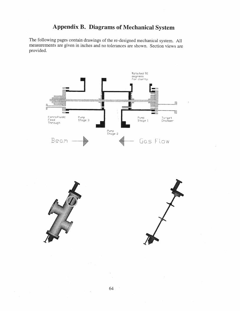
Appendix B. Diagrams of Mechanical System
The following pages contain drawings of the re-designed mechanical system. Allmeasurements are given in inches and no tolerances are shown. Section views areprovided.
Rotated 90degreesfor clarity.
PumpStage 2
Gas FowB(?am 0

Vacuum Chamber
20.81
L
6,47
4.66
6.42
0 wo
awe~
I
4.00
_ 1
.41.50 V
--5.63
0 _L _.50
5.75
-_L _,50
8,44
i~~

Disk I
1-03,75
0 C2 .5 0
0100
S 1,00
025- 1,88 -- ,
id i
0,
-I
I1IF
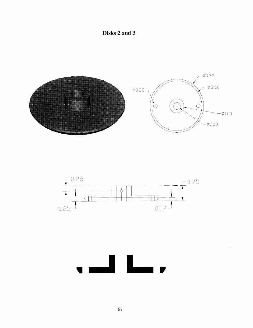
Disks 2 and 3
,-0375
, 03,5000,28
01 17_1
075
L
I -J L-M r
01,00
1"'"

Rotary Feedthrough from Ferrofluidics
1,32
3 I
3,75
0.78 -
0,25
05,97
0 09
0I I

Target Chamber
0.75
1,50-]
/-6.00
Ili I
4 38
II L I I . . . . . .

Appendix C. Diagram of Plasma Window System
The following pages contain drawings of the Plasma Porthole system. All measurementsare given in inches except when stated, and no tolerances are shown. Section views areprovided.
C
Chamnber3
amber 2
rirmn
Chamber
Pl sm Window
Rotated forClDrity
Pee aM
r
G, 0s

Vacuum Chamber
4350 1.76
4396 -

Rotated 90 Deg.for clarity.
06.0004,00
5 31
I I

Plates and Low Flow Pipes
0, 50
06 00
00 ,0
R0 PO
4,28

Plasma Window
Gas targetchamber.
Cathodeassembly(x3).
Copper p.(thick).
Boron-nitride(thin).
Anodeplate.
Gas line in.
Low pressure side.
Structuralbolt (x3).
11.4 mm
tIncoming beam.
References
1. Turner, James E. Atoms, Radiation, and Radiation Protection. McGRAW-Hill, Inc.
New York, 1992. Pp. 135-137.
2. Knoll, Glenn F. Radiation Detection and Measurement. Second Edition John Wiley
and Sons, New York, 1989. Pp. 20-27.
3. Drosg, M. "Monoenergetic Neutrons in the Energy Range From 100 eV to 200 MeVFrom Two-Body Reactions With the Hydrogen Nuclei." Neutrons in Research andIndustry. Vol. 2867, pp. 490-500, June 1996.
4. Iverson, Erik B. Windowless Gas Targets for Neutron Production Doctor of
Philosophy Thesis. Massachusetts Institute of Technology. February 1997.
5. Carpenter and Yellon. Meth. Exp. Phys. Vol. 23, pp. 99-196, 1986.
6. Peto and Replenik. "High-Intensity 14-MeV Deuterium-Tritium Neutron Generators:Present Achievements and Future Potential." Nuclear Science and Engineering. Vol.
106, pp. 219-227, 1990.
7. Booth, Davis, Hanson et all. "Rotating Target Neutron Generations." NuclearInstruments and Methods. Vol. 145, pp. 25-39, 1977.
8. Heikkinen, Logan, and Davis. "Rotating Target 14-MeV Neutron Generators."Nuclear Science and Engineering. Vol. 106, pp. 228-233, 1990.
9. Burke, Holmes, Johnson, Mann, and Miles. "SUPER-FMIT, an Accelerator BasedNeturon Source for Fusion Components Irradiation Testing." Nuclear Instruments and
Methods in Physics Research B. Vol. 10/11, pp. 483-486, 1985.
10. Carlson, David John. "Performance of a High-Pressure, High-Beam-Current GasTarget" Nuclear Instruments and Methods. Vol. 110, pp. 541-543 1973.
11. Mostafa. "Development and Performance of a High-Current Tritium Gas Target"Nuvlear Instruments and Methods. Vol 125, pp. 493-496, 1975.
12. Cramer and Cranberg. "Gas Target for Production of Monoenergetic Neutrons."Nuclear Instruments and Methods. Vol. 93, pp. 405-407, 1971.
13. Meadows, Smith and Winkler. "A High-Current Deuterium Gas Target For NeutronNuclear Data Research." Nuclear Instruments and Methods. Vol. 176, pp. 439-442,1980.

14. Haight and Garibaldi. "A Rotating Gas Cell for High-Intensity MonoenergeticNeutron Production." Nuclear Science and Engineering. Vol. 106, pp. 296-298, 1990.
15. Deleeuw, Haasz, Stangeby. "Canadian Gas Target Neutron Generator Research."Nuclear Instruments and Methods. Vol. 145, pp. 119-125, 1977.
16. Chenevert, Deluca, Kelsey, Torti. "A Tritium Gas Target as an Intense Source of 14
MeV Neutrons." Nuclear Instruments and Methods. Vol. 145, pp. 149-155, 1977.
17. Armstrong, Emigh, Meier, Meyer, and Schneider. "A 14 MeV Intense NeutronSource Facility." Nuclear Instruments and Methods. Vol. 145, pp. 127-148, 1977.
18. J.Watterson, Schonland Research Centre for Nuclear Sciences of the University ofWitwatersrand, Johannesburg, private communications.
19. Operation manual for Model DL-1 LINAC Neutron Generator System. AccSys
Technology, Inc. Pleasanton CA, October 1994.
20. Vacuum Technology 1997 Catalog from Pfeiffer Vacuum. Nashua, NH 1997.
21. Rick Michaud and Jim Fraser at Ferrofluidics, private communications.
22. Mark Clement from Pfieffer Vacuum, private communications.
23. Hershcovitch, Ady. "High-pressure arcs as vacuum-atmosphere interface and plasmalens for nonvacuum electron beam welding machines, electron beam melting, andnonvacuum ion material modification." Journal of Applied Physics. Vol. 78 (9),November, 1995
24. Herscovith, Ady. "A Plasma Window for Transmission of Particle Beams andRadiation from Vacuum to Atmosphere for Various Applications." Accepted forpublication.
25. Ady Hershcovitch from Brookhaven National Laboratory, private communications.
26. Data from Ady Hershcovitch, Brookhaven National Laboratory, privatecommunications.
27. Fox and McDonald. Introduction to Fluid Mechanics. Fourth Edition. John Wiley
& Sons, Inc. New York, 1992.
28. Gombosi, Tamas I. Gaskinetic Theory. Cambridge University Press, Great Britain,1994.
29. Kim Molvig at MIT, private communications.

30. Leontovich, Acad., Reviews of Plasma Physics, Volume 1. Consultants Bureau, New
York, 1969.
31. Belan et al. "Experiments on 5 MeV Proton Beam Focusing by Plasma Lens."Review of Scientific Instruments. Vol. 69, Number 2, pp. 1110-1112, February 1998.
32. Goncharov, Litovko, Onishchenko, Zadorozhny. "On 2D Electron Cloud Dynamicsin High-Current Plasma Lens for Ion Beam Focusing." Beam Stability and NonlinearDynamics. The American Institute of Physics, 1997.
33. Cross section supplied by Peter Stefan from Brookhaven National Laboratory.
34. Hall, Dietrich, Logan. "Development of High-Energy Neutron Radiography."Unpublished.
35. Dietrich, Hall, Logan. "Conceptual Design for a Neutron Imaging System for ThickTarget Analysis Operating in the 10-15 MeV Energy Range." Application of
Accelerators in Research and Industry. AIP Press, New York, 1997.
36. Overley et al. "Results of Tests for Explosives in Luggage From Fast-Neutron Time-
of-Flight Transmission Measurements." Neutrons in Research and Industry. Vol. 2867,pp. 219-222, June 1996.
37. Miller, Staagen, Gibson, Krauss. "Contraband Identification in Sealed Conatiners
Using Neutron Transmission." Neutrons in Research and Industry. Vol. 2867, pp. 215-
218, June 1996.
38.. Lefevre et al. "Using a Fast-Neutron Spectrometer System to Candle Luggage for
Hidden Explosives." Neutrons in Research and Industry. Vol. 2867, pp. 206-210, June
1996.
39. Chmelik et al. "Analysis of Blind Tests for Explosives in Luggage Through Fast-Neutron Transmission Spectroscopy." Unpublished. January 1997.
40. "Nuclear Data Viewer." Las Alamos National Laboratory. Viewed April 28, 1998.http://t2.lanl.gov/data/ndviewer.html.
41. Browne, Venneri, Li, Williamson. "Accelerator-Driven Transmutation of Waste."Los Alamos National Laboratory, un-published.
42. MIT ATW Technical Review, January 15-16, 1998.
43. M. Kazimi from MIT, private discussion.


![Competitive Target Advertising and Consumer Data Sharing · target advertising spending is projected to exceed $2.6 billion in 2014 [17]. investigation by the Wall Street Journal](https://static.fdocuments.in/doc/165x107/609c87261824582e15762910/competitive-target-advertising-and-consumer-data-sharing-target-advertising-spending.jpg)


