Investigation of the piezoelectric thimble tactile device ... · Investigation of the piezoelectric...
9
Acta of Bioengineering and Biomechanics Original paper Vol. 16, No. 3, 2014 DOI: 10.5277/abb140316 Investigation of the piezoelectric thimble tactile device operating modes RAMUTIS BANSEVICIUS 1 , EGIDIJUS DRAGASIUS 2 , VYTAUTAS GRIGAS 3 *, VYTAUTAS JURENAS 1 , DARIUS MAZEIKA 1 , ARUNAS ZVIRONAS 1 1 Institute of Mechatronics, Kaunas University of Technology, Kaunas, Lithuania. 2 Department of Production Engineering, Kaunas University of Technology, Kaunas, Lithuania. 3 Department of Mechanical Engineering, Kaunas University of Technology, Kaunas, Lithuania. A multifunctional device to transfer graphical or text information for blind or visually impaired is presented. The prototype using tactile perception has been designed where information displayed on the screen of electronic device (mobile phone, PC) is transferred by oscillating needle, touching the fingertip. Having the aim to define optimal parameters of the fingertip excitation by needle, the computa- tional analysis of different excitation modes has been carried out. A 3D solid computational finite element model of the skin segment, comprising four main fingertip skin layers (stratum corneum, epidermis, dermis and hypodermis) was built by using ANSYS Workbench FEA software. Harmonic analysis of its stress–strain state under excitation with different frequency (up to 10000 Hz) and harmonic force (0.01 N), acting outer stratum corneum layer in normal direction at one, two or three points has been performed. The influence of the mode of dynamic loading of skin was evaluated (in terms of the tactile signal level) on the basis of the normal and shear elastic strain in dermis, where mechanoreceptors are placed. It is shown that the tactile perception of information, delivered by three vibrating pins, may be influenced by configuration of excitation points (their number and phase of loading) and the frequency of excitation. Key words: tactile sensation, skin strain, harmonic excitation, finite element analysis 1. Introduction A lot of various applications exist today for blind and visually impaired: acoustic signal generators and special ground markers near road (zebra crossing), special ground markers near dangerous spaces, Braille texts and special marks (raised printing) on the banknotes, blind people sticks, etc. Furthermore, there is an increasing need to ensure blind or visually im- paired to be able to use modern technologies: televi- sion, computers, mobile phones and a lot of other devices, which help share information and make life more comfortable. First generation devices, helping to transfer information for blind people, were inconven- ient: they were big and clumsy, uncomfortable and not mobile. In addition, they were mostly dedicated to transfer only textual information. So to ensure their up-to-date functionality (size and mass parameters, simplicity, universality, etc.), the attempts to create more sophisticated equipment started. For example, a novel computer mouse was designed and patented [1] and its testing started [2], [3], but it was dedicated to computers controlled by mouse. Such systems are not suitable for compact modern devices as smartphones, PDA’s, etc., where even more compact and light devices should be employed. Again, they often may be materialized only by employment of modern technologies, for example, piezoelectric mate- rials. Piezoelectric actuators are widely used in differ- ent fields of modern engineering, from microscopes to systems for positioning objects with extreme accuracy. ______________________________ * Corresponding author: Vytautas Grigas, DepartmentofMechanicalEngineering, Kaunas UniversityofTechnology, Studentų str. 56-344, LT-51424 Kaunas, Lithuania. Tel: +370-37-204796, e-mail: [email protected] Received: February 6th, 2014 Accepted for publication: March 18th, 2014
Transcript of Investigation of the piezoelectric thimble tactile device ... · Investigation of the piezoelectric...

Acta of Bioengineering and Biomechanics Original paperVol. 16, No. 3, 2014 DOI: 10.5277/abb140316
Investigation of the piezoelectric thimble tactiledevice operating modes
RAMUTIS BANSEVICIUS1, EGIDIJUS DRAGASIUS2, VYTAUTAS GRIGAS3*,VYTAUTAS JURENAS1, DARIUS MAZEIKA1, ARUNAS ZVIRONAS1
1 Institute of Mechatronics, Kaunas University of Technology, Kaunas, Lithuania.2 Department of Production Engineering, Kaunas University of Technology, Kaunas, Lithuania.3 Department of Mechanical Engineering, Kaunas University of Technology, Kaunas, Lithuania.
A multifunctional device to transfer graphical or text information for blind or visually impaired is presented. The prototype usingtactile perception has been designed where information displayed on the screen of electronic device (mobile phone, PC) is transferred byoscillating needle, touching the fingertip. Having the aim to define optimal parameters of the fingertip excitation by needle, the computa-tional analysis of different excitation modes has been carried out. A 3D solid computational finite element model of the skin segment,comprising four main fingertip skin layers (stratum corneum, epidermis, dermis and hypodermis) was built by using ANSYS WorkbenchFEA software. Harmonic analysis of its stress–strain state under excitation with different frequency (up to 10000 Hz) and harmonic force(0.01 N), acting outer stratum corneum layer in normal direction at one, two or three points has been performed. The influence of themode of dynamic loading of skin was evaluated (in terms of the tactile signal level) on the basis of the normal and shear elastic strain indermis, where mechanoreceptors are placed. It is shown that the tactile perception of information, delivered by three vibrating pins, maybe influenced by configuration of excitation points (their number and phase of loading) and the frequency of excitation.
Key words: tactile sensation, skin strain, harmonic excitation, finite element analysis
1. Introduction
A lot of various applications exist today for blindand visually impaired: acoustic signal generators andspecial ground markers near road (zebra crossing),special ground markers near dangerous spaces, Brailletexts and special marks (raised printing) on thebanknotes, blind people sticks, etc. Furthermore, thereis an increasing need to ensure blind or visually im-paired to be able to use modern technologies: televi-sion, computers, mobile phones and a lot of otherdevices, which help share information and make lifemore comfortable. First generation devices, helping totransfer information for blind people, were inconven-ient: they were big and clumsy, uncomfortable and not
mobile. In addition, they were mostly dedicated totransfer only textual information. So to ensure theirup-to-date functionality (size and mass parameters,simplicity, universality, etc.), the attempts to createmore sophisticated equipment started. For example,a novel computer mouse was designed and patented[1] and its testing started [2], [3], but it was dedicatedto computers controlled by mouse.
Such systems are not suitable for compact moderndevices as smartphones, PDA’s, etc., where even morecompact and light devices should be employed. Again,they often may be materialized only by employment ofmodern technologies, for example, piezoelectric mate-rials. Piezoelectric actuators are widely used in differ-ent fields of modern engineering, from microscopes tosystems for positioning objects with extreme accuracy.
______________________________
* Corresponding author: Vytautas Grigas, DepartmentofMechanicalEngineering, Kaunas UniversityofTechnology, Studentų str.56-344, LT-51424 Kaunas, Lithuania. Tel: +370-37-204796, e-mail: [email protected]
Received: February 6th, 2014Accepted for publication: March 18th, 2014

R. BANSEVICIUS et al.136
A lot of such various purpose devices were developedin Kaunas University of Technology, including multi-functional tactile devices to convey graphical or textinformation for blind person [4].
The piezoelectric thimble under research consistsof piezoelectric disk actuator with a tactile pin – nee-dle in its center, assembled into a hollow disk shapedbody (Fig. 1a, b). It can be positioned on a blind per-son’s fingertip with the help of the rubber ring, so thatthe skin is always in contact with the needle (Fig. 1c).The information about the environment (for example,taken from PC or phone screen) can be transmitted byoscillating needle, which affects the fingertip skin.
The oscillations of the needle in normal directionto the skin surface are excited by piezoelectric actua-tor, connected to signal generator controlled by proc-essor, responding to the information displayed on thescreen of the device in the zone where the finger withthimble touches it. Because of a huge variety of thetypes of information, displayed on the screen of thedevice (text, graphics, color, etc.) a lot of regimes offingertip skin excitation should be used to ensurefunctionality of the device. Thus the computationalresearch of the fingertip skin–actuator pin interactionhas been initiated having the aim to verify the influ-ence of the mode of dynamic loading (frequency ofexcitation and the number of pins actuated in differentphases) on the tactile signal level, which is evaluatedby the intensity of normal and shear elastic strain indermis, where mechanoreceptors sensing normal andshear loading of the skin are placed.
2 Materials and method
With the aim to define optimal parameters of thefingertip excitation by needle (frequency of excita-tion, number and combination of active needles,etc.), a numerical simulation of piezoelectric thimble
needle–fingertip skin dynamic interaction at differentexcitation modes has been carried out.
Human skin is a multi-layered structure consistingof layers of epidermis, dermis and hypodermis (Fig. 2,[5]–[8]), having quite different material properties,with mechanoreceptors reacting to the tactile signals,affecting it. It is considered that mechanoreceptorsreact to the normal and shear deformations (strain),arising in skin around them. Meissner receptors (lo-cated at the junction of dermis and epidermis) sensethe normal loading, and Ruffini receptors (located inthe midst-top layers of dermis) are responsible for theshear sensing [7], [9]. Thus the response to a givenstimulus depends on the mechanical properties of theskin and parameters of excitation.
Fig. 2. Human skin structure
The proposed tactile device for modeling requiressome specific data, namely – about the reaction of thefingertip skin to vibrational excitation of its outerlayer (stratum corneum) surface. In the case describedthe configuration (number and location) of the opera-tor’s fingertip excitation points and the frequency ofthe excitation have had to be evaluated.
Two types of problems were solved during nu-merical investigation of fingertip skin:
(a) (b) (c)
Fig. 1. Piezoelectric tactile device: (a) photo, (b) cross section scheme, (c) 3D model.1 – body, 2 – needle, 3 – piezoelectric disc actuator, 4 – PC screen, 5 – finger, 6 – rubber ring [1]

Investigation of the piezoelectric thimble tactile device operating modes 137
• static structural analysis of the skin affected byreference force (serves for proving the correctnessof computational model);
• dynamic analysis of the skin segment – harmonicresponse analysis showing the strain state of theskin, arising under different modes of the har-monic excitation).The computational finite element model of the
skin was built and the investigation was performed bythe finite element analysis system ANSYS Work-bench 14.0. The simplified 3D solid geometricalmodel of the human finger skin segment (15 mmlength, 10 mm width, 6.0 mm thickness) was created(Fig. 3) with no external and internal, interlayer,ridges [6]. It consists of four rectangular parallelepi-ped shaped layers: total 0.2 mm thick epidermis layer(including 0.015 mm thick stratum corneum (external,tectorial) layer), 1.3 mm dermis and 4.5 mm upper,hypodermis (or subcutaneous tissue) layer. Three cir-cle shaped areas of 1.0 mm in diameter (one in themiddle of the lower surface and two at a 2 mm dis-tance from it along the longer side of the model) forapplying excitation were demarcated. It should benoted that the eventual size of the model, used forcomputations was defined after several attempts withsmaller models, which gave quite unstable results.The measurements of skin segment were increasedinsomuch that the results of computations becomepractically independent of the size of model.
Fig. 3. Geometric model of the skin segment
On the basis of geometrical model two computa-tional finite element models were built, representingone half of geometric model described above (eachconsisting of approximately 15000 tetrahedral (8-NodeStructural Solid) SOLID186 type finite elements(~40000 nodes) having size from 0.05 to 1 mm (de-pending on layer thickness, Fig. 4). Mechanical prop-erties of the appropriate skin layers [6]–[8] are listedin Table 1. For both static and harmonic responseanalysis, a linear elastic description of material prop-erties of skin layers was used because of very small
excitation signal level. In both cases the same bound-ary conditions (fixation) were used. Hypodermis layerwas fixed immovably (“Fixed Support” boundary con-dition, restraining all degrees of freedom of nodes), andthe side plain surfaces of all 4 layers, lying on thesymmetry plane of the model, were restrained by us-ing “Frictionless support” boundary condition. It al-lowed movement of nodes only in the symmetryplane, therewith allowing deformations of the wholemodel only in direction normal to the skin surface. Inthis way the presence of the same material at the otherside of the symmetry plane was simulated, thus givingadequate results of computation employing smallermodel and simplifying representation of the results ofcomputations.
Fig. 4. Finite element model of the skin segment
Computational model for the static structuralanalysis of the skin, “indented” by a 1 mm diameterround cross-section pin, was supplied by static force,acting the middle semi-circular area at the bottomsurface of stratum corneum layer of the model at nor-mal direction (Fig. 5).
Six computational models for the dynamic har-monic analysis were built, differing in the number,location and phase of excitation force of the same sizeand frequency, corresponding to the following typesof excitation of the fingertip skin by three tactile de-vice pins (Fig. 5). A three number coding system is usedfor identifying the type of excitation, where the “0”means the absence of excitation on the correspondingpin, “1” – normal phase excitation, and “–1” – 180°phase (inverse direction) excitation:1. Single pin (excitation applied to semi-circular area
at the center of the model) (code 010);2. Two adjacent pins (center and the left semi-
circular areas) synchronically (code 110);3. Three adjacent pins (all three semi-circular areas)
synchronically (code 111);4. Two outermost pins (both outermost semi-circular
areas) synchronically (code 101);

R. BANSEVICIUS et al.138
5. All three pins (all three semi-circular areas), butthe middle one with a 180° phase (inverse direc-tion) (code 1-11);
6. Two outermost pins (both outermost semi-circularareas), but the right one with a 180° phase (inversedirection) with regard to left one (code 10-1).
3. Results of computations
A linear static structural analysis of the fingertip skinaffected by static force, acting in normal direction, hasbeen performed considering the fact that a human beingsenses 0.1–0.2 mm skin movement on the finger surface[10]. Thus the size of force, inducing such a deformationof the skin surface, had to be established as well as thelevel of shear and normal strain, induced in dermis layer,containing Ruffini and Meissner receptors. The simplevariational solution showed that the 0.01 N size forceensures situation mentioned above (0.2 mm displace-ment of fingertip skin surface) (Fig. 6). The shape and
the depth of indentation are quite similar to the resultsobservable by simple experiments, thus validating thecomputational model. Maximum level of normal (verti-cal, Y direction) strain in the dermis reaches 0.1726, andthe maximum shear strain (horizontal, XZ plane)– 0.0535 (both – on the bottom surface of dermis layerdirectly above the indenter). Taking into account thatincrement of intensity of excitation force will lead toenlargement of size and correspondingly – power con-sumption of the piezoelectric thimble, namely this sizeof excitation force was used for further investigation.
The evaluation of the influence of regimes of skinexcitation by pins upon the fingertip skin tactile per-ception is performed by means of comparative har-monic dynamic analysis of the stress-strain state of themodel, representing fingertip skin segment, effectedby harmonically varying force (amplitude 0.01 N andfrequency up to 10000 Hz, with a step of 250 Hz),acting at the zones of location of three pins of tactiledevice. Damping during dynamic analysis was speci-fied as “Constant (modal) Damping Ratio”, equalto 0.3 [7]. The magnitude and character of normal and
Fig. 5. Computational model of skin segment for static and dynamic (harmonic) structural analysis
Fig. 6. Distribution of total deformations (displacements) of skin segment under 0.01 N static load in the center pin location
Investigation of the piezoelectric thimble tactile device operating modes 139
shear elastic strain distribution in the skin and theirvariation, depending on frequency of excitation, wereobtained (Figs. 7–9).
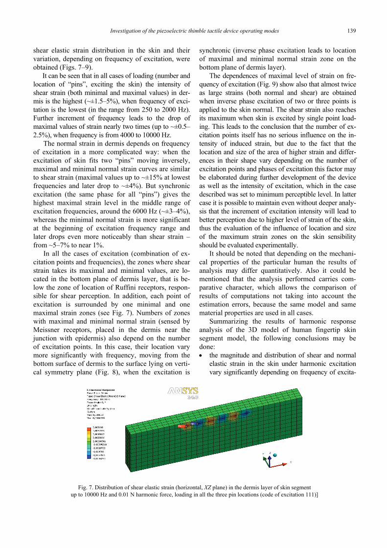
It can be seen that in all cases of loading (number andlocation of “pins”, exciting the skin) the intensity ofshear strain (both minimal and maximal values) in der-mis is the highest (~±1.5–5%), when frequency of exci-tation is the lowest (in the range from 250 to 2000 Hz).Further increment of frequency leads to the drop ofmaximal values of strain nearly two times (up to ~±0.5–2.5%), when frequency is from 4000 to 10000 Hz.
The normal strain in dermis depends on frequencyof excitation in a more complicated way: when theexcitation of skin fits two “pins” moving inversely,maximal and minimal normal strain curves are similarto shear strain (maximal values up to ~±15% at lowestfrequencies and later drop to ~±4%). But synchronicexcitation (the same phase for all “pins”) gives thehighest maximal strain level in the middle range ofexcitation frequencies, around the 6000 Hz (~±3–4%),whereas the minimal normal strain is more significantat the beginning of excitation frequency range andlater drops even more noticeably than shear strain –from ~5–7% to near 1%.
In all the cases of excitation (combination of ex-citation points and frequencies), the zones where shearstrain takes its maximal and minimal values, are lo-cated in the bottom plane of dermis layer, that is be-low the zone of location of Ruffini receptors, respon-sible for shear perception. In addition, each point ofexcitation is surrounded by one minimal and onemaximal strain zones (see Fig. 7). Numbers of zoneswith maximal and minimal normal strain (sensed byMeissner receptors, placed in the dermis near thejunction with epidermis) also depend on the numberof excitation points. In this case, their location varymore significantly with frequency, moving from thebottom surface of dermis to the surface lying on verti-cal symmetry plane (Fig. 8), when the excitation is
synchronic (inverse phase excitation leads to locationof maximal and minimal normal strain zone on thebottom plane of dermis layer).
The dependences of maximal level of strain on fre-quency of excitation (Fig. 9) show also that almost twiceas large strains (both normal and shear) are obtainedwhen inverse phase excitation of two or three points isapplied to the skin normal. The shear strain also reachesits maximum when skin is excited by single point load-ing. This leads to the conclusion that the number of ex-citation points itself has no serious influence on the in-tensity of induced strain, but due to the fact that thelocation and size of the area of higher strain and differ-ences in their shape vary depending on the number ofexcitation points and phases of excitation this factor maybe elaborated during further development of the deviceas well as the intensity of excitation, which in the casedescribed was set to minimum perceptible level. In lattercase it is possible to maintain even without deeper analy-sis that the increment of excitation intensity will lead tobetter perception due to higher level of strain of the skin,thus the evaluation of the influence of location and sizeof the maximum strain zones on the skin sensibilityshould be evaluated experimentally.
It should be noted that depending on the mechani-cal properties of the particular human the results ofanalysis may differ quantitatively. Also it could bementioned that the analysis performed carries com-parative character, which allows the comparison ofresults of computations not taking into account theestimation errors, because the same model and samematerial properties are used in all cases.
Summarizing the results of harmonic responseanalysis of the 3D model of human fingertip skinsegment model, the following conclusions may bedone:• the magnitude and distribution of shear and normal
elastic strain in the skin under harmonic excitationvary significantly depending on frequency of excita-
Fig. 7. Distribution of shear elastic strain (horizontal, XZ plane) in the dermis layer of skin segmentup to 10000 Hz and 0.01 N harmonic force, loading in all the three pin locations (code of excitation 111)]

R. BANSEVICIUS et al.140
tion (shear strain – from ~±0.5% to 2.5%, normal– from ~±15% to near 1%);
• in most cases maximal strains are obtained withlower frequencies of excitation (250–4000 Hz);
• number of maximal and minimal strain zones de-pend on number of excitation points;
• maximal and minimal shear strain zones are lo-cated in the bottom plane of dermis layer;
• location of zones with maximal and minimal nor-mal strain vary more significantly with frequency,moving from bottom surface of dermis to its mid-dle or even top surface.
Fig. 8. Distribution of normal elastic strain (vertical, Y axis) in the dermis layer of skin segmentup to 2000 Hz and 0.01 N harmonic force loading in the center pin location (code of excitation 010)]
Fig. 9. The dependences of maximal values of the elastic strain in dermis on frequency of excitation:(a) normal strain (Y direction); (b) shear strain (XZ plane).
Solid lines represent maximal strain, dotted – minimal, colours of minimal and maximal strain curves for each case are the same
Investigation of the piezoelectric thimble tactile device operating modes 141
It can be stated that the tactile perception of infor-mation, delivered by three vibrating pins, in tactiledevice may be influenced by configuration of excita-tion points (their number and phase of loading) andthe frequency of excitation.
4. Discussion
Aspiration in helping to improve the quality of lifeof the blind and visually impaired lead up to designand development of a wide variety of devices deliv-ering to individuals information about surroundings.Most interesting approaches are described below.
“The Forehead Retina” system observes 3D envi-ronment by video camera mounted on sunglasses.Information from camera is analyzed by computer andconverted to signals activating 512 electrodes affect-ing forehead skin, thus providing blind or visuallyimpaired about objects surrounding them [11] andhelping to orient and move outside.
Similar (optical scanning) principle is imple-mented in “Magic Finger” device [12], which can beused for reading information on various surfaces.“Magic Finger”, equipped with a pair of optical sen-sors, is able to recognize what it touches (32 differentsurface textures with 98 percent accuracy), and withthis information turn various surfaces into interfacesfor devices or a way of passing information. However,this device does not make any tactile influence on theuser finger.
“wUbi-Pen” device (haptic stylus) [13] also readsgraphic and symbolic information from computerscreen or mobile device in optical way (by camera)but differently than “Magic Finger” transfers it to userin tactile way (3 × 3 pins block, 3 mm between pins).The device may “inform“ its user by vibration, impactor sound, it allows even simple contours to be drawn,however is unable to recognize colour of the objectdisplayed, its size, determined by the way of handlingit, which seems to be one more quite important disad-vantage.
“Tesla Touch” [14] – technology allowing deliv-ering users of devices with touch interfaces with tac-tile feedback thus ensuring some dynamic tactilefeedback. It is based on the electrovibration principle:it does not use any moving parts and provides a widerange of tactile feedback sensations to fingers movingacross a touch surface by variable friction force. Themain problem of this system is that it is necessary touse high voltages to control the friction force causedby electrovibration.
According to the destination (usage with touch-based interfaces the popularity of which has beenrapidly growing) the piezoelectric thimble under de-velopment is close to the two last devices mentioned.It transforms information shown on the screen intoclassical tactile excitation of the finger skin like“wUbi-Pen”, but is more compact and in addition isdesigned with intention to inform its user about thecolor of the objects displayed on the interface either,the same as “Tesla Touch”. But due to the principle ofgeneration of the tactile signal piezoelectric thimbleseems to be cheaper and less energy consuming thanthe latter (at least for the moment), which herewithincreases mobility of its user, and more effective (in-formative), because excites finger skin not only duringmovement of the finger on the surface of the screen ofmobile device.
Perhaps the main problem faced by developersof various tactile devices is evaluation of their tac-tile efficiency. That is why most frequently exactinformation about the regimes of skin excitation isnot provided when describing such devices, ex-cluding general principles, for example, arrange-ment of the static excitation points defined yet byBraille and if to speak about devices describedabove – “wUbi-Pen”.
One of the ways of obtaining the necessary data isto investigate the stress–strain state of the human (oranimal) skin by means of computational methods.There are a lot of skin computational models devel-oped by different authors differing in description ofskin sort (finger, arm, sole, leg, etc.) geometry (shape,number and thickness of layers [15]), description ofmaterial properties (from isotropic linear elastic toviscoelastic, etc.), type of problem (plane [16]–[19] orspatial, 3D, [20], [21] normal ant tangential, singleand two point indentation [22] static or dynamicloading [23], and so on.
In the case under discussion to have ability tocheck the influence of a combination of several ex-citation points a 3D solid model was used (if therewas only one needle far simpler plane model wouldbe enough). A quite important feature of the modelused in this research is the presence of the thinnestexternal layer of the skin – stratum corneum, whoseYoung’s modulus in the case of the finger skin issignificantly higher than for most of the remainingskin of human body. Materials were treated as line-arly elastic because of the relatively small excitationsignal level and also having the aim to reduce time ofcomputations of this study, treated by the authors aspilot one. One more simplification – the direct har-monic excitation of the skin instead of modeling

R. BANSEVICIUS et al.142
contact interaction between moving pin tip and skinsurface, because in such a case transient (or timehistory) solution should be performed, which wouldbe extremely time consuming. There again, not hardkinematic, but namely force excitation was used,which noticeably reduces the severity of such simpli-fication. Excitation frequency range is extended in-tentionally having in mind the possibility to affectskin by piezoelectric thimble pins glued to the skinsurface (presuming that this untypical case of highfrequency kinematic loading may lead to interestingoutcome).
To have more precise and adequate info about thebehavior and the sensitivity of the fingertip skin ex-cited by pins of piezoelectric thimble the computa-tional model free of facilitations mentioned above iscurrently under development by the authors.
5. Conclusions
Summarizing the results of harmonic responseanalysis of the 3D finger–needle contact zone, thefollowing conclusions can be made:• The magnitude and distribution of shear and nor-
mal elastic strain in the skin under harmonic exci-tation vary significantly, depending on frequencyof excitation (shear strain – from ~±0.5% to 2.5%,normal – from ~±15% to near 1%);
• In most cases maximal strains are obtained withlower frequencies of excitation (up to 4000 Hz);
• Numbers of maximal and minimal strain zonesdepend on the number of excitation points on thehuman finger skin;
• Maximal and minimal shear strain zones are lo-cated in the bottom plane of the human skin dermislayer;
• Location of zones with maximal and minimalnormal strain vary more significantly with fre-quency, moving from bottom surface of dermis toits middle or even top surface.Research results show that configuration of exci-
tation needles (number of the points and oscillatingphase) and their frequencies can influence the infor-mation transferring to the blind human finger. Thisinformation will be utilised when developing piezoe-lectric actuators with 2 and 3 oscillating needles.
Acknowledgement
This work has been supported by Research Council of Lithuania,Project No. MIP-042/2011.
References
[1] AZUBALIS M., BANSEVICIUS R., Computer mouse type input–output device, State Patent of Lithuania, No. 5159 B, 2002.
[2] AZUBALIS M., BANSEVICIUS R., TOLOCKA R. T., JURENAS V.,Research of the tangential movement of the tactile device,Ultragarsas ISSN:1392-2114, Technologija, Kaunas, 2004,Vol. 3, No. 52, 33–37 (in Lithuanian).
[3] GRIGAS V., TOLOČKA R.T., ŽILIUKAS P., Dynamic interactionof fingertip skin and pin of tactile device, Journal of Soundand Vibration, London, Elsevier Science. ISSN 0022-460X.2007, Vol. 308, Iss. 3–5, 447–457.
[4] BANSEVIČIUS R., DRAGAŠIUS E., MAŽEIKA D., JŪRĖNAS V.,SKIEDRAITĖ I., ŽVIRONAS A., R&D of the device for blind toconceive 2D graphical information, Journal of Vibroengi-neering, 2012, Vol. 14, 1444–1449.
[5] Skin Rejuvenation with Ablative Laser.:http://www.mylooks.co.uk/treatments/ablative-laser/skin-rejuvenation. Accessed 5 February 2014
[6] GERLING G.J., THOMAS W., The Effect of Fingertip Microstruc-tures on Tactile Edge Perception, Proceedings of the First JointEurohaptics Conference and Symposium on Haptic Interfacesfor Virtual Environment and Teleoperator Systems, World Hap-tics 2005, First Joint, Conference Publications, 63–72.
[7] MAENO T., KOBAYASHI K., YAMAZAKI N., Relationship be-tween the Structure of Human Finger Tissue and the Locationof Tactile Receptors, Bulletin of JSME International Journal,1998, Vol. 41, No. 1, C, 94–100.
[8] HU J., XIN D., WANG R., Dependence of tactile sensation ondeformations within soft tissues of fingertip, ISSN 1 746-7233,England, UK World Journal of Modelling and Simulation,2007, Vol. 3, No. 1, 73–78.
[9] LEDERMAN S.J., Skin and touch, Queen’s University, http://psycserver.psyc.queensu.ca/lederman/106.pdf. Accessed 5 Feb-ruary 2014.
[10] GOULD W.R., VIERCK C.J., LUCK M.M., Cues supportingrecognition of the orientation or direction of movement of tac-tile stimuli, [in:] D.R. Kenshalo (ed.), Sensory Functions of theSkin in Humans, Plenum Press, New York 1979, 63–78.
[11] KAJIMOTO H., KANNO Y., TACHI S., Forehead Electro-tactileDisplay for Vision Substitution, EuroHaptics, Paris, France,July 3–6, 2006, http://citeseerx.ist.psu.edu/viewdoc/download?doi=10.1.1.79.6965&rep=rep1&type=pdf, Accessed 14 March2014.
[12] SZONDY D., Magic Finger turns any surface into a touch inter-face, October, 2012, http://www.gizmag.com/magic-finger-interface/24544/, Accessed 14 March 2014.
[13] KYUNG KI-UK. WUBI-PEN: Windows Graphical User InterfaceInteracting With Haptic Feedback Stylus. SIGGRAPG 2008,The 35th International Conference and Exhibition on ComputerGraphics and Interactive Techniques. http://www.siggraph.org/s2008/attendees/newtech/11.php, Accessed 14 March 2014.
[14] BAU O., POUPYREV I., ISRAR A., HARRISON Ch., TeslaTouch:Electrovibration for Touch Surfaces, 23rd ACM UIST Sym-posium, USA, New York 2010. http://www.chrisharrison.net/projects/teslatouch/teslatouchUIST2010.pdf, Accessed 14 March2014.
[15] THALMANN N.M., KALRA P., LÉVÊQUE J. L., BAZIN R.,BATISSE D., QUERLEUX B.A., Computational Skin Model:Fold and Wrinkle Formationm IEEE Transactions on Infor-mation Technology in Biomedicine, Dec. 2002, Vol. 6, Iss. 4,317–323.

Investigation of the piezoelectric thimble tactile device operating modes 143
[16] RICKER S.L., ELLIS R.E., 2-D Finite-Element Models ofTactile Sensors, Proceedings of the IEEE International Con-ference Robotics and Automation, 1993, Vol. 1, 941–947.
[17] MAENO T., KAWAI T., KOBAYASHI K., Analysis and Design ofa Tactile Sensor Detecting Strain Distribution Inside anElastic Finger, Proceedings of the IEE/RSJ Intl. Conferenceon Intelligent Robots and System, Victoria, B.C., Canada,October 1998, Vol. 3, 1658–1663.
[18] MORI M., MAENO T., YAMADA Y., Method for DisplayingPartial Slip used for Virtual Grasp, Proceedings of theIEEE/RSJ Intl. Conference on Intelligent Robots and Sys-tems, Las Vegas, Nevada, October 2003, 3100–3105.
[19] An Investigation of the Mechanics of Tactile Sense UsingTwo-Dimensional Models of the Primate Fingertip, M. A.Srinivasan, K. Dandekar, Journal of Biomechanical Engi-neering, 1996 Feb., 118(1), 48–55.
[20] DANDEKAR K., RAJU B.I., SRINIVASAN M.A., 3-D Finite-Element Models of Human and Monkey Fingertips to Investi-
gate the Mechanics of Tactile Sense, Journal of BiomechanicalEngineering, October 2003, Vol. 125, Issue 5, 682–691.
[21] WU J.Z., WELCOME D.E., DONG R.G., Three-dimensionalfinite element simulations of the mechanical response of thefingertip to static and dynamic compressions, ComputerMethods in Biomechanics and Biomedical Engineering,ISSN 1025-5842 print/ISSN 1476-8259 2006 Feb., 9(1),55–63.
[22] WU J.Z., DONG R.G., RAKHEJA S., SCHOPPER A.W., SMUTZ W.P.,A structural fingertip model for simulating of the biomechanicsof tactile sensation, Medical Engineering and Physics, 2004,26, 165–175.
[23] NISHIYAMA J., TSAI C.-H.D., QUIGLEY M., IMIN KAO,SHIBATA A., HIGASHIMORI M., KANEKO M., An experimentalstudy of biologically inspired artificial skin sensor under staticloading and dynamic stimuli, Proceedings of the IEEE Inter-national Conference Robotics and Automation. Shanghai,China, 2011, 1778–1783.