Investigation of the mechanical properties of Friction ... · show the chemical composition,...
15
1 Investigation of the mechanical properties of Friction Stir Welded 6061 Al plates A.M. Khorsid [1] , A.A. Moustafa [2] , and I. Sabry [3] [1] Prof. Dr. Production Eng., Faculty of Eng., Tanta University, ARE [2] Lecturer Production Eng., Higher Institute of Eng., Hoon , GSPLAJ [3] Graduate Engineer, Production Eng., Faculty of Eng., Tanta University, ARE Abstract: The objective of this work was to investigate the mechanical and metallurgical properties in order to demonstrate the feasibility of friction stir welding (FSW) for joining of 6061Aluminum Alloy. Four rotational speeds, 720, 910, 1120, and 1400 r.p.m and three traverse speeds 16, 20, and 31.5 mm/min were applied. Metallographic examinations of friction stir welded plates were carried out using optical and scanning electron microscopy. Hardness profiles of welded joints were measured using Vickers hardness testing. The hardness profile at transfer cross sections showed marked decrease in hardness values depending on welding conditions and position of hardness measurements. The FSW welds exhibited higher joint efficiencies relative to conventional welding techniques. Key words: friction stir welding (FSW), Al alloys, mechanical properties, microstructure Introduction: It is well known that, Al alloys have many specific properties and can be used for many structural parts that need both light weight and high mechanical properties. Recently, Al alloys have been used in the transportation industry such as high speed trains, shipping and external fuel tanks of rockets [1]. Structural parts and frames composed of Al alloys must be welded using the sound welding technique commonly employed in this industry. Fusion welding of commercial aluminum alloys is generally difficult and not recommended for some aluminum alloy groups. The presence of protective tenacious oxide film on aluminum alloys is responsible for such difficulties. Extensive surface preparations to remove the oxide film are necessary before welding of aluminum alloys. Many welding defects, such as voids, hot cracking and distortion related to the melting and solidification were formed in the weld zone when applying fusion welding. The main problems of fusion welded Al alloys are the precipitates resolution, the loss of the solid state bonding. Thus, the solid state bonding technique is highly recommended to solve these problems. Friction stir welding (FSW) technique is recently developed to overcome many of such difficulties and eliminate the needs for special surface preparation or cleaning prior to welding of aluminum alloys. [1,2]. FSW is considered to be a solid state welding process in which the two parts of weld joint are brought into contact and the interface is strongly forged together under the effect of heavy hot plastic deformation caused by the inserted rotating stir probe pin[3].. Frictional heating is produced as a result of intimate contact between the rotating probe shoulder and the upper surfaces of work pieces. The maximum weld zone temperature was estimated to be in order of 0.6 – 0.8 T m, where T m is the absolute melting temperature [4-7]. The process variables are mainly the rotational speed, the traverse speed, the holding pressure, and the tool design. The characteristics of friction stir welding process make it attractive in advanced applications such as aerospace, automotive and shipbuilding. FSW technique has the potential to avoid significant changes in microstructure and
Transcript of Investigation of the mechanical properties of Friction ... · show the chemical composition,...

1
Investigation of the mechanical properties of
Friction Stir Welded 6061 Al plates A.M. Khorsid[1], A.A. Moustafa[2], and I. Sabry[3]
[1] Prof. Dr. Production Eng., Faculty of Eng., Tanta University, ARE [2] Lecturer Production Eng., Higher Institute of Eng., Hoon , GSPLAJ
[3] Graduate Engineer, Production Eng., Faculty of Eng., Tanta University, ARE Abstract:
The objective of this work was to investigate the mechanical and metallurgical properties in order to demonstrate the feasibility of friction stir welding (FSW) for joining of 6061Aluminum Alloy. Four rotational speeds, 720, 910, 1120, and 1400 r.p.m and three traverse speeds 16, 20, and 31.5 mm/min were applied. Metallographic examinations of friction stir welded plates were carried out using optical and scanning electron microscopy. Hardness profiles of welded joints were measured using Vickers hardness testing. The hardness profile at transfer cross sections showed marked decrease in hardness values depending on welding conditions and position of hardness measurements. The FSW welds exhibited higher joint efficiencies relative to conventional welding techniques. Key words: friction stir welding (FSW), Al alloys, mechanical properties, microstructure
Introduction:
It is well known that, Al alloys have many specific properties and can be used for many structural parts that need both light weight and high mechanical properties. Recently, Al alloys have been used in the transportation industry such as high speed trains, shipping and external fuel tanks of rockets [1]. Structural parts and frames composed of Al alloys must be welded using the sound welding technique commonly employed in this industry. Fusion welding of commercial aluminum alloys is generally difficult and not recommended for some aluminum alloy groups. The presence of protective tenacious oxide film on aluminum alloys is responsible for such difficulties. Extensive surface preparations to remove the oxide film are necessary before welding of aluminum alloys. Many welding defects, such as voids, hot cracking and distortion related to the melting and solidification were formed in the weld zone when applying fusion welding. The main problems of fusion welded Al alloys are the precipitates resolution, the loss of the solid state bonding. Thus, the solid state bonding technique is highly recommended to solve these problems. Friction stir welding (FSW) technique is recently developed to overcome many of such difficulties and eliminate the needs for special surface preparation or cleaning prior to welding of aluminum alloys. [1,2]. FSW is considered to be a solid state welding process in which the two parts of weld joint are brought into contact and the interface is strongly forged together under the effect of heavy hot plastic deformation caused by the inserted rotating stir probe pin[3].. Frictional heating is produced as a result of intimate contact between the rotating probe shoulder and the upper surfaces of work pieces. The maximum weld zone temperature was estimated to be in order of 0.6 – 0.8 Tm, where Tm is the absolute melting temperature [4-7]. The process variables are mainly the rotational speed, the traverse speed, the holding pressure, and the tool design. The characteristics of friction stir welding process make it attractive in advanced applications such as aerospace, automotive and shipbuilding. FSW technique has the potential to avoid significant changes in microstructure and

2
mechanical properties [5, 6]. During FSW process a large amount of straining occurs at weld centerline, i.e. stir zone, the structure undergoes continuous dynamic recrystallization to grain of similar dimensions as the sub grains [7, 8].
Many researchers tried to study and explain the stir welding process. Reynolds et al. [9, 10] suggested that FSW process can be roughly described as in situ extrusion process wherein the tool shoulder, the pin, the weld packing plate, and cold base metal outside the weld zone form an “extrusion chamber” which moves relative to the work piece They concluded that the extrusion around the pin combined with the stirring action at the top of the weld created within the pin diameter a secondary, vertical, circular motion around the longitudinal axis of the weld.
Guerra et al. [ 11] studied the material flow of FSW 6061 Al. by means of a faying surface tracer and a pin frozen in place at the end of welding. They concluded that the material was moved around the pin in FSW by two processes. First, material on the advancing side front of a weld entered into a zone that rotates and advances simultaneously with the pin .The material in this zone was very highly deformed and sloughed off behind the pin in arc shaped features[11].This zone exhibited high Vickers micro hardness of 95. Second, material on the retreating front side of the pin extruded between the rotational zone and the parent metal and in the wake of the weld fills in between material sloughed off from the rotational zone. His zone exhibited low Vickers micro hardness of 35. Further, they pointed out that material near the top of the weld (approximately the upper one-third) moved under the influence f the shoulder rather than the threads on the pin.
Colligan[12,13] studied the material flow behavior during FSW of aluminum alloys
They concluded that not all the material in the tool path was actually stirred and rather a large amount of the material was simply extruded around the retreating side of the welding tool pin and deposited behind.
London et al. [ 14] investigated material flow in FSW of 7050 Al-T7451 monitored with 6061 Al-30%SiCp and Al-20% W composite makers. They showed that the amount of material deformation in the FSW weld depending on the locations relative to the pin Ouyang and Kovacevic [15] examined the material flow behavior in friction stir butting welding of 2024 Al to 6061 Al.plates. Three different regions were revealed in the weld zone. The first was mechanically mixed region characterized by the relatively uniformly dispersed particles of different alloy constituens. The second was the stirring- induced plastic region consisting of alternative vortex-like lamellae of the two aluminum alloys. The third was the unmixed region consisting of fine equiaxed grains of the 6061 Al alloy.
They reported that in the welds the contact between different layers is intimate, but the mixing is far from complete. However, the bonding between the aluminum alloys was complete. Further, they attributed the vortex-like structure and alternative lamellae to the stirring action along the welding direction.
Murr and co-workers[ 16 ,18,19,and 31]investigated the solid – state flow visualization in friction stir butt welding of 2024Al to 6061 and copper to 6061 Al.
A recent investigation on friction stir lap welding of 2195Al to 6061 Al revealed that there is large vertical movement of material within the rotational zone caused by wash and backwash of the threads[11].they stated that the material entering this zone followed an unwound helical

3
trajectory formed by the rotational motion, the vertical flow, and the translational motion of the pin.
Krishnan[20] investigated the deformation of onion rings in FSW of 6061Al and 7075Al alloys by using different FSW parameters. It was suggested that the FSW process can be thought to be simply extruding one layer of semi cylinder in one rotation of the tool and a cross-section slice through such a set of semi cylinder results in the familiar onion ring structure.
Billas et al. [ 21] suggested that the formation of onion rings was attributed to the reflection of material flow approximately at the imaginary walls of the groove that would be formed in the case of regular milling of the metal. Although microstructure examinations revealed that an abrupt variation in grain size and/or precipitate density at these rings[22,23].It is noted that the understanding of formation of onion rings is far from complete and an insight into the mechanism of onion ring formation would shed light on the overall material flow occurring during FSW.
Tang et al. [24] made an attempt to measure the heat input and temperature distribution within FSW by embedding thermocouples in the region to be welded in plates of 6061 Al -T6 They reported that the thermocouple at the weld center was not destroyed by the pin during welding but did change position slightly due to plastic flow of material ahead of the pin[24]. They also studied the effect of shoulder on the temperature field by using two tools with and without pin and showed that no significant difference in temperature when the thermocouples placed at equal distance from weld seam but on opposite sides of the weld.
It is reported that in FSW OF 1050Al, the peak temperature increased linearly from 190 C to 310 C with increasing tool rotation from 560 to 1840 rpm at a constant traverse speed of 155 mm/min[ 25,26,27] .
Frigaad et al. [ 28] developed a numerical three dimensional heat flow for FSW of age hardenable aluminum alloy based on the finite differences.
The effect of FSW parameters on temperature was further examined by Arbagast and Hartley[29]. They reported that for a given tool geometry and depth of penetration, the maximum temperature was observed to be a strong function of rotation rate(rpm) while the rate of heating was a strong function of the traverse speed.
In summary , many factors influence the thermal profiles during FSW. It can be concluded that,: maximum temperature rise within the weld zone is below the melting point of aluminum; tool shoulder dominates heat generation during FSW ; and maximum temperature increases with increasing tool rotation rate at constant tool traverse speed and decreases with increasing traverse speed at a constant tool rotation rate. Also it can be concluded that maximum temperature rise occurs at the top surface of weld zone.
The aim of the work is to study the effect of welding variables on the mechanical properties of the weldmets .

4
Experimental Work:
Materials:
The material used in this study (6061 Al alloy) , was received from Misr Aluminum Company in the form of cold rolled plates 100x 6.5 mm cross section. Tables 1 ,2 and 3 show the chemical composition, mechanical and physical properties of.6061 Al alloy .
Table (1) : chemical composition (wt%) of 6061 Al
Alloy Si Fe Cu Mn Mg Zn Cr Ti Approximate melting
range
6061 0.6 0.7 0.28 0.15 0.2 0.25 0.2 0.15 582-658 C0
Table (2): Mechanical Properties of 6061 Al /composite
Description σy MPa σult MPa E1 % HV
Al6061 85 85 16 62
Table. ( 3 ) Physical Properties of 6061 Al alloy
Description Coefficient of Thermal Expansion mm/mm oC
Thermal Conductivity W/m.oK
at (25oC-77oF) Density g /cm
Elastic ModulusGPa
Al6061 (22‐24) × 106 150‐180 2.7 70
No heat treatment processes were done. Welding specimens were machined to the following dimensions (75 *150 *5 mm.) . A standard vertical milling machine was specially prepared to conduct the experiments.
A special tool was designed to be adopted in the vertical milling machine head.
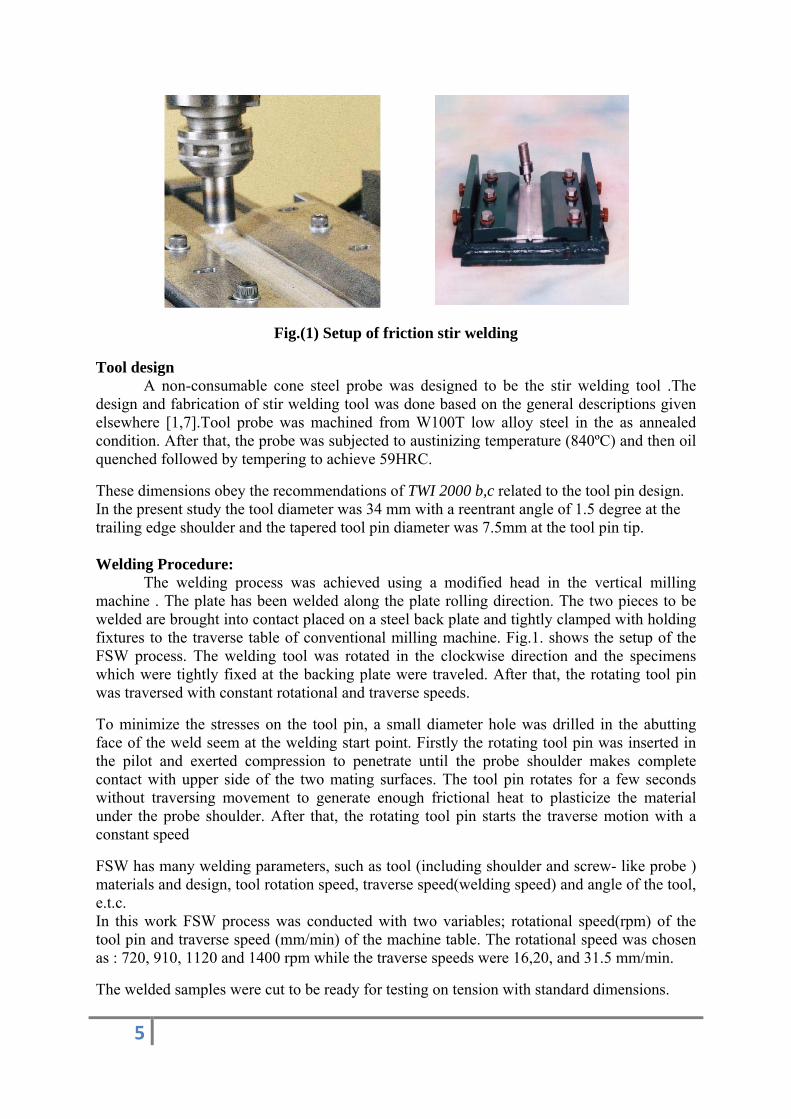
A conical head tool with a shoulder was used A special fixture setup was designed and fabricated to clamp the two specimens to be welded. The setup proved to be rigid and reliable. (Fig. 1).
5
Fig.(1) Setup of friction stir welding
Tool design A non-consumable cone steel probe was designed to be the stir welding tool .The
design and fabrication of stir welding tool was done based on the general descriptions given elsewhere [1,7].Tool probe was machined from W100T low alloy steel in the as annealed condition. After that, the probe was subjected to austinizing temperature (840ºC) and then oil quenched followed by tempering to achieve 59HRC.
These dimensions obey the recommendations of TWI 2000 b,c related to the tool pin design. In the present study the tool diameter was 34 mm with a reentrant angle of 1.5 degree at the trailing edge shoulder and the tapered tool pin diameter was 7.5mm at the tool pin tip. Welding Procedure: The welding process was achieved using a modified head in the vertical milling machine . The plate has been welded along the plate rolling direction. The two pieces to be welded are brought into contact placed on a steel back plate and tightly clamped with holding fixtures to the traverse table of conventional milling machine. Fig.1. shows the setup of the FSW process. The welding tool was rotated in the clockwise direction and the specimens which were tightly fixed at the backing plate were traveled. After that, the rotating tool pin was traversed with constant rotational and traverse speeds.
To minimize the stresses on the tool pin, a small diameter hole was drilled in the abutting face of the weld seem at the welding start point. Firstly the rotating tool pin was inserted in the pilot and exerted compression to penetrate until the probe shoulder makes complete contact with upper side of the two mating surfaces. The tool pin rotates for a few seconds without traversing movement to generate enough frictional heat to plasticize the material under the probe shoulder. After that, the rotating tool pin starts the traverse motion with a constant speed
FSW has many welding parameters, such as tool (including shoulder and screw- like probe ) materials and design, tool rotation speed, traverse speed(welding speed) and angle of the tool, e.t.c. In this work FSW process was conducted with two variables; rotational speed(rpm) of the tool pin and traverse speed (mm/min) of the machine table. The rotational speed was chosen as : 720, 910, 1120 and 1400 rpm while the traverse speeds were 16,20, and 31.5 mm/min.
The welded samples were cut to be ready for testing on tension with standard dimensions.

6
Testing:
To prepare the welding zone for metallographic examinations, the samples were ground and fine polished to the mirror surface and then washed, cleaned and dried.
Vickers hardness profile near the weld zone was measured on a cross section and perpendicular to the welding direction with a 100kgf load for 10s.The readings were plotted as a function of distance from welding center. Tensile tests were carried out at room temperature using an Instron–type computerized testing machine with cross-head speed of 1.9 x10⁻² mm/s. To determine the tensile strength of stir zone, tensile test specimens were sectioned in the longitudinal direction to the weld line by an electro discharge machining( EDM.). The specimens were machined and ground, then cleaned with methanol and dried in a furnace to avoid inclusions in welding zone. The specimens were prepared to be tested on hardness, tension, and subjected to optical and scanning electron microscopy (SEM).Microstructural changes from the weld zone to the unaffected base metal were examined with optical microscope and SEM (Scanning Electron Microscope).
The light optical microscope was used to examine the welded specimens delineated the salient microstructural features in the welded parts and to compare grain structure. Eching with keller's reagent was done, then optical microscope was used. Figures 2 and 3 represent a typical examples of the difference between various welding regions due to [ 6,34 ] respectively.
Scanning electron microscopies[ISM-T330A] was used for examining the welded samples and study the micro structural features of the polished samples
All of the weld metallography was performed on a plane perpendicular to the welding direction at the weld centerline . Some tests were done to inspect the defects in welding zone.
Results and Discussion The weld root surface of all investigated weldments showed visually and
ultrasonically a well joined sound flat surface. The increase in stir-probe rotational speed enhanced the weld soundness which may be a result of softening process associated with dynamic recovery and recrystallization process at the weld at the nugget.
Mechanical Properties
Hardness measurements across the centerline of stir welded specimens showed markedly low hardness values at weld center line (Fig 4). The graphs represent the typical behavior as of some FSW of aluminum alloys [4, 5]. Such softening phenomenon can be attributed to the dynamic recovery and dynamic re-crystallization process during FSW of aluminum alloys .It could be concluded that when rotational speed is more than 1120 rpm there exists an adversely affects on the softening process. This could be attributed to the higher degree of strain hardening in weld nugget. On the other hand, the degree of recrystallization increases with the increase in both rotational and traverse speeds. This explanation was reached also by many researchers [4, 5, 32, 33, 34, and 37].

7
F main sofact thabecausemarkedto 31.5mdecreasprocessmechan(10) Anhighly markedless thameasurewelded
7
A. UnB. HeC. ThD. W
Fig.3.MicroFor the pre
oftening meat dislocatioe of the redly decreasemm/min. Thse in tensile s. Changes inisms, i.e. thnd the extrastable micr
dly increasean 30 % of tements of specimens
naffected maeat affected hermo‐mechWeld nugget (
Fig.2
ostructure sent alloy it
echanisms don climb andelatively hige to about 80his behaviostrength co
in tensile prhe softeningaordinary grostructure d to about the specimehardness, uare shown
aterial zone (HAZ)
hanically affe(Part of therm2. Microstru
Classificatit is obvious
during FSWd cross-slipgh stacking0-90% of th
or also has bould be undroperties ang mechanisgrain refinin
constituenfour time t
en gage lengultimate tenin figures 4
ected zone (Tmo‐mechaniucture classi
ion and heas that dynam
W. This obsep occur readg fault enehe base metbeen observderstood in tnd hardnesssm due to dng mechani
nts. The tenthe base megth and mainsile streng
4-7 respectiv
TMAZ) ically affecteification.
at affected mic recoveryervation is ndily in alumergy. The rtal when tra
ved when rothe light of s after FSWdynamic re-ism due to nsile ductilietal ductilityinly concength, yield svely.
ed zone
Zone (aftey and re-crynot surprisi
minum at eleresults of haverse speedotational spef the dynami
W are resultacrystallizatiheavy plas
ity was esty. Specime
ntrated at thstress and
er referenceystallizationng, conside
evated temphardness shd increases eed increaseic re-crystaant of two dion as givenstic deformtimated and
en’s elongate weld nugelongation
e) n are the ering the peratures howed a from 16
ed. Such allization different n in fig.
mation of d found tion was get. The for the

8
Vickers Hardness vs Rotational Speed
30
35
40
45
50
55
60
65
70
600 700 800 900 1000 1100 1200 1300 1400 1500 Rotational Speed (RPM)
Vic
kers
Har
dnes
s (H
V)
16 mm/min20mm/min31.5mm/min
Ultimate Tensile Strength vs Rotational Speed
105
110
115
120
125
130
135
600 700 800 900 1000 1100 1200 1300 1400 1500 Rotational Speed (RPM)
Ult.
Ten
. Str
engt
h (M
Pa)
16mm/min20mm/min31.5mm/min
Yeild Stress vs Rotational Speed
6065
707580
859095
100105
600 700 800 900 1000 1100 1200 1300 1400 1500 Rotational Speed (RPM)
Yei
ld S
tres
s σ
y (M
Pa)
16 mm/min 20 mm/min 31.5 mm/min
Elongation vs Rotational Speed
14
14.25
14.5
14.75
15
15.25
15.5
15.75
16
600 700 800 900 1000 1100 1200 1300 1400 1500 Rotational Speed (RPM)
Elo
ngat
ion
(%)
16 mm/min20mm/min31.5mm/min
FIGURE 4: Relationship between Vickers Hardness at Center Line and Rotational Speed
FIGURE 5: Relationship between Elongation and Rotational Speed
FIGURE 6: Relationship between Yield Stress and Rotational Speed
Figure7: Relationship between Elongation and Rotational Speed

9
Macrostructure All welded specimens were first subjected to visual inspection of weld face surface. Macroscopic examination of transverse and longitudinal cross section- showed defect free sound weldments, produced under all applied experimental conditions. Uniform semicircular surface ripples in weld track were observed. These surface ripples, which have onion rings configuration, were caused by the final sweep of the trailing edge of the continuously rotating tool shoulder. A similar observations were made by many researchers [5, 6, 35, and 36]. Figure 8 shows surface ripples in the weld track
Fig. 8 Surface ripples in the weld track
In most investigated specimens, such ellipsoids characterize the macrostructure of FSW process [5-10]. They represent plastic deformation increments that developed as the rotating tool pin moved through the joint interface. The presence of such flow lines indicates that, during the FSW process, the material at the interface of abutting joint, i.e. at weld centerline was strongly stirred and mixed together, so that it can be considered as a viscous fluid, which makes swirl movements under the probe- shoulder. As the probe- pin moved in traverse direction, the temperature decreased, the layer viscosity increased. The transverse diameter of inner ellipse decreased from 3.28 to 1.70 mm. as the rotational speed increases from 720 to1400 r.p.m., while the width of the stirring zone was slightly affected by changing rotational speed. It was found to be 7.8, 7.16, and 7.02 mm. at 720,910, and1400 r.p.m. respectively. The increase in rotational speed may decrease the viscosity of plasticized material at the centerline of the weld around the stir probe, and consequently decrease the diameter of inner stirring ring. The width of stir zone may be expected to be dependent on the balance between the total heat input and the cooling in the plasticized material. The geometry of such swirl patterns was found to be in conjunction with welding conditions, i.e. the degree of plastic deformation and the design of stir probe. Figures 9 and10 shows a macro structure of the cross section in the weld zone and the corresponding microstructure of the different welding zone regions respectively.Fig.9 exhibited four distinct micro structural zones; (a) base metal ,(b) heat affected zone HAZ,(c) thermo mechanically affected zone TMAZ and (d) dynamically re-crystallization zone DRZ. The plastic deformation at weld interface occurred at a wide range of strain rate and temperature depending on the location; the distance from weld centerline. Therefore, at weld nugget two competing mechanisms may acted simultaneously, namely strain hardening and softening mechanisms, and the observed structure may be the resultant of a repeated cycles of deformation and re-crystallization. A significant micro structural change of the investigated alloy was the re-crystallization process of the weld joint.

10
Fig.9 Cross section of friction stir weldement of 6061 Al alloy, showing the different weld zone regions;(a) base metal ,(b) heat affected zone HAZ,(c) thermo mechanically
affected zone TMAZ and (d)dynamically recrystallization zone DRZ.
(a)
(b)
(c)
(d)
Fig.10 microstructures of the different weld zones:
(a) Base metal, (b) HAZ, (c) TMAZ and
(d) DRZ. For 6061 Al alloy welded at 1400 r.p.m. and 16 mm/min.

11
Hardness Measurements at the Cross Section of the Weld The hardness measurements shown in Figs. 11 represent the hardness profiles for
specimens at different rotational speed, and different traverse speeds. The hardness profiles were taken at three different locations across the weld nugget, i.e. near the weld-face, at midway through the weld nugget, and near to the root of the FSW joint. The mean values were plotted against the distance from welding centerline. In general, the hardness decreases from the base metal towards the weld centerline. This typical profile is as for some of friction stir welded aluminum alloys [6, 7, 8, 32, and 33] On the other hand, it decreases from the weld root towards the weld face. However, the hardness profile shows a more or less saddle pattern near the weld centerline especially near the weld face. Such softening phenomenon has been attributed to the dynamic recovery and dynamic re-crystallization processes during FSW of aluminum alloys [34, 37]. The decrease in hardness from base metal to the centerline of weld nugget at constant rotational speed could be attributed to the higher degree of softening in the weld nugget. Changes in tensile properties and hardness after FSW represent the sum of two different mechanisms i.e. the softening mechanism due to dynamic re-crystallization as given in Figures 9 and 10, and extraordinary grain refining mechanism due to heavy plastic deformation of highly stable microstructure constituents. Due to heavy plastic deformation of highly stable microstructure constituents. Conclusion Remarks In the light of the present experimental results the following conclusions could be drawn. 1 - A swirl motion model was introduced to explain the good mixing at the abutting interface of
friction stir weld joint, 22 -- The weld soundness was improved by increasing the rotational speeds. 3 - The FSW of 6061 Al alloy has been proved to be efficient and the weldments found
defect free and the machine used and the designed tool proved to be reliable. 4 - Dynamic re-crystal1ization in the DRZ can be considered a continuous dynamic re-
crystallization (CDR) on the basis of dynamic recovery. Sub grain growth associated with absorption of dislocations into the boundaries is the CDR mechanisms.
5 - Friction stir welds exhibited joint efficiency relative to base metal hardness from 65% to 111% depending on welding conditions and measurements location although the observed tensile strength of F.S.W welded 6061 Al was much higher than that reported after welding of the same material with other weld processes.
6 - The FSW welds exhibit high ductility of stir zone depending on the welding conditions.

12
Vickers Hardness vs Distance From Welding Center
0
10
20
30
40
50
60
70
-50 -40 -30 -20 -10 0 10 20 30 40 50 Distance from Welding Center (mm)
Vic
kers
Har
dnes
s (H
V)
16 mm/min 720rpm20mm/min 720rpm31.5mm/min 720rpm
Vickers Hardness vs Distance From Welding Center
0
10
20
30
40
50
60
70
-50 -40 -30 -20 -10 0 10 20 30 40 50 Distance from Welding Center (mm)
Vic
kers
Har
dnes
s (H
V)
16 mm/min 910rpm20mm/min910rpm31.5mm/min 910rpm
Vickers Hardness vs Distance From Welding Center
0
10
20
30
40
50
60
70
-50 -40 -30 -20 -10 0 10 20 30 40 50 Distance from Welding Center (mm)
Vic
kers
Har
dnes
s (H
V)
16 mm/min 1120rpm20mm/min 1120rpm31.5mm/min 1120rpm
Vickers Hardness vs Distance From Welding Center
0
10
20
30
40
50
60
70
-50 -40 -30 -20 -10 0 10 20 30 40 50 Distance from Welding Center (mm)
Vic
kers
Har
dnes
s (H
V)
16 mm/min 1400rpm20mm/min 1400rpm31.5mm/min 1400rpm
Figure 11: Relationship between Vickers Hardness Versus Distance From Welding Center at cross section of the weld at Various Rotational and Traverse Speeds.
13
Reference [1]Dawes, C.J.; and Thomas, W.M.: “Friction Stir Process Welds Aluminum Alloys,”
Welding Journal, pp. 41–45, March 1996.
[2]Gittos, M.; and Threadgill, P.: “Joining Aluminum Alloy MMC,” Bulletin 5, TWI J., pp.104–105, September/October 1992.
[3] Larsson,H ,.Karlsson L “A Welding Review”, Vol 54 N°2 ESAB AB, Sweden, pp 6-10, 2000.
[4]Schneider JA, Nunes Jr AC.” Thermo-mechanical processing in friction stir welds “Proceedings of symposium sponsored by the shaping and forming committee of the materials processing and manufacturing division of the minerals, metals, and materials society (TMS). Warrendale (PA): TMS; 2003. p. 43– 51.
[5]. Threadgill,P.L. Friction-Stir Welding-State of the Art, TWI, Report 678, England, 1999
[6]Lee, J.A. Carter, R.W., andDing, J.D.,”Friction Stir Welding for Aluminum Metal Matrix Composites, NASA/TM-1999 Project No.98-09.
[7]Bradly, G.R., and James, M.N.” Geometry and Microstructure of Metal Inert Gas and Friction Stir Welded Aluminum Alloy 5383-H321, Report, and Oct.2000.
[9] A.P. Reynolds, Sci. Technol. Weld. Joining 5 (2000) 120.
[10] T.U. Seidel, A.P. Reynolds, Metall. Mater. Trans. A 32 (2001) 2879.
[11] M. Guerra, J.C. McClure, L.E. Murr, A.C. Nunes, in: K.V. Jata, M.W. Mahoney, R.S. Mishra, S.L. Semiatin, D.P. Filed
(Eds.), Friction Stir Welding and Processing, TMS, Warrendale, PA, USA, 2001, p. 25.
[12] K. Colligan, in: Proceedings of the First International Symposium on Friction Stir Welding, Thousand Oaks, CA, USA, and June 14–16, 1999.
[13] K. Colligan, Weld. J. 78 (1999) 229S–237S.
[14] B. London, M. Mahoney, W. Bingel, M. Calabrese, R.H. Bossi, D. Waldron, in: K.V. Jata, M.W. Mahoney, and R.S.
Mishra, S.L. Semiatin, T. Lienert (Eds.), Friction Stir Welding and Processing II, TMS, 2003, p 3.
[15] J.H. Ouyang, R. Kovacevic, J. Mater. Eng. Perform. 11 (2002) 51.
[16]Lee,W.B.,Yeen, Y.M.and Jung, S.B.,”The mechanical properties related to the dominant microstructure in the weld zone of dissimilar formed Al alloy joints by friction stir welding”, Journal of Materials Science 38(2003)pp4183-4191.

14
[18] L.E. Murr, R.D. Flores, O.V. Flores, J.C. McClure, G. Liu, D. Brown, Mater. Res. Innovat. 1 (1998) 211.
[19] Y. Li, L.E. Murr, J.C. McClure, Scripta Mater. 40 (1999) 1041.
[20] K.N. Krishnan, Mater. Sci. Eng. A 327 (2002) 246.
[21] G. Biallas, R. Braun, C.D. Donne, G. Staniek, W.A. Kaysser, in: Proceedings of the First International Symposium on
Friction Stir Welding, Thousand Oaks, CA, USA, June 14–16, 1999.
[22] M.W. Mahoney, C.G. Rhodes, J.G. Flint off, R.A. Spurling, W.H. Bingel, Metall. Mater. Trans. A 29 (1998) 1955.
[23] M.A. Sutton, B. Yang, A.P. Renolds, R. Taylor, Mater. Sci. Eng. A 323 (2002) 160.
[24] W. Tang, X. Guo, J.C. McClure, L.E. Murr, J. Mater. Process. Manufact. Sci (1998) 163.
[25] Y.J. Kwon, N. Saito, I. Shigematsu, J. Mater. Sci. Lett. 21 (2002) 1473.
[26] Y.S. Sato, M. Urata, H. Kokawa, Metall. Mater. Trans. A 33 (2002) 625.
[27] T. Hashimoto, S. Jyogan, K. Nakata, Y.G. Kim, M. Ushio, in: Proceedings of the First International Symposium on
Friction Stir Welding, Thousand Oaks, CA, USA, June 14–16, 1999.
[28] O. Frigaad, O. Grong, O.T. Midling, Metall. Mater. Trans. A 32 (2001) 1189.
[29] W.J. Arbegast, P.J. Hartley, in: Proceedings of the Fifth International Conference on Trends inWelding Research, Pine ,Mountain, GA, USA, June 1–5, 1998, p. 541.
[30]Stelwag Jr. W.L., and Lienert, T.J.,” Friction stir welding of aluminum metal-matrix composites”, Cooperative research program (CRP), Progress report PR0109, May 2001, (Edison Welding Institute Columbus, Ohio)
[31] Cavaliere,P andSquillace,A.,”High temperature deformation of friction stir welding of processed 7075 aluminum alloy,Sciense Direct, June2005.
[32] Liu, L.E. Murr, C.S Niou, J.C. McClure, and F.R. Vega, Micro structural aspects of the friction-stir welding of 6061-T6 aluminum, Scripta Mat, 1997, vol 33-3, pp 355-36
[33] Rhodes, C. G., Mahoney, M. W., and Bingel, W. H. 1997. Effects of friction stir welding on microstructure of 7075 aluminum. Scripta Materialia 36(1): 69–75.
[34] Strangwood, M., Berry, J. E., Cleugh, D. P., Leonard, A. J., and Thread gill, P. L.”. Characterization of the thermo-mechanical effects on micro structural development in friction stir welded age hardening aluminum based alloys. 1st International Symposium on Friction Stir Welding, Thousand Oaks, Calif.1999.
[35] Colligan, K. 1999. Material flow behavior during friction stir welding of aluminum. Welding Journal 78(7): 229-s to 237-s.

15
[36] Cederqvist, L., and Reynolds, A. P.. Properties of friction stir welded aluminum lap joints. Proceedings of the 2nd International Symposium on Friction Stir Welding, Gothenburg, 2000.
[37] Liu G, Murr LE, McClure JC. Dynamic recrystallization in friction-stir welding of 1100 aluminum. J Mater Sci Lett 16:1801–1803. 1997.