
INVESTIGATION OF THE MAGNETIC FIELD OFAN ISOCHRONOUS CYCLOTRON Bound... · 106 PHILIPS TECHNICAL...
15
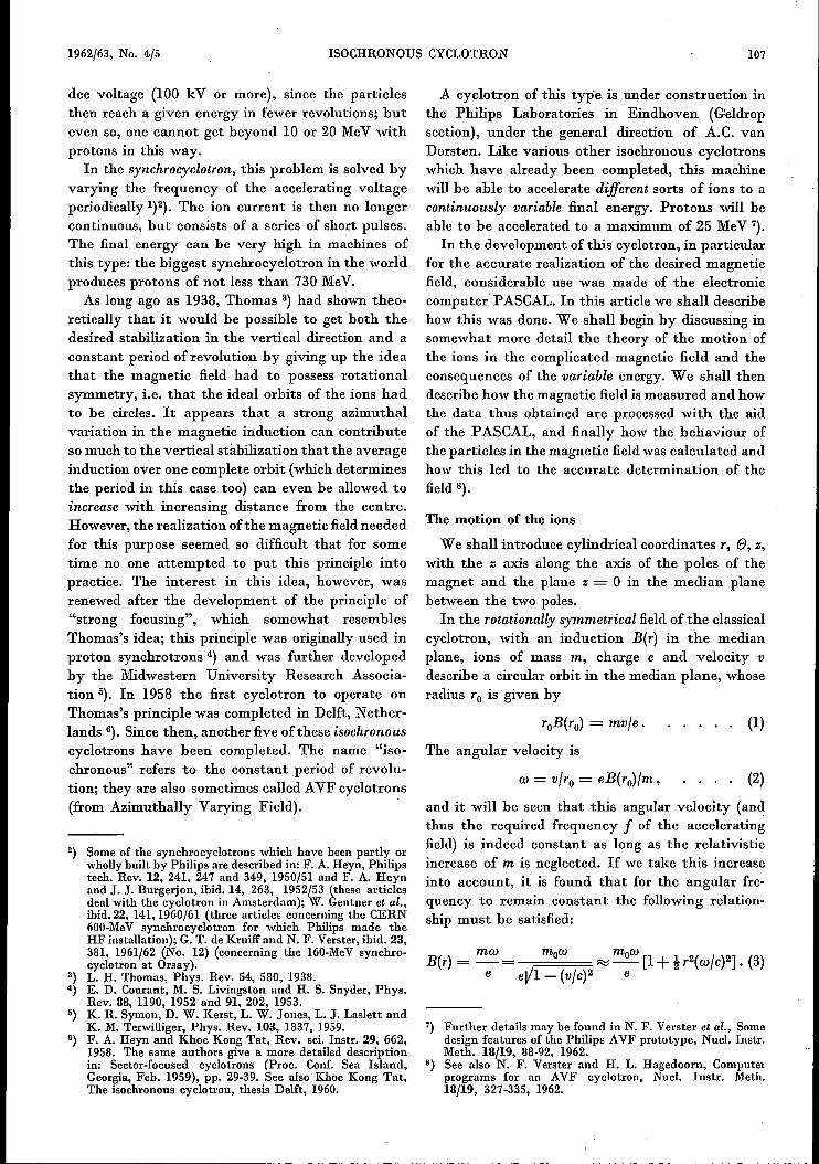
106 PHILIPS TECHNICAL REVIEW VOLUME 24 INVESTIGATION OF THE MAGNETIC FIELD OF AN ISOCHRONOUS CYCLOTRON by N. F. VERSTER *) and H. L. HAGEDOORN *). The invention of the cyclotron by Lawrence was based on the fact that a homogeneous magnetic field forces ions of a given mass to describe circular orbits with a constant period, independent of their velocity. The ions can therefore be given greater and greater velocities with the aid of an HF alternating electric field (applied across the slit between the two "Dees") (fig. 1). The factor limiting the velocity which can be attained in this way has already been men- tioned several times in this journal I}: as the energy of the ions increases, the relativistic increase of their mass begins to be appreciable; for protons, this in- crease amounts to 1% per 10 MeV. In order to keep the period of revolution of the ions constant despite this fact, the magnetic field would have to increase slightly with increasing distance from the centre. It is found in practice however that the magnetic field must actually decrease slightly with increasing distance from the centre. This is because the ions can oscillate vertically and horizontally about their ideal (horizontal) orbit, and the magnetic field should be slightly barrel-shaped in order to stabilize the vertical oscillation, which implies that the field should decrease with increasing distance from the centre. Since the period of revolution of the ions is *) Philips Research Laboratories, Eindhoven. 1) For example, W. de Groat, Cyclotron and synchrocyclotron, Philips tech. Rev. 12, 65-72, 1950/51. 621.317.42:621.384.611.2 thus not constant, the particles do not always pass the slit at the moment when the electric field has its maximum accelerating value (phase 0°), but are gradually retarded. When the phase lag reaches 90°, the ions are no longer accelerated at all. This effect can be reduced to a certain extent by using a high Fig. 1. Principle of the acceleration of ions in a cyclotron. The ions supplied by the source S are accelerated in the electric field between the two D-shaped electrodes D (the "dees"), They describe circular orbits under the influence of a magnetic field (perpendicular to the plane of the paper), so that they keep on passing the slit between the dees. The vol tage applied between the dees is AC of such a frequency that the field between the dees just reverses in the time which it takes the ions to describe half a circle. P is the edge of one of the poles of the magnet.
Transcript of INVESTIGATION OF THE MAGNETIC FIELD OFAN ISOCHRONOUS CYCLOTRON Bound... · 106 PHILIPS TECHNICAL...
106 PHILIPS TECHNICAL REVIEW VOLUME 24
INVESTIGATION OF THE MAGNETIC FIELD OF AN ISOCHRONOUS CYCLOTRON
by N. F. VERSTER *) and H. L. HAGEDOORN *).
The invention of the cyclotron by Lawrence wasbased on the fact that a homogeneous magnetic fieldforces ions of a given mass to describe circular orbitswith a constant period, independent of their velocity.The ions can therefore be given greater and greatervelocities with the aid of an HF alternating electricfield (applied across the slit between the two "Dees")(fig. 1). The factor limiting the velocity whichcan be attained in this way has already been men-tioned several times in this journal I}: as the energyof the ions increases, the relativistic increase of theirmass begins to be appreciable; for protons, this in-crease amounts to 1% per 10 MeV. In order to keepthe period of revolution of the ions constant despitethis fact, the magnetic field would have to increaseslightly with increasing distance from the centre.It is found in practice however that the magneticfield must actually decrease slightly with increasingdistance from the centre. This is because the ionscan oscillate vertically and horizontally about theirideal (horizontal) orbit, and the magnetic field shouldbe slightly barrel-shaped in order to stabilize thevertical oscillation, which implies that the fieldshould decrease with increasing distance from thecentre. Since the period of revolution of the ions is
*) Philips Research Laboratories, Eindhoven.1) For example, W. de Groat, Cyclotron and synchrocyclotron,
Philips tech. Rev. 12, 65-72, 1950/51.
621.317.42:621.384.611.2
thus not constant, the particles do not always passthe slit at the moment when the electric field hasits maximum accelerating value (phase 0°), but aregradually retarded. When the phase lag reaches 90°,the ions are no longer accelerated at all. This effectcan be reduced to a certain extent by using a high
Fig. 1. Principle of the acceleration of ions in a cyclotron. Theions supplied by the source S are accelerated in the electricfield between the two D-shaped electrodes D (the "dees"),They describe circular orbits under the influence of a magneticfield (perpendicular to the plane of the paper), so that they keepon passing the slit between the dees. The vol tage applied betweenthe dees is AC of such a frequency that the field between thedees just reverses in the time which it takes the ions to describehalf a circle. P is the edge of one of the poles of the magnet.
1962/63, No. 4/5 ISOCHRONOUS CYCLOTRON 107
dee voltage (100 kV or more), since the particlesthen reach a given energy in fewer revolutions; buteven so, one cannot get beyond 10 or 20 MeV withprotons in this way.
In the synchrocyclotron, this problem is solved byvarying the frequency of the accelerating voltageperiodically 1)2). The ion current is then no longercontinuous, but consists of a series of short pulses.The final energy can he very high in machines ofthis type: the biggest synchrocyclotron in the worldproduces protons of not less than 730 MeV.
As long ago as 1938, Thomas 3) had shown theo-retically that it would be possible to get both thedesired stabilization in the vertical direction and aconstant period of revolution by giving up the ideathat the magnetic field had to possess rotationalsymmetry, i.e. that the ideal orbits of the ions hadto be circles. It appears that a strong azimuthalvariation in the magnetic induction can contributeso much to the vertical stabilization that the averageinduction over one complete orbit (which determinesthe period in this case too) can even be allowed toincrease with increasing distance from the centre.However, the realization of the magnetic fieldneededfor this purpose seemed so difficult that for sometime no one attempted to put this principle intopractice. The interest in this idea, however, wasrenewed after the development of the principle of"strong focusing", which somewhat resemblesThomas's idea; this principle was originally used inproton synchrotrons 4) and was further developedby the Midwestern University Research Associa-tion 5). In 1958 the first cyclotron to operate onThomas's principle was completed in Delft, Nether-lands 6). Since then, another five of these isochronouscyclotrons have been completed. The name "iso-chronous" refers to the constant period of revolu-tion; they are also sometimes called AVF cyclotrons(from Azimuthally Varying Field).
2) Some of the synchrocyclotrons which have been partly orwholly built by Philips are described in: F. A. Heyn, Philipstech. Rev. 12, 241, 247 and 349, 1950/51 and F. A. Heynand J. J. Burgerjon, ibid. 14, 263, 1952/53 (these articlesdeal with the cyclotron in Amsterdam); W. Gentner et al.,ibid.22, 141,1960/61 (three articles concerning the CERN600-MeV synchrocyclotron for which Philips made theHF installation); G. T. de Kruiff and N. F. Verster, ibid. 23,381, 1961/62 (No. 12) (concerning the 160-MeVsynchro-cyclotron at Orsay).
3) L. H. Thomas, Phys. Rev. 54, 580, 1938.4) E. D. Courant, M. S. Livingston and H. S. Snyder, Phys.
Rev. 88, 1190, 1952 and 91, 202, 1953.5) K. R. Symon, D. W. Kerst, L. W. Jones, L. J. Laslett and
K. M. Terwilliger, Phys. Rev. 103, 1837, 1959.B) F. A. Heyn and Khoe Kong Tat, Rev. sci. Instr. 29, 662,
1958. The same authors give a more detailed descriptionin: Sector-focused cyclotrons (Proc. Conf. Sea Island,Georgia, Feb. 1959), pp. 29-39. See also Khoe Kong Tat,The isochronous cyclotron, thesis Delft, 1960.
A cyclotron of this typ-e is under construction inthe Philips Laboratories in Eindhoven (Geldropsection), under the general direction of A.C. vanDorsten. Like various other isochronous cyclotronswhich have already been completed, this machinewill be able to accelerate different sorts of ions to acontinuously variable final energy. Protons will beable to be accelerated to a maximum of 25 MeV 7).In the development of this cyclotron, in particular
for the accurate realization of the desired magneticfield, considerable use was made of the electroniccomputer' PASCAL. In this article we shall describehow this was done. We shall begin by discussing insomewhat more detail the theory of the motion ofthe ions in the complicated magnetic field and theconsequences of the variable energy. We shall thendescribe how the magnetic field is measured and howthe data thus obtained are processed with the aidof the PASCAL, and finally how the behaviour ofthe particles in the magnetic field was calculated andhow this led to the accurate determination of thefield 8).
The motion of the ions
We shall introduce cylindrical coordinates r, e, z,with the z axis along the axis of the poles of themagnet and the plane z = 0 in the median planebetween the two poles.
In the rotationally symmetrical field of the classicalcyclotron, with an induction B(r) in the medianplane, ions of mass m, charge e and velocity vdescribe a circular orbit in the median plane, whoseradius r0 is given by
(1)
The angular velocity is
w = vJro = eB(ro)Jm, (2)
and it will be seen that this angular velocity (andthus the required frequency f of the acceleratingfield) is indeed constant as long as the relativisticincrease of m is neglected. If we take this increaseinto account, it is found that for the angular fre-quency to remain constant the following relation-ship must be satisfied:
mw mow mowB(r) = -= ~-[I+tr2(wJc)2]. (3)
e eVI - (VJC)2 e
7) Further details may be found in N. F. Verster et al., Somedesign features of the Philips AVF prototype, Nucl, Instr.Meth. 18/19, 88-92, 1962.
8) See also N. F. Verster and H. L. Hagedoorn, Computerprograms for an AVF cyclotron, Nucl. Instr. Meth.18/19, 327-335, 1962.
108 PHILlPS TECHNICAL REVIEW VOLUME 24
This is known as the isochronous :field form, and weshall denote it by Bis(r) from now on. The fre-quency fz of the vertical oscillations of the ionsabout the circle of radius ro (the equilibrium orbit)is given by 9)
(fzlf)2 = -k ,
where k is the "field index", defined by the equation
k = !_ _dB_ = -::d,.."lo_:gc_B_B dr d log r
For stability in the vertical direction, it is necessarythat fz should be real, i.e. that k should be negative.This makes it impossible to satisfy equation (3),which is thus the reason why the rotationally sym-metrical magnetic :fieldis useless when the relativistic.increase of mass becomes appreciable.
The frequency fr of the radial oscillations is givenby:
{fr/f)2 = 1+ k.
Radial stability is thus achieved as long as k > -1.If we now abandon the idea of a rotationally
symmetrical magnetic field, as Thomas suggested,then the form of the magnetic field in the medianplane z = 0 can be described quite generally bymeans of a Fourier series:
or
We cannot discuss the theory of the motion of theions in such a field in great detail here. In the firstplace, this theory states that radial stability is onlypossible if the first two harmonics are absent or atleast very weak (Cl «10-3 and C2 «10-2). In orderto satisfy this condition, the magnetic field is giventhree-fold or four-fold symmetry about the z axis.Equation (6) then only contains terms inwhich n isa multiple of 3 (thus 3, 6, 9, ... ) or 4 (thus 4, 8,12, ... ). Three-fold symmetry was chosen for ourcyclotron, and we shall therefore restrict ourselvesto this case, where n = 3 is the lowest occurringterm (and the most important).
.0) This formula follows directly from the equations of motionof the ion. See e.g. 1) or p. 386 of the last article quotedin 2). Wc may mention that in these articles the definitionof the field index n differs from that used here: n= -k.
(4.)
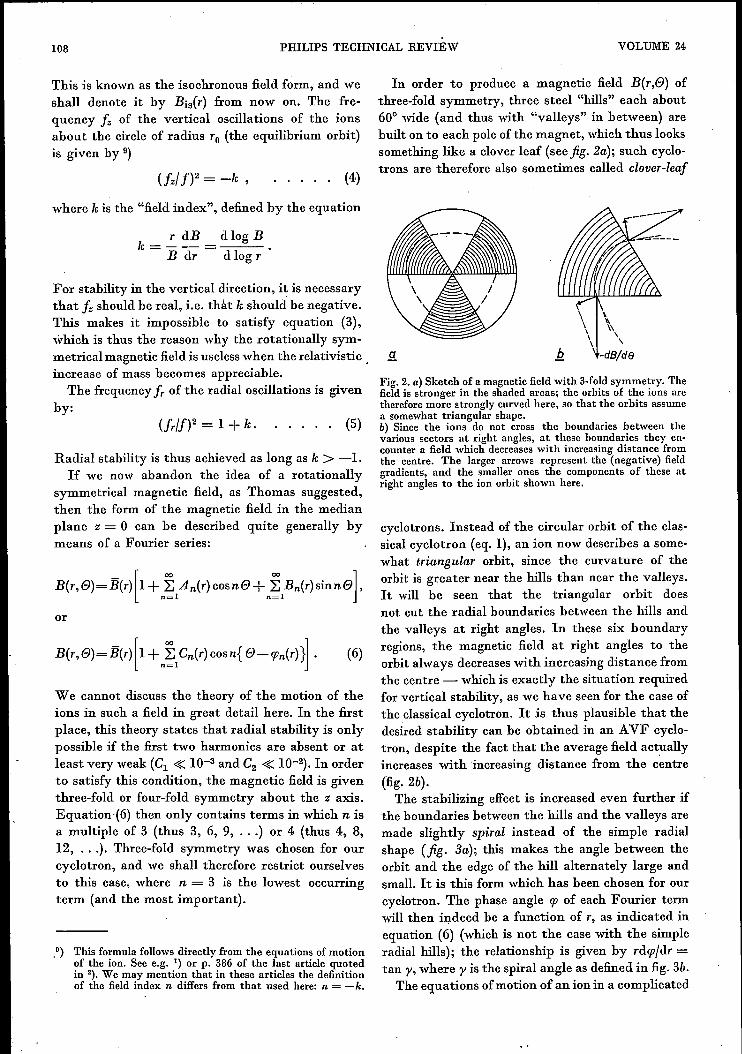
In order to produce a magnetic field B(r,e) ofthree-fold symmetry, three steel "hills" each about60° wide (and thus with "valleys" in between) arebuilt on to each pole of the magnet, which thus lookssomething like a clover leaf (see jig. 2a); such cyclo-trons are therefore also sometimes called clover-leaf
\
\ "\ '\\ \
i1. \ -dB/de
(5)
Fig. 2. a) Sketch of a magnetic fieldwith 3-foldsymmetry. Thefield is stronger in the shaded areas; the orbits of the ions aretherefore more strongly curved here, so that the orbits assumea somewhat triangular shape.b) Since the ions do not cross the boundaries between thevarious sectors at right angles, at these boundaries they en-counter a field which decreaseswith increasing distance fromthe centre. The larger arrows represent the (negative) fieldgradients, and the smaller ones the components of these atright angles to the ion orbit shown here.
cyclotrons. Instead of the circular orbit of the clas-sical cyclotron (eq. 1), an ion now describes a some-what triangular orbit, since the curvature of theorbit is greater near the hills than near the valleys.It will be seen that the triangular orbit doesnot cut the radial boundaries between the hills andthe valleys at right angles. In these six boundaryregions, the magnetic field at right angles to theorbit always decreases with increasing distance fromthe centre - which is exactly the situation requiredfor vertical stability, as we have seen for the case ofthe classical cyclotron. It is thus plausible that thedesired stability can be obtained in an AVF cyclo-tron, despite the fact that the average field actuallyincreases with increasing distance from the centre(fig. 2b).The stabilizing effect is increased even further if
the boundaries between the hills and the valleys aremade slightly spiral instead of the simple radialshape (jig. 3a); this makes the angle between theorbit and the edge of the hill alternately large andsmall. It is this form which has been chosen for ourcyclotron. The phase angle rp of each Fourier termwill then indeed be a function of r, as indicated inequation (6) (which is not the case with the simpleradial hills); the relationship is given by rdrp/dr =tan y, where y is the spiral angle as defined in fig. 3b.
The equations of motion of an ion in a complicated
1962/63, No. 4/5 ISOCHRONOUS CYCLOTRON 109
field, as described by equation (6), cannot be solvedexactly. This is one of the greatest problems en-countered by the designer of an isochronous cyclo-tron. Here too, the electronic computer provides thesolution to the problem: the orbits were determinedby numerical analysis, with the aid of the PASCAL.The functions B(r), Aa(r), Ba(r), A6(r), Bir), ... ,which are needed for this calculation, were in theirturn calculated by the PASCAL from measurementsof the magnetic field (Fourier analysis). Because ofthe three-fold symmetry, it is only necessary to makemeasurements in one 1200 sector, along a number ofarcs of circles of different radii. (A number of checkmeasurements were made through 3600 to make surethat the amplitudes of the first and second harmonicswere indeed as small as specified above.) The requiredisochronous field distribution Bis(r), the correspond-ing angular velocity w, and the oscillation fre-quencies fz and fr were then determined from thesecalculated orbits, again with the aid ofthe PASCAL.When we speak here of "the" magnetic field which
is measured and for which the ion orbits are cal-culated, we mean in the first place an actual fieldobtained using clover-leaf poles. The results of thecalculations are naturally just what is needed todetermine the corrections which must be made to thefield to ensure exact isochrony. We shall discuss thisin more detail in the next section.
The calculations in question, which we shall alsodiscuss further below, are rather complicated andtime-consuming, even with the PASCAL. We havetherefore also paid some attention to the possibilityof designing a cyclotron using an approximateanalytical solution of the equations of motion in theclover-leaf magnetic field. The simplifying assump-tions which are necessary in order to obtain a solu-tion in this way are however so drastic that it seemeddoubtful whether the solution thus obtained wouldbe of any practical use. Moreover, the expressions
Fig. 3. Sketch of an azimuthally varying field of 3-fold sym-metry, with sectors bounded by spirals. a) Overall view of thefield. b) The angle y of the spiral at the point A of the spiralsector boundary is thê angle between the radius OA and thetangent at A.
for the isochronous field, the angular velocity and f(and fr) are still very complicated 10). We will givehere only the most important terms in these ex-pressions:
eB [ ( dCa2))w ~ - 1+ to Cl + i2 r-- ,m dr
(7b)
(8)
We have (again with the aid ofthe PASCAL) com-puted the value of the complete expressions in allcases, using the above-mentioned functions Aa, Ba,A6, B6, • •• obtained from the Fourier analysis ofthe magnetic field. The values thus found agree verywell with the values previously calculated withoutmaking any simplifying assumptions, so it wouldseem to be justified to use the above-mentionedexpressions in further projects.
. .The stabilizing effect of the clover-leaf field, which we
postulated on the basis of general arguments above, is givenquantitative expression in equation (8): even if the field indexis positive (field increasing with increasing distance' from thecentre), vertical stability is still possible as long as the coeffi-cient Ca is large enough, and the spiral shape of the sectorboundaries (y > 0) also helps in this direction.In order to give some idea of the values found in practice,
we may mention that the maximum fieldindex of our clover-leaf cyclotron is +0.05. Further, Ca ~ 0.3 and y = 35°,from which (f./f)2 = +0.04.
Variation of the final energy of the ions
If it is desired to bring the beam of high-energyions produced in a cyclotron out of the acceleratingspace (which is the case in most nuclear physicalexperiments), then a beam-extraction system mustbe introduced into the magnetic field 11). Ions withlower energies than the maximum are in principleavailable in orbits with smaller radii, but in practiceit is not possible to extract them by shifting theextraction system towards the middle of the cyclo-tron. In order to vary the energy of the ions, whichis desirable for many investigations, one must there-fore extract the ions from the same orbit .and vary-the induction B, i.e. alter the current flowing throughthe energizing .coils of the magnet.
10) The equations of motion and the approximate analyticalsolutions referred to here may be found in H. L. Hagedoornand N. F. Verster, Orbits in an AVF cyclotron, Nucl. Instr.Meth. 18/19, 201-228, 1962.
11) The design of a magnetic beam-extraction system for asynchrocyclotron has recently been described in this Reviewin the last article quoted in 2).
110 PHILIPS TECHNICAL REVIEW VOLUME 24
1
bevelled so as to preventstrong field concentrationat the edges and thus tolimit saturation as much aspossible, this effect is stillnoticeable. However, thisdoes not matter as muchas might be thought, sincefor other reasons the givenfield distribution B(r) canno longer be used whenanother final energy is re-quired. This has nothingto do with the stability ofthe orbits - the Fouriercoefficients An(r) and Bn(r)usually remain large enoughto ensure vertical stability,even if they have been alteredby the saturation effect -but with the isochronism.
This is because when theIOn energy on the fixedouter circle is altered, thefield distribution needed forisochronism changes SIncethe relativistic increase ofmass IS now a differentfunction of the radius. (Thisis the third and most im-portant consequence.) Thesame applies if we wantto accelerate different kindsof particles (e.g. deuteronsand a particles as well asprotons). In our cyclotron,we can accelerate protons to25 MeV with an inductionon the axis ofBo=1.4 Wb/m2;the mean induction at theperiphery must then be 0.037
Wb/m2 more, because of the increase ofmass of2.5 %.With the same value of Bo, deuterons are acceleratedto 12.5MeV, the increase of mass is then about 0.6%,and the mean induction at the periphery need nowonly be about 0.009 Wb/m2 greater than Bo. Inorder to realize the desired isochronous field for each
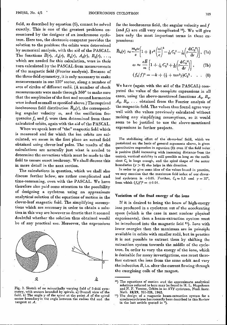
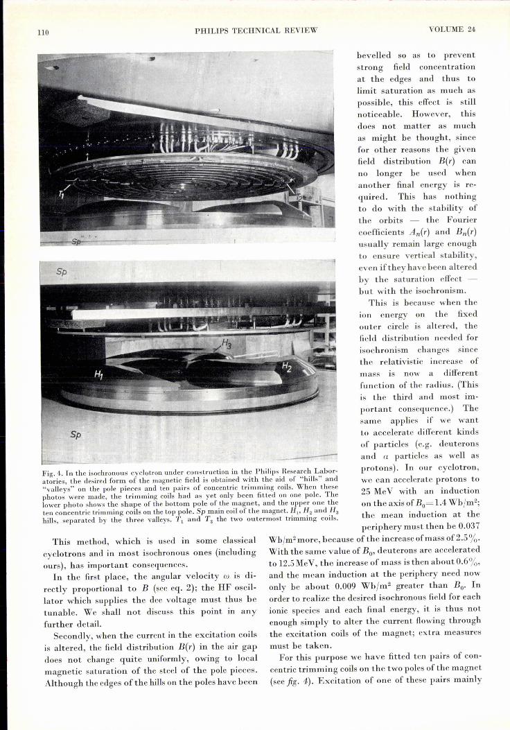
Fig. 4. In the isochronous cyclotron under construction in the Philips Research Labor-atories, the desired form of the magnetic field is obtained with the aid of "hills" and"valleys" on the pole pieces and ten pairs of concentric trimming coils. When thesephotos were made, the trimming coils had as yet only been fitted on one pole. Thelower photo shows the shape of the bottom pole of the magnet, and the upper one theten concentric trimming coils on the top pole. Sp main coil of the magnet. H" Hz and H3hills, separated by the three valleys. Tl and T2 the two outermost trimming coils.
This method, which is used in some classicalcyclotrons and in most isochronous ones (includingours), has important consequences.
In the first place, the angular velocity w is di-rectly proportional to B (see eq. 2); the HF oscil-lator which supplies the dee voltage must thus betunable. We shall not discuss this point in anyfurther detail.
Secondly, when the current in the excitation coilsis altered, the field distribution B(r) in the air gapdoes not change quite uniformly, owing to localmagnetic saturation of the steel of the pole pieces.Although the edges ofthe hills on the poles have been
ionic species and each final energy, it is thus notenough simply to alter the current flowing throughthe excitation coils of the magnet; extra measuresmust be taken.
For this purpose we have fitted ten pairs of con-centric trimming coils on the two poles of the magnet(see fig. 4). Excitation of one of these pairs mainly
1962/63, No. 4/5 ISOCHRONOUS CYCLOTRON 111
effects B(r) for values of r lower than the radius ofthe coil. The largest coil causes Bo to change byabout 0.025 Wbjm2• Each of these ten pairs of coils(and the main coil itself) must now be activated inan appropriate manner for each desired ionic speciesand each final energy. This kills two birds with onestone, since changes in the magnetic saturation ofthe magnet steel are also compensated for. Thedetermination of the excitation currents is in factthe main problem treated in this article.
It should be mentioned in this connection that avery great accuracy is demanded for this purpose.Even though we have chosen the relatively highvalue of 50 kV for the dee voltage, a proton still hasto make 250 revolutions to reach an energy of25 MeV. Let us suppose that we have chosen B(r)only 0.1% less than the required isochronous fieldthroughout; the ion would then undergo a phase lagof 0.36° with respect to the dee voltage each revo-lution, and after 250 revolutions the phase lag wouldbe 90°. It is thus clear that the isochronous field mustbe realized with an accuracy of considerably betterthan 1 part in a 1000.
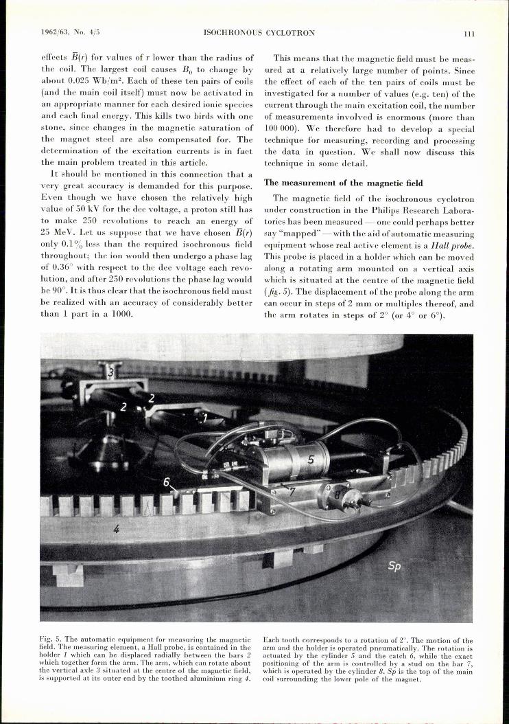
Fig. 5. The automatic equipment for measuring the magneticfield. The measuring element, a Hall probe, is contained in theholder 1 which can be displaced radially between the bars 2which together form the arm. The arm, which can rotate aboutthe vertical axle 3 situated at the centre of the magnetic field,is supported at its outer end by the toothed aluminium ring 4.
This means that the magnetic fieldmust be meas-ured at a relatively large number of points. Sincethe effect of each of the ten pairs of coils must beinvestigated for a number of values (e.g. ten) of thecurrent through the main excitation coil, the numberof measurements involved is enormous (more than100000). We therefore had to develop a specialtechnique for measuring, recording and processingthe data in question. We shall now discuss thistechnique in some detail.
The measurement of the magnetic field
The magnetic field of the isochronous cyclotronunder construction in the Philips Research Labora-tories has been measured - one could perhaps bettersay "mapped" - with the aid of automatic measuringequipment whose real active element is a Hall probe.This probe is placed in a holder which can be movedalong a rotating arm mounted on a vertical axiswhich is situated at the centre of the magnetic field(fig· 5). The displacement ofthe probe along the armcan occur in steps of 2 mm or multiples thereof, andthe arm rotates in steps of 2° (or 4° or 6°).
Each tooth corresponds to a rotation of 2°. The motion of thearm and the holder is operated pneumatically. The rotation isactuated by the cylinder 5 and the catch 6, while the exactpositioning of the arm is controlled by a stud on the bar 7,which is operated by the cylinder 8. Sp is the top of the maincoil surrounding the lower pole of the magnet.
112 PHILlPS TECHNICAL REVIEW VOLUME 24
Since we wanted to measure the :fieldwith an ac-curacy of about 1X 10⁻⁴ Wb/m2 (1 gauss) and as the:fieldgradient at the edges of the sectors is very large,the position of the Hall probe had to be accurate towithin about 0.05 mm. The azimuthal position ofthearm is accurate to within 12 seconds of areowing to the use of a toothed ring round the edge ofthe magnet, on which the arm rests. The requiredprecision of the displacement of the holder along thearm was obtained with the aid of a perforated bronzestrip.
The displacement ofthe Hall probe is produced bymeans of compressed air. This method lends itselfboth to automation and to operation in a magnetic:field. The equipment allows a measurement to becarried out every 5 seconds. The course of each5-second cycle is determined by a rotary switch. Itis possible to carry out measurements along thecircumference of a circle (r = constant), and alsoalong a given radius (e = constant). A similar, butsmaller and simpler, device was constructed formeasurements on a model magnet (scaled down5 times) to determine the best shape of the hills andvalleys in the poles of the magnet.
The Hall probe was fed with a current of 18 mA.The sensitivity at this current is about 3X 10⁻²
Vm2/Wb (= 3 fLVper gauss). The DC voltage thusobtained was ampli:fied 300 times using a chopperampli:fier, with a very constant ampli:fication factor(1 : 104), owing to strong negative feedback (5000X ).The noise in the output signal corresponds to about1 fLV, so a difference in induction of 1X 10⁻⁴ Wb/m2
is easily detected.Also in the interests of precision, the current
supply of the Hall probe is kept very constant (betterthan 1 in 3X 10⁴), and the probe itself is kept in asmall thermostat.
The Hall probe was calibrated by placing it,together with the measuring probe of a proton-resonance set-up, in the :field of an. auxiliarymagnet 12). This :field was then so adjusted thatnuclear magnetic resonance occurred at 4 Mc/s and atall harmonics ofit up to the 21st (i.e. up to 84 Mc/s).The inductions corresponding to the lowest andhighest frequencies are 0.0940 and 1.9738 Wb/m2
respectively. By working with a series ofharmonics,we were independent of the quality of the standardoscillator as regards linearity. This procedure gave22 calibration points (including that for zero :field).
The relationship between the induction and theoutput voltage of the Hall probe is linear to within
12)The measurement of magnetic fields by means of the nuclearmagnetic resonance of protons is described in e.g, Philipstech. Rev. 15, 55, 1953/54.
about 1%, but because of the great precIsIOn re-quired it was necessary to represent it by a seventh-degree polynomial. Regular checks of the outputvoltage at the highest resonance frequency (84 Mc/s)have shown that the apparatus is very stable: onlysmall and infrequent corrections were necessary.This correction is made by varying the currentthrough the Hall probe until the output voltagereturns to its original value. The deviation in theoutput voltage at lower frequencies then correspondsto less than 1 X 10⁻⁴ Wb/m2. Fig. 6 gives an idea ofthe variation in the measured values due to randomfluctuations ("noise").
The ampli:fied output signalof the Hall probe isfed to a digital voltmeter with a capacity of fourdigits and a sensitivity of 1 mV per unit. The equip-ment is so adjusted that this meter reads -9995 inthe absence of a magnetic :field and +9995 at aninduction of 2.0000 Wb/m2: one unit thus corre-sponds very nearly to 1X 10⁻⁴ Wb/m2. The readingof this meter is automatically typed out, and alsopunched in 5-channel telex tape, the latter formbeing suitable for feeding into a computer. Fig. 7gives an impression of the equipment during meas-urements on the model magnet.
._-"""""=='=="'=---=--=+ .50
------~------------------424(}------------------------~OL-__~ ___L __ ~ L_ __ ~ __ -L __ ~
1,2 1,3 1,4 1,5Wb/m2
--+8(0)
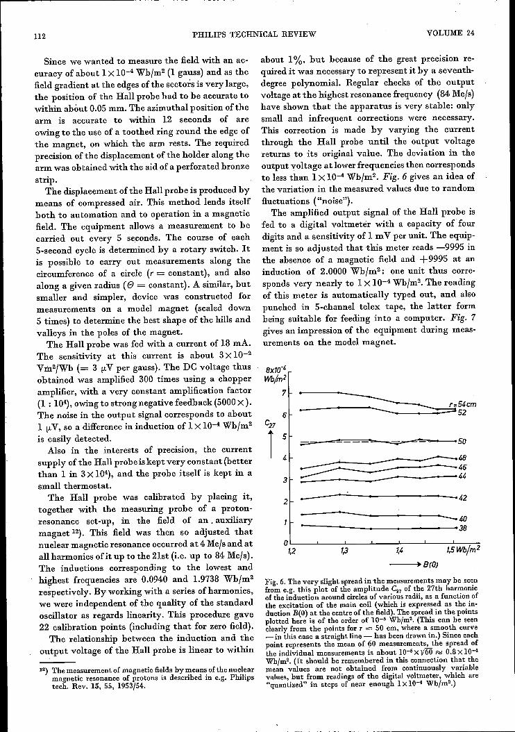
Fig. 6.The very slight spread in the measurements may be seenfrom e.g. this plot of the amplitude C27 of the 27th harmonicof the induction around circles of various radii, as a function ofthe excitation of the main coil (which is expressed as the in-duction B(O) at the centre of the field). The spread in the pointsplotted here is of the order of 10-5 Wb/m2• (This can be seenclearly from the points for T = 50 cm, where a smooth curve_ in this case a straight line - has been drawn in.) Since eachpoint represents the mean of ~Omeasurements, the spread ofthe individual measurements is about 10-5 Xy60 Ri 0.8 X10⁻⁴Wb/m2. (It should be remembered in this connection that themean values are not obtained from continuously variablevalues, but from readings of the digital voltmeter, which are"quantized" in steps of near enough 1X10⁻⁴ Wb/m2.)
1962/63, No. 4./5 ISOCHRONOUS CYCLOTRON 113
Phot o Adolf Morath
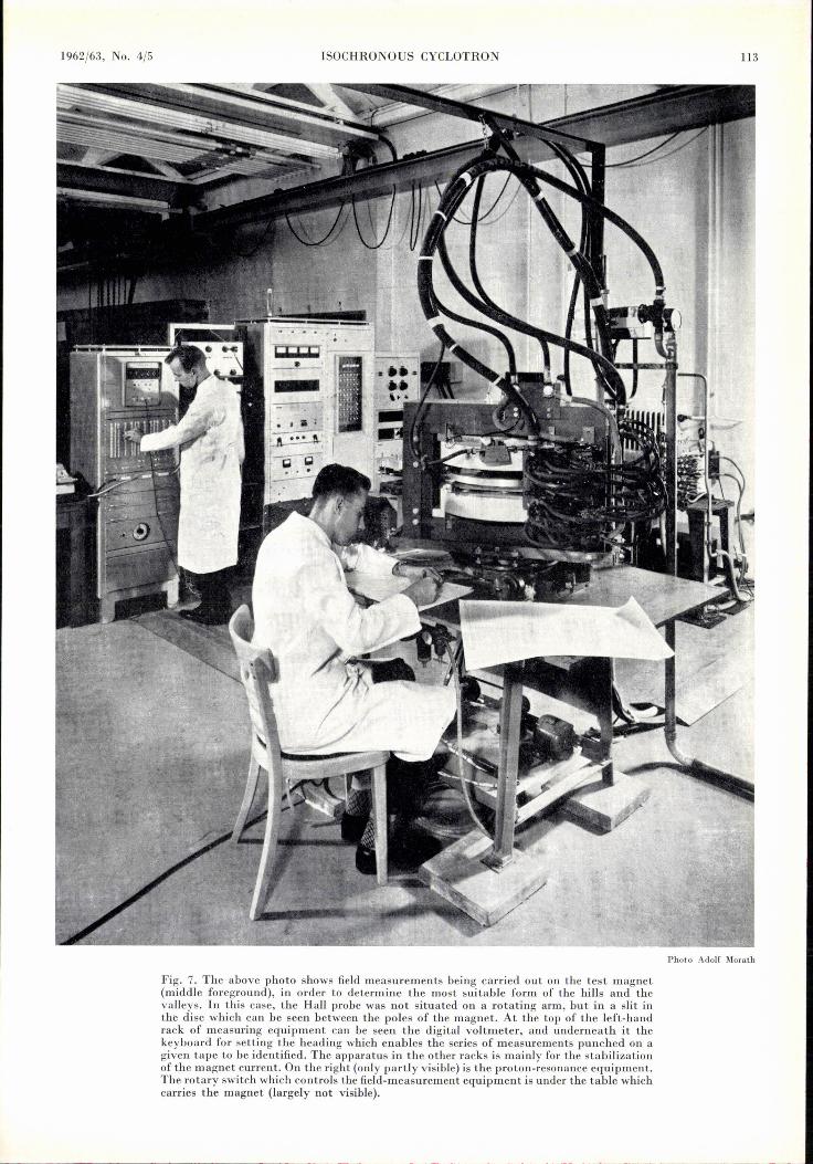
Fig. 7. The above photo shows field measurements being carried out on the test magnet(middle foreground), in order to determine the most suitable form of the hills and thevalleys. In this case, the Hall probe was not situated on a rotating arm, but in a slit inthe disc which can be seen between the poles of the magnet. At the top of the left-handrack of measuring equipment can be seen the digital voltmeter, and underneath it thekeyboard for setting the heading which enables the series of measurements punched on agiven tape to be identified. The apparatus in the other racks is mainly for the stabilizationof the magnet current. On the right (only partly visible) is the proton-resonance equipment.The rotary switch which controls the field-measurement equipment is under the table whichcarries the magnet (largely not visible).
114 PHILIPS TECHNICAL REVIEW VOLUME 24
The investigation of this model magnet (scaled down 5 times)was necessary because it is impossible to calculate the requiredform of the hills and valleys exactly. The form which gives thebest results must be found by trial and error, by finding howdifferent variables change with different shapes of the polepieces and then trying to interpolate to the best shape. Fairlyrough models can be used to begin with, but the finalones musthave a precision of at least 1 in 103• Naturally, the quality ofthe steel used for the model magnet, and the indnction, mustcorrespond to that intended for use in the cyclotron itself. Thepower consumption of the coil of our model magnet was there-fore no less than 25 kW.
The identification of a measurement and the detectionof errors
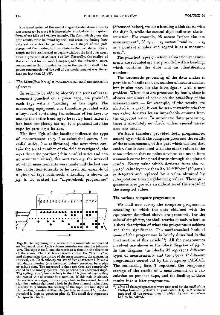
In order to be able to identify the series of meas-urements punched on a given tape, we providedeach tape with a "heading" of ten digits. Themeasuring equipment was therefore provided witha key-board containing ten columns of ten keys, toenable the entire heading to he set by hand. After ithas been completely set up, it is punched into thetape by pressing a button.
The first digit of the heading indicates the typeof measurement (e.g. 2 = azimuthal series, 5 =radial series, 9 = calibration), the next three con-tain the serial number of the field investigated, thenext three the position (g in a radial series and r inan azimuthal series), the next two e.g. the intervalat which measurements were made and the last onethe calibration formula to be used. An example ofa piece of tape with such a heading is shown infig. 8. To control the "input-check programme"
b ba
•••••••••••••••••••• ••......................••••• •
• •• • ' .• •••••••
•
Fig. 8. The beginning of a series of measurements as punchedon 5-channel tape. Each column contains one number (charac-ter). The tape is read, one character at a time, in the directionof the arrow. The first ten characters form the "heading" a,and characterize the nature of the measurement, the measuringinterval, etc. Each subsequent set of five characters b forms afour-figure number (one measured value), preceded by a plusor minus sign. The measured values are thus not completelycoded in the binary system, but punched per (decimal) digit.The coding is as follows. A hole in the fifth channel means thatthe rest of this character is a number. If this hole is absent,the rest is a code sign; for example, a hole in the second channelsignifies a minus sign, and a hole in the first channel a plus sign.In order to facilitate the reading of the tape; the first digit ofthe heading is coded differently (no hole in channel 5; numberpunched is digit in question plus 3). The small dots representthe sprocket holes.
(discussed below), we use a heading which starts withthe digit 0, while the second digit indicates the in-struction. For example, 08 means "reject thè lastmeasurement", 05 Xl ••• Xs means "read Xl ••• Xs
as a positive number and regard it as a measure-ment".
The punched tapes on which calibration measure-ments are recorded are also provided with a heading,which contains the date and an identificationnumber.
The automatic processing of the data makes itpossible to handle the vast number of measurements,but it also provides the investigator with a newproblem. When data are processed by hand, there isalways some sort of check on the reliability of themeasurements - for example, if the results areplotted in a graph it can be seen instantly whetherone value deviates by an improbable amount fromthe expected value. In automatic data processing,there is absolutely no check unless special meas-ures are taken.
We have therefore provided both programmes,according to which the computer processes the resultsof the measurements, with a part which ensures thateach value is compared with the other values in thesame series so that no point deviates too much froma smooth curve imagined drawn through the plottedresults. Every value which deviates from the ex-pected value by more than 2X 10⁻³ Wbfm2 (20 gauss)is detected and replaced by a value obtained byinterpolation from neighbouring values. These pro-grammes also provide an indication of the spread ofthe accepted values.
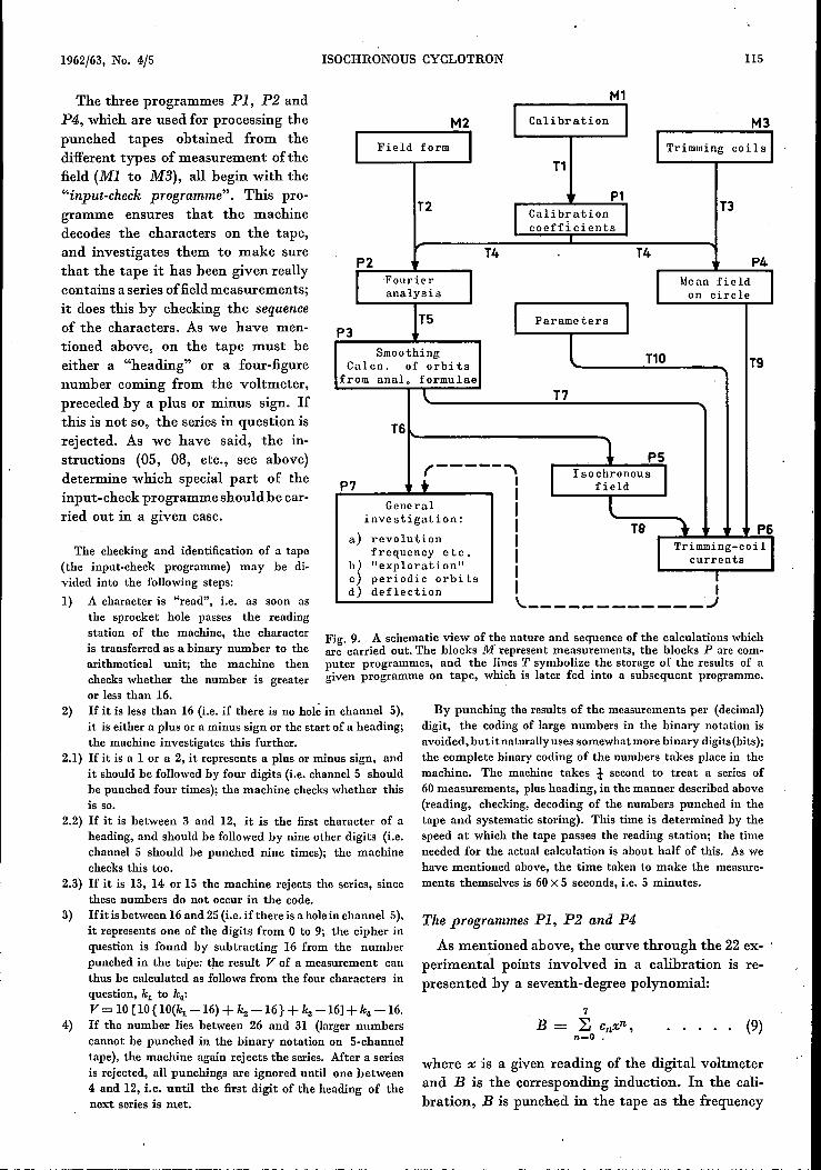
The various computer programmes
We shall now survey the computer programmesaccording to which the data obtained with theequipment described above are processed. For thesake of simplicity, we shall restrict ourselves here toa short description of what the programmes achieveand their significance. The mathematical basis ofsome of the programmes is briefly described in thefinal section of this article 13). All the programmesinvolved are shown in the block diagram of fig. 9.In this diagram, the blocks M represent differenttypes of measurements and the blocks P different'programmes carried out by the computer PASCAL.The connecting lines T represent the temporarystorage of the results of a measurement or a cal-culation on punched tape, and the feeding of theseresults into a later programme.13) Most of these programmes were prepared by the staff of the
Philips Computing Centre. In particular, H. Q. J.Meershoekprepared all the programmes in which the orbit equationshad to he solved.
1962/63, No. 4/5 ISOCHRONOUS CYCLOTRON 115
The three programmes PI, P2 andP4, which are used for processing thepunched tapes obtained from thedifferent types of measurement of thefield (MI to M3), all begin with the"input-check programme". This pro-gramme ensures that the machinedecodes the characters on the tape,and investigates them to make surethat the tape it has been given reallycontains a series of fieldmeasurements;it does this by checking the sequenceof the characters. As we have men-tioned above, on the tape must beeither a "heading" or a four-figurenumber coming from the voltmeter,preceded by a plus or minus sign. Ifthis is not so, the series in question isrejected. As we have said, the in-structions (05, 08, etc., see above)determine which special part of theinput- check programme should be car-ried out in a given case.
M1M2 ,
Calibration, M3, Field form
, ITrimming coi Is IT1
T2 P1 T3, Calibration -,coefficients
P2 T4 T4 P4I Fourier I I Mean field Ianalysis on circle
TS I Parameters 1P3Smoothing T10 TgCalcn. of orbi ts
from anal. formulae\. T7
T61 PSr-----""\
r Isochronous 1P7 .. I fieldIGeneral I l
investigation: I TB "\ P6a) revolution I I Trimming-coi 1 Ifrequency etc. I~~
"exploration" currentsperiodic orbits I I
d) deflection I I
The checking and identification of a tape(the input-check programme) may be di-vided into the following steps:1) A character is "read", î.e, as soon as
the sprocket hole passes the readingstation of the machine, the characteris transferred as a binary number to thearithmetical unit; the machine thencheckswhether the number is greateror less than 16.
2) If it is less than 16 (i.e. if there is no hol~in channelS),it is either a plus or a minus sign or the start of a heading;the machine investigates this further.
2.1) If it is a 1 or a 2, it represents a plus or minus sign, andit should be followedby four digits (i.e. channelS shouldhe punched four times); the machine checkswhether thisis so.
2.2) If it is between 3 and 12, it is the first character of aheading, and should be followedby nine other digits (i.e.channelS should be punched nine times); the machinechecks this too.
2.3) If it is 13, 14 or 15 the machine rejects the series, sincethese numbers do not occur in the code.
3) Ifitisbetween 16and 25(i.e. ifthere is aholein channelS),it represents one of the digits from 0 to 9; the cipher inquestion is found by subtracting 16 from the numberpunched in the tape: the result V of a measurement canthus be calculated as followsfrom the four characters inquestion, ~ to k4:V = 10[10{10(~ -16) + k2 -16} + ka -16] +k4-16.
4) If the number lies between 26 and 31 (larger numberscannot be punched in the binary notation on 5-channeltape), the machine again rejects the series. After a seriesis rejected, all punchings are ignored until one between4 and 12, i.e. until the first digit of the heading of thenext series is met.
\.. ..J
Fig. 9. A schematic view of the nature and sequence of the calculations whichare carried out. The blocks M represent measurements, the blocks P are com-puter programmes, and the lines T symbolize the storage of the results of agiven programme on tape, which is later fed into a subsequent programme.
By punching the results of the measurements per (decimal)digit, the coding of large numbers in the binary notation isavoided,butit naturallyuses somewhatmorebinary digits(bits);the complete binary coding of the numbers takes place in themachine. The machine takes i- second to treat a series of60measurements, plus heading, in the manner describedabove(reading, checking, decoding of the numbers punched in thetape and systematic storing). This time is determined by thespeed at which the tape passes the reading station; the timeneeded for the actual calculation is about half of this. As wehave mentioned above, the time taken to make the measure-ments themselves is 60X5 seconds, i.e. 5 minutes.
The programmes PI, P2 and P4
As mentioned above, the curve through the 22 ex-perimental points involved in a calibration is re-presented by a seventh-degree polynomial:
(9)
where x is a given reading of the digital voltmeterand B is the corresponding induction. In the cali-bration, B is punched in the tape as the frequency
116 PHILlPS TECHNICAL REVIEW VOLUME 24
of the proton resonance, and x as three readings ofthe voltmeter, i.e. each point on the calibrationcurve is obtained from three measurements: Theeight coefficients en are calculated with the aid ofprogramme PI by the method ofleast squares 14).
The programmes P2 and P4, which process theresults of measurements M2 and M3 respectively,. both start (after the input-check programme) witha part in which the measured :values are convertedinto values of B by use of eq. (9).
The rest ofthe programme P2 carries out a Fourieranalysis on all azimuthal series of measurements, (which extend, as we have mentioned, over one1200 sector). Since the sectors are assumed to beidentical, only those coefficients appear whose serialnumber is a multiple of three. These calculationsgive in the first place the quantities B, aam and bamwhich occur in the expression
~ .B(B) = B + ~ aam cos 3mB + bam sin 3mB. (10)
m=l
It will be seen that this is nothing more thanequation (6), expressed in a more suitable formfor our purposes.
The machine continues the Fourier analysis as faras the value M ofm at which a and b are of the sameorder of magnitude as the noise. (The values of aand b decrease rapidly with increasing m.)The machine is then instructed by P2 to check
whether there are any experimental values of Bwhich differ by more than 2 X lo-a Wbfm2 from thevalues calculated from equation (10), using theM pairs of Fourier coefficients which have just beenfound (Fourier synthesis). If such experimentalvalues are found, they are replaced by a value foundby interpolation. If the maximum deviation is stilltoo large after three such corrections, the wholeseries of measurements is rejected. The punchedtape TS which the machine delivers on completionof P2 contains B and the coefficients aam and bamfor m = 1 to 6; higher harmonics are neglected inthe further calculations. The printed paper whichthe machine delivers at the same time as TS gives,moreover, the maximum value of the differencebetween the measured values and the Fourier syn-thesis, as a measure of the noise involved in themeasurements.
The programme P4 processes the results of the
14) Descriptions of this method can be found both in chapterson regression analysis in text-books of statistics (e.g, P. G.Hoel, Introduetion to mathematical statistics, Wiley, NewYork 1954.or M. J. Moroney, Facts from figures, Penguinbooks 1951) and in books on experimental techniques inphysics (e.g. F. Kohlrausch, Praktische Physik, 20th edn.,Vol. 1, chap. 1.22, Teubner, Stuttgart 1955).
measurements on the ten pairs of trimming coils.In this case the main field is first measured, and thenthe field obtained when current flows through eachpair, of trimming coils in turn. Ten radial series cover-ing an entire 1200 sector are measured each time.Fluctuations of more than 2X lo-a Wbfm2l:_lreagaindetected and replaced by values obtained by radialinterpolation. The LlB(r) values for each pair of coilsare punched on tape (T9). The heading of this tapecontains among other things the serial number ofthe main'field and that of the pair of trimming coilsinvolved.
The programmes P3, PS and P6
With the aid of the programme P3 all resultsobtained with the aid of P2 which refer to oneparticular field (and which thus have the same fieldserial numberin their heading) are combined to givetables of B(r), a(r) and b(r). These series are also"smoothed" and any numbers which may bemissing are filled in by interpolation.
The following quantities are then calculated, usingthe above-mentioned approximate analytical solu-tion of the equations of motion:1) The frequencies of the horizontal and vertical
oscillations of an ion about its equilibrium orbit(neglecting the effect of the relativistic increasein mass).
2) The variation of B needed for isochronism (ditto).3) Two parameters which characterize the horizontal
stability 15).When these calculations are completed, the
machine punches two tapes. One (T6) contains the13 tables which give B(r), aam(r) and bam(r) forr = 0, 2, 4, ... , 70 cm. (One table of B(r) andtwelve of the Fourier coefficients.) The other tape(T7) contains only B(r). The tape T6 can be usedin the programmes in which the orbit equations haveto be integrated, while T7 is used in the programmeP6, for calculating the currents which must flowthrough the trimming coils in order to make themean field satisfy the conditions for isochrony.
The programme PS contains parts in which theorbit equations are integrated numerically, sotape T6 is made use ofhere. By means of an iterationprocess, which we shall not describe further, theequilibrium orbits are calculated for radii increasingfrom 4 to 54 cm, in steps of 2 cm. (Weshalldenote such a series by r = 4(2)54 cm.)
PS then calculates the form Bis of B(r) needed forisochronism, also by an iteration process. First of all,the angular velocity (J) is calculated for each of the
15) The parameters Dl and D2 of the article quoted in ~O).
1962/63, No. 4/5 ISOCHRONOUS CYCLOTRON 117
equilibrium orbits which have just been calculated.As in P3, the contribution of the relativistic increaseof mass is neglected; this is later inserted for eachionic species (each value of elm) separately. Since cvis roughly proportional to R, the corrections LIBwhich have to be applied to achieve isochronism canbe calculated with good accuracy from the corre-sponding values of zlro. Since this process convergesrapidly, it only needs to be repeated a few times toobtain a very good approximation.Finally, fr and fz are calculated by integration of
the orbit equations, also for non-relativistic particles.On the basis of the above results an estimate is
made of the desired form of Ris(r), taking therelativistic increase of mass into account, for ionswith various values of elm. Using this estimate as afirst approximation, the above-mentioned iterationprocess is used to calculate Ris(r) for protons, deut-erons, a particles, 3He++ ions and 4He+ions. Thesehave the elm values 1, t, t, i and! (taking that ofthe proton as 1).
Programme P6 then calculates the currents Ijwhich should flow through the various trimmingcoils in order to give the best possible approximationto the desired field in a given case (i.e. for a givenionic species and a given final energy). These cal-culations make use ofthe values of B(r) for the maincoil (measurement M2, punched in tape T7), theisochronous (mean) field Bis (r) calculated with PS(tape TB), the known influence of each pair oftrimming coils on the variation of the mean field(tape T9) and finally a group of parameters, punchedin tape TlO, which define what is understood by"the best possible".Expressed in words, the condition "the best
possible" entails that:1) The phase difference between the dee voltage and
the revolution of the ions must be as small aspossible.
2) In order to prevent vertical instability, thedifference between the field index of the actualfield and that of the isochronous field must notexceed a certain small value. (Since the idealfield distribution is approximated to with afinitenumber of trimming coils, .B(r) fluctuates aboutthe theoretical required value. Care must betaken that the corresponding fluctuations in kare not too great.)
3) In order to be able to extract the beam withdifferent excitations of the magnet, the fringingfield must be given a certain form; the actual formmust be as close as possible to this.The currents in question are then calculated by
the method of least squares on the basis of these
three conditions together with the subsidiary con-dition that the current should not exceed a certainmaximum value. The three conditions are weightedto different degrees. The above-mentioned group ofparameters includes, among others, these weights,the maximum value of I' associated with conditions1) and 2), the lower limit of r associated with thethird condition (the different regions must naturallyoverlap somewhat), and the maximum permissiblevalues of the currents.
The programme P7
The block P7 in fig. 9, which is marked "generalinvestigation", represents a group of programmes,each of which contains one part in which the orbitequations are solved (and where the tape T6 mustbe used, as in PS), and a specific part which organizesthe further course of the calculation. In some cases,a disturbance in the field can also be introduced, e.g.a first harmonic cI(r) cos e.
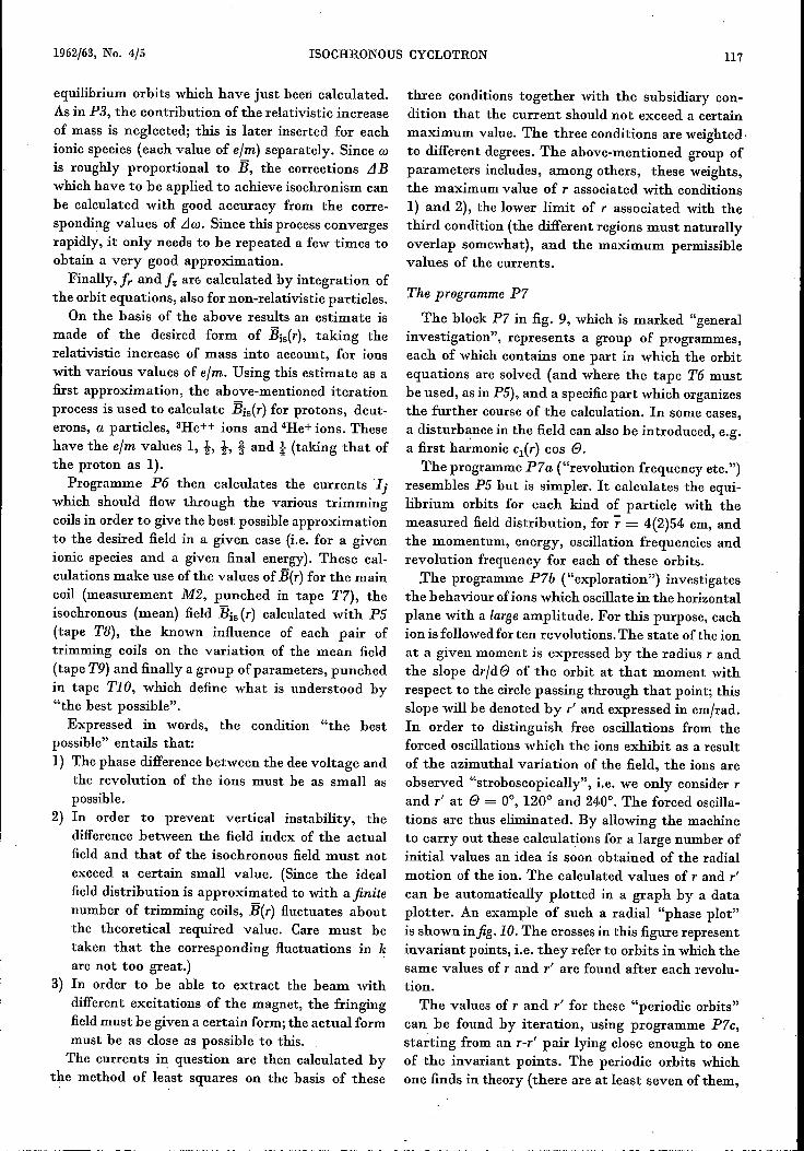
The programme P7a ("revolution frequency etc.")resembles PS but is simpler. It calculates the equi-librium orbits for each kind of particle with themeasured field distribution, for r = 4(2)54 cm, andthe momentum, energy, oscillation frequencies andrevolution frequency for each of these orbits..The programme P7b ("exploration") investigates
the behaviour of ions which oscillate in the horizontalplane with a large amplitude. For this purpose, eachion is followed for ten revolutions. The state of the ionat a given moment is expressed by the radius randthe slope dr/de of the orbit at that moment withrespect to the circle passing through that point; thisslope will be denoted by r and expressed in cm/rad.In order to distinguish free oscillations from theforced oscillations which the ions exhibit as a resultof the azimuthal variation of the field, the ions areobserved "stroboscopically", i.e. we only consider I'
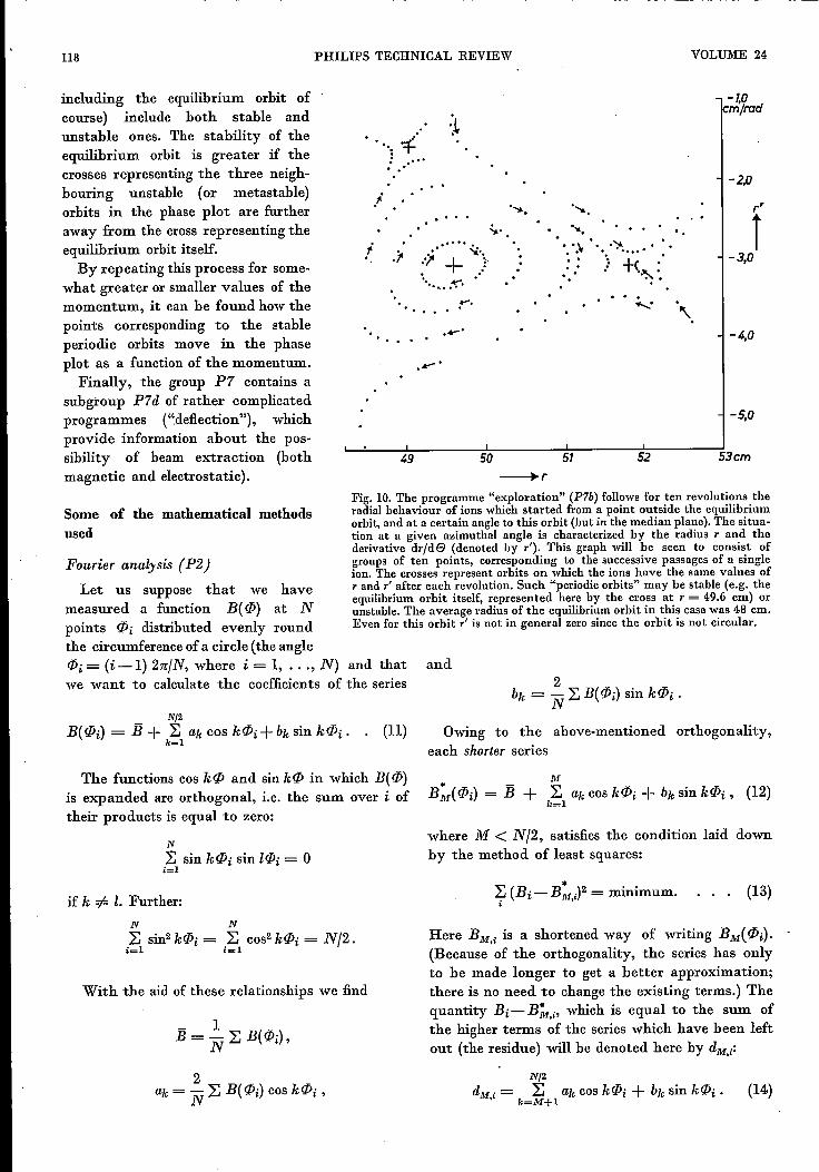
and 1" at e = 0°, 120° and 240°. The forced oscilla-tions are thus eliminated. By allowing the machineto carry out these calculations for a large number ofinitial values an idea is soon obtained of the radialmotion of the ion. The calculated values of I' and 1"
can be automatically plotted in a graph by a dataplotter. An example of such a radial "phase plot"is shown infig.lO. The crosses in this figure representinvariant points, i.e, they refer to orbits in which thesame values of rand 1" are found after each revolu-tion.
The values of rand 1" for these "periodic orbits"can be found by iteration, using programme P7c,starting from an r-r' pair lying close enough to oneof the invariant points. The periodic orbits whichone finds in theory (there are at least seven of them,
.. __ ..~-_._~~~---~--------
118
including the equilibrium orbit ofcourse) include both stable andunstable ones. The stability of theequilibrium orbit is greater if thecrosses representing the three neigh-bouring unstable (or metastable)orbits in the phase plot are furtheraway from the cross representing theequilibrium orbit itself.By repeating this process for some-
what greater or smaller values of themomentum, it can be found how thepoints corresponding to the stableperiodic orbits move in the phaseplot as a function of the momentum.Finally, the group P7 contains a
subgroup P7d of rather complicatedprogrammes ("deflection"), whichprovide information about the pos-sibility of beam extraction (bothmagnetic and electrostatic).
Some of the mathematical methodsused
Fourier analy sis (P2)
NJ2
B( if>i) = ij + ~ ak cos kif>i + bk sin kif>i .k=l
PHILlPS TECHNICAL REVIEW
": -=f'... .'l '..,.. ''».. . .
",.. '''.• • ':Ir "''l'- .' •:: •.: .+"(r .-
.' '.'" .... '.' .j . ..... "'./+).......~.
. . . . ~. ~ ....... '.._.
49 50 51 52
VOLUME 24
-1,0m/rod
-2,0
f-3,0
-4,0
-5,0
53cm
Fig. 10. The programme "exploration" (P7b) follows for ten revolutions theradial behaviour of ions which started from a point outside the equilibriumorbit, and at a certain angle to this orbit (but in the median plane). The situa-tion at a given azimuthal angle is characterized by the radius r and thederivative dr/de (denoted by r"), This graph will be seen to consist ofgroups of ten points, corresponding to the successive passages of a singleion. The crosses represent orbits on which the ions have the same values ofrand r' after each revolution. Such "periodic orbits" may be stable (e.g. theequilibrium orbit itself, represented here by the cross at r = 49.6 cm) orunstable. The average radius of the equilibrium orbit in this casewas 48 cm.Even for this orbit r' is not in general zero since the orbit is not circular.
and
(11) Owing to the above-mentioned orthogonality,each shorter series
The functions cos kif> and sin kif> in which B( if»is expanded are orthogonal, i.e, the sum over i oftheir products is equal to zero:
Let us suppose that we havemeasured a function B(if» at Npoints c}ji distributed evenly roundthe circumference of a circle (the angleif>i= (i-I) 2n/N, where i = 1, ... , N) and thatwe want to calculate the coefficients of the series
N
~ sin kc}ji sin lifJi = 0;=1
if k =1= Z.Further:N N~ sin2 kifJi = ~ cos- kifJi = N/2.ic:: I i==l
With the aid of these relationships we find
where M < N/2, satisfies the condition laid downby the method of least squares:
~ (Bi-B:ry = minimum., (13)
Here BM'i is a shortened way of writing BM(c}ji).(Because of the orthogonality, the series has onlyto be made longer to get a better approximation;there is no need to change the existing terms.) Thequantity Bi-B~,;, which is equal to the sum ofthe higher terms of the series which have been leftout (the residue) will be denoted here by dM,;:
NJ2
dM i = ~ ak COS kifJi + bk sin kifJi ., k=M+1
(14)

1962/63, No. 4/5 ISOCHRONOUS CYCLOTRON 119
The value of dM,i can be found by subtracting theright-hand side of (12) from the measured valuesof B.
During the calculation of the Fourier coefficients,the machine constantly keeps track of dM,i' The firstvalue, do,i, which applies as long as no coefficientshave yet been calculated, is equal to B - B and iscalculated as soon as B has been determined. Afterthe calculation of each successive pair of coeffi-cients, the current value of dM,i is replaced by thenext one, which is one Fourier term smaller:
dM,i = d(M_l),i - aM cos M(/Ji - bM sin M(/Ji.
After each stage of the calculation, the autocorrela-tion coefficient CF of the residue di (we shallleaveout the subscript M from now on) is calculated fromthe formula
N-l~ didi+l + dNdl
C __ i=_I_---..- _F- N
~ di2i=1
If the residue still contains periodic variations whichare larger than the random fluctuations (noise) andwhose Fourier coefficients have an index k which isless than NJ6, it can be shown that CF is positive.Ifthe residue consists mainly ofnoise, CF is negative.The machine continues the Fourier analysis until CFbecomes negative, so that no useless Fourier coeffi-cients are determined.It is not so important to finish the Fourier analysis
at the right moment in order to save time - the timesaved is not so much - but because in this way wesplit up the measured series B( (/Ji) as well as possibleinto an essential part B* and a noise part d(cf. the discussion of P2 above).
The calculation of the calibration coefficients (PI)The calibration curve contains 22 points Bi =
B(Xi), where Xi denotes the readings of the digitalvoltmeter. The method of least squares demandsthat we choose the coefficients of the approximation:
M
Bi* = ~ cnxnn=O
in such a way that Bi* satisfies an equation similarto (ll).
This calculation is based on the same principle asthat of the Fourier coefficients. We start by trans-forming xjn in a group of orthogonal functions Xn,iaccording to the procedure used for the constructionof Legendre polynomials:
n-l
Xn = xn - ~ an 1xl,1=0 '.
where the coefficients an,l are so chosen that
~ Xn,i Xl,i = 0 if n =F 1 .,Here, too, a shorter expansion of B(Xi) in powers ofXn,i is a least-squares approximation. We found byinvestigation of the residue that this becomes smallerthan 10-4 WbJm2 if M is chosen greater than or equalto 7. This is the reason for the statement that thecalibration curve must be represented by a seventh-degree polynomial.
The smoothing of the Fourier coefficients (P3)
The tables of B(r), aam(r) and bam(r) based onmeasurements of B at the equidistant points ri =0(2)64 cm are smoothed in the following manner.Let a function Yi = Y(Xi) be given at the equi-
distant points Xi. We determine a smooth function j/,with the aid of the equation
7 [<:54(Yi)]2 + K(Yi - Yi)2 = minimum, (15)
where <:54 is the fourth-order difference:
<:54(Yi) = Yi+2 - 4Yi+J-+ 6Yi - 4Yi-l + Yi-2 ,
and K is a parameter. By means of condition (15)we demand both that the function Yi should besmooth (in the sense that the fourth-order differencesare small) and that the deviations di = Yi - Yishould be small. The function is smoothed morestrongly as K is chosen smaller. Naturally, K mustnot be chosen so small that the function Yi is muti-lated and information is lost. The most suitable valueof K is found during the calculation by using suc-cessively K = 100,30,10,3, etc. in the determinationof y. After each calculation, the autocorrelationcoefficient Cs of the deviation d is calculated fromthe formula
The difference between the definition of Cs and that of theautocorrelation coefficient CF which was used in the Fourieranalysis is due to the fact that in the Fourier analysis we weredealing with a cyclic series of values, î.e. a series in which thecorrelation between the last and the firstpoint also plays a role.
For large K, Cs is negative; there is then no cor-relation between the deviations di and di+h whichis an indication that these consist entirely of noise.If K is so small that information is "planed off",there is naturally a correlation between the cor-rections applied, and Cs is positive. The calculationis therefore ended at the value of K at which Csjust becomes positive.
120 PHILIPS TECHNICAL REVIEW VOLUME 24
The processing of the measurements on the trimmingcoils (P4)
We have measurements B(rj,ej) for ri= 0(2)64cmand ej = 0(12)1080 of the main :field and of the:field obtained when one pair of coils is activated inaddition to the main coil. We obtain the contribu-tion LlB(ri,ej) of the trimming coil by taking thedifference between the two values measured at eachpoint.
It can be shown from equation (10) for the mag-netic :field that
1 9 _- L LlB(ri,ej) = LlB(ri) + Lla30(ri) .10 i=O .
In words: the mean value of the difference LlBmeasured at ten equidistant points distributed overa 1200 arc is equal to the difference between themean values of B plus the difference between theamplitudes of the 30th harmonic (cos 30 e is +1at all the points in question; the other Fourier termscancel out). Since a30 is only a few times 10-4 Wbfm2,
the term Lla30 may be neglected and we may write:
The measurements are checked by means of a rela-tionship which is also derived from equation (10) bytaking the sum D(ri) of the alternating series+Ll B(ri' eo) - LlB(rj,el), etc. This gives:
9D(ri) = ~ (-I)i LlB(ri,ej) = 10 LlaI5(ri) .
i=O
Now al5 is less than 5 X 10⁻³ Wbfm2 and Lla15 is lessthan 10-4 Wbfm2• If everything is in order, there-fore, D(ri) should be at the most about 10-3 Wbfm2•
The machine calculates the value of IDI for eachcase, and checks whether this is less than 2 X 10⁻³
Wbfm2• If this is not so, the fourth difference <54 is
calculated for each radial series, and the series inwhich the largest value of <54 occurs is corrected byradial interpolation. If IDI is still too large, the seriesof measurements is rejected.
Summarizing, we may say that the programmesdescribed above allow us to do the following things:to process a large amount of data without allowingimprobable values to slip past unnoticed; to :find.therandom fluctuations in all series of measurements,i.e, check whether the desired precision is indeedreached and maintained; to calculate the currents.in the trimming coils needed to give different ionicspecies the desired :final energy; to get an idea ofthe stability of the orbits; and :finally, to obtainenough insight into the behaviour of the ions tomake possible further development of this type ofcyclotron (e.g. with respect to the beam extraction).
Summary. An isochronous cyclotron under construction inPhilips Research Laboratories will enable different kinds ofions to be accelerated to a variable final energy (protons up toa maximum of 25 MeV). In an isochronous eyclotron the in-fluence of the relativistic increase of mass on the revolutionfrequency iscornpensated by making the induction B(r) of themagnetic field increase with the radius r. The vertical stabilityof the orbits is ensured by making B vary periodically in theazimuthal direction by means of sector-shaped hills and valleyson the pole pieces. The Philips cyclotron is also fitted with tenpairs of trimming coils, which allow the form of B(r) to bevaried to meet the demands imposed by the different ionicspecies and the different final energies. This article describeshow this complicated field is measured - for ten differentexcitations of the main coil, in connection with the desiredvariation of the final energy - and how the more than 105measured values are processed with a computer. The calcula-tions include 1) construction of the calibration curve of thefield-measuring equipment, 2) Fourier analysis of the fieldalong circular contours, 3) smoothing of the tabulated valuesof B(r) and the Fourier coefficients, 4) the calculation of theeffectof the trimming coils,5) finding the fielddistribution B(r)needed for isochrony, 6) calculating the current through thetrimming coils to give the best approximation to this fielddistribution, and finally various checks, e.g, for detecting im-probable experimental results.