Modeling the effects of aluminum and ammonium perchlorate ...
INVESTIGATION OF THE AMMONIUM PERCHLORATECOMPOSITE PROPELLANT DEFLAGRATION MECHANISM BY
MEANS OF EXPERIMENTAL ANALOG TECHNIQUES
Technical Report ME - RT 67006
by
Robert F. McAlevy, III, Suh Yong Lee,
Frank A. Lastrina, and Norman A. Samurin
September 1967
Prepared for
DEPARTMENT OF THE NAVY
OFFICE OF NAVAL RESEARCH, POWER BRANCHContract Nonr 263 (48)
~DD
L EC 2 7 1907
-L3'
CsT r.rE s INSTrIrrTUTE
3DZ:Aj T0E2T OP 196'-IAII0A EE
Rodc cCLEARINGHOUSEb _h. Or: 1,!eTO:) d , =0 t
- -C r Z-
to- Federal Scientific & Technical •r , "
Infc-mation Sprin,,,old Vi 22151,_."' .," ; " ( t
i . "C
DEPARTMENT OF THE NAVYOFFICE OF NAVAL RESEARCH
POWER BRANCHContract Nonr 263 (48)Project No. NR 092-512
I
INVESTIGATION OF THE AMMONIUM PERCHLORATECOMPOSITE PROPELLANT DEFLAGRATION MECHANISMBY MEANS OF EXPERIMENTAL ANALOG TECHNIQUES
Technical Report ME - RT 67006
by
Robert F. McAlevy, III, Suh Yong Lee,Frank A. Lastrina and Norman A. Samurin
September 1967
Stevens Institute of TechnologyDepartment of Mechanical Engineering
Hoboken, New Jersey
Reproduction, translation, publication, use and disposal inwhole or in part by or for the United States Government ispermitted.
The contents of this report have beensubmitted in partial fulfillment ofthe requirements for the degree ofMaster of Engineering (Mechanical)from Stevens Institute of Technology,June 1967.
I
ABSTRACT
Laboratory burners have been employed as a means of
studying experimentally, by analogy, the ammonium perchlor-
ate (AP) composite propellant deflagration process. A num-
ber of theoretical models of the propellant deflagration
process have been proposed. However, structural peculiar-
ities of composite propellants prevent gathering the com-
bustion data required for their evaluation. Two types of
experimental analogs have been developed and employed for
this purpose. One type, the ;porous-plug" burner, involves
the use of a porous AP bed through which fuel gases are
passed and burned at the regressing surface; similarly,
oxidant gases are burned with porous thermoplastic beds.
The other type, the "loose-granule" burner, involves mix-
tures of solid AP and thermoplastic granules that are
burned without a gaseous component. 2hus, it is possible
to evaluate the effects of fuel and oxidant initial physi-
cal. phase as they enter the flame zone, system chemistry,
and the scale of granularity (of both fuel and oxidant)
on the deflagration process.
Comparison of the loose-granule burner deflagration
characteristics with those of actual composite propellants
demonstrated that the technique is an excellent, if not
perfect, analog and that the propellant thermoplastic fuel.-
binder pocket size might play an unexpectedly powerful role
11
in the propellant deflagration process.
Comparison of "loose-granule" and "porous-plug"
burner characteristics provided edditional support to the
view that the details of energy release rate distribution
patterns have an influence on the deflagration rate of
systems containing polystyrene and polymethylmethacrylate.
Thus, such rates cannot be realistically described only in
terms of overall energy release as suggested by others.
The limits of both burners as analog techniques have
been established. For combustion pressures greater than
35 psia or so, depending on system granularity, flame pene-
tration into the interstices between granules leads to un-
stable combustion of the loose-granule burner and destroys
its analogy to normal composite propellant deflagration.
The bonding technique employed in porous-plug burner fab-
rication significantly influences its combustion character-
istics and thus mitigates the inferences that mitht be ex-
tracted from them. This suggests the work of others in
determining stoachiometrically correct mixture ratios
from burning rate-mixture ratio characteristics should be
re-examined.
The subject results reinforce the view that the burn-
er analog technique is the best means currently available
i
for testing the validity of proposed models of the ammonium
I perchiorate composite propellant deflagration mechanism.
I-I
I
TABLE OF CONTENTS
Page
TITLE PAGE
j, ABSTRACT i
TABLE OF CONTENTS iv
LIST OF FIGURES vii
LIST OF TABLES ix
SECTION I: BACKGROUND AND .INTRODUCTION 1
A. Propellant Deflagration Models 4
B. Test of the Summerfield .Equation with Propellants 8
C. Propellant Deflagration Analog Techniques 11
SECTION II: EXPERIMENTAL TECHNIQUE 14
SECTION III: RESULTS AND CONCLUSIONS 16
A. Effect of Fuel Combustion Characteristics
on Burney Deflagration 16
B. Effect of Porous-Plug Fabrication Technique
on Burner Deflagration 18
i Limitation of AP-water solution bonding 19
ii Effect of PMM-acetone solution bonding
on deflagration rate 22
C. Effect of Mixture Ratio and Combustion
Pressure on the Loose-Granule Burner
reflagration Characteristics 25
D. Comparison of the Deflagratiofi
Characteristics of the Loose-Granule
Burner and Composite Solid
Propellants by Means of the
Suminerfield Equation 27
i Comparisons via the
2/3 1P/r - P plane 28
ii Comparisons via the
P/r vs c9 plane 30
E. Visual Observations of Burner Deflagration
i The AP porous-plug burner 34
ii The loose-granule burner 36
SECTION IV: SUMMARY 39
REFERENCES 43
APPENDICES:
A. Burner Fabrication 4
i Burner tube description 47
ii Bonding of the porous-plug burners 48
iii Loose-granule burner 50
iv Igniter 51
vi
Page
B. Pressure Housings 52
C. Timing Systems 53
D. Materials and Classification 54
i Ammonium Perchlorate 54
ii Polystyrene 54
iii Polymethylmethacrylate 54
iv Classification of Granules 55
TABLES 56
FIGURES
vii
LIST OF FIGURES
FIGURE
1 Variation of Fuel-Binder Granularity With
AP Crystal Size and Mixture Ratio
2 P/r vs p2/3 Polysulfide Propellants,
Narrow Unimodal Particle Size Distributions
j bvs b0 , Polysulfide Propellants, Narrow
Unimodal Particle Size Distributions
4 P/r vs go at Various Pressures for Polysulfide
Propellant
5 Schematic of Composite Solid Propellant
Deflagration Simulator (Porous-Plug Burner
Depicted)
6 Schematic of Composite Solid Propellant
Deflagration Simulator (Porous-Plug Burner
Depicted): Modified for Optical Studies
7 Burner Deflagration Rate vs Equivalence
Ratio at Atmospheric Pressure
8 Ammonium Perchlorate Burner Deflagration
Rate vs Burner Fuel-Oxidant Mass Consumption
Ratio at Various Pressure Levels
9 Photograph of Burning AP Particles Leaving
Porous-Plug Surface
10 Ammonium Perchlorate Burner Deflagration
Rate vs Burner Fuel-Oxidant Mass Consumption
Ratio for Various Fuel Dilutions
viii
FIGURE
11 Combustion Characteristics of AP Porous-Plug
Burner fabricated by Two Different Techniques
12 Log P vs Log r at Various Mixture Ratios for
the Loose-Granule Burnerp2/3
13 P/r vs P at Various Mixture Ratios for
the Loose-Granule Burner
14 P/r vs P2/ 3 at Various Granularities for
Loose-Granule Burner
15 b vs 6" for Loose-Granule Burner
16 P/r vs go at Various Pressure Levels and
Two Ff Values for the Loose-Granule Burner
17 P/r vs f at Various Pressure Levels for
the Loose-Granule Burner} 18 Illustration of Small 'AP Granules Adhering
to a Large PS Granule
19 Timer System Circuit Schematic (Automatic
Reset)
20 Timer System Circuit Schematic (Manual Reset)
lx
LIST OF TABLES
TABLE Page
1 Deflagration Characteristics of the
Loose-Granule Burner and Composite Solid
Propellants: Pressure Varied 56
2 Deflagration Characteristics of the
Loose-Granule Burner and a Composite
Propellant: Pressure Constant 58
3 Typical Ammonium Perchlorate Analysis 59
L:
SECTION I
BACKGROUND AND INTRODUCTION
Ammonium perchlorate (AP) coarosite propellants are
widely employed in currently operational solid rocket
motors, as well as those programmed for future develop-
ment. The combustion mechanism of this type of propellant
is unknown, and so it has been impossible to produce a
rational basis for motor design, or even scaling rules
for adapting successful motors to new applications. For
example, the effect on combustion stability and efficien-
cy, ease of combustion extinction, etc. of doubling the
size and reducing to half the operating pressure of a
proven motor cannot be predicted with reasonable reliabil-
ity. Consequently, extensive development testing is re-
quired for each new motor or new application. This is
expensive, both in time and money, and there is no reason
to believe that it will always be successful. Therefore,
it appears -chat the future growth of solid propellant
rocket technology may well be paced by the speed with
which the propellant deflagrvtion process can be eluci-
dated.
Composite solid propellants usually consist of gran-
ules of ammonium perchlorate, metallic powder (such as
beryllium or aluminum), polymeric binder, plasticizer and
2
curing agent. These components are mixed together to ob-
tain a heterogeneous mixture, after which they are cast
into motor casings. During casting, care is taken to in-
sure a solid integral mass results, thereby making certain
that no inc lusions occur due to trapped gases which may
cause structural weakness. The cast mixtures are then
placed in a controlled temperature oven for, typically,
72 tc 196 hours at 150 to 190 OF for curing. At all times
extreme care must be taken with these high energy materi-
als so as to avoid detonations or explosions.
The burning surface of such propellants reflects the
heterogeneity of their compositions; they are composed of
a ccmplex of ranidomly scattered oxidizer and metallic
particles, separated only by as much binder as is- neces-
sary to fluidize the mix before curing and to produce de-
sired mechanical properties in the propellant. (Neverthe-
less, in order to produce practical propellants of stoi-
chiometrically correct mixture ratio, oxidizer crystals
in at least two different size ranges normally must be
employed.) As each surface layer burns away new particles
randomly emerge to replace those being consumed; there-
fore, the structure of the surface and the advancing
flame that consumes the vapors emerging from the surface
are both time dependent.
This formidable geometric factor has stymied the
3
development of any complete theoretical analysis of the
practical composite solid propellant deflagration process.
(Of course, any such analysis would have to account for
the normal combustion complexities of chemical reaction
kinetics and transport phenomena indigenous to all flames;
and, in addition, include a description of the surface
vaporization process - which,, at the present time is un-
known. for the propellant ingredients of interest.) In
lieu of this, various investigators have suggested dif-
ferent steps in the deflagration process as "controlling"
the overall rate in order to produce simplified models
that are susceptible to analysis. Typically, these
i heuristic approaches have resulted in algebraic rela-
tionships between deflagration rate and: combustion pres-
sure, oxidant-fuel mixture ratio, ammonium perchlorate
I crystal size, chemical nature of the fuel-binder, etc.
4, To date, this has been done explicitly only for metal-
free systems based on ammonium perchlorate crystals of a
single size.
The next step in the development of an understanding
of the deflagration process on a level that will be use-
ful for engineering purposes is to determine which of
these models best represents the actual process, if, in-
deed, any can be gainfully employed in this way. A means
for doing so, and, in fact, for generating improved models,
4
is the subject of an extensive research program under way
in the Combustion Laboratory, and this document reports
some recent results.
A. Propellant Deflagration Models
Reviews of the current status of the field have been
presented recently by Barrere and Williams (Ref.l) and by
R. Friedman, et al. (Ref.2). These reports contain a
comprehensive list of references to the pertinent work of
the past, and they are commended.
The simplistic models that have been postulated re-
sult from sweeping assumptions concerning the actual de-
flagration process, e.g., that both quasi-steady and
quasi-one-dimensional representations are valid.
All of the models that have been given serious con-
sideration are thermal in nature, e.g., the surface re-
gression rate is related directly to the rate of thermal
energy feedback from the flame above. Thus, by incorpo-
rating a heat sink at the cold boundary to account for the
phase change (and heat source to account for chemical heat
generation), and including a mechanism for material trans-
port normal to the direction of principal energy flux,
recourse can be made to the much-studied thermal theory
of premixed gaseous flame propagation. (It is appropriate
to mention here that as a result of several years of quite
productive effort, Hirschfelder (Ref.3) and his group
successfully formulated, in complete generality, the
equations governing the propagation of a premixed,gaseous,
laminar flame. However, despite a massive attack, they
were unable to solve completely the equations for any
real flame because of mathematical complexities.)
When only the conductive mode of energy transfer
back to the surface is considered, the flame thickness,
, and flame temperature, Tf f are of paramount impor-
tance in establishing the surface heat flux level. The
linearized relationship between energy absorption rate at
the surface and energy heat flux to the surface can be
expressed, in the case of conductive heating, as:
Neff (Tf - Tqff (1)
t
where: Neff is the effective thermal conductivityof the flame
T Ts is the temperature of the propellantsurface
is the mass consumption rate perunit area
qeff is the effective heat of vaporiza-tion per unit mass.
With propellant chemistry constant, Tf and "t"
are both subject to experimental ccntrol: Tf , through
its dependence on oxidant-fuel mixture ratio, and "t"
through its dependence on combustion pressure, propellant
_ _ _ _
6
scale of granularity and mixture ratio. The resulting
variation of mn can be measured quite readily. (The
quantity usually measured is the propellant surface re-
gression rate, r , which is ii divided by the propel-
lant density.) Therefore, itE appears that the validity
of Eq. 1 in describing the composite propellant deflagra-
tion processes could be easily verified experimentally;
however, this is not possible by means of experiments per-
formed with the propellants themselves because the signif-
icant parameters cannot be varied independently.
For example, although propellant granularity Js
usually characterized by oxidant granule size, ,"t"0
might depend strongly on the "granularity" of the pockets
of fuel-binder between the oxidant granules, .Tnf
order to construct a realistic model of the deflagration
mechanism it is necessary to determine the relative im-
portance of 6 and E in establishing "t" . But whenIf o
so is held constant and more fuel-binder is added to in-
crease 8f , then Tf is changed as well (since the mix-ture ratio is changed). On the other hand, when T is
f
held constant, can be varied only by varying .
Fig.l depicts schematically the variation of 6 withf
So and mixture ratio. It is clear that f' so and
T cannot be varied independently with actual composite
f
propellants. Further, for propellants incorporating
7
oxidants of a single crystal size, that is, the only type
of propellant that has been treated theoretically, only
fuel-rich compositions can be manufactured by normal cast-
ing prccedures; the range of Tf variation between this
casting limit and the fuel-rich combustion limit is quite
narrow for such propellants, and, therefore, so is the
variation in r achievable by mixture ratio variation.
-Consequently, the validity of theories of the compos-
ite propellant deflagration process based on heat con-
duction from the flame to the surface cannot be established
on the basis of the measured response of r to variation
of experimental parameters.
A number of assumed variations of "t" on combustion
pressure, P , have resulted in various predictions of r
on P (Refs.l and 2) which have had various degrees of
success in correlating propellant r (P) data. However,
successful correlation of such gross experimental data is
a necessary, but certainly not a sufficient, condition for
establishing the validity of a proposed deflagration
model. The assumed model underlying the analysis must be
tested directly, and from the preceding discussion it is
clear that such tests cannot be made with actual composite
propellants. Other means must be used.
Experiments have been made with laboratory burners
that were employed as simulators of the actual propellant
8
deflagration process. The validity of the analogs will
be established by comparing the deflagration character-
istics of the burners to those of composite propellants.
The means of comparison will be an equation produced by
Summerfield (Ref.4). Before proceeding with this compari-
,son the ability of the Summerfield Equation to represent
propellant deflagration data'must be established.
B. Test of the Summerfield Equation with Propellants
An assumed variation (Ref.4) of "t" inserted into
Eq. 1 resulted in
P = a +.bP 2/3 (2)r
where: "a" is a "reaction timewparameter depending
strongly on T
"b" is a"diffusion time"parameter, depending
strongly on propellant scale of granularity.
Within the framework of the model the reaction time
*parameter is independent of S and P, and is a function
only of propellant chemistry; and the diffusion time
parameter is a function of granularity and not of
pressure. A proposed dependence of "b" on granularity
has been suggested (Ref.5) as b = b'S where "b'" is0
assumed to be independent of both pressure and granu-
larity. Substituting this relationship into Eq. 2 yields
9
P =a + b g 2, (3)
r 0
an equation which allows the possibility of correlating
the parameters S and P with r at constant mixture0
ratio in two different planes, the P/r - P2/3 plane and the
P/r - S plane. Bastress (Ref.5) tested a number of com-0
posite solid propellants (ammonium perchlorate in a poly-
sulfide fuel-binder) of varying mixture ratio and oxidant
granule size at different pressures; these data can be
viewed within either of the aforementioned planes.
Bastrcss' data when plotted in the P/r - P2/3 plane
could be described, within a limited range of pressure
and granule size, by a series of straight lines as pre-
dicted by Eq. 2, with "b" the slope and "a" the inter-
:1! cept. Fig.2 displays some of the data (Ref.5) for which
the straight line prediction holds, e.g., for 15 /. P Z-50
psia and 78 Zo_ 230)j.. (As the granules employed in
00each propellant were not all the same size, is a num-
ber representative of the average granule diameter.) The
reaction time parameter, "a" , is not constant as assumed
by the equation, but a function of 6 . The assumed0 0
dependence of "b" is not completely consistent with the
experimental results, since the plot of b vs S for0
the data of Ref.5, depicted in Fig.3, while linear, does
not extrapolate to "b" equal zero for 6o equal zero.
0!
10
Values of "b" extracted from the data of Ref.5 are
tabulated in Table 1.
The data of Fig.2 replotted in the P/r - 0 planeo
at constan, pressure, Fig.4, can also be described by a
series of straight lines as predicted by Eq. 3. Extrapo-
lating these lines tO 6 equal zero, however, indicates0
that "a" is also a function of pressure contrary to
this theory. These values of "a", determined by varying
Co while holding P constant, and those obtained by
varying P while holding 6 constant (as described
previously) are tabulated in Tables 1 and 2.
As predicted by Eq. 3, the straight line correla-
tions of Fig.2 have slopes of b'6 and those of Fig.4
have slopes of b'P2/3. For each of these straight lines
a "b'" can be extracted. If the Summerfield scheme re-
sulted in a precise representation of propellant data,
all such values of b' should be the same. However, as
can be seen from Tables 1 and 2 these values are not the
same and, therefore, b' is a function of both pressure
and granularity.
Clearly the assumed modelwhile apparently represent-
ing some aspects of actual propellant deflagration charac-
teristics,misrepresents others. Hence, comparisons be-
tween actual propellant combustion characteristics and
those of the burner analogs based on this scheme will be
uncertain to a degree that reflects this misrepresentation.
C. Propellant Deflagration Analog Techniques
Various types of analog techniques have been employed
to model experimentally some aspect or aspects of the
composite propellant deflagration process (Refs. 1,2,6,7,
8,9,.10,13 and 14). One such propellant analog is the
pressed strand burner, (Refs. 13 and 14), composed of
granules of AP and various types of fuels compacted to
!! form a propellant strand. Two other analog techniques,
that do not involve compaction in their fabrication, have
been developed in the Combustion Laboratory; these appear to
model the essential elements of the process, including the
detailed structure of the flame zone and the burning sur-
it face, while still permitting ready experimental control of
sensitive parameters over a much broader range than is
possible with actual propellants.
One involves the use of a porous-plug in which gas-
eous fuel is passed through a burner tube laden with point
-of-contact bonded ammonium perchlorate granules (or,
alternatively, in which gaseous oxygen is passed through a
burner tube laden with point-of-contact bonded thermo-
plastic granules). The other involves the use of a bur-
ner laden with an unbonded mixture of ammonium perchlorate
I:
12
and thermoplastic granules.
Results obtained with the porous-plug burner when
compared to those of the loose-granule burner have already
produced a new insight concerning tie nature of the sur-
face boundary condition for ammonium jerchlorate combus-
tion. Ammonium perchlorate crystals were grown on thermo-
couples, and then incorporated in both types of burners;
the surface temperatures of each type of burner were
found toL have values that were quite different, although
the combustion pressures and surface regression rates were
approximately the same (Ref.6). This finding upset both
of the then-prevalent views of.the oxidant combustion
- boundary condition (i.e., thermodynamic equilibrium vs.
chemical kinetically "controlled"), and have led Powling
to propose a new view of this boundary condition for the
combustion of actual composite propellants (Ref.ll). This
is cited to illustrate the powerful impact burner analog
studies already have had on the development of composite
propellant deflagration models.
The usefulness of the porous-plug burner has been
reported upon previously (Refs. 6,7, and 8). Briefly, its
principal advantage stems from the fact that the experi-
menter selects the rate at which either the fuel or oxi-
dant is fed into the flame zone. In propellants, both
components vaporize at a rate that is fettered to the rate
13
at which heat is fed back to the surface. The porous-plug
burner permits variation of both fuel and oxidant "pyroly-
sis" rates and mixture ratio over a much broader range
than is possible with actual propellants.
The loose-granule burner permits the experimenter to
vary independently T 0 f and Tf (through its de-
pendence on mixture ratio). As described above, these are
fettered together in composite propellants due to their
peculiar structure.
This document reports on further studies of ammonium
percbhorate composite propellant deflagration by means of
these burner analog techniques. The region of applica-
bility of each has been delineated. The influence .of
ammonium perchlorate porous-plug burner fabrication tech-
nique on exhibited deflagration characteristics has been
studied. And the validity of the loose-granule burner
analog has been established by comparison of its combus-
tion characteristics with those of actual composite pro-
pellants via the Summerfield scheme.
.1______ ___________________________
-- - - -. J_
*14
SECTION II
EXPERIMENTAL TECHNIQUE
Two types of burners have been developed in this
laboratory as experimental analogs of the composite pro-
pellant deflagration process: the porous-plug burner and
the loose-granular burner. The porous-plug burner is
composed of either fuel or oxidizer granules packed into
a burner tube and point-of-conLact bonded. The burner
tubes are either of steel (in which case timing wires are
employed for surface regression rate measurement) or of
glass for visual observation of the regressing surface.
The loose-granule burner is composed of a mi:.ture of oxi-
dizer and fuel granules packed into a burner tube of
either steel or glass. The details of the fabrication of
these burners are in Appendix A.
4- For control of the burner combustion pressure two
pressure housings have been constructed within which
either type of burner can be mounted. The original hous-
ing (Ref.7) permitted regression rate data to be obtained
by means of the standard timing wire technique. A "modi-
fied" pressure housing was constructed to permit optical
study of the: combustion process, especially the nature of
the regressing surface. In order to keep the observation
windows clean, the modified housing provided for the
15
continuous removal of combustion gases. Figs. 5 and 6
are schematics of the original and the modified housings
respectively with their support equipment. Details of
the original housing are in Ref. 7 and those of the modi-
fied housing are in Appendix B.
The details of the electrical circuitry employed in
regression rate measurement by the standard timing-wire
technique are presented in detail in Appendix C. The use
of 3 timing wires with each burner permitted 2 measure-
ments of regression rate. for each run.
Tie materials used for this investigation--ammonium
perchlorate (AP), polystyrene (PS), and polymethylmetha-
crylate (PMM)--are described in Appendix D, as is the meth-
od of particle size classification.
16
SECTION III
RESULTS AND CONCLUSIONS
A. Effect of Fuel Combustion Characteristics on Burner
Deflagration
Two thermoplastics, polystyrene and polymethylmetha-
crylate, typical of those employed in composite propel-
lants were previously tested in the porous-plug burner
with gaseous 02 as the oxidant (Ref.6). During the subject
investigation these thermoplastics were studied in the
loose-granule burner with AP granules as the oxidant.
Plotted in Fig. 7 is the measured burner deflagration rate,
r , as a funtion of equivalence ratio, fo/f , for both
analog techniques (Equivalence ratio is defined here as
the measured oxidant-fuel consumption ratio normalized by
the stoichiometrically correct ratio; the latter is com-
puted by assuming that the fuel is burned to CO2 and H20,
and 02 is the only active oxidant and that ammonium per-
chlorate decomposes as follows: NH4ClOZ*1.25 02 + 1.5
H20 + HCI + 0.5 N2). Each point of Fig. 7 depicts the
arithmetic mean of at least 3 runs; all data obtained lie
within +3 percent of these arithmetic mean points. These
tests were performed at atmospheric conditions.
The porous-plug burner data depicted in Fig. 7 show
that the burning rates of the PS system are greater than
those of the PMM system. It has been hypothesized (Ref.6)
that this is probably a result of different energy dis-
tribution patterns throughout the flame zones of the two
systems. That is, since they both have about the same-l i
values of "Tf., and qeff (Ref.12), the differences in
"r" probably stem from differences in "t" j t is in-
teresting to note that similar differences between the two
systems are exhibited in practical propulsion systems; for
example, in a conventional hybrid rocket motor the PS - 02
system produced about twice the burning rate of the PMM -
0(Ref.123 . The porous-plug r vs1 charac-~2 system (Rf1Do/f
teristics for PS and PMM peak at ! = 0.5 and f = 1.0o/f o/f
respectively (Fig.7). This finding coupled with the above
hypothesis has led the authors of Ref. 6 to conclude that
PS burns in a two-stage flame,while PM14 burns in a one-
stage flame, when 0 is employed as the oxidant. Recently,2
Russian researchers (Ref.13) came to the same conclusion
based on their observations of the pressed strand burner
combustion characteristics.
The loose-granule burner data of Fig. 7 also exhibit
burning rate maxima, though, they are less pronounced.
Therefore, the aforementioned conclusion concerning PS
vis-a-vis PMM flame zone structure can be drawn for the
loose-granule burner with solid AP as the oxidant as well
v-a--------------
18
as for the porous-plug burner with caseous 02 as the oxi-
dant. Detailed interpretation of the data was prevented
by the different granularities of the materials employed,
a result of insufficient supplies at the time of the ex-
periments. Nevertheless, the results obtained indicate
that the fuel nature has an influence on the combustion
characteristics of systems employing solid AP (as well as
gaseous 02) as the oxidant over and above that of its
overall heat of combustion. This influence must be
accounted for in any complete model of the deflagration
mechanism of such systems if it is to be realistic. This
conclusion is contrary to the contentioh of Powling
(Ref. 11) that the burning rates of composite mixtures of
ammonium perchlorate with organic fuels are little affect-
ed by fuel-binder properties, other than heat of combus-
tion , at low pressures. It is consistent with results of VoWling
Russian workers (Ref. 13) based on their observation of
combustion characteristics at high pressures.
B. Effect of Porous-Plug Fabrication Technique on Burner
Deflagration
Ammonium perchlorate porous-plug burners have been
employed previously in the Combustion Laboratory (Refs. 6,
7 and 8) and in the University of Louvain in Belgium
S-
19
(Refs. 9 and 10). In both laboratories point-of-contact
bonding of the AP plugs has been accomplished but differ-
ent types of solvents were employed. In the Combustion
Laboratory the burners were bonded by using a saturated
solution of AP in water; it was assumed that use of this
bonding solution left the granule size essentially un-
altered and that the final burner contained only AP. At
the Louvain laboratory the burners were bonded using a
solution of PMM in acetone so that the AP granules were
cemented together by a thin coating of PMM.
Burners bonded by both techniques were tested during
the subject program to assess: (1) the region of applica-
bility of the AP-vater solution bonded porous-plug fabri-
cated in the Combustion Laboratory as a composite solid
propellant deflagration analog and; (2) the similarities
and differences between the two types of AP porous-plugs,
especially with regard to the influence of the PMM cement
on the deflagration characteristics.
i limitation of AP-water solution bonding
Fig. 8, a plot of r vs If/t0 at constant pressure
levels, displays data obtained with AP burners fabricated
with the AP-water solution. With r measured in the
standard way, the measured AP loading density in the tube
permitted calculation of f (Ref. 8). Each point depicts0
20
the arithmetic mean of at least 3 runs; all data lie with-
in + 3 percent of these arithmetic mean points for the 15
psia tests.
At conditions to the right of the shaded line (Fig.8)
visual observation disclosed individual AP granules leav-
ing the plug surface and burning as they were carried
downstream by the emerging methane (Fig. 9). Since sur-
face regression was influenced by this phenomenon of AP
granule dislodgement and downstream burning which does not
normally occur during combustion of composite propellants,
it is concluded that the subject type of porous-plug
burner is not a good analog of the AP composite propellant
deflagration process at operating conditions to the right
of the shaded line. Thus, it appears that this phenomenqn
imposes a pressure-dependent upper limit on the mixture
ratios for which the porous-plug burner c-n be an effect-
ive analog to solid propellant deflagration processes.
Further studies of the limit of the AP porous-plug
analog were conducted at atmospheric pressure in an effort
to separate the effects of thermal-mechanical stress on
granule dislodgement. One such study, designed to de-
termine the effect of throughput rate on mechanical
strength, was conducted by flowing gas through the porous-
plug without combustion. Visual observation revealed no
21
AP leaving the surface for gas throughput rates even
greater than that which produces the fuel-rich combustion
limit.
The other study involved combustion of the porous-
plug. First, by means of inert diluents, Tf was varied
at constant gas throughput rate, and second, gas through-
put rate was varied at constant T Depicted in Fig. 10
are data obtained during this study. Each point repre-
sents the arithmetic mean of 3 runs; all data lie within
!i + 3 percent of the arithmetic mean points. At conditions
to the right of the shaded areas visual observations dis-
closed individual AP granules leaving the plug surface
and burning as they were carried downstream (as in Fig.9),
Attempts to relate the boundary between burning with AP
j dislodgement and burning without AP dislodgement to varia-
tions in gas throughput and Tf by means of a simple con-
nection proved futile. And so it was not possible to
separate the effects of thermal and mechanical stress in
AP porous-plug burner breakup.
It was noticed that at operating conditions very
near, but still to the left side of, the shaded line in
Fig. 8 a flame appeared at the top of the burner tube.
Such flames were similar to that of Fig. 9. It is
assumed that this flame is a result of combustion of un-
burned methane with oxygen from the air within the housing.
22
This same condition, afterburning of methane at the top of
the tube, also existed for the diluted methane throughputs.
That is, this- flame would appear at values of th f/ito to the
left side of the shaded regions of each curve of Fig. 10.
Assuming mixing is complete before emergence from the
tube this flame can be considered to indicate fuel-rich
combustion in the tube. Hence, stoichiometrically correct
combustion is probably accomplished at mixture ratios
lower than that at which the analog is limited owing to
dislodgement of the granules.
ii Effect of PMM-acetone solution bonding on deflagration
rate
-I
I The influence of AP porous-plug bonding technique on
burner deflagration characteristics was investigated with
PMM-acetone solutions of varying strength. It was deter-
mined that 1.0 gm, 2.0 gm or 3.0 gm of PMM dissolved in
100 ml of acetone resulted in solutions that produced
strong point-of-contact bonding of the porous-plug. How-
ever, the l..0 gm PMM-acetone bonded porous-plug exhibited
the same phenomenon as the above mentioned AP-water solu-
tion bonded porous-plug, i.e. granule dislodgement, but at
a value of A / greater than that of the AP-water solu-f o
tion bonded plug. This phenomenon was not observed for
the 2.0 gm or 3.0 gm PMM-acetone bonded plugs.
23
These burners were tested at atmospheric pressure
with methane throughputs. The results of the 3.0 gm PMM
in 100 ml acetone are displayed and compared in Fig. 11
with those obtained with burners fabricated with the
saturated AP-water solution. Many tests were run at each
condition and the shaded areas are drawn to encompass ex-
treme data points from each type of burner. For mf/mn
greater than 0.05 the burners exhibit values of r that
are within a few per cent of each other, although the de-
pendence of r on mf/mo is somewhat different for each,
and the value of nf/mno that produces a maximum value of
r depends on the burner fabrication technique. Indeed,
for the burners fabricated by means of the PMM-acetone
solution, it was found to depend on the PMM concentration--
for 3 gm in 100 ml, the f/it for maximum r was 0.095,
while for 2 gm in 100 ml,it was 0.075.
The workers at the University of Louvain (Ref. 10)
used a 0.4 gm PMM in 100 ml acetone solution for bonding
their porous-plugs and obtained satisfactory point-of-
contact bonding. However, a 0.5 gm PMM in 100 ml acetone
solution, when investigated by the authors, did not satis-
factorily bond the porous-plug; the porous-plug granules
became dislodged by gas throughput without combustion.
Evidently the bonding solution is but one source of the
displayed differences. Each step of the overall technique,
24
may be important and should be examined in order to ascer-
tain the different results obtained.
Two porous-plug fabrication techniques were examined
at the University of Louvain (Ref. 10). In comparing the
data obtained with their samples bonded via the previous-
ly mentioned PMM-acetone solution to the data obtained by
the porous-plug fabricatioxi technique described in Ref. 7,
they found an 8 per cent increase in burning rate due to
PMM-addition, even though dislodged granules were observed
with the Ref. 7 technique. However, because of the limited
quantity of data obtainedthey did not observe that the
value of mf /mo that produces a maximum value of r de-
pends on the burner fabrication technique employed (as ob-
served in this work - see Fig. 11). Since the mixture
ratio at which the maximum burning rate occurs was em-
ployed at Louvain (Ref. 9) as a basis for determining the
stoichiometry of the AP-methane system, as well as others,
the stoichiometries they obtained must reflect an in-
fluence of the PMM cement.
Based on the above results, the following conclusions
can be drawn:
(1) The afterburner flame, appearing at the top of the
burner tube at fn/i less than 0.085, indicates that thefo0
stoichiometrically correct value for the system must be
25
less than this value. Since the workers at the University
of Louvain (Ref. 9) derived an AP decomposition scheme
based on this value being the stoichiometrically correct
value, deduced from the observation r = rmax at mf/mC =
0.085 with the PMM-bonded burners, the validity of their
conclusions are open to serious question.
(2) The location of the measured maximum burning rate
is influenced by the presence of foreign materials, in
this case PMM cement.
(3) For porous-plug burners, bonded using an AP-water
solution it was impossible to obtain r at sufficiently
fuel-rich conditions to discern accurately the value of
f/mo that produces a maximum r
(4) Therefore, determination of the AP combustion
stoichiometry will probably require measurement of the
overall chemical energy release and/or combustion product
species concentration, since neither of the current
porous-plug burner analog techniques can be employed for
this purpose when r is the only independent measured
variable.
C. Effect of Mixture Ratio and Combustion Pressure on the
ti Loose-Granule Burner Deflagration Characteristics
Shown in Fig. 12 is log r vs log P at constant
go (500- 4 2 0yA) and 8 (420- 350A.) for three mixture
26
ratios of PS and AP. This plot indicates three deflagra-
tion regimes of the loose-granule burner. Regime I is a
stable burning region where the data can be correlated
well by the familiar power law relationship:
r = BPn (4)
where; B is a constant for each system
n is a constant for each system
In Regime I, n <1, and data scatter is small (< + 4 per
cent over at least 3 runs), Regime II, a transition re-
gion, is characterized by large scatter in the data
(>+ 4 per cent over at least 3 rins) and a distinct change
in the pressure exponent from that of Regime I. Regime III
is an unstable combustion region. In this regime the
chamber pressure fluctuates during burning, and visual
observations indicate propagation of the flame front into
the interstices between granules below the regressing
surface. Thus, it is concluded that this subsurface flame
propagation limits the loose-granule burner analog in
representing the deflagration characteristics of a com-
posite solid propellant, since well-made propellants do
not include interstices within which such subsurface
flame propagation can occur.
The same general results were obtained with burners
27
fabricated with fuel granularities, o , f 500-420kf
350-297 and 297-2504 , and 6 at 500- 42 0,4, when tested0
in the same pressure range. However, burners produced by
holding constant the mixture ratio, 82% AP, and f8f
500-420,14, while changing the oxidizer granularity,
(350-297p , 297-250/k , 210-177 ? and 177-149jK ) did not
exhibit Regimes II and III when the pressure was varied
between 16 to 51 psia. On the basis of these preliminary
results it is provisionally concluded that the behavior
characteristic of Regimes II and III is produced when
Sf / So _ 1. Further study will be required before
this phenomenon can be understood.
D. Comparison of the Deflagration Characteristics of the
Loose-Granule Burner and Composite Solid Propellants
by Means of the Summerfield Equation
As described in the BACKGROUND AND INTRODUCTION the
Summerfield Equation is a relationship between pressure,
burning rate and granularity. Propellants have only one
measurable granularity, that of the oxidant; the fuel
"granularity" is inherently a function of the oxidizer
granularity. In contrast, the loose-granule burner has
two independent granularities, that of the oxidizer ( S )
and that of the fuel ( ). This additional degree of
freedom in the loose-granule system must be considered in
28
viewing loose-granule burner data in light of the Summer-
field Equation. Thus loose-granule burner data may be
viewed in an additional plane, P/r vs S , as well asf
in the P/r vs P2/ 3 and P/r vs 6 planes, which, as
previously pointed out, are of significance in interpret-
ing propellant data. The following discussion is organ-
ized around comparative views of burner and propellant
data in these planes.
i Comparisons via the P/r - P2/3 plane
The previously discussed data of Fig. 12 for which
mixture ratio is varied have been replotted in the P/r vs
p2/3 plane, Fig. 13, to allow interpretation via the
Summerfield Equation. Naturally, only data from Regime I,
within which stable burning was observed, are so plotted.
The linear correlation apparent for each of the three
mixture ratios at constant granularity, demonstrates the
applicability of the Summerfield Equation within the range
of pressure variation employed. This linear correlation
is in striking analogy with propellant data for different
mixture ratios, as reported in Ref. 4 and Ref. 5; tha1t is,
propellant data and the loose-granule burner data botn ex-
hibit straight line correlations in this plane.
Data for three typical loose-granule burner formula-
tions of the same mixture ratio but of different fuel (PS)
29
and oxidant (AP) particle size combinations are iresented
in the P/r vs p2/3 plane of Fig. 14. The typical data
shown, as well as all other data obtained in this investi-
gation, are plotted as straight lines as predicted by the
Summerfield Equation. Each point represents the arithme-
tic mean of at least 3 runs; all data lie within + 4 per
cent of the arithmetic mean points. The intercept, a
and slope, "b" , calculated on the basis of Eq. 2 for
each combination of and are tabulated in Table 1o f
(as are values of "b" and "a" for the propellants of
Ref. 4 and Ref. 5).
Contraiy to the predicti.on of the Summerfield Equa-
tion, the values of "a" obtained from the loose-granule
burner data at constant mixture ratio are not constant.
This deviation is also typical of propellant data (as
pointed out earlier) and since both deviate in this way
the analogy between loose-granule burner and composite
propellant behavior appears to be strengthened. Further
support of the analogy is provided by the fact that values
of "a" for the burners and for propellants are quite
close. (Differences in system chemistry and mixture ratio
prevent exact comparison on this point.) Also, there is
close agreement between the values of "b" from burner
data and those from propellant data presented in Table I.
(Again differences in system chemistry and mixture ratio
C'i
30
prevent exact comparison.)
To allow further comparisons between loose-granule
burners and propellants, Fig. 15 shows b vs 8 data forloose-granule burners; in one series of tests w h
loosewas held
constant while 6 was ',aried and in the other 6 was0 0
held constant and varied. While b vs plots
for propellants have been found to be linear within cer-
tain limits of parameter variation, these loose-granule
burner data are not linear within the limits of parameter
variation tested. The granularities, both and
of the loose-granule burners employed in obtaining the
data displayed in Fig. 15 are much greater than the oxi-
dant granularity of propellants that exhibit linear charac-
teristics in this plane (See Fig. 3). Hence it is reason-
able to presume that the loose-granule burner data ob-
tained in this investigation are analogous to propellant
data obtained in the "turbulent burning regime" (defined
in Ref. 5) wherein propellants do not display a linear pro-
portionality between "b" and the granularity, . Note
that both Figures 3 and 15 show "b" - 40 for o > 150,A.
ii Comparisons via the P/r vs S plane
In addition to consideration of loose-granule burner
data plotted in the P/r vs P2/3 planes and the values
of "a" and "b" determined by such plots, the measured
31
deflagration characteristics of the loose-granule burners
may be compared with those of propellants via the P/r vs
and P/r vs 6 f planes. Data taken with various
oxidant and fuel granule combinations are plotted in the
P/r vs Co plane (Fig. 16) and P/r vs 6f plane
(Fig. 17) for constant and o respectively, with PfP
as a parameter. The data for varying Go did not corre-
late to straight lines in the P/r - S plane for either
of the two fuel diameters used. However, data plotted in
the P/r vs f plane (Fig. 17) did indicate straight
line correlations within a limited pressure range (see p. 37).
One reason for this deviation from the expected re-
sult might be that the dispersion of fuel granules through-
out the more populous oxidant crystals was not uniform
from run-to-run. Assuming a uniform distribution of fuel
granules, the fuel spacing is independent of e at con-0
stant mixture ratio. And since the dependence of r on
go is weak (Fig. 16), it is concluded that if the
loose-granule burner r has a dependence on "granularity",
it must be as a result of the spacing between fuel granules
Fig. 17 indicates that f is a sensitivef
parameter in this regard.
This, at first, might appear to indicate a dissimi-
larity in the granularity dependence of burning rates in
propellants and in the loose-granule burner. For a
32
propellant of constant mixture ratio, fuel "granularity"
is a function of go only (See Fig. 1) and, therefore,
when 9O is varied Sf is also varied. In reporting pro-
pellant data the parameter usually used is G , a more
readily measured scale of granularity; however, the pos-
sibility exists that it is not the oxidant granularity but
the fuel "granularity" which determines the scale of
granularity for the combustion mechanism of composite
solid propellants. And as discussed in the BACKGROUND AND
INTRODUCTION, this question cannot be resolved by experi-
ments performed with composite solid propellants (See
Fig. 1).
Since the deflagration characteristics of the loose-
granule burner has been demonstrated to be so similar to
those of composite propellants in other regards, it seems
reasonable to assume that it will be useful in illuminat-
ing the true source of composite propellant deflagration
rate dependence on propellant granularity. But sufficient
information is not at hand to do so at this time.
From the foregoing views of loose-granule and pro-
pellant data in both the P/r vs P2/3 plane as well as
in the P/r vs f and o planes, it is significant
to compare the common aspect of both views. Slopes of the
loose-granule burner straight line correlations in the
r33
P/r- p2/3 and P/r - f planes were computed and
from these slopes, values of b' were determined via Eq. 3.
These values as well as those of the propellants of Refs.
4 and 5 are tabulated in Tables 1 and 2. It is apparent
that, just as values of b' from propellant data are dif-
ferent depending on whether they are determined from
P/r vs P2/3 or P/r vs 0 correlations, so are
values of b' from the loose-granule burner data. It is
concluded, that, while burner and propellant behavior are
analogous, Eq. 3 misrepresents both in much the same
manner and, therefore, strengthens the analog.
it should be noted, finally, that the distribution of
AP particle sizes employed in manufacture of the propel-
lantp of Ref. 4 encompassed a much broader size range than
that employed in the manufacture of the propellants of
Ref. 5. As the assumptions leading to Eq. 3 are based on
a of a single size, the data obtained from the Ref. 5
propellants should be represented by the present scheme
much better than those of Ref. 4 propellants. This, in
fact, appears to be true, i.e. the values of b' yielded
by the Ref. 4 propellants were much more scattered than
those yielded by the Ref. 5 propellants. This same con-
dition'is expected to hold with the loose-granule burner,
i.e. the narrower the particle size distributions used,
the less dispersed the apparent granularity dependence of
34
loose-granule burning rates as characterized by the para-
meter b' . In this light it is noteworthy that values of
b' determined from the loose-granule burner data of this
study fall between 0.05 and 0.10 and, thereby, display
less dispersion than the values of 0.11 to 0.37 for the
Ref. 5 propellant. This is further evidence for the analog.
In summary, the validity of the loose-granule burner
technique as an analog to the composite propellant de-
flagration mechanism has been established. It is expected
that the burner will become a primary tool for evaluation
of the various proposed models of the propellant deflagra-
tion process. As fabrication of this type of burner does
not require propellant casting, as does preparation of
composite propellant samples, the burners are less expen-
sive and safer to prepare, and, therefore, are quite suit-
able for experimentation in typical university laborator-
ies.
E. Visual Observations of the Burner Deflagration
i The AP porous-plug burner
The AP porous-plug burner with a o of 297 - 500A
has been operated at conditions from fuel-lean to fuel-
/ich and the deflagration process photographed.
For ;f/mo below 0.045 and at atmospheric pressure
pressure-
35
photographic study of the porous-plug burner combustion
'has revealed the following: the flame is visible (pale
orange) and apparently laminar within the tube; the regress-
I ing surface is slightly concave with a film of unburned
material adhering to the wall of the burner and extendingapproximately 1/4" above the surface. This region corre-
sponds to the 15 psia curve of Fig. 8 for mf/mo less
than 0.045.
For mf/mo above 0.070 an orange-blue flame ap-
pears at the top of the tube, presumably supported by
combustion of unburned fuel with oxygen in the surround-
ing environment. Therefore, it is concluded that the
combustion within the tube is fuel-rich. This region cor-
responds to values of mf/fo greater than 0.070 for the
15 psia curve of Fig. 8. The regressing surface is slightly
convex and no material adheres to the walls. The flame in
the tube, the primary flame, is pale orange and appears to
be somewhat turbulent at values of fmf/mno greater than
I 0.080. For operation with mf/mo above 0.085
individual particles can be observed leaving the surface
and subsequently burning downstream (Fig. 9). For other
AP porous-plug burners with & of smaller size, individu-o0
al particles less than 210 diameter could not be seen
leaving the surface (apparently because of their small
size); however, clusters of particles were elutriated by
36
the throughput gas and could be observed.
There is a region between the region of the concave
surface and the convex surface where a transition occurs.
In this region, 0.045< ihf/m0 < 0.070, the regressing
surface is flat with little material extending up the
walls. And the primary flame is pale orange and laminar.
ii The loose-granule burner
Ideally, fuel and oxidizer particles are distributed
randomly throughout the loose-granule burner without local
clustering of either specie. This desirable randomness
was not, however, achieved.
It was observe& prior to packing of the PS - AP mix-
ture into the burner tube that, for PS particles of less
than 200jA, clusters of PS formed in the mixture. Further,
in mixtures of large PS particles (500-4 20/k) and smaller
AP particles (177-149/A), it was observed that AP particles
adhered to the PS particles (Figure 18). Microscopic
observations of small samples of the particulate mixtures
indicated mutual attraction among particles, apparently a
consequence of the accumulation of electrostatic charge
by the PS.
It was further observed that some of the mixed AP
and PS granules adhered to the walls of the container in
3,
which they were stored before being packed into burner
tubes. The relative proportions of AP and PS which ad-
hered were not determined and so it is possible that a
change from the nominal fuel-oxidizer mixture ratio occur-
red when the mixture was transferred to the burner tube.
These observations relative to possible non-randomness
of mixing and changes in mixture ratio were not considered
in data reduction and interpretation; in the first case,
because the specie clustering was not observed for all
mixtures and is believed to be of small effect in most in-
stances, and, i.. the second case, because the proportion of
granules adhering to the container walls was small.
The regressing surface of the loose-granule burner was
observed to be flat in tests at atmospheric pressure with
no flame penetration below the surface. At combustion pres-
sures above 37 psia, however, visual and photographic ob-
servation indicated flame penetration below the surface and un-
burned solid material leaving the surface. The onset of such
interstitial flame penetration with increasing pressure was
observed to correspond with the beginning of the "transition
regime" of Fig. 12. Interstitial flame propagation is respon-
sible for the increased scatter of the highest pressure data
of Fig. 17.
Deposition of solid carbon on the burner walls during
combustion occurred in some tests. The 82% AP - 18% PS mix-
38- -
ture deposited carbon while the 90% AP - 10% PS and 86% AP -
14% PS mixtures did not. While these observations may bear
on the question of combustion stoichiometry, the connection
is not clear and was not investigated further.
4
!p39
SECTION IV
SUMMARY
The ammonium perchlorate composite propellant defla-
gration process is so complex that, for the present, tract-
able mathematical analysis of the complete problem is im-
possible. In order to produce solutions sweeping, heuris-
tic assumptions have been made which have resulted in sim-
plistic models of the actual process; these so].utions nor-
mally take the form of r(P, 0 , Tf, etc.). The workers
in the Combustion Laboratory have concluded that the valid-
ity of even these simplistic models can not be established
merely by comparing propellant data with such predictions
(Ref. 6) - - the models themselves must be tested, but
unfortunately it is impossible to perform the required
tests with actual composite propellants due to their
peculiar physical structure. Other means must be found.
In the Combustion Laboratory two types of burners have
been developed for this purpose. Results obtained with
these burners have helped clarify the nature of the piv-
otal boundary condition for ammonium perchlorate deflagra-
tion (Ref. 6).
Reported herein are the results of recent experiments
with these burners. They indicate that:
I _ _ --- ___- __ --
40
(1) The loose-granule burner technique represents an
excellent, if not perfect, experimental analog of the pro-
pellant deflagration process. In the pressure range where
the Summerfield scheme can be employed to characterize
propellant combustion characteristics (roughly, below 50
psia) comparison of propellant characteristics with suita-
ble burner characteristics revealed that: (a) both have
about the same surface regression rate, (b) values of the
parameters."ja" and "b" are remarkably similar (considering
the inherent differences, chemical and otherwise, of the
systems) and show similar trends with variation of experi-
mental parameters.
(2) In light of (1) and the demonstrated greater sen-
sitivity of burner r to S than to S. , the geometry of
thermoplastic fuel-binder pockets might have an unexpected-
ly strong influence on the propellant deflagration process --
although careful study of the influence of burner S and&S
variation on system geometry is required before a definite
conclusion can be drawn.
(3) The role of the thermoplastic fuel-binder in the
deflagration process cannot realistically be described sim-
ply in terms of its overall chemical energy release -- the
details of the energy release rate distribution pattern
through the flame zone have an influence on the deflagration
41
rate, at least insofar as PMM and PS are concerned. Al-
though this was indicated as a result of previous work
(Ref. 6), the subject results add significant support
to this view.
(4) The bonding technique used for fabricating
porous-plug burners has a strong influence on burner de-
flagration characteristics and this weakens the inferences
drawn from interpretation of them. Bonding of burners
with a saturated water - AP solution while not introduc-
ing foreign cements into the burner results in an analog
technique limit close to the mixture ratio resulting in
maximum P . This fact prevents extracting unambiguously
the value of the stoichiometrically correct mixture ratio
from porous-plug regression rate data. Further, bonding
with PMM cement results in a dependence of the mixture
ratio for maximum r on the PMM concentration of the bond-
l !ing solution (although it permits data to be gathered for
mixture ratios far beyond the limit of the AP-water-solu-
tion-bonded burners). This dependence on cement composi-
tion also prevents unambiguous interpretation of porous-
plug data in terms of the stoichiometrically correct mix-
ture ratio. Thus, it appears that this ratio cannot be
determined by measuring only the regression rates of porous-
plug burners. The work of Ref. 10 should be re-examined in
___
42
light of this result.
While limitations of porous-plug and loose-granule burn-
ers were determined during the subject program, there is,
nonetheless, no indication that the burner analog technique
is not the best available means for testing the validity
of proposed models of the deflagration of composite solid
propellants containing ammonium perchlorate.
*
7
43
REFERENCES
1) Barrere, M. and Williams, F. A., "Analytical and
experimental studies of the steady-state combustion
mechanism of solid propellants." Paper presented at
the 25th AGARD (NATO) Combustion and Propulsion Panel
Meeting, University of California (La Jolla), April
22-24, 1965.
2) Friedman, R. and Levy, J. B., "Chemical-kinetic and
physical processes in composite solid propellant
combustion," NASA Report No. 66307, Atlantic Research
Corporation, Alexandria, Virginia, January 1967.
3) Hirschfelder, J. 0. "Some remarks on the theory of
flame propagation," Ninth Symposium (International)
on Combustion, Academic Press, N. Y., 1964, pp. 553-
559.
4) Summerfield, M., Sutherland, G. F., Webb, M. J.,
Taback, H. J. and Hall, K. P., "Burning mechanism of
ammonium perchlorate propellants," ARS Progress in
Astronautics and Rocketry: Solid Propellant Research,
Vol. 1, Academic Press, N. Y., 1960, pp. 171-182.
5) Bastress, E. K., "Modification of the burning rates of
ammonium perchlorate solid propellants by particle
size control," Aeronautical Engineering Report
j ____________________
144II No. 536, Department of Aeronautical Engineering,
Princeton University, Princeton, N. J., 13 March 1961.
6) McAlevy, R. F. III and Lee, S. Y., "A porous-plug
burner technique for the study of composite propellant
deflagration on a fundamental level and its applica-
tion to hybrid rocket propulsion," AIAA Progress in
Astronautics and Aeronautics: Heterogeneous Combustion,
Vol. 15, Academic Preso, N.Y.C., N.Y., 1964, pp. 583-
608.
7) McAlevy, *R. F., Lee, S. Y., Kiczek, C. R., "Experi-
mental study of the composite solid propellant defla-
gration process on a fundamental level," Eleventh
Quarterly Progress Report, Contract Nonr 263(48),
Department of Mechanical Engineering, Stev'ens Institute
of Technology, Hoboken, N. J., July 1964.
8) McAlevy, R. F., Lee, S. Y., DeTingo, V. R., "An
experimental investigation of ammonium perchlorate
deflagration utilizing the porous-plug burner tech-
nique at elevated pressures," Technical Report ME - RT
65007, Contract Nonr 263(48), Department of Mechanical
Engineering, Stevens Institute of Technology, Hoboken,
N. J., October 1965.
45
9) Van Tiggelen, A. and Burger, J. "Oxydations et
Combustions (Chapitre XII: deflagration des
propergols solides et hybrides), "Revue de l'institut
francais du petrole et annales des combustibles
liquids, Vol. 21, No. 5, May 1966.
10) Burger, J., "Contribution to the study of deflagration
I of heterogeneous propellants," Review of the French
Petroleum Inst. and Annals of Liquid Fuels, Vol. 20,
No. 9, pp. 1-52, May 1965, Translation 1986, Bureau
of Naval Weapons Contract NOw 62-0604-C, Applied
Physics Laboratory, Johns Hopkins University, Silver
Spring, Maryland, Feb. 1967.
11) Powling, J. "Experiments relating to the combustion
of ammonium perchlorate - based propellants," Eleventh
Symposium (Cnternational) on Combustion, The Combustion
Institute, Pittsburgh, Pa., 1967, pp. 447-456.
12) Houser, T. J. and Peck, M. V., "Research in hybrid
combustion," AIAA Progress in Astronautics and
Aeronautics: Heterogeneous Combustion, Vol. 15,
Academic Press, N. Y. C., N. Y., 1964, pp. 559-581.
46
13) Tsyganov, S. A., Bakhman, N. N., and Yevdokimov,
V. V., "Combustion of condensed mixtures with poly-
dispersed components," Translation by NASA, Science
and Technical Service, Report No. N 66-33081.
14) Adams, G. K., Newman, B. K., and Robins, A. B.,
"The combustion of propellants based on ammonium
perchlorate," Eighth Symposium (International) on
£, Combustion, Williams and Wilkins Co., Baltimore,
Md. 1962, pp. 693-705.
ii
47
APPENDIX A
Burner Fabrication
i Burner tube descriDtion
Two types of burner tubes were employed. To permit
visual and photog;:aphic observation of the combustion
process, heat resistant glass ("Pyrex") tubes
(0.51" O.D. X 0.47" wall) in lengths of 6" or 8"
were used. For regression rate measurement stainless
steel tubes (0.50" O.D. X 0.049" wall) in lengths of
6" or 8" were used. At each of 3 equidistant stations
along the tube length, 2 radial holes were located and
drilled, using a Number 60 drill, through opposite
sides of the steel tube. A timing wire, which con-
sisted of a 6" length of fuse wire (Bussman 2 amp),
was then threaded through the tube at each station.
At the six points where the wires pierced the tube
wall the wires were coated with ceramic cement
C'Sauereisen") to insure rigid placement and to in-
sulate the wires electrically from the tube. In
both types of tube paper wadding was used at the
lower end of the tubes to support the loose granules
within the tubes.'I
48
ii Bonding of the porous-plug burners
Several techniques for bonding the loose AP granules
to form a strong porous-plug have been employed in
this laboratory. Two previous methods have been re-
ported (Ref. 7 and 8) but subsequent investigation
revealed that the reproducibility of regression rate
data from burners made using these techniques was
unsatisfactory.
The first bonding method (Ref. 7) involved subjecting
the tubes, fully loaded with AP granules, to a
quiescent atmosphere of moist air for approximately
six hours and subsequent drying in an oven maintained
at 100 0F. However, by drilling through or burning
away the end of the plug it was found that the bond-
ing extended only to a depth of approximately 1" in
some cases, so that the underlying AP remained in
its original unbonded condition. This indicated
that the moist quiescent atmosphere was incapable of
producing a uniformll bonded condition throughout
the length of a 6" or 8" plug, a prerequisite for
reproducibility. This technique was abandoned.
The second technique (Ref. 8) depended upon the fact
that water is a solvent for AP whereas ether is not.
A 25% (by volume) solution of water in ether was
________________________
49
permitted to gravitate through a tube containing
loose AP granules. It was hoped that this water
content would be sufficient to form a point of
contact bond between granules but insufficient to
dissolve the AP particles appreciably. Several
deficiencies were found in this technique. Examina-
tion of a 25% "solution" of water in ether revealed
that almost none of the water remained in solution
with the ether but had settled out. Thus, granules
subjected to this mixture would be immersed either
in water, causing partial dissolution of AP and hence
greatly reducing the size of the particles in the
tube, or in ether, producing no bond at all.
These drawbacks were eliminated with the present
bonding technique that finally evolved. A tube
filled with AP granules is compacted by tapping
75 - 100 times and the resulting empty space at the
top filled with more AP. The bonding solution is
prepared by dissolving.AP in water at 150OF until
a saturated solution is obtained, and then cooling to
room temperature before use. A vacuum is drawn at
the bottom of the tube as the bonding solution is
poured through the packed granules - 1.5cc of solu-
tion per inch of packed plug.
NL
50
After the solution has wet the entire length,
suction is continued for 3 minutes to initiate dry-
ing. The tube is placed in a constant temperature
oven (at 1500F.)for 6 hours, cooled to room tempera-
ture, and dry air is then passed through for one
additional hour.
The porous-plugs bonded by the above system did not
exhibit those properties which invalidated theprevious techniques. The bonding solution insures
a minimum reduction of the selected AP granule
size. Examination of the plug via the methods used
on the previous systems proved that the porous-plug
was bonded throughout its entire length.
'I
The porous fuel plug is produced in a similar manner
to that of the oxidant plug. The major differences
are that methyl ethyl ketone is \ sed as the bonding
solution and that no heat is used in drying the tubes.
iii Loose-granule burner
Fuel (PS) and oxidant (AP) were blended mechanically
(Appendix C) or manually in varying weight ratios in
300 gram quantities. There was no noticeable differ-
ence in the physical appearance of the mixture(or
data produced)with either blending technique. Tubes
1 51
were then filled with the mixture, tapped 75 - 100
times, and the resultant void refilled. Tapping is
an important step since uncompacted tubes have
exhibited up to 15% faster burning rates than com-
pacted ones.
iv Igniter
The igniter charge consisted of a mixture of 14%
PS - 86% AP by weight. A 1 " length of #30 gauge
nichrome wire was used as the heat source. A length
of paper (drafting) tape was wrapped around the top
of each burner tube forming a " extension of the
tube wall. The tape was pierced on opposite sides
and the wire threaded through, leaving " projecting
on the outside of the tape for the electrical connec-
tions. The charge was then poured into this exten-
sion, covering the wire. With porous-plug burners,
three drops of acetone were added to the top surface
of the igniter charge in order to bond the granules
and thereby prevent elutriation by the throughput
gas. With the loose-granule burners no bonding was
required.
I'
52
APPENDIX B
Pressure Housings
During operation of the original pressure housing
(Ref. 7), the combustion products accumulate in the hous-
ing and prevent visual observation of the regressing sur-
face through the windows. This condition necess.itated
the construction of a new pressure housing from which
these combustion gases could be continuously exhausted.
The new housing was a Penberthy high pressure boiler
sight glass (Penberthy Co., Prophetstown, Ill., Model
No. WT-13). The installation of i critical flow orifice
in the exhaust line permitted the establishment of the
desired equilibrium chamber pressure during operation.
The bottom of the chamber was fitted with a 2 inch pipe
union. The female end was connected to the housing and
the male end closed by a steel cap. The cap was con-
structed to accept a burner tube holder, pressure tap,
electrical tap and nitrogen gas supply line. The pressure
gages, ignltion source and methane flow system were used
interchangeably with both the original and the modified
housings. Figs. 5 and 6 are schematic of the original
and the modified housings, respectively, with their support
equipment.
I
53
APPENDIX C
Timing Systems
During the course of the subject program, two timing
systems were used.
Initially, a system was employed incorporating single
pole, double throw relays (Potter and Brumfield Co., Model
PW5DS - 6vdc. ) with automatic reset. Fig. 19 is a wiring
diagram of this system. This circuit, however, proved
inadequate since a short circuit could be caused by a
I melting timing wire making contact with either the tube
I or another wire.
I The possibility of short circuits was eliminated by
an improved system which used stacked, double pole, double
If throw relays (Kurman Electric Co., Model KXlH2E, 6 vdc.)
providing for manual resetting. Fig. 20 is a wiring
diagram of this system.
Two pairs of timing clocks (Standard Electric Time
Co., Model S-13H-10 and Model S-l) were used interchange-
ably in the two timing systems.
54
APPENDIX D
Materials and Classification
i Ammonium Perchlorate
The ammonium perchlorate used in this investigation
was purchased from the American Potash and Chemical
Company, Los Angeles, California, and did not con-
tain an anticaking agent. Particle size range was
specified and various weights of material were
ordered at different times. Table 3 displays a
sample analysis of three separate orders.
ii Polystyrene
The polystyrene used in this study was purchased from
the Sinclair-Koppers Company, Plastics Division,
Monaca, Pennsylvania, under the trade name of Dylene
8X. The material was ordered in two size ranges,
30 fines, (500 to 200p), and 60 fines, (250 to 50 4).
Rounded beads were specified.
iii Polythyimethacrylate
The polymethylmethacrylate used in this investigation
was purchased from Rohm and Haas Co., Philadelphia,
Pa., under the trade name VM - 100 Plexiglas. The
material was ordered as molding powder (colorless
LrL55
pellets) approximately 1/8" in diameter. These
pellets were ground by hand with mortar and pestle
to obtain small sizes.
iv Classification of Granules
A series of screens (Tyler) were employed to separate
the "as received" granular materials into fractions
having a specific range of granule diameter. A
Ro-Tap sieve shaker (Tyler Company, Cleveland, Ohio)
was used to vibrate the screens and thus move the
granules through them. This granule size classifica-
tion method was successful for AP granule diameters
greater than 7 . Below 74P the screen holes tend
to clog making further classification extremely
] dift.cult. Unfortunately, with the polystyrene
granules less than 210/h in size, accumulation of
electrostatic charge by the granules caused them to
adhere to the screens. Hence, granules less than
210,M could not accurately be classified by this
method.
r 56)
rqIN
vz M. HJLAq M - A~D~ M0r M i N N N C4M n 0 IV~ -1 M (1
1- E-44 O 00 0 H H N N r e
P ~ ~ ~ N~4 aia ale 00 AHr4 - 1 N r4 O- HV- (r I N
H 4 H
E ooo CA 0 0 0 oo00000F4 0- Or-IN 04 A a% inr 0 C)ai inN a% ci q 3 %o
H 0 0 An~ NIV N(74f H in(71 CN 10 HHH14I~U) 001 11 111 1III:: I II I I I I I
oo0oor -o0r a 0r-o 0t 00 00 0--4 NL 0 ~ r- c,4 ~ - I
U E-4 R ~N i m N N 14 m Nui ,4 , - -N H
9 U)S0
00 o or-. 0 C)U LN O AO'0 LA 0
4 '4-1 WA~ %D o N inOo 00 00- m %D.
0 E- N0 M) 9 A
04~ P4 U):I IH4 H N
_ _0 _ _ _ _ _ _ _ _ 0._ _
.57
C: 0) M Ln rn) ko
0Q 0 H 0
C,. 0)
*1E-1
~A .I ~ L
0 k0 0 %DoN H- C% H-
0 0-u 4OD
444
E40
r114
E4QF- H00 oE-
____________________________ _______ ____________n
58
+ + +
0- ' C r- H ; C
+ + +*i4C)0 0 0 0 0r- LA 0 0 %0 m.Q N , N mv m~ M~ m 10
P4' 4.) m o ul 0 o
H4 fu H N-• '
pi c 0 0 .IA 0
- 0
I =
O ,z
o0 E-1 0 N
U) -~ H- ch 000 N N L
- 0 I 1 1E-4 C) CN 0:(3 H N
4N N >
0 N-N N 0En z
H
E-4 _ _ __
U) o V ra0o +C4rA) C
E- 0- (d r0zdi
~ H 00
0-
- E-4_ _ 8
4 f
59
TABLE 3: TYPICAL AMMONIUM PERCHLORATE ANALYSIS
Supplier: American Potash and Chemical Corporation,Los Angeles, California
Analysis of Material
Batch #1 Batch #2 Batch #3
NH4C!o4' % 99.7 99.7 99.7
NH4 Cl, % 0.03 0.013 0.018"
NaC 3 % 0.006 0.008 0.006
Moisture total, % 0.02 0.019 0.082
Sulfated Ash, % 0.09 0.06 0.08
(NH) 2 So4' % Trace Trace Trace
Insoluble acid, % 0.003 0.003 0.006
' Metal Oxides, % 0.009 0.004 0.002(Non alkali)
Na Bromate, % 0.001 0.0008 0.001
pH Value 5.4 .5.0 4.7
Particle Size Distributions
) 420p , % 45.8
> 35 0), % 90.7
>297p , % 2.8 6.6 99.1
\210) , % 42.7
> 149tA , % 79.6 73.9
>105p , % 90.8 91.0
) 74 , % 98.8 99.6
> 4 4,", % 100.0
-i
NEAR STOICHIOMETRICALLY CORRECT MIXTUREFUEL-BINDER
FUEL-RICH MIXTURE
FUEL-BINDER
MIXTURE HELD CONSTANT
SMALL LARGECRYSTALS CRYSTALS
AP AP
FIG. I VARIATION OF FUEL-BINDER GRANU-LARITY WITH AP CRYSTAL SIZE ANDMIXTURE RATIO.
P/r (PSCA/IN./ SEC)
0 0 00 0"0 0 0 0 0
000
> -u C
0 w~
m r3-n
Nm
0\ M
.0 '0
c: >1zN
0'
'A ',U)w
• I
.cr.
.. -0 0o N1 I1
0 -<W ZZ
00
(0
1J1
.U
CLOW
ow
00 CL0
0
'.j
(00
0 0 0 0 0'1" 1 . oa 0-
__
( O S/"NltsV~d)0
g0
tocl
65%AP50 PSIA
H w
a.40
200DATA OF bASTRESS
REF. 5
0o 100' 200. .300
FIG.4 P/r vs Bo AT VARIOUS PRESSURES FORPOLYSULFIDE PROV)ELLANT...
LI)d
z U)
OOLL o L
oz~H z oOC1 0 0
Dn w -ac
w (
WW
L0 -
zw CA-
0 a:- Z
W, H )
CA
0(0W0
0co~~ CA co
>'0 0 )OGM )- :(fl-U-z a
00 -
000a1 x1
P10 <C0-u C 0
_ 0
zr
0rr
0o 0*Jc N
0000
oo1 1 0001,-0 lG
oou* <CD w z
Dl ~ZF-
< 0<
0 z0
w wQ
I I g - W 60
I-
0 0 0 0a0
o d(03S/NI) J '3LV8I NOIIMENU3G 83N~ifl
0.14 150 PSIA
0.1
w w/
1-- 0.10-E '/ BURNING CRYSTALS
1 00 PSIA LEAVE SURFACEz0
0.08 -(p
(..9 50 PSIA ,
-J
0.06-I•
LaJJz~0.04.
5PSIA
0.02- AP CRYSTAL SIZE: 297-500pFUEL: METHANE
NOTE: 150, 100, AND 50 PSIA DATAARE FROM REF.8
0I I
0 0.02 0.04 0.06 0.08 0.10BURNER FUEL-OXIDANT MASS CONSUMPTION RATIO,r f/mo
FIG. 8 AMMONIUM PERCHLORATE BURNER DEFLAGRATIONRATE VS. BURNER FUEL-OXIDANT MASSCONSUMPTION RATIO AT VARIOUS PRESSURELEVELS.

AFTER4 IBURNING
FLAMEI 0_ BURNER
TUBE
..DISLODGEDi PARTICLES
REGRESSING*I Nt SURFACE
POROUSt ii!? .. .... .
rhf/rho: 0.09 PRESSURE: 15psioAP CRYSTAL SIZE: 500-297L
FIG. 9 PHOTOGRAPH OF BURNiNG APPARTICLES LEAVING POROUS-PLUG SURFACE.
__/
0.04 AP CRYSTAL SIZE: 500-297 PRESSURE: ATMOSPHERIC
(.)w-. 0.03/
I ..
l, zw
0! 0.02-_H
"J BURNING CRYSTALSI L EAVE SURFACE
It 0GAS COMPOSITION: VOLUME PERCENTw 0.01 0-100% CH 4 A-20% N2*z4
A -20% He* -40%N 2 *
o a -40% H - 6.5 % N2*
I <-BALANCE CH4
0 002 0.04 0.06 0.08 0.1I0
BURNER FUEL-OXIDANT MASS CONSUMPTION RATIO,rnf /m0\
FIG.IO AMMONIUM PERCHLORATE BURNER DEFLAGRATIONRATE vs BURNER FUEL-OXIDANT MASSCONSUMPTION RATIO FOR VARIOUS FUEL DILUTIONS
I
0 WASHED WITH SATURATEDLdW0 SOLUTION OF AP IN WATER
" 0.03zL
L1
It WASHED WITH SOLUTIONOF 3GM PMM IN 100 ML ACETONE
Zoi 2H 1- 0.02.
_JLLw
w AP CRYSTAL SIZE: 5 00 -297Mz FUEL: METHANE
0.01 - PRESSURE :ATMOSPHERICED
0-NOTE : EACH SHADED AREA. COVERS ALL DATA
OBTAINED
0 I I I I
0 0.03 0.04 0.06 0.08 0.10BURNER FUEL-OXIDANT MASS CONSUMPTION RATIO, rnf/rn o
FIG. II COMBUSTION CHARACTERISTICS OF AP POROUS-PLUG BURNERS FABRICATED BY TWO DIFFERENTTECHNIQUES.
0.40- 90% AP
u x 86% AP REGIME Mw(j) 0 82% AP UNSTABLE
0.20wI-
a:
z0 REGIME 11"0.10• (TRANSITION)
C 0.08 ,-,,, 0.06-
z 0.04 - REGIME I0.04 0 (STABLE)
m0.03- bf: 4 2 0-3 501L80: 500-420p
15 20 30 40 5060 80PRESSURE, P (PSIA)
FIG. 12 LOG P vs LOG r AT VARIOUSMIXTURE RATIOS FOR THELOOSE-GRANULE BURNER.
8o :500-420,L
af:420-3501L
600-
w
1.400
I--
00"///
0 82% AP0 86% AP
A 90% AP
0 2 4 6 8 10 12p2/3 (PSIA )2 /3
FIG. 13 P/r vs P=t3 AT VARIOUS MIXTURE RATIOSFOR LOOSE-GRANULE BURNER.
I
82%AP
600-
00
w
< ' 400 -
200
o-a :3 5 0- 2 9 7pi bo:500-420&
- 8f :350-297pt 8o :350-297,u
A-8f :500-420; 80:350-297p&
00 2 4 6 8 10 12
p213 (PSIA) 13
FIG. 14 P/r vs P213 AT VAFCOUS GRANULARITIESFOR LOOSE-GRANULE BURNER.
50 82%AP
40
>30-2i 0
0 00
U)
0. 20-
o- 8o:500- 4 2 0= bf: VARIED
10- A-8f:500-420u, 8o:VARIED
O0I I -
0 100 200 300 400 500
FIG. 15 b vs 8 FOR LOOSE-GRANULE BURNER.
'71
L-i
P/r (PSIA/lN./SEC)
ON 0
0 0
to co4-
0C0
00
000 0 0 o
tm--4
00
0a 0
> a 0-
z Cl 0 C) C l
w cnC:'
82%AP
600 8:50 0 -42 0px
X
500 x
400-
ii 300
,,,.
200xX
100 r3- 16 PSIA 8 DATA POINTS (MEAN)0 - 23PSIA. P "I gg
X -37PSIA SINGLE DATUM POINT0I , . I
0 100 200 300 4008 f (pL)
FIG. 17 P/r vs 8f AT VARIOUS PRESSURELEVELS FOR THE LOOSE-GRANULEBURNER.
,
82% AP 80 177 -149 IL
, bf :500-420FL
FIG. 18 ILLUSTRATION OF SMALL AP GRANULES
ADHERING TO A LARGE PS GRANULE.
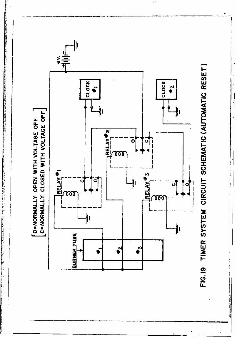
U.UC) L
wL C)
JI
II
0 oiIIQ
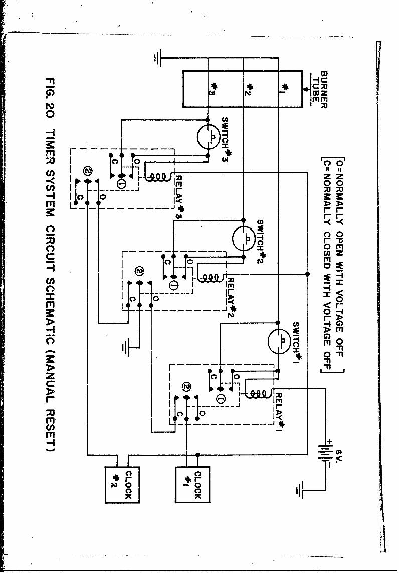
-q1
rn F
I~ z
o 00
CI x~~ m.4 I _
Ir T
C: 0
II mOCA1
rri- r
0 I
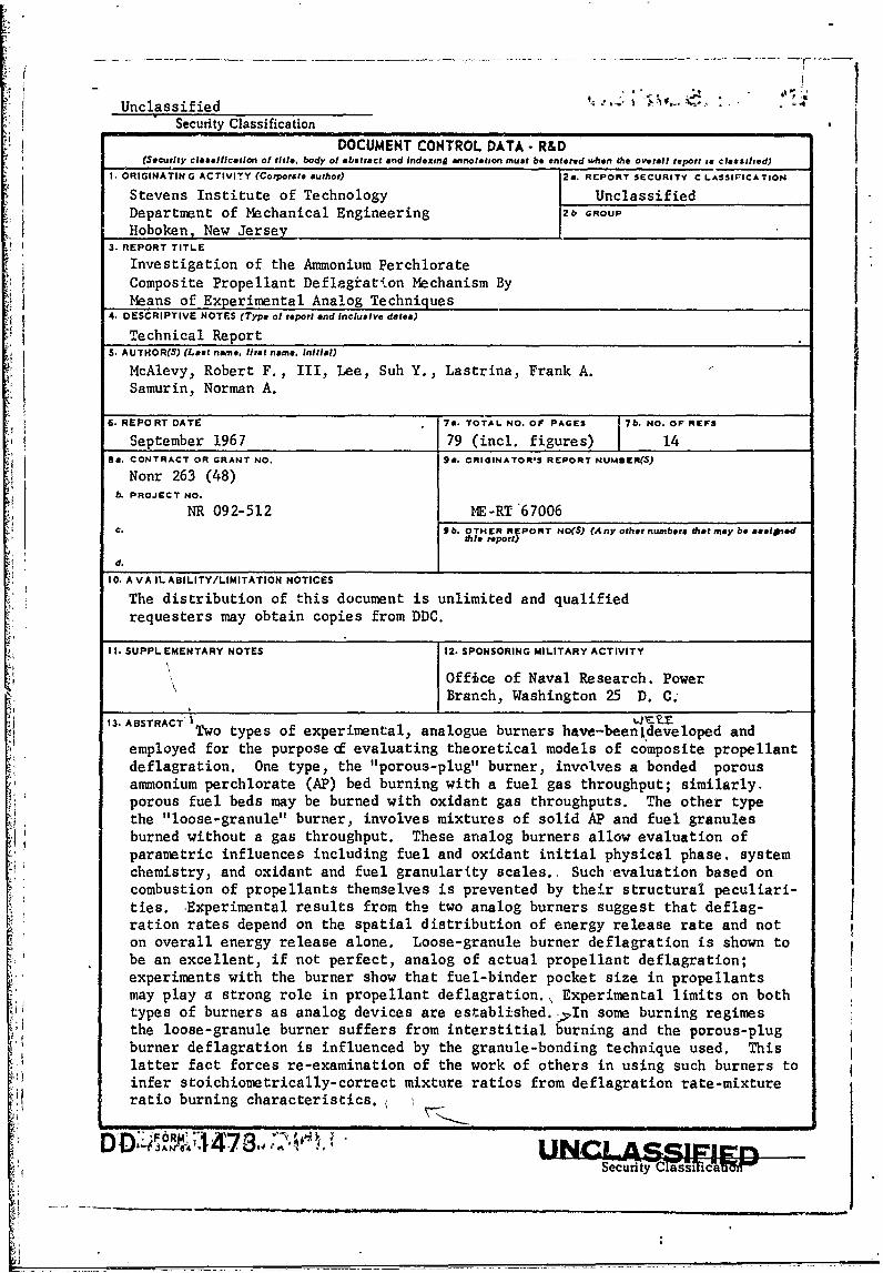
Unclassified -'"' ""'Security Classification
DOCUMENT CONTROL DATA -R&D(Security classification of title, body of abstract and indexing annotation must be entered when the overall report ia classified)
I. ORIGINATING ACTIVITY (Corporate author) 28. RCPORT SECURITY CLASSIPICATION
Stevens Institute of Technology UnclassifiedDepartment of Mechanical Engineering 2b GROUP
Hoboken, New Jersey3. REPORT TITLE
Investigation of the Ammonium PerchlorateComposite Propellant Deflagration Mechanism ByMeans of Experimental Analog Techniques
4. DESCRIPTIVE NOTES (Type of report and Inclusive dates)
Technical ReportS. AUTHOR(S) (Last name. first name, initial)
McAlevy, Robert F., III, Lee, Suh Y., Lastrina, Frank A.Samurin, Norman A.
6. REPORT DATE 7a. TOTAL NO. OF PAGES 7b. NO. OF REFS
September 1967 79 (incl. figures) 148a. CONTRACT OR GRANT NO. 9a. ORIGINATOR'S REPORT NUMBER(S)
Nonr 263 (48)b. PROJECT NO.
NR 092-512 NE-RT"67006C. Sb. OTHER RIPORT NO(S) (Any other numbers iot may be asslned
tle report)
d.
10. A VA IL ABILITY/LIMITATION NOTICES
The distribution of this document is unlimited and qualifiedrequesters may obtain copies from DDC.
Il. SUPPLEMENTARY NOTES 12. SPONSORING MILITARY ACTIVITY
Office of Naval Research. PowerBranch, Washington 25 D. C;
13. ABSTRACT I
Two types of experimental, analogue burners have-been'developed and
employed for the purpose o evaluating theoretical models of composite propellantdeflagration. One type, the "porous-plug" burner, involves a bonded porousammonium perchlorate (AP) bed burning with a fuel gas throughput; similarly.porous fuel beds may be burned with oxidant gas throughputs. The other typethe "loose-granule" burner, involves mixtures of solid AP and fuel granulesburned without a gas throughput. These analog burners allow evaluation ofparametric influences including fuel and oxidant initial physical phase, systemchemistry, and oxidant and fuel granularity scales. Such evaluation based oncombustion of propellants themselves is prevented by their structural peculiari-ties. -Experimental results from the two analog burners suggest that deflag-ration rates depend on the spatial distribution of energy release rate and not
on overall energy release alone. Loose-granule burner deflagration is shown tobe an excellent, if not perfect, analog of actual propellant deflagration;experiments with the burner show that fuel-binder pocket size in propellantsmay play a strong role in propellant deflagration.\ Experimental limits on bothtypes of burners as analog devices are established. In some burning regimesthe loose-granule burner suffers from interstitial burning and the porous-plugburner deflagration is influenced by the granule-bonding technique used. Thislatter fact forces re-examination of the work of others in using such burners toinfer stoichiometrically-correct mixture ratios from deflagration rate-mixtureratio burning characteristics.(
i7- _147 -3 ,_
U.1NLASSIFIEDSecurity Classification
14. LINK A LINK 8 LINK CKEY__ ORDS ROLE WT ROLE WT ROLE WT
Ammonium PerchlorateAnalog TechniquesCombustion MechanismComposite PropellantsParticle Size EffectsPolystyreveSolid Propellant Combustion
I INSTRUCTIONS
h. ORIGINATING ACTIVITY: Enter the name and address imposed by security classification, using standard statementsof the contractor, subcontractor, grantee, Department of De- such as:
eother (corporate author) issuing (1) "Qualified requesters may obtain copies of this
the rport.report from DDC."2a. REPORT SECURITY CLASSIFICATION: Enter the over- (2) "Foreign announcement and dissemination of thisall security clasfiication of the report. Indicate whether report anno t anh ie"Restricted Data" is included. Marking is to be In accord- report by DDC is not authorized."ance with appropriate security regulations. (3) "U. S. Government agencies may obtain copies of
this report directly from DDC. Other qualified DDC2b RU:At.omatic downgrading is specified in DoD Di-uessalreus hog
rective 5200. 0 and Armed Forces Industrial Manual. Enter users shall request through
the group number. Also, when applicable, show that optionalmarkings have been used for Group 3 and Group 4 as author- (4) "U. S. military agencies may obtain copies of thisized. report directly from DDC. Other qualified users
3. REPORT TITLE: Enter the complete report title in all shall request throughcapital letters. Titles in all cases should be unclassified.If a meaningful title cannot be selected without classifica-tion, show title classification in all capitals in parenthesis (5) "All distribution of this report is controlled. Qual.immediately following the title. ified DDC users shall request through
4. DESCRIPTIVE NOTES: If appropriate, enter the type of ._report, e.g., interim, progress, summary, annual, or final. If the report has been furnished to the Office of TechnicalGive the inclusive dates when a specific reporting period is Services, Department of Commerce, for sale to the public, indi-covered. cate this fact and enter the price, if known.
5. AUTHOR(S): Enter the name(s) of author(s) as shown on IL SUPPLEMENTARY NOTES: Use for additlonel explana-or in the report. Enter last name, first name, middle initial, tory notes.If military, show rank and branch of service. The name ofthe principal author is an absolute minimum reqturement. 12, SPONSORING MILITARY ACTIVITY: Enter the name of
the departmental project office or laboratory sponsoring (pay-6. REPORT DATE: Enter the date of the report as day, ing for) the research and development. Include address.month, year, or month, year. If more than one date appearson the report, use date of publication. 13. ABSTRACT: Enter an abstract giving a brief and factual
summary of the document indicative of the report, even though7a. fIOTAL NUMBER OF PAGES: The total page count it may also appear elsewhere in the body of the technical re-should follow normal pagination procedures, i.e., enter the port. If additional space is required, a continuation sheet shallnumber of pages containing information. be attached.
7b. NUMBER OF REFERENCES: Entes the total number of It is highly desirable that the abstract of classified reportsreferences cited in the report. be unclassified. Each paragre,h of the abstract shall end with8a. CONTRACT OR GRANT NUMBER. If appropriate, enter an indication of the military security classification of the in-the applicable number of the contract or grant under which formation in the paragraph, represented as fTS). (S), (C), or (U).the report was written. There is no limitation on the length of the abstract. How-
&b, 8c, & 8d. PROJECT NUMBER: Enter the appropriate ever, the suggested length is from 150 to 225 words.military department identification, such as project number,subproject number, system numbers, task number, etc. 14 KEY WORDS: Key words are technically meaningful termssubpojet nmbe, sytemnumers tas nuber et. Ior short phrases that characterize a report and may be used as
9a. ORIGINATOR'S REPORT NUMBER(S): Enter the offl- index entries for cataloging the report. Key words must becial report number by which the document will be identified selected so that no security classification is required. Identi-and controlled by the originating activity. This number must fers, such as equipment model designation, trade name, militarybe unique to this report. project code name, geographic location, may be used as key9b. OTHER REPORT NUMBER(S): If the report has been words but will be followed by an indication of technical con-assigned any other report numbers (either by the originator text The assignment of links, roles, and weights is optional.or by the sponsor), also enter this number(s).
10. AVAILABILITY/LIMITATION NOTICES: Enter any lim-itations on further dissemination of the report, other than those
iJ
UNc LAssiFIEDSecurity Classification