INVESTIGATION OF CRACK GROWTH BY LOADING FATIGUE DUE …
10
INVESTIGATION OF CRACK GROWTH BY LOADING FATIGUE DUE TO FLUID AND STRUCTURAL COUPLING VIBRATIONS IN THE JOINT OF THERMOWELL WELDING IN GAS PIPELINE Masoud Rahmani 1 *, Amin Moslemi Petrudi 2 1, 2 Department of Mechanical Engineering, Tehran University, Iran * Corresponding author. E-mail: [email protected] Abstract One of the types of damage in structures is cracking, which leads to many failures when it initials to grow. The aim of this project is to investigate the growth of fatigue cracking at the joint of thermowell welding to the main pipeline. Thermowell is used to measure fluid flow temperature. Methane gas flows in the main pipeline, which creates vibration in the pipe. In this study, the problem is divided into two parts. Initially, the problem of fluid coupling and structure is solved and the range of displacement is obtained in the welding section. In the second stage, by creating the initial crack with a length of 1 mm, this range is periodically attributed to the welding section. And crack growth diagrams are obtained with respect to time and the effect of frequency on the stress contour. The results show that the growth rate increases with increasing frequency. Therefore, by changing the geometry of the thermowell and reducing its frequency, it reduced the rate of growth of damage in the weld. Decreasing the thickness of the shell and reducing the diameter of the thermowell reduces the frequency, but increases of deformation and failure. Keywords: Vibration, Weld, Fluid-Structure Interaction, Crack, Thermowell. 1 Introduction Various tools such as valves, gauges, etc. are installed on oil, gas, etc. pipelines to control and monitor. Thermowells are one of these devices that are used to measure fluid flow temperature. Part of the thermowell is placed inside the pipeline to measure the temperature, the geometry of which is a cylindrical or incomplete cone. The collision of fluid flow with this part causes vibrations and fatigue in different parts of the thermowell (including thermowell, olet, weld, flange). It is necessary to study the vibrations of the thermowell and the effect of geometry on the vibrations and fatigue of its various parts in the form of fluid and structural couplings. The FSI is a multifaceted problem in a system in which fluid flow leads to a change in solid structure and, on the other hand, a change in the solid form, leads to a change in the boundary conditions of the fluid problem. For instance, the airflow around the wing of the plane leads to change the shape of the wing (though partially), which will subsequently change the air flow pattern around the wings. In general, a FSI system can be considered as a weakly coupled or strongly coupled. If the internal structure or fluid contains a change in the solid structure, a slight pressure is transferred to the field of flow and thus an insignificant deformation of the fluid flow can be detected; these systems are known as weakly coupled systems. In our subject, the piping issue is of this kind of FSI. In 2004, Michler [1] compared the discrete and continuous solving methods for numerical simulation of a fluid-structure interaction. The evaluation of the accuracy of these methods has shown that their cost and computational efficiency are also compared. In a discrete method at any time step, only a repetition of the fluid-structure interaction is required, resulting in a lower computational cost than the continuous method at any time step. In contrast to the discrete (component) method, it is a continuous method that appears to be uniquely stable and significantly more precise without any conditions. It can be used a larger time step than the discrete method for the same level with higher precision. But computations that take place in a continuous method at any time step are more expensive than discrete methods. However, for the continuous method, there is still potential for reducing computational costs. Chakrabarti in 2005 [2], in a book on numerical models of fluid-structure ISSN (Print) : 2456-6411 ISSN (Online) : 2456-6403 28 JREAS, Vol 5 Issue 2 April 2020 International Journal of Research in Engineering and Applied Sciences
Transcript of INVESTIGATION OF CRACK GROWTH BY LOADING FATIGUE DUE …

INVESTIGATION OF CRACK GROWTH BY LOADING
FATIGUE DUE TO FLUID AND STRUCTURAL COUPLING
VIBRATIONS IN THE JOINT OF THERMOWELL
WELDING IN GAS PIPELINE
Masoud Rahmani 1*, Amin Moslemi Petrudi 2
1, 2 Department of Mechanical Engineering, Tehran University, Iran
* Corresponding author. E-mail: [email protected]
Abstract
One of the types of damage in structures is cracking, which leads to many failures when it initials to grow.
The aim of this project is to investigate the growth of fatigue cracking at the joint of thermowell welding
to the main pipeline. Thermowell is used to measure fluid flow temperature. Methane gas flows in the
main pipeline, which creates vibration in the pipe. In this study, the problem is divided into two parts.
Initially, the problem of fluid coupling and structure is solved and the range of displacement is obtained
in the welding section. In the second stage, by creating the initial crack with a length of 1 mm, this range
is periodically attributed to the welding section. And crack growth diagrams are obtained with respect to
time and the effect of frequency on the stress contour. The results show that the growth rate increases
with increasing frequency. Therefore, by changing the geometry of the thermowell and reducing its
frequency, it reduced the rate of growth of damage in the weld. Decreasing the thickness of the shell and
reducing the diameter of the thermowell reduces the frequency, but increases of deformation and failure.
Keywords: Vibration, Weld, Fluid-Structure Interaction, Crack, Thermowell.
1 Introduction
Various tools such as valves, gauges, etc. are installed
on oil, gas, etc. pipelines to control and monitor.
Thermowells are one of these devices that are used to
measure fluid flow temperature. Part of the
thermowell is placed inside the pipeline to measure
the temperature, the geometry of which is a
cylindrical or incomplete cone. The collision of fluid
flow with this part causes vibrations and fatigue in
different parts of the thermowell (including
thermowell, olet, weld, flange). It is necessary to
study the vibrations of the thermowell and the effect
of geometry on the vibrations and fatigue of its
various parts in the form of fluid and structural
couplings. The FSI is a multifaceted problem in a
system in which fluid flow leads to a change in solid
structure and, on the other hand, a change in the solid
form, leads to a change in the boundary conditions of
the fluid problem. For instance, the airflow around
the wing of the plane leads to change the shape of the
wing (though partially), which will subsequently
change the air flow pattern around the wings. In
general, a FSI system can be considered as a weakly
coupled or strongly coupled. If the internal structure
or fluid contains a change in the solid structure, a
slight pressure is transferred to the field of flow and
thus an insignificant deformation of the fluid flow can
be detected; these systems are known as weakly
coupled systems. In our subject, the piping issue is of
this kind of FSI. In 2004, Michler [1] compared the
discrete and continuous solving methods for
numerical simulation of a fluid-structure interaction.
The evaluation of the accuracy of these methods has
shown that their cost and computational efficiency
are also compared. In a discrete method at any time
step, only a repetition of the fluid-structure interaction
is required, resulting in a lower computational cost
than the continuous method at any time step. In
contrast to the discrete (component) method, it is a
continuous method that appears to be uniquely stable
and significantly more precise without any
conditions. It can be used a larger time step than the
discrete method for the same level with higher
precision. But computations that take place in a
continuous method at any time step are more
expensive than discrete methods. However, for the
continuous method, there is still potential for
reducing computational costs. Chakrabarti in 2005
[2], in a book on numerical models of fluid-structure
ISSN (Print) : 2456-6411 ISSN (Online) : 2456-6403 28 JREAS, Vol 5 Issue 2 April 2020
International Journal of Research in Engineering and Applied Sciences
interaction, a wide range of numerical computing
techniques have been introduced in the field of fluid
mechanics and numerical calculations for the fluid
effect on marine structures. In 2012, Hou et al [3] In
their study of numerical methods for fluid and
structure interaction, the interaction between the
incompressible fluid flow and the immersion
structure, have been addressed in a nonlinear multi-
physical phenomenon. The immersion method is an
irregular mesh method. In the article, they examine
the basic formulation of the immersion fringe
method, immersion domain method and other
immersion methods. Fluid-structure interaction in a
turbine blade and it history studied by Tashakori et al
[4]. the fluid-structure interaction phenomenon and it
history are studied by X and Y. they use simulation
by using structural and fluid flow section of ANSYS
software. The results show that by increasing the
speed of inlet flow, the amount of blade tip deviation
increases and also its impact increases on fluid
pressure exerted on the rotor. In the year 2016 Dubyk
et al [5] Check out analyze the impact of the
transported fluid on the natural frequencies of a
pipeline. It is shown that treating fluid as an added
mass at the axial vibrations can lead to significant
errors. Moore [6] He studied previous studies on the
production and transmission of noise and vibration in
piping systems. Fong et al [7] They investigated the
natural frequency of the fluid coupling and the
structure in a pipeline in the viscoelastic bed using the
finite element method. They used beam Euler-
Burnley's theory to model the pipeline and achieve
partial derivative equations and using the Gallerkin
method, they obtained mass, stiffness, and damping
matrices. The results of their studies show that as the
hardness increases, the frequency bed increases, and
as the damping coefficient increases, the natural
frequency base decreases. Wu et al [8] They also
used the FSI method to check the vibrations of the
compressor tubes using the fluid coupling method
and the structure. Zeid et al [9] They investigated the
vibrations of the fluid coupling and the control valve
structure with COMSOL software to determine its
shape to have the least vibrations. They used
experimental measurements to measure vibrations
and currents to validate their work. In this study, are
investigated the vibration caused by the collision of
the fluid and the crack growth in the weld of the
lower part of the cylindrical thermowell with the
ASME PTC 19.3 TW 2016 standard. Research on
fluid and structural contact in thermowell has also
been joined by Zhao et al [10] investigated
improvement of the damaged thermowell of the fast-
breeder reactor based on vibration analysis and also
studied the effect of using a cone thermowell, which
showed that the resonance phenomenon caused the
reactor's thermowell to fail. Haslinger et al [11]
investigated flow-induced vibration testing of
replacement thermowell designs. Megahed et al [12]
They investigated the failure of the welded part of the
tram. In their study, the effect of heavy impact on
crack growth and the effect of primary crack
dimensions and other crack growth parameters on
weld fatigue life have been investigated. Badur et al
[13] They studied the force generated by an unsteady
current on a steam turbine thermowell. Variable
factors from fluid to thermowell, such as pressure,
pressure peak, etc., have been investigated
numerically and analytically. The results show that
the pressure distribution curve passes around the
shape and value of the thermowell, so in addition to
the amplitude of the force applied to the thermowell,
its direction also changes. Joints are jointed to the
main pipe in different ways, which is one of the most
widely used welding methods. In this paper, the
growth of cracks in the weld of the joint section of the
thermowell to the methane gas pipeline by the
method of fluid coupling and structure is investigated.
Thermowell is jointed to the pipeline by olet. The
analysis of this problem is divided into two parts.
First, the problem of fluid coupling and structure
(FSI) is investigated and the effect of thermal
geometry parameters on vibrations is obtained. In this
case, it enters the structure in a cyclic manner and the
growth rate of the crack is investigated.
2 Flow and structure couplings
The FSI method used in this paper is a
combination of CFD1 and CMS2 methods.
Generally solving problems with multiple physics
is very difficult in analytical form. Therefore, such
issues are often solved using numerical and
experimental methods. Advanced numerical
methods and popular commercial software
applications in the CFD and CMS domains that
make use of these methods, there are two different
solutions for solving FSI problems using software,
a Monolithic approach solution and Partitioned
approach solving, which are described in each of
these strategies. In Figure 1, you can see the
breakdown of all types of FSI solutions [14].
1 Computational Fluid Dynamics 2 Computational Structural Mechanics
ISSN (Print) : 2456-6411 ISSN (Online) : 2456-6403 29 JRES, Vol 5 Issue 2 April 2020
International Journal of Research in Engineering and Applied Sciences

Fig. 1. Solving procedures in FSI [14].
In this study, partitioned approach and One-way
coupling is used, in this way, each of the problems
is solved individually in the separate solvent,
meaning that the fluid does not change during a
structural solution, and vice versa. The fluid and
structure equations are solved periodically in two
solvents, and the information of each solution is
exchanged at the point of contact of the fluid with
the structure. The process of this type of problem
solving in Figure 2 The process of exchanging
information at the level between the two ranges of
solvers is called the solder coupler. It has two
types of one-way couplings and two-way
couplings [15].
Fig. 2. Partitioned approach [15].
One-way coupling is a mode that influences the
movement of the fluid on the structure, But the
structure's response to the fluid is ignored. As an
example, in solving the issue of the propeller of the
ship, the problem is considered as a one-way
coupling. Figure 3 shows a diagram of the one-
way coupling method.
Fig. 3. One-way coupling- flow chart [15].
3 The Phenomenon of Growth and Fatigue
Crack Propagation
The study of the phenomenon of creation and
expansion of fatigue cracks is shown in Figure 4.
After applying the load, persistent slip bands are
formed. Sliding in the direction of these sliding
strips causes extrusion and intrusions on the
surfaces. These defects act as the focus of stress,
creating the ability for fatigue cracks to begin to
grow from these points. Therefore, the main type of
crack growth is in the direction of fatigue slip strips,
which are formed by micro crack propagation in
these directions. Figure 4 shows fatigue crack
propagation.
Fig. 4. Fatigue crack propagation [12].
micro cracks are located along the sliding plates,
which have maximum shear stress, and begin to
grow and propagation. As micro cracks grow, they
tend to propagation perpendicular to the maximum
tensile stress. Life of the fatigue depends on the
condition of the surface of workpiece and because
the fatigue cracks are always from the free surface
of the metals that are under the load of the cycle and
cause initial the crack. Initial cracking as well as the
entire fatigue process is controlled by the plastic
deformation of the cycle. Therefore, cracks in the
initial locals where the plastic deformation of the
cycle is higher than the average value. The focus of
microscopic stress will be due to the unevenness of
the surface. The cracks are generally investigated
under 3 opening modes. The shape of these modes
is shown. Mode I is the openness of the tensile type,
Mode II is the opening of the shear type of the plate,
and Mode III is the opening of the rupture type. Any
other type of cracked opening can be expressed as a
combination of these modes.
ISSN (Print) : 2456-6411 ISSN (Online) : 2456-6403 30 JRES, Vol 5 Issue 2 April 2020
International Journal of Research in Engineering and Applied Sciences

Fig. 5. Definition of crack growth stress in polar
coordinates [16].
If a homogeneous body with a sharp crack with a
radius of curvature of the tip of the crack is
considered zero and the desired load, the amount of
stress and displacement in the polar coordinates in
each of the modes studied in the stress and strain
states of the plate around the tip crack will be in the
form of equations expressed by Williams (1957).
According to the coordinates of Figure (5) for mode
I, the stress field is as follows [16]:
Mode I
3cos (1 sin sin ) ,
2 2 22
3sin cos cos
2 2 22
1
1
Kx
r
K
rxy
(1)
3cos (1 sin sin ) ,
2 2 22
10
Ky
ryz
( ) , 0
0
plane strin
plane stress
z zxx y (2)
In mode II loading, the stress fields obtained as:
Mode II
3sin (2 cos cos ) ,
2 2 22
3cos (1 sin sin
2 2 22
Kx
r
K
r
II
IIxy
(3)
3sin cos cos ,
2 2 220
Ky
r
IIyz
(4)
( ) , 0z zxx y
(5)in mode III
, cos ,022
sin22
KIIIx x x xy yz
r
KIIIzx
r
In these relations v, the Poisson coefficient and the
coefficients of KI, KII and KIII are defined as
follows [16]:
lim lim1 2 , 2 ,0 0
0 0
lim 20
0
Ky r K xy rIIr r
K rIII yzr
(6)
In many workpiece, the load is less than the strength
of the material, and the workpiece ends its durability
after several alternation and eventually fails. This
number of loads ranges from a few tens of load
cycles to several million load cycles. In such cases,
the failure of the workpiece initial from the areas
where there is a very small initial crack in the part
and due to the concentration of stress in that area,
the crack gradually grows and enlarges. Such a
failure is called fatigue alternate loads. Modeling
such a phenomenon in limited component software
requires more information than failure modeling in
static loading. There are several models for
modeling the crack propagation rate, including the
Paris model, the Newman-Forman, Dikong, Sin
model, of which the Paris model is more common.
The Paris model is a simple model. In this model, it
is assumed that there is an exponent relation
between the stress intensity coefficient and the
growth rate of the crack. This model reflects the
behavior in the second area of crack growth and
abandons the first area. The following equation
expresses this model.
( )da
C KdN
n
(7)
In this model, C and n are the material constants
that are obtained by fitting a diagram on the
experimental data. The Paris model is simple to
use and widely used and is important in areas
where the second area of crack propagation. When
a lot of experimental data is not available, the Paris
model is used less because of the need for
coefficients. This model can be used for almost all
materials. The experimental value of n is usually
obtained between 2 and 4, this value decreases
ISSN (Print) : 2456-6411 ISSN (Online) : 2456-6403 31 JRES, Vol 5 Issue 2 April 2020
International Journal of Research in Engineering and Applied Sciences

with increasing strength. There are several ways to
model cracks in limited component software such
as Abaqus. In general, these methods are divided
into two categories: classical methods and modern
methods. The classical method itself consists of
two methods, which are [17]:
Surface-Based Cohesive Behavior
Virtual Crack Closure Technique
And a new method:
Extended Finite Element Method(xFEM)
Modeling the initial and crack propagation in older
methods requires the design of a network of
elements, taking into account the possibility of
crack growth. If modeling also involves
propagation and opening cracks, the task will be
much more complicated and difficult. In this way,
the path of crack propagation must be predicted in
advance and the design of the elements must be
placed on this path. In this method, the location of
the singularity crack tip is defined, which in itself
requires the use of a specific type of element. The
new method is known as XFEM (Extended Finite
Element Method). Many of the complexities and
limitations of the static method have been
addressed by enriched elements. In this study, is
used the XFEM method, which is currently very
common in studies [18].
4 Statement of the Problem
The geometry and dimensions of the problem are
shown in Figure 6. Methane gas flows at a pressure
of 44 bar and velocity 3 m/s into the tube with an
inner diameter of 97 cm. Due to the collision of the
gas flow with the thermowell, part of which is
inside the pipe stress occurs in the upper parts of
the thermowell. In this study, the greatest stress is
created in the olet joint section to the main
pipeline, which is also experimentally proven and
cracks usually propagated in the welded part. The
mesh used is of the structural type, and in the
welding section, which aims to investigate the
crack propagation, it is considered smaller. Figure
7 shows a view of the mesh problem.
Fig. 6. Geometry and dimensions of the problem.
Fig. 7. Geometry with mesh networking.
Compare the frequency results and the properties
of the various materials in the problem, including
methane gas, main pipe, thermowell, flange,
thermowell pipe, olet and welding, are shown in
Tables 1 to 7.
ISSN (Print) : 2456-6411 ISSN (Online) : 2456-6403 32 JRES, Vol 5 Issue 2 April 2020
International Journal of Research in Engineering and Applied Sciences
5 Results and Discussion
One of the main parts of the research work is to
investigate the accuracy of problem solving. For
this purpose, in this section, comparing the results
of the solution of the problem of fluid and
structure couplings in the Abaqus software is
compared with the results of other researchers for
direct tube. The tube is selected according to the
ASME B36.10M-2000 standard and the eighteen
Schedule. Steel with an outer diameter of 26.6 mm
and a thickness of 3.9 mm and a length of 20 cm
have been used in simulation and relations, and the
boundary conditions for this pipe are double-
clamp. The fluid used in this section is water,
which has a density of 1000 kg / m3 and is at 20°C.
Young's modulus for the tube 210Gpa and the
Poisson ratio 0.3 and a density of 7850 kg/m3. The
flow rate of the fluid inlet is also 15 m/s. If we
consider the first frequency of vibrations and
consider the higher modes, the fundamental
frequency can be obtained as follows [19]:
20.552 01( ) . 11 20 11
mE
m m E
(6)
According to Table 7, the frequency values
obtained from Abaqus software are well
matched with the analytical results of Equation
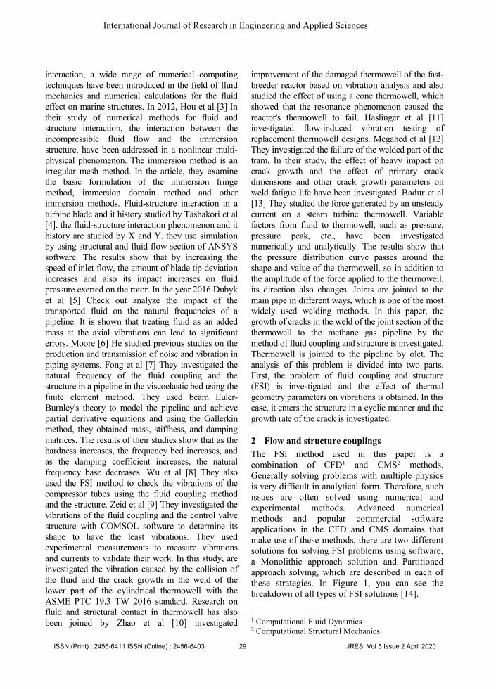
(6). The pressure contour is seen in Figure 3 in
the fluid passing through the pipe and the stress
contour in the thermowell set (including the
thermowell, flange, thermowell tube, olet and
welds). In Figure 2, the thermowell set has 3
welds. The greatest amount of stress is created
in the lower weld, which connects the
thermowell to the main pipe by the olet. Figure
4 shows the concentration of the stress in the
welding section that first connects to the main
pipeline. Therefore, it is better to investigate
the growth of cracks at this weld surface. One
of the most important factors in thermowell
vibrations and as a result of crack propagation
is the geometric properties of the thermowell. It
is shown that the thickness of the thermowell
wall in these cases is 3 mm, which the outer
diameter is 6 mm more than the values
mentioned.
Fig. 8. Pressure contour in fluid and stress contour.
Fig. 9. Stress contour at weld olet joint to the main
pipe.
A- Frequency changes with internal radius change.
ISSN (Print) : 2456-6411 ISSN (Online) : 2456-6403 33 JRES, Vol 5 Issue 2 April 2020
International Journal of Research in Engineering and Applied Sciences

B- Maximum displacement change with internal radius
change.
Fig. 10. Frequency and maximum displacement
changes with internal radius changes.
A- Frequency changes with thickness of the tube change.
B- Maximum displacement change with thickness of the
tube change.
Fig. 11. Frequency changes and maximum
displacement by changing the thickness of the tube.
One of the most important geometric properties of
a thermowell is its longitudinal vibration (L * in
Figure 1). The frequency of the thermowell is
reduced. Figure 12 Frequency change and
maximum displacement by changing the height of
the thermowell (the part that is inside the pipeline)
and Fluid conditions also affect the amount of
vibration, in Figure 13. Changing in the ratio of the
main frequency to the original natural frequency at
different inlet speeds of the fluid in shown Figure
13. which decreases with increasing gas velocity.
Figure 9. Frequency and maximum displacement
changes with internal radius changes and Figure 11
shows the variation of natural frequencies for
various thicknesses of the pipe wall to an internal
radius of 3.5 mm. As the thickness of the tube
increases, the hardness increases, so the natural
frequency increases, which is shown in the
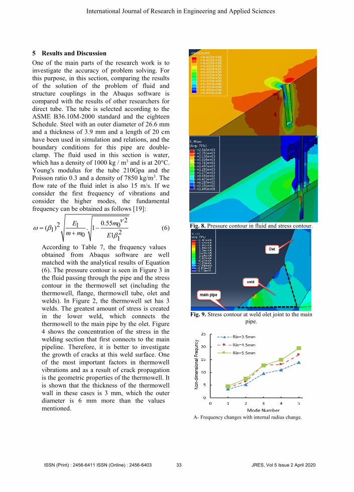
diagram. The normal residue diagram and
frequency change and maximum displacement by
changing the height of the thermowell (the part
that is inside the pipeline) shown in Figure 14.
Fig.12. Frequency change and maximum
displacement.
Fig. 13. Changing in the ratio of the main
frequency.
A- Normal residuals of Maximum displacement
ISSN (Print) : 2456-6411 ISSN (Online) : 2456-6403 34 JRES, Vol 5 Issue 2 April 2020
International Journal of Research in Engineering and Applied Sciences
B- Normal residuals of frequency
Fig. 14. Normal plot of residual.
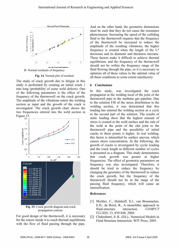
The study of crack growth due to fatigue in this
study is performed by creating an initial crack 1
mm long (probability of some weld defects). One
of the following parameters is the effect of the
frequency of the thermowell on the crack growth.
The amplitude of the vibrations enters the welding
section as input and the growth of the crack is
investigated. The crack growth chart shows the
two frequencies entered into the weld section in
Figure 15.
Fig. 15. Crack growth diagram and crack
propagation contour.
For good design of the thermowell, it is necessary
for the sensor inside it to reach thermal equilibrium
with the flow of fluid passing through the pipe.
And on the other hand, the geometric dimensions
must be such that they do not cause the resonance
phenomenon. Increasing the speed of the colliding
fluid to the thermowell requires that the frequency
of the thermowell be increased to reduce the
amplitude of the resulting vibrations, the higher
frequency is created when the length of the L*
decreases and its diameter and thickness increase.
These factors make it difficult to achieve thermal
equilibrium, and the frequency of the thermowell
should not be within the frequency range of the
fluid flowing through the pipe, so it is necessary to
optimize all of these values to the optimal value of
all these conditions to some extent satisfactory.
6 Conclusions
In this study, was investigated the crack
propagation at the welding local of the joint of the
thermowell pipe to the methane gas pipeline. Due
to the solution FSI of the stress distribution in the
welding section, it was determined that this
loading has entered the welding section as a cycle
in the second part of the solution. The results of
static loading show that the highest amount of
stress is created at the weld surface and the side of
the weld at the point of the olet joint to the
thermowell pipe and the possibility of initial
cracks in these points is higher. In real welding,
this factor is intensified by surface uneven, which
causes stress concentration. In the following, the
growth of cracks is investigated by cyclic loading
and the crack length in different number of cycles
is presented as a diagram. This study demonstrates
that crack growth was greater at higher
frequencies. The effect of geometric parameters on
frequency was also investigated. Therefore, it
should be tried to reduce the frequency by
changing the geometry of the thermowell to reduce
the crack growth, but the frequency of the
thermowell should not be in the range of the
passing fluid frequency, which will cause an
intensification.
References
[1] Michler, C., Hulshoff, S.J., van Brummelen,
E.H., de Borst, R., A monolithic approach to
fluid-structure interaction. COMPUT
FLUIDS, 33, 839-848, 2004.
[2] Chakrabarti, S. K. (Ed.)., Numerical Models in
Fluid Structure Interaction. WIT Press, 2005.
ISSN (Print) : 2456-6411 ISSN (Online) : 2456-6403 35 JRES, Vol 5 Issue 2 April 2020
International Journal of Research in Engineering and Applied Sciences

[3] Hou, G., Wang, J., Layton, A., Numerical
Methods for Fluid-Structure Interaction. A
Review. Vol. 12, No. 2, 337-377, 2012.
[4] Tashakori, B. M., Elhami, M., Rabiee, A.,
Numerical Analysis of Fluid Structure
Interaction Phenomenon on a Turbine Blade.
Fluid Mechanics and Aerodynamics Journal,
Volume 4, Number 2, 1-11, 2016.
[5] Dubyk, I. R., Orynyak, I. V., Fluid-Structure
Interaction in Free Vibration Analysis of
Pipelines. Scientific Journal of the Ternopil
National Technical University No 1(81), 2016.
[6] Moore, S., A review of noise and vibration in
fluid-filled pipe systems. Proceedings of
ACOUSTICS9-11 November, Brisbane,
Australia, 2016.
[7] Fong, K. S., Yassin, A. Y. M., Fluid-Structure
Interaction (FSI) of Damped Oil Conveying
Pipeline System by Finite Element
Method. MATEC Web of Conferences. Vol.
111. EDP Sciences, 2017.
[8] Wu, J. A. R. I., Olsson, S. I. M. O. N., Fluid
structure interaction analysis on the
aerodynamic performance of underbody
panels. Master's thesis in fluid and solid
mechanics, Chalmers University of
Technology Goteborg, Sweden, 2014.
[9] Zeid, A., & Shouman, M. Flow-Induced
Vibration on the Control Valve with a
Different
Concave Plug Shape Using FSI
Simulation. Shock and Vibration, 2019.
[10] Aoi, H., Zhao, Y., & Hayase, T. Improvement
of the damaged thermowell of the fast-breeder
reactor based on vibration
analysis. Simulation, 78(8), 504-511.Raja, R.
S., 2012.
[11] Haslinger, K. H. Flow-induced vibration
testing of replacement thermowell
designs. Journal of fluids and
structures, 18(3-4), 425-440, 2003.
[12] Megahed, M. M., & Attia, M. S. Failure
analysis of thermowell weldment
cracking. Engineering Failure Analysis, 50,
51-61, 2015.
[13] Badur, J., Kornet, S., Sławiński, D., &
Ziółkowski, P. Analysis of unsteady flow
forces acting on the thermowell in a steam
turbine control stage. In Journal of Physics:
Conference Series (Vol. 760, No. 1, p.
012001). IOP Publishing, 2016.
[14] Kesti, J. A. R. I., Olsson, S. I. M. O. N. Fluid
structureinteraction analysis on the
aerodynamic performance of underbody
panels. Master's thesis in fluid and solid
mechanics, Chalmers University of
Technology Goteborg, Sweden, 2014.
[15] Raja, R. S. Coupled fluid structure interaction
analysis on a cylinder exposed to ocean wave
loading. Chalmers University of Technology,
Göteborg, Sweden, 2012.
[16] Khoei, A. R. Extended finite element method:
theory and applications. John Wiley & Sons,
2014.
[17] Simulia, D. S. Abaqus Analysis User’s Guide,
v. 6.13. Johnston, RI, 2013.
[18] Moslemi Petrudi, A., Kamyab, M. H.,
Vahedi,Kh, “Study and Analysis of the Crack
Initial Mechanism and Critical Fatigue
Fractures of High-Strength Steels in Aerial
Structures”, 5th International Conference on
Science and Technology, Iran, 2019.
[19] Yi-Min, H., Yong-Shou, L., Bao-Hui, L., Yan-
Jiang, L., Zhu-Feng, Y., Natural frequency
analysis of fluid conveying pipeline with
different boundary conditions. NUCL ENG
DES. 240.3, 461-467, 2010.
ISSN (Print) : 2456-6411 ISSN (Online) : 2456-6403 36 JRES, Vol 5 Issue 2 April 2020
International Journal of Research in Engineering and Applied Sciences

Table 1. Weld material preoperties.
Table 2. Mechanical properties of main pipe.
OD(mm) Wall(mm) K(w/mk) (Kg/m3)ρ C ʋ E(GPa)
1016 20.6 700 7800 0.45 0.3 206
Table 3. Olet and Flange material properties.
(MPa)α K C (Kg/m3)ρ ʋ E(GPa)
44 623 447 7861 0.29 250
Table 4. CH4 properties.
Cinematic
viscosity
Dynamic
viscosity P(bar) Vin(m/s) Cp Cv ρ
0.556 13.628 44 3 2.56 1.898 24.5136
Table 5. Thermowell properties.
K α (Kg/m3)ρ ʋ E(GPa)
16.3-21.5 15.9-17.5 8000 0.3 193
Table 6. System operation conditions.
P(bar)Vin(m/s)C)oT(
44335
Table 7. Compare the frequency results obtained in Abaqus and Matlab (equation 6) for direct pipe.
Mode 1 2 3 4 5 6
Abaqus Empty
Pipe 37.51 103.15 201.53 331.73 493.06 684.64
MATLAB
Water-Filled
Pipe
28.58 85.34 159.86 290.02 412.36 567.28
Abaqus Water-
Filled Pipe 29.36 85.57 157.11 288.04 415.47 560.47
Error (%) 2.6 0.266 1.72 0.68 0.75 1.4
(Kg/m3)ρ Fatigue(MPa) ʋ E(GPa)
7700 275 0.3 200
ISSN (Print) : 2456-6411 ISSN (Online) : 2456-6403 37 JRES, Vol 5 Issue 2 April 2020