INVESTIGATE AND OPTIMIZE THE VIVALDI …eprints.utem.edu.my/17995/1/Investigate And Optimize...
24
INVESTIGATE AND OPTIMIZE THE VIVALDI ANTENNA FOR ULTRA- WIDEBAND APPLICATIONS LIM CHIA ROENG This Report Is Submitted In Partial Fulfilment of Requirements for the Bachelor Degree of Electronic Engineering (Wireless Communication) Faculty of Electronic and Computer Engineering Universiti Teknikal Malaysia Melaka JUNE 2016
Transcript of INVESTIGATE AND OPTIMIZE THE VIVALDI …eprints.utem.edu.my/17995/1/Investigate And Optimize...

INVESTIGATE AND OPTIMIZE THE VIVALDI ANTENNA FOR ULTRA-WIDEBAND APPLICATIONS
LIM CHIA ROENG
This Report Is Submitted In Partial Fulfilment of Requirements for the BachelorDegree of Electronic Engineering (Wireless Communication)
Faculty of Electronic and Computer Engineering
Universiti Teknikal Malaysia Melaka
JUNE 2016

ii
UNIVERSTI TEKNIKAL MALAYSIA MELAKA FAKULTI KEJURUTERAAN ELEKTRONIK DAN KEJURUTERAAN KOMPUTER
BORANG PENGESAHAN STATUS LAPORAN
PROJEK SARJANA MUDA II
Tajuk Projek : INVESTIGATE AND OPTIMIZE VIVALDI ANTENNA
FOR ULTRA-WIDEBAND APPLICATION
Sesi Pengajian :
1 5 / 1 6
Saya …………LIM CHIA ROENG……………………………………………………………………….. mengaku membenarkan Laporan Projek Sarjana Muda ini disimpan di Perpustakaan dengan syarat-syarat kegunaan seperti berikut:
1. Laporan adalah hakmilik Universiti Teknikal Malaysia Melaka.
2. Perpustakaan dibenarkan membuat salinan untuk tujuan pengajian sahaja.
3. Perpustakaan dibenarkan membuat salinan laporan ini sebagai bahan pertukaran antara institusi
pengajian tinggi.
4. Sila tandakan ( √ ) :
SULIT*
*(Mengandungi maklumat yang berdarjah keselamatan atau
kepentingan Malaysia seperti yang termaktub di dalam AKTA RAHSIA RASMI 1972)
TERHAD**
**(Mengandungi maklumat terhad yang telah ditentukan oleh
organisasi/badan di mana penyelidikan dijalankan)
TIDAK TERHAD
Disahkan oleh:
________________________ ___________________________________ (TANDATANGAN PENULIS) (COP DAN TANDATANGAN PENYELIA)
Tarikh: ……………………….. Tarikh: ………………………..

iii
“I hereby declare that the work in this project is my own except for summaries and quotations which have been duly acknowledge.”
Signature : ....................................................... Author : LIM CHIA ROENG Date : .......................................................

iv
“I acknowledge that I have read this report and in my opinion this report is sufficient in term of scope and quality for the award of Bachelor of Electronic Engineering
(Wireless Communication) with Honours.”
Signature : ....................................................... Supervisor’s Name : MADAM NORBAYAH BINTI YUSOP Date : .......................................................

v
To my beloved friends and family. Thank you my supervisor and all lecturers who guide me,
and to all my friends for giving me mentally and moral support during process of finish final
year project.

vi
ACKNOWLEDGEMENT
I would like to express my deepest appreciation to all those who provided me the
possibility to complete this report. A special gratitude I give to my supervisor, Madam
Norbayah Binti Yusop and co-supervisor, Dr. Mohd Azlishah Bin Othman who had given me
many learning opportunities throughout the preparation of this report. Besides giving me
suggestions, they had also helped me to coordinate my project, especially in writing this report.
I am highly indebted to Madame Norbayah for her guidance and constant supervision as well
as for accessing my progress and also for her support in completing this report.
Furthermore, I would also like to acknowledge with much appreciation of my friends
for providing decent suggestions and necessary information during the completion of this
report.
I have taken efforts in this project. However, it would not have been possible without
the kind support and help of many individuals. I would like to extend my sincere thanks to all
of them. Last but not least, I would like to thank my parents and family for their support
financially and emotionally.
vii
ABSTRACT
An exponentially tapered slot line antenna named the Vivaldi is studied in this thesis.
This antenna has Ultra-Wideband (UWB) characteristics and is used in applications ranging
from feeds reflectors to microwave imaging. In this project, a Vivaldi antenna with different
dimensions of feedline and substrate are designed and presented. The optimization of Vivaldi
antenna used to improve the basic antenna parameters. Besides that, the Antipodal Vivaldi
antenna is studied and modified in order to improve the return loss and gain of the antenna.
The Computer Simulation Technology (CST) software is used in design the antenna. The
proposed antenna will cover the frequency range from 3.1 GHz to 10.6 GHz. The
characteristics of UWB antenna will be proved from the radiation pattern of the proposed
antenna.
Keywords: Ultra-Wideband, Antipodal Vivaldi Antenna, return loss, gain

viii
ABSTRAK
Dalam tesis ini, antena jenis garis slot tirus yang bernama Vivaldi telah diperkenalkan.
Antenna tersebut mempunyai ciri-ciri Ultra Wideband (UWB) dan digunakan dalam aplikasi
antara julat frekuensi UWB contohnya dalam pengimejan microwave. Pelbagai jenis dimensi
dari segi feedline dan substrat untuk antena Vivaldi telah direka dan dibentangkan dalam tesis
tersebut. Antena Vivaldi yang telah beroptimum tersebut untuk meningkat asas parameter
antena dari segi return loss dan gain. Selain itu, perisian Computer Simulation Technology
(CST) telah digunakan dalam mereka antenna tersebut. Antena yang telah dicadangkan
meliputi julat frekuensi dari 3.1 GHz ke 10.6 GHz. Ciri-ciri antena UWB telah dibukti dari segi
corak radiasi bagi antena tersebut.

ix
TABLE OF CONTENTS
CHAPTER TITLE PAGE
PROJECT TITLE i
REPORT STATUS APPROVAL FORM ii
DECLARATION iii
SUPERVISOR APPROVAL iv
DEDICATION v
ACKNOWLEDGEMENT vi
ABSTRACT vii
ABSTRAK viii
TABLE OF CONTENT ix
LIST OF FIGURES xii
LIST OF TABLES xv
LIST OF ABBREVIATION xvi
I INTRODUCTION
1.1 INTRODUCTION 1
1.2 BACKGROUND 1
1.3 PROBLEM STATEMENT 4
1.4 SIGNIFICANCE OF STUDY 5
1.5 OBJECTIVES OF STUDY 5
1.6 SCOPE OF PROJECT 6

x
1.7 THESIS OUTLINE 6
II LITERATURE REVIEW
2.1 INTRODUCTION 8
2.2 BASIC ANTENNA PARAMETER 8
2.2.1 RADIATION PATTERN 9
2.2.2 BANDWIDTH 11
2.2.3 DIRECTIVITY AND GAIN 12
2.3 TAPERED SLOT ANTENNA (TSA) 12
2.3.1 TAPER PROFILE 12
2.3.2 SUBSTRATE MATERIAL 13
2.4 BASIC GEOMETRY OF VIVALDI ANTENNA 14
2.5 MICROSTRIP/ STRIPLINE TO SLOTLINE TRANSITIONS 15
2.6 ANTIPODAL VIVALDI ANTENNA 16
2.7 BALANCED ANTIPODAL VIVALDI ANTENNA 17
2.8 EVALUATION NOTES
2.8.1 TAPERED SLOT VIVALDI ANTENNA
2.8.8.1 INFLUENCE OF THE EXPONENTIAL
CURVATURE
2.8.1.2 USING SPLINE CURVES FOR TAPER
DEFINITION
2.8.1.3 INFLUENCE OF THE ANTENNA
DIMENSIONS
2.8.1.4 INFLUENCE OF THE ROUND CORNERS
2.8.1.5 COMB STRUCTURE
2.8.1.6 HYBRID EXPONENTIAL MODEL
2.8.2 ANTIPODAL VIVALDI ANTENNA
2.8.2.1 INFLUENCE OF THE INNER
CURVATURE PROFILE
2.8.2.2 USING SPLINE CURVES FOR INNER
19
19
20
22
22
24
25
27
27
28
29

xi
PROFILE
2.8.2.3 INFLUENCE OF THE OUTER
CURVATURE PROFILE
2.8.2.4 INFLUENCE OF THE FIN WIDTH
2.8.2.5 INFLUENCE OF THE CORNERS
29
30
31
III RESEARCH METHODOLOGY
3.1 INTRODUCTION 33
3.2 METHOD 33
3.3 SIMULATION 35
3.3.1 CST 2014 MICROWAVE STUDIO SUITE 35
3.4 PRELIMINARY PREPARATION 35
3.5 DESIGN PARAMETER AND LAYOUT 36
IV RESULTS AND DISCUSSIONS
4.1 INTRODUCTION 37
4.2 WIDTH OF FEEDLINE 38
4.3 WIDTH OF SUBSTRATE 43
4.4 LENGTH OF SUBSTRATE 48
V CONCLUSION AND RECOMMENDATION
5.1 CONCLUSION 53
5.2 FUTURE WORK 54
REFERENCES 56
xii
LIST OF FIGURES
NO TITLE PAGE 1.1 Difference between compressed signals in time domain to the one
expanded in time domain 2
1.2 FCC spectral masks for outdoor unlicensed UWB emission 3 2.1 Three dimensional coordinate system 10 2.2 Radiation Pattern 10 2.3 Three basic taper profiles 13 2.4 Basic geometry shape of the Vivaldi Antenna 14 2.5 Microstrip line to slotline transition 15 2.6 Microstrip to slotline transition with radial stub 16 2.7 Structure of Antipodal Vivaldi Antenna 17 2.8 Cross sectional view of the top of the antipodal Vivaldi and the
skew in electric field across the slot of the antenna 18
2.9 Balanced Antipodal Vivaldi Antenna 18 2.10 Cross sectional view of the top of the balanced antipodal Vivaldi
depicting the resultant E-field across the slot of the antenna 19
2.11 Schema of the tapered slot Vivaldi antenna design and variables 20 2.12 Taper profiles and signals reflected from the structure for various
settings of parameter p 21
2.13 Return loss and fidelity factor F for various settings of parameter p 21 2.14 Return loss and reflected signal for various settings of aperture
width aw 23
2.15 Round Corner design and reflected signal for various settings of corner radius R
24
2.16 Return loss and signal level received at the back probe for various settings of corner radius R
25
2.17 Two investigated comb structures – capacitive comb and resistive comb
26
2.18 Return loss and signal level received at the front probe for both comb structures
26
2.19 Hybrid taper design, description of antipodal design and its variables
27

xiii
2.20 Inner curvature profiles and signals reflected from the structure for various settings of parameter p1.
28
2.21 Return loss and fidelity factor F for various settings of parameter p1.
29
2.22 Outer curvature profiles and signals reflected from the structure for various settings of parameter p2
30
2.23 Return loss and signals reflected from the structure for various settings of parameter L2
31
2.24 Antipodal round corner design and reflected signal for various settings of corner radius R
31
2.25 Return loss and fidelity factor F for various settings of corner radius R
32
3.1 Flow chart of design process 34 3.2 Basic Structure and parameters of Antipodal Vivaldi Antenna 36 4.1 Return Loss with varied width (a) 3.2 mm, (b) 4.2 mm and (c) 5.2
mm 38
4.2 VSWR with varied width (a) 3.2 mm, (b) 4.2 mm and (c) 5.2 mm 39 4.3 Gain with feedline width 3.2 mm 41 4.4 Gain with feedline width 4.2 mm 41 4.5 Gain with feedline width 5.2 mm 42 4.6 Return Loss with varied width (a) 100 mm, (b) 90 mm and (c) 80
mm 43
4.7 VSWR with varied width (a) 100 mm, (b) 90 mm and (c) 80 mm 44 4.8 Gain with substrate width 100 mm 46 4.9 Gain with substrate width 90 mm 46 4.10 Gain with substrate width 80 mm 47 4.11 Return Loss with varied length (a) 95 mm, (b) 90 mm and (c) 80
mm 48
4.12 VSWR with varied length (a) 95 mm, (b) 90 mm and (c) 80 mm 49 4.13 Gain with Substrate Length 95 mm 51 4.14 Gain with Substrate Length 90 mm 51 4.15 Gain with Substrate Length 85 mm 51

xiv
LIST OF TABLE
NO TITLE PAGE 3.1 The dimension of Proposed Antenna 36 4.1 Return Loss with varied width (a) 3.2 mm, (b) 4.2 mm and (c) 5.2
mm 39
4.2 VSWR with varied width (a) 3.2 mm, (b) 4.2 mm and (c) 5.2 mm 40 4.3 Gain of antenna with varied width (a) 3.2 mm, (b) 4.2 mm and (c)
5.2 mm 42
4.4 Return Loss with varied width (a) 100 mm, (b) 90 mm and (c) 80 mm
44
4.5 VSWR with varied width (a) 100 mm, (b) 90 mm and (c) 80 mm 45 4.6 Gains with varied width (a) 100 mm, (b) 90 mm and (c) 80 mm 47 4.7 Return Loss with varied length (a) 95 mm, (b) 90 mm and (c) 80
mm 48
4.8 VSWR with varied length (a) 95 mm, (b) 90 mm and (c) 80 mm 50 4.9 Gain with varied length (a) 95 mm, (b) 90 mm and (c) 80 mm 52
xv
LIST OF ABBREVIATION
UWB - Ultra-Wideband
FCC - Federal Communications Commission
PSD - Power Spectral Density
CST - Computer Simulation Technology
HPBW - Half Power Beamwidth
VSWR - Voltage Standing Wave Ratio
TSA - Tapered Slot Antenna
BAVA - Balanced Antipodal Vivaldi Antenna

1
CHAPTER 1
INTRODUCTION
1.1 INTRODUCTION
In this chapter, Vivaldi antenna for Ultra Wideband (UWB) application will be
discussed. The Ultra Wideband technology also will be briefly explained. A summary
and the aim of this project will also be presented and discussed in this section.
1.2 BACKGROUND
Nowadays, the speed of expanding technology in this generation become faster
compare to pass decade. The limitation of frequency spectrum become the factors in
expanding of technology due to the innovation of new applications. The Ultra Wide
Band is introduced to overcome this problems. UWB is a technology which transfer
2
the data at low spreading of radio energy. The transmission of data has very low power
spectral densities over the wide band frequencies. This low power spectral densities is
useful in the limitation of interference between the radio systems. Due to the higher or
wider bandwidth, a very high data throughput is allowed for the communication
devices with high precision for location or imaging devices [1]. Ultra Wideband radio
transmission is a revolutionary approach in wireless communication field in the sense
that it transmits and receives pulse based waveforms compressed in time domain rather
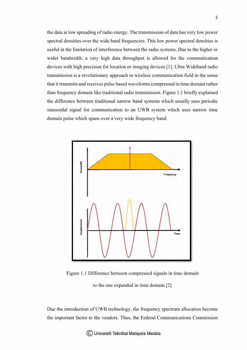
than frequency domain like traditional radio transmission. Figure 1.1 briefly explained
the difference between traditional narrow band systems which usually uses periodic
sinusoidal signal for communication to an UWB system which uses narrow time
domain pulse which spans over a very wide frequency band.
Figure 1.1 Difference between compressed signals in time domain
to the one expanded in time domain [2]
Due the introduction of UWB technology, the frequency spectrum allocation become
the important factor to the vendors. Thus, the Federal Communications Commission

3
(FCC) has allocated the unlicensed frequency band in the range of 3.1 GHz to 10.6
GHz for UWB applications in February 2004. The allocation of the unlicensed band
giving benefits to the UWB technology. Due to this factor, there is a lot of investors
being attracted from various fields and opened the doors for the development of
numerous daily life applications based on the UWB technology.
In addition, the UWB technology is referred to the application which has an
absolute bandwidth more than 500 MHz. In other words, it can be said the system has
a relative bandwidth of greater than twenty five percent. For example, an UWB signal
centred at 2 GHz would have a minimum bandwidth of 500 MHz and minimum
bandwidth at 4 GHz would be 1 GHz. This large spread in frequency domain results
in low level of power spectral density (PSD) as depicted in Figure 1.2. This low level
of PSD ensures the peaceful coexistence of UWB systems with narrowband systems
operating in the same frequency range [3].
Figure 1.2 FCC spectral masks for outdoor unlicensed UWB emission [3]
UWB system has wide impedance bandwidth, steady directional or omnidirectional
radiation pattern, constant gain in desired direction, constant desired polarization, high

4
radiation efficiency, linear phase response, Small size, low profile and embeddable,
low cost and low complexity (installation, fabrication, materials and maintenance).
UWB systems operate at low power transmission levels; channel capacity is proportion
to the bandwidth.
Due to the characteristics of the UWB antennas, this project had been focused
on Antipodal Vivaldi antennas. Antipodal Vivaldi antenna is one of member of taper
slot antenna which functioning as end fire and traveling wave antenna to produce a
directive radiation or omni-directional radiation pattern. The wider pattern bandwidth
and impedance will make the Vivaldi antenna as a traveling wave antenna. Besides
that, the Printed Vivaldi antennas are easy to fabricate, having no highly sensitive
dimensional tolerances. In theoretical, the Vivaldi antenna can be said has an infinity
absolute bandwidth, but it will limits by its physical size and the fabrication capability.
In practice, one of the main bandwidth limitations is the microstrip feeding technique.
1.3 PROBLEM STATEMENT
There are a few types of UWB antenna that widely used in wireless application.
P.J. Gibson was the first introduced Vivaldi antenna since 1979. There are 3 main
categories of Vivaldi antenna: Coplanar, Antipodal and Balanced antipodal that
common use in UWB application. After few years, the researchers were modified the
co-planar Vivaldi antenna by using different methods. The aim of the modification
antenna was to improve and optimize the antenna parameters. Besides, the shape and
the dimension of exterior surface of antenna will effect on the radiation field. In order
to achieve the UWB frequency, a larger size of antenna will be used. The S11
parameter known as reflection coefficient or return loss is represents how much power
is reflected from the antenna. If S11 is 0 dB, all power is reflected from the antenna
and there is no radiated power. However, S11 is -10 dB, this implies that 3 dB of power
is delivered to the antenna while -7 dB is reflected power. [8] Thus, it is important to
improve the return loss more than -10 dB in order to get greater antenna gain. In other
5
words, the lower gain of antenna will bring to the increase rate of losses during
transmission. The narrower bandwidth is due to the weakness of microstrip patch
antenna. Further, the radiation field of the antenna depends on the shape and dimension
of exterior surface. In order to achieve UWB frequency, larger size antenna will be
used.
1.4 SIGNIFICANCE OF STUDY
The Vivaldi antenna is a member of the class of aperiodic, continuously scaled
and end-fire travelling wave antenna structures. It has the advantage of infinite
operating bandwidth due to its exponentially flares. In practice, it can provide
multioctave operation and is therefore designed under class of UWB antennas. These
antennas are used for several applications such as satellite communication systems,
radio astronomy, microwave imaging, feeds for reflectors and wide-band phased array
systems. Due to its smaller size, low cost, ease to fabricate and no highly sensitive
dimensional tolerance, it has been widely explored in UWB technology. In future, the
antennas of wireless applications in UWB will replace with Vivaldi antenna because
of its advantages. It can be further explore to achieve higher frequency band and the
applications.
1.5 OBJECTIVES OF STUDY
The aim of this project is to investigate and optimize the Vivaldi antenna for
UWB applications. In order to achieve this, some of the objectives need to be an
accomplished:
i. To identify the limitation of key parameters for conventional Vivaldi antenna.
ii. To improve the return loss and gain of antenna.

6
iii. To analyse the simulation results at specific frequencies.
1.6 SCOPE OF PROJECT
The objective of this project is to optimize the Vivaldi antenna for UWB
application. Before design an optimization antenna, firstly we have to do the research
on the Vivaldi antenna in UWB technology. The research is based on the journals from
the internet and library. The focus of this project is to design, simulate, analyse and
compare the simulation results in order to produce an optimize antenna. The software
will be used in design and simulation the antenna is Computer Simulation Technology
(CST). There is few types of Vivaldi antenna is determined through journals from
previous researchers. From the journals, the shape of slot antenna, type of substrate
and antenna parameter will be analysed. Besides that, the improvement technique that
used for the antenna parameter is determined from the journals. A parametric study is
applied to design the optimization of Antipodal Vivaldi antenna in higher gain with
miniature size of the antenna. In addition, Roger RT 5880 is chosen as a substrate with
dielectric constant of 2.2.
1.7 THESIS OUTLINE
This thesis introduces the investigation and optimization of Vivaldi antenna for
UWB application. This overall project will be discussed in five chapters.
In Chapter 1 describes the general idea of the project which includes the
problem statement and project background. The objectives and the scopes of the
project are listed. A short and precise methodology also describes so that objectives
can be achieved.
7
In Chapter 2 introduces the literature review about the previous research of
UWB technology and Vivaldi antenna. The theories of the antenna will be discussed
in this chapter.
In Chapter 3 describes a flow of the steps and methodology based on the time
frame. The modified antenna is designed using CST software. A different dimensions
of feedline and substrate are used in the designed which to differentiate from previous
researchers.
In Chapter 4 describes the simulation results will be analysed at specific
frequencies. In the simulation results, a comparison between the changes of designed
antenna will be discussed.
In Chapter 5 describes the project outcome. The overall conclusion on the
project achievement will be mentioned in this chapter. The recommendation for the
future work also will be described.

8
CHAPTER 2
LITERATURE REVIEW
2.1 INTRODUCTION
In this section, the related previous work done by the researcher will be
analysed and discussed. Besides, the related theoretical part is being explained in detail.
This will help to enhance the understanding of this project and contribute towards the
completion of the project. The previous works done by researchers is one of the factors
for design this project.
2.2 BASIC ANTENNA PARAMETER
Antenna is a device which radiates or receives electromagnetic waves. The
antenna is the transition between a guiding device and free space and it is used to

9
convert the energy of guided wave as efficiently as possible or vice versa. Basically,
the antenna parameters are concerned on radiation pattern, impedance bandwidth,
directivity, efficiency and gain.
2.2.1 RADIATION PATTERN
Radiation pattern is provided the information of how an antenna is directing
the energy. In far-field region, the researcher can indicate the properties of antenna
through its propagation pattern. The propagation pattern of the radiated wave is
illustrated in radiation pattern. The position of any particular point in this region has
its own direction and can determine the directivity of the radiated wave. In radiation
field, electric field and magnetic field are used in determined the pattern. The
magnitude of both fields can be expressed in dB scale.
In Figure 2.1, the shapes and direction of the lobes are shown in three
dimensional coordinates system. The x-z plane is indicated the elevation plane whereas
the x-y plane is indicated the azimuth plane.