INVERTEC 170TX 170TPX & 220TPX - Lincoln...
23
IM2050 10/2016 REV05 INVERTEC 170TX 170TPX & 220TPX OPERATOR’S MANUAL ENGLISH Lincoln Electric Bester Sp. z o.o. ul. Jana III Sobieskiego 19A, 58-263 Bielawa, Poland www.lincolnelectric.eu
-
Upload
truongtram -
Category
Documents
-
view
223 -
download
0
Transcript of INVERTEC 170TX 170TPX & 220TPX - Lincoln...
IM2050 10/2016 REV05
INVERTEC 170TX 170TPX & 220TPX
OPERATOR’S MANUAL
ENGLISH
Lincoln Electric Bester Sp. z o.o. ul. Jana III Sobieskiego 19A, 58-263 Bielawa, Poland
www.lincolnelectric.eu
English English I
Declaration of conformity
Lincoln Electric Bester Sp. z o.o.
Declares that the welding machine:
INVERTEC 170TX INVERTEC 170TPX
conforms to the following directives:
2014/35/EU , 2014/30/EU
and has been designed in compliance with the following standards:
EN 60974-1:2012, EN 60974-3:2014, EN 60974-10:2014
20.04.2016
Piotr Spytek
Operations Director Lincoln Electric Bester Sp. z o.o., ul. Jana III Sobieskiego 19A, 58-263 Bielawa, Poland
02/16
English English II
Declaration of conformity
Lincoln Electric Bester Sp. z o.o.
Declares that the welding machine:
INVERTEC 220TPX
conforms to the following directives:
2014/35/EU , 2014/30/EU
and has been designed in compliance with the following standards:
EN 60974-1:2012, EN 60974-3:2014, EN 60974-10:2014
20.04.2016
Piotr Spytek
Operations Director Lincoln Electric Bester Sp. z o.o., ul. Jana III Sobieskiego 19A, 58-263 Bielawa, Poland
02/16

English English III
12/05
THANKS! For having choosen the QUALITY of the Lincoln Electric products. Please Examine Package and Equipment for Damage. Claims for material damaged in shipment must be notified
immediately to the dealer. For future reference record in the table below your equipment identification information. Model Name, Code &
Serial Number can be found on the machine rating plate.
Model Name:
………………...…………………………….…………………………………………………………………………………………..Code & Serial number:
………………….……………………………………………….. …………………………………………………….……………..
Date & Where Purchased:
…………………………………………………………………... ……………………….…………………………………………..
ENGLISH INDEX Technical Specifications (170TX/TPX) CE model ............................................................................................................ 1 Technical Specifications (170TPX) AUS models ............................................................................................................. 2 Technical Specifications (220TPX) CE and AUS model .................................................................................................. 3 Electromagnetic Compatibility (EMC) for 170TX/TPX ..................................................................................................... 4 Electromagnetic Compatibility (EMC) for 220TPX ........................................................................................................... 5 Safety .............................................................................................................................................................................. 6 Installation and Operator Instructions .............................................................................................................................. 7 WEEE ............................................................................................................................................................................ 19 Spare Parts .................................................................................................................................................................... 19 Electrical Schematic ...................................................................................................................................................... 19 Suggested Accessories ................................................................................................................................................. 19
English English 1
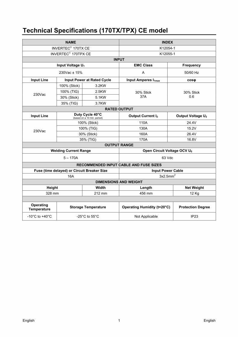
Technical Specifications (170TX/TPX) CE model
NAME INDEX
INVERTEC 170TX CE K12054-1
INVERTEC 170TPX CE K12055-1
INPUT
Input Voltage U1 EMC Class Frequency
230Vac ± 15% A 50/60 Hz
Input Line Input Power at Rated Cycle Input Amperes I1max cosφ
230Vac
100% (Stick) 3.2KW
30% Stick 37A
30% Stick 0.6
100% (TIG) 2.5KW
30% (Stick) 5.1KW
35% (TIG) 3.7KW
RATED OUTPUT
Input Line Duty Cycle 40°C (based on a 10 min. period)
Output Current I2 Output Voltage U2
230Vac
100% (Stick) 110A 24.4V
100% (TIG) 130A 15.2V
30% (Stick) 160A 26.4V
35% (TIG) 170A 16.8V
OUTPUT RANGE
Welding Current Range Open Circuit Voltage OCV U0
5 – 170A 63 Vdc
RECOMMENDED INPUT CABLE AND FUSE SIZES
Fuse (time delayed) or Circuit Breaker Size Input Power Cable
16A 3x2.5mm2
DIMENSIONS AND WEIGHT
Height Width Length Net Weight
328 mm 212 mm 456 mm 12 Kg
Operating Temperature
Storage Temperature Operating Humidity (t=20°C) Protection Degree
-10°C to +40°C -25°C to 55°C Not Applicable IP23
English English 2
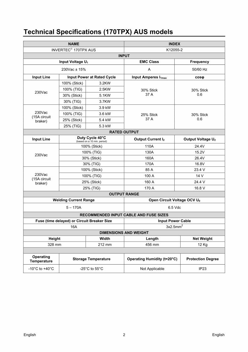
Technical Specifications (170TPX) AUS models
NAME INDEX
INVERTEC 170TPX AUS K12055-2
INPUT
Input Voltage U1 EMC Class Frequency
230Vac ± 15% A 50/60 Hz
Input Line Input Power at Rated Cycle Input Amperes I1max cosφ
230Vac
100% (Stick) 3.2KW
30% Stick 37 A
30% Stick 0.6
100% (TIG) 2.5KW
30% (Stick) 5.1KW
30% (TIG) 3.7KW
230Vac (15A circuit
braker)
100% (Stick) 3.9 kW
25% Stick 37 A
30% Stick 0.6
100% (TIG) 3.6 kW
25% (Stick) 5.4 kW
25% (TIG) 5.3 kW
RATED OUTPUT
Input Line Duty Cycle 40°C (based on a 10 min. period)
Output Current I2 Output Voltage U2
230Vac
100% (Stick) 110A 24.4V
100% (TIG) 130A 15.2V
30% (Stick) 160A 26.4V
30% (TIG) 170A 16.8V
230Vac (15A circuit
braker)
100% (Stick) 85 A 23.4 V
100% (TIG) 100 A 14 V
25% (Stick) 160 A 24.4 V
25% (TIG) 170 A 16.8 V
OUTPUT RANGE
Welding Current Range Open Circuit Voltage OCV U0
5 – 170A 6.5 Vdc
RECOMMENDED INPUT CABLE AND FUSE SIZES
Fuse (time delayed) or Circuit Breaker Size Input Power Cable
16A 3x2.5mm2
DIMENSIONS AND WEIGHT
Height Width Length Net Weight
328 mm 212 mm 456 mm 12 Kg
Operating Temperature
Storage Temperature Operating Humidity (t=20°C) Protection Degree
-10°C to +40°C -25°C to 55°C Not Applicable IP23
English English 3
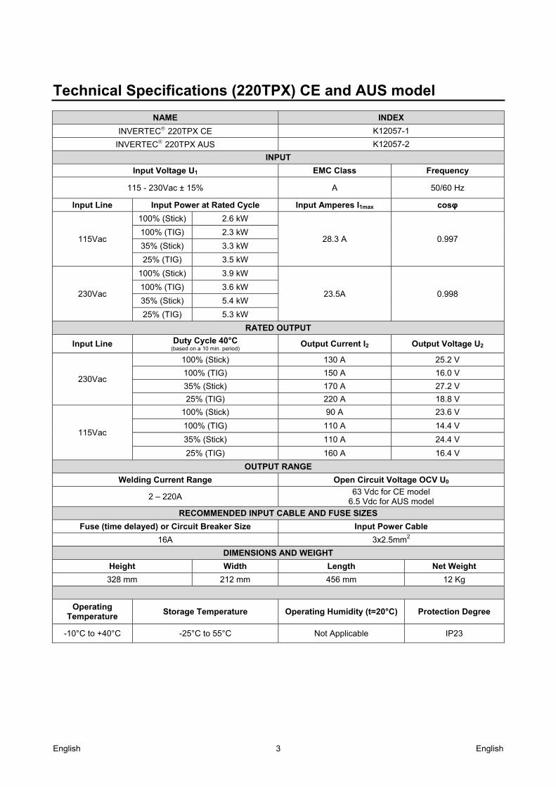
Technical Specifications (220TPX) CE and AUS model
NAME INDEX
INVERTEC 220TPX CE K12057-1
INVERTEC 220TPX AUS K12057-2
INPUT
Input Voltage U1 EMC Class Frequency
115 - 230Vac ± 15% A 50/60 Hz
Input Line Input Power at Rated Cycle Input Amperes I1max cosφ
115Vac
100% (Stick) 2.6 kW
28.3 A 0.997 100% (TIG) 2.3 kW
35% (Stick) 3.3 kW
25% (TIG) 3.5 kW
230Vac
100% (Stick) 3.9 kW
23.5A 0.998 100% (TIG) 3.6 kW
35% (Stick) 5.4 kW
25% (TIG) 5.3 kW
RATED OUTPUT
Input Line Duty Cycle 40°C (based on a 10 min. period)
Output Current I2 Output Voltage U2
230Vac
100% (Stick) 130 A 25.2 V
100% (TIG) 150 A 16.0 V
35% (Stick) 170 A 27.2 V
25% (TIG) 220 A 18.8 V
115Vac
100% (Stick) 90 A 23.6 V
100% (TIG) 110 A 14.4 V
35% (Stick) 110 A 24.4 V
25% (TIG) 160 A 16.4 V
OUTPUT RANGE
Welding Current Range Open Circuit Voltage OCV U0
2 – 220A 63 Vdc for CE model
6.5 Vdc for AUS model
RECOMMENDED INPUT CABLE AND FUSE SIZES
Fuse (time delayed) or Circuit Breaker Size Input Power Cable
16A 3x2.5mm2
DIMENSIONS AND WEIGHT
Height Width Length Net Weight
328 mm 212 mm 456 mm 12 Kg
Operating Temperature
Storage Temperature Operating Humidity (t=20°C) Protection Degree
-10°C to +40°C -25°C to 55°C Not Applicable IP23

English English 4
Electromagnetic Compatibility (EMC) for 170TX/TPX 01/11
This machine has been designed in accordance with all relevant directives and standards. However, it may still generate electromagnetic disturbances that can affect other systems like telecommunications (telephone, radio, and television) or other safety systems. These disturbances can cause safety problems in the affected systems. Read and understand this section to eliminate or reduce the amount of electromagnetic disturbance generated by this machine.
This machine has been designed to operate in an industrial area. The operator must install and operate this equipment as described in this manual. If any electromagnetic disturbances are detected the operator must put in place corrective actions to eliminate these disturbances with, if necessary, assistance from Lincoln Electric. This equipment does not comply with IEC 61000-3-12. If it is connected to a public low-
voltage system, it is responsibility of the installer or user of the equipment to ensure, by consultation with the distribution network operator if necessary, that the equipment may be connected. Before installing the machine, the operator must check the work area for any devices that may malfunction because of electromagnetic disturbances. Consider the following. Input and output cables, control cables, and telephone cables that are in or adjacent to the work area and the
machine. Radio and/or television transmitters and receivers. Computers or computer controlled equipment. Safety and control equipment for industrial processes. Equipment for calibration and measurement. Personal medical devices like pacemakers and hearing aids. Check the electromagnetic immunity for equipment operating in or near the work area. The operator must be sure
that all equipment in the area is compatible. This may require additional protection measures. The dimensions of the work area to consider will depend on the construction of the area and other activities that are
taking place. Consider the following guidelines to reduce electromagnetic emissions from the machine. Connect the machine to the input supply according to this manual. If disturbances occur if may be necessary to take
additional precautions such as filtering the input supply. The output cables should be kept as short as possible and should be positioned together. If possible connect the
work piece to ground in order to reduce the electromagnetic emissions. The operator must check that connecting the work piece to ground does not cause problems or unsafe operating conditions for personnel and equipment.
Shielding of cables in the work area can reduce electromagnetic emissions. This may be necessary for special applications.
WARNING The Class A equipment is not intended for use in residential locations where the electrical power is provided by the public low-voltage supply system. There can be potential difficulties in ensuring electromagnetic compatibility in those locations, due to conducted as well as radio-frequency disturbances.

English English 5
Electromagnetic Compatibility (EMC) for 220TPX 01/11
This machine has been designed in accordance with all relevant directives and standards. However, it may still generate electromagnetic disturbances that can affect other systems like telecommunications (telephone, radio, and television) or other safety systems. These disturbances can cause safety problems in the affected systems. Read and understand this section to eliminate or reduce the amount of electromagnetic disturbance generated by this machine.
This machine has been designed to operate in an industrial area. The operator must install and operate this equipment as described in this manual. If any electromagnetic disturbances are detected the operator must put in place corrective actions to eliminate these disturbances with, if necessary, assistance from Lincoln Electric. This equipment is compliant with EN 61000-3-12 and EN 61000-3-11 if the public low
voltage system impedance at the point of common coupling is lower than 0,322 Ω. It is the responsibility of the installer or user of the equipment to ensure, by consultation with the distribution network operator if necessary, that the system impedance complies with the impedance restrictions. Before installing the machine, the operator must check the work area for any devices that may malfunction because of electromagnetic disturbances. Consider the following. Input and output cables, control cables, and telephone cables that are in or adjacent to the work area and the
machine. Radio and/or television transmitters and receivers. Computers or computer controlled equipment. Safety and control equipment for industrial processes. Equipment for calibration and measurement. Personal medical devices like pacemakers and hearing aids. Check the electromagnetic immunity for equipment operating in or near the work area. The operator must be sure
that all equipment in the area is compatible. This may require additional protection measures. The dimensions of the work area to consider will depend on the construction of the area and other activities that are
taking place. Consider the following guidelines to reduce electromagnetic emissions from the machine. Connect the machine to the input supply according to this manual. If disturbances occur if may be necessary to take
additional precautions such as filtering the input supply. The output cables should be kept as short as possible and should be positioned together. If possible connect the
work piece to ground in order to reduce the electromagnetic emissions. The operator must check that connecting the work piece to ground does not cause problems or unsafe operating conditions for personnel and equipment.
Shielding of cables in the work area can reduce electromagnetic emissions. This may be necessary for special applications.
WARNING The Class A equipment is not intended for use in residential locations where the electrical power is provided by the public low-voltage supply system. There can be potential difficulties in ensuring electromagnetic compatibility in those locations, due to conducted as well as radio-frequency disturbances.
English English 6
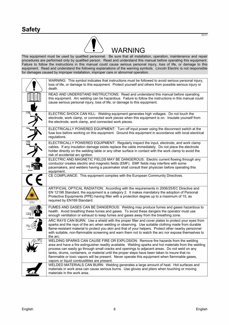
Safety 01/11
WARNING This equipment must be used by qualified personnel. Be sure that all installation, operation, maintenance and repair procedures are performed only by qualified person. Read and understand this manual before operating this equipment. Failure to follow the instructions in this manual could cause serious personal injury, loss of life, or damage to this equipment. Read and understand the following explanations of the warning symbols. Lincoln Electric is not responsible for damages caused by improper installation, improper care or abnormal operation.
WARNING: This symbol indicates that instructions must be followed to avoid serious personal injury, loss of life, or damage to this equipment. Protect yourself and others from possible serious injury or death.
READ AND UNDERSTAND INSTRUCTIONS: Read and understand this manual before operating this equipment. Arc welding can be hazardous. Failure to follow the instructions in this manual could cause serious personal injury, loss of life, or damage to this equipment.
ELECTRIC SHOCK CAN KILL: Welding equipment generates high voltages. Do not touch the electrode, work clamp, or connected work pieces when this equipment is on. Insulate yourself from the electrode, work clamp, and connected work pieces.
ELECTRICALLY POWERED EQUIPMENT: Turn off input power using the disconnect switch at the fuse box before working on this equipment. Ground this equipment in accordance with local electrical regulations.
ELECTRICALLY POWERED EQUIPMENT: Regularly inspect the input, electrode, and work clamp cables. If any insulation damage exists replace the cable immediately. Do not place the electrode holder directly on the welding table or any other surface in contact with the work clamp to avoid the risk of accidental arc ignition.
ELECTRIC AND MAGNETIC FIELDS MAY BE DANGEROUS: Electric current flowing through any conductor creates electric and magnetic fields (EMF). EMF fields may interfere with some pacemakers, and welders having a pacemaker shall consult their physician before operating this equipment.
CE COMPLIANCE: This equipment complies with the European Community Directives.
ARTIFICIAL OPTICAL RADIATION: According with the requirements in 2006/25/EC Directive and EN 12198 Standard, the equipment is a category 2. It makes mandatory the adoption of Personal Protective Equipments (PPE) having filter with a protection degree up to a maximum of 15, as required by EN169 Standard.
FUMES AND GASES CAN BE DANGEROUS: Welding may produce fumes and gases hazardous to health. Avoid breathing these fumes and gases. To avoid these dangers the operator must use enough ventilation or exhaust to keep fumes and gases away from the breathing zone.
ARC RAYS CAN BURN: Use a shield with the proper filter and cover plates to protect your eyes from sparks and the rays of the arc when welding or observing. Use suitable clothing made from durable flame-resistant material to protect you skin and that of your helpers. Protect other nearby personnel with suitable, non-flammable screening and warn them not to watch the arc nor expose themselves to the arc.
WELDING SPARKS CAN CAUSE FIRE OR EXPLOSION: Remove fire hazards from the welding area and have a fire extinguisher readily available. Welding sparks and hot materials from the welding process can easily go through small cracks and openings to adjacent areas. Do not weld on any tanks, drums, containers, or material until the proper steps have been taken to insure that no flammable or toxic vapors will be present. Never operate this equipment when flammable gases, vapors or liquid combustibles are present.
WELDED MATERIALS CAN BURN: Welding generates a large amount of heat. Hot surfaces and materials in work area can cause serious burns. Use gloves and pliers when touching or moving materials in the work area.
English English 7
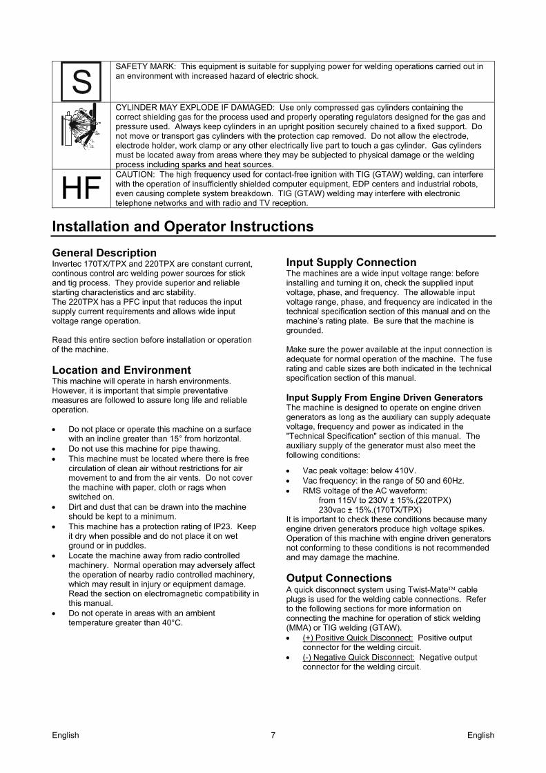
SAFETY MARK: This equipment is suitable for supplying power for welding operations carried out in an environment with increased hazard of electric shock.
CYLINDER MAY EXPLODE IF DAMAGED: Use only compressed gas cylinders containing the correct shielding gas for the process used and properly operating regulators designed for the gas and pressure used. Always keep cylinders in an upright position securely chained to a fixed support. Do not move or transport gas cylinders with the protection cap removed. Do not allow the electrode, electrode holder, work clamp or any other electrically live part to touch a gas cylinder. Gas cylinders must be located away from areas where they may be subjected to physical damage or the welding process including sparks and heat sources.
HF CAUTION: The high frequency used for contact-free ignition with TIG (GTAW) welding, can interfere with the operation of insufficiently shielded computer equipment, EDP centers and industrial robots, even causing complete system breakdown. TIG (GTAW) welding may interfere with electronic telephone networks and with radio and TV reception.
Installation and Operator Instructions
General Description Invertec 170TX/TPX and 220TPX are constant current, continous control arc welding power sources for stick and tig process. They provide superior and reliable starting characteristics and arc stability. The 220TPX has a PFC input that reduces the input supply current requirements and allows wide input voltage range operation. Read this entire section before installation or operation of the machine.
Location and Environment This machine will operate in harsh environments. However, it is important that simple preventative measures are followed to assure long life and reliable operation. Do not place or operate this machine on a surface
with an incline greater than 15° from horizontal. Do not use this machine for pipe thawing. This machine must be located where there is free
circulation of clean air without restrictions for air movement to and from the air vents. Do not cover the machine with paper, cloth or rags when switched on.
Dirt and dust that can be drawn into the machine should be kept to a minimum.
This machine has a protection rating of IP23. Keep it dry when possible and do not place it on wet ground or in puddles.
Locate the machine away from radio controlled machinery. Normal operation may adversely affect the operation of nearby radio controlled machinery, which may result in injury or equipment damage. Read the section on electromagnetic compatibility in this manual.
Do not operate in areas with an ambient temperature greater than 40°C.
Input Supply Connection The machines are a wide input voltage range: before installing and turning it on, check the supplied input voltage, phase, and frequency. The allowable input voltage range, phase, and frequency are indicated in the technical specification section of this manual and on the machine’s rating plate. Be sure that the machine is grounded. Make sure the power available at the input connection is adequate for normal operation of the machine. The fuse rating and cable sizes are both indicated in the technical specification section of this manual. Input Supply From Engine Driven Generators The machine is designed to operate on engine driven generators as long as the auxiliary can supply adequate voltage, frequency and power as indicated in the "Technical Specification" section of this manual. The auxiliary supply of the generator must also meet the following conditions:
Vac peak voltage: below 410V. Vac frequency: in the range of 50 and 60Hz. RMS voltage of the AC waveform: from 115V to 230V ± 15%.(220TPX) 230vac ± 15%.(170TX/TPX) It is important to check these conditions because many engine driven generators produce high voltage spikes. Operation of this machine with engine driven generators not conforming to these conditions is not recommended and may damage the machine.
Output Connections A quick disconnect system using Twist-Mate cable plugs is used for the welding cable connections. Refer to the following sections for more information on connecting the machine for operation of stick welding (MMA) or TIG welding (GTAW). (+) Positive Quick Disconnect: Positive output
connector for the welding circuit. (-) Negative Quick Disconnect: Negative output
connector for the welding circuit.
English English 8
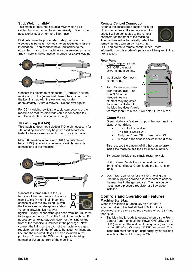
Stick Welding (MMA) This machine does not include a MMA welding kit cables, but may be purchased separately. Refer to the accessories section for more information. First determine the proper electrode polarity for the electrode to be used. Consult the electrode data for this information. Then connect the output cables to the output terminals of the machine for the selected polarity. Shown here is the connection method for DC(+) welding.
Connect the electrode cable to the (+) terminal and the work clamp to the (-) terminal. Insert the connector with the key lining up with the keyway and rotate approximately ¼ turn clockwise. Do not over tighten. For DC(-) welding, switch the cable connections at the machine so that the electrode cable is connected to (-) and the work clamp is connected to (+). TIG Welding (GTAW) This machine does not include a TIG torch necessary for TIG welding, but one may be purchased separately. Refer to the accessories section for more information. Most TIG welding is done with DC(-) polarity shown here. If DC(+) polarity is necessary switch the cable connections at the machine.
Connect the torch cable to the (-) terminal of the machine and the work clamp to the (+) terminal. Insert the connector with the key lining up with the keyway and rotate approximately ¼ turn clockwise. Do not over tighten. Finally, connect the gas hose from the TIG torch to the gas connector (B) on the front of the machine. If necessary, an extra gas connector for the fitting on the front of the machine is included in the package. Next, connect the fitting on the back of the machine to a gas regulator on the cylinder of gas to be used. An input gas line and the required fittings are also included in the package. Connect the TIG torch trigger to the trigger connector (A) on the front of the machine.
Remote Control Connection Refer to the accessories section for a list of remote controls. If a remote control is used, it will be connected to the remote connector on the front of the machine. The machine will automatically detect the remote control, turn on the REMOTE LED, and switch to remote control mode. More information on this mode of operation will be given in the next section. Rear Panel A. Power Switch: It turns
ON / OFF the input power to the machine.
B. Input cable: Connect it
to the mains. C. Fan: Do not obstruct or
filter the fan inlet. The “F.A.N.” (Fan As Needed) feature automatically regulates the speed of thefan. If the Machine doesn’t weld for more than 5 minutes, it will enter Green Mode.
Green Mode Green Mode is a feature that puts the machine in a stand-by condition:
The output is disabled The fan is turned OFF Only the Power ON LED remains ON. A moving red dash is shown in the display
This reduces the amount of dirt that can be drawn inside the Machine and the power consumption. To restore the Machine simply restart to weld. NOTE: Green Mode long time condition: each 10min of continuous Green Mode the fan runs for 1min.
D. Gas Inlet: Connector for the TIG shielding gas.
Use the supplied gas line and connector to connect the machine to the gas source. The gas source must have a pressure regulator and flow gage installed.
Controls and Operational Features Machine Start-Up: When the machine is turned ON an auto-test is executed: during this test all the LEDs turn ON in sequence; at the same time the displays show “333” and then “888”. The Machine is ready to operate when on the Front
Control Panel lights up the “Power ON” LED, the “A” LED (placed on the middle of the synoptic) with one of the LED of the Welding “MODE” command. This is the minimum condition: depending by the welding selection others LEDs may be ON.

English English 9
Front Panel Indicators and Controls Power ON LED:
This LED blinks during the machine start-up and lights up steadily when the machine is ready to operate. If the Input Voltage Overrange protection becomes active, the Power ON LED starts blinking and an error code is shown on the displays. The machine restarts automatically when the Input Voltage returns in the correct range. For further detail read the Error Codes and Troubleshooting section. Remote LED:
This indicator will turn on when a Remote command is connected to the machine via the remote control connector. If a Remote command is connected to the Machine, the Output Current knob operates in two different modes: STICK and TIG:
STICK mode: with a Remote command connected the output of the machine is ON. A
Remote Amptrol or Pedal are allowed (trigger is ignored).
Connecting the Remote command excludes the Output Current Knob of the Machine’s user interface. Through the Remote command is available the full Output Current Range.
TIG mode: in Local and remote mode the
output of the machine is OFF. A Trigger is necessary to enable the output.
The Output Current range selectable from the Remote command depends by the Machine’s user interface Output Current Knob. Eg.: if the Output Current is set to 100A with the Machine’s user interface Output Current Knob, the Remote command will adjust the Output Current from a minimum of 2A to a maximum of 100A. Remote Pedal: For a correct use, the “option 30” must be enabled in the setup menu: 2-step sequence is automatically selected Upslope / Downslope ramps and Restart are
disabled. Spot, Bi-Level and 4-step functions aren’t
selectable (Normal operation is restored when the Remote command is disconnected.)
Thermal LED:
This indicator will turn on when the machine is overheated and the output has been disabled. This normally occurs when the duty cycle of the machine has been exceeded. Leave the machine on to allow the internal components to cool. When the indicator turns off, normal operation is again possible. VRD LED (enabled on Australian Machines only):
This machine is provided by VRD (Voltage Reduction Device) function: this reduces the voltage at the output leads. The VRD function is enabled by factory default only on machines that meet the AS 1674.2 Australian Standards. (C-Tick logo " " on/near the Rating Plate applied on the machine). The VRD LED is ON when the Output Voltage is below 12V with the Machine at idle (no welding time). For others machines this function is disabled (the LED is always OFF).
English English 10
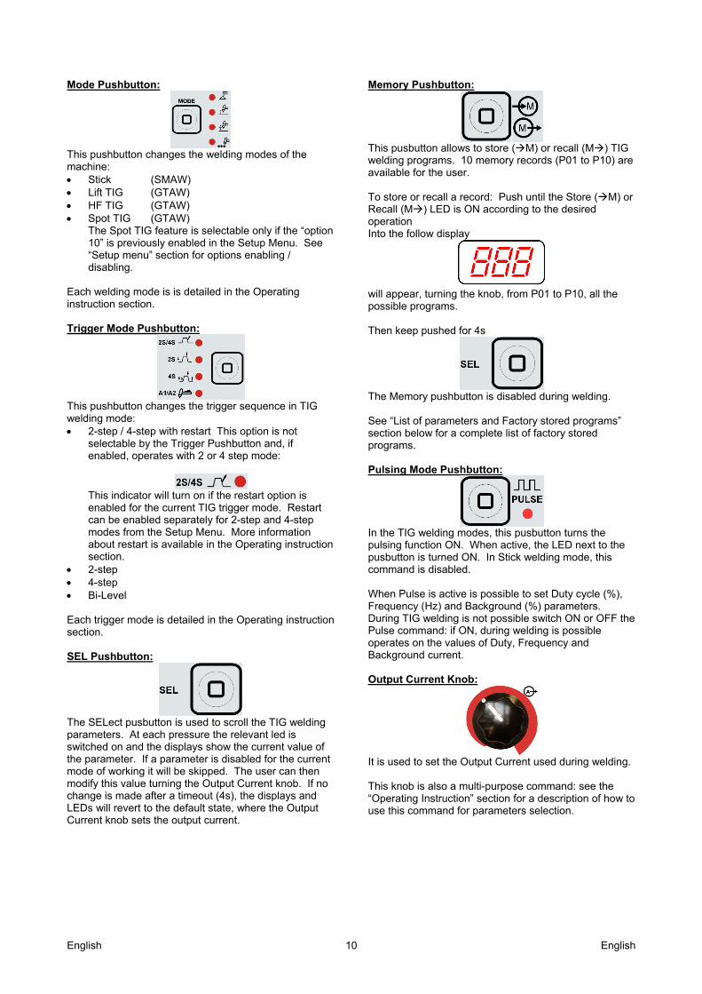
Mode Pushbutton:
This pushbutton changes the welding modes of the machine: Stick (SMAW) Lift TIG (GTAW) HF TIG (GTAW) Spot TIG (GTAW)
The Spot TIG feature is selectable only if the “option 10” is previously enabled in the Setup Menu. See “Setup menu” section for options enabling / disabling.
Each welding mode is is detailed in the Operating instruction section. Trigger Mode Pushbutton:
This pushbutton changes the trigger sequence in TIG welding mode: 2-step / 4-step with restart This option is not
selectable by the Trigger Pushbutton and, if enabled, operates with 2 or 4 step mode:
This indicator will turn on if the restart option is enabled for the current TIG trigger mode. Restart can be enabled separately for 2-step and 4-step modes from the Setup Menu. More information about restart is available in the Operating instruction section.
2-step 4-step Bi-Level Each trigger mode is detailed in the Operating instruction section. SEL Pushbutton:
The SELect pusbutton is used to scroll the TIG welding parameters. At each pressure the relevant led is switched on and the displays show the current value of the parameter. If a parameter is disabled for the current mode of working it will be skipped. The user can then modify this value turning the Output Current knob. If no change is made after a timeout (4s), the displays and LEDs will revert to the default state, where the Output Current knob sets the output current.
Memory Pushbutton:
This pusbutton allows to store (M) or recall (M) TIG welding programs. 10 memory records (P01 to P10) are available for the user. To store or recall a record: Push until the Store (M) or Recall (M) LED is ON according to the desired operation Into the follow display
will appear, turning the knob, from P01 to P10, all the possible programs. Then keep pushed for 4s
The Memory pushbutton is disabled during welding. See “List of parameters and Factory stored programs” section below for a complete list of factory stored programs. Pulsing Mode Pushbutton:
In the TIG welding modes, this pusbutton turns the pulsing function ON. When active, the LED next to the pusbutton is turned ON. In Stick welding mode, this command is disabled. When Pulse is active is possible to set Duty cycle (%), Frequency (Hz) and Background (%) parameters. During TIG welding is not possible switch ON or OFF the Pulse command: if ON, during welding is possible operates on the values of Duty, Frequency and Background current. Output Current Knob:
It is used to set the Output Current used during welding. This knob is also a multi-purpose command: see the “Operating Instruction” section for a description of how to use this command for parameters selection.
English English 11
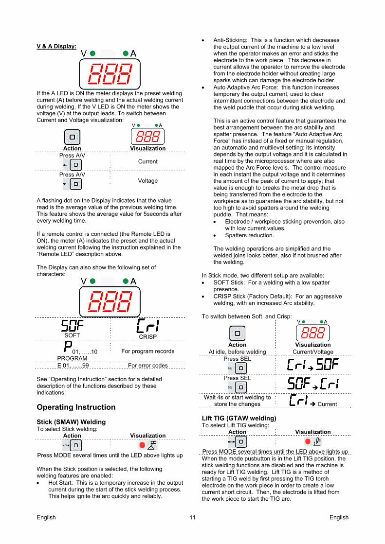
V & A Display:
If the A LED is ON the meter displays the preset welding current (A) before welding and the actual welding current during welding. If the V LED is ON the meter shows the voltage (V) at the output leads. To switch between Current and Voltage visualization:
Action
Visualization
Press A/V
Current
Press A/V
Voltage
A flashing dot on the Display indicates that the value read is the average value of the previous welding time. This feature shows the average value for 5seconds after every welding time. If a remote control is connected (the Remote LED is ON), the meter (A) indicates the preset and the actual welding current following the instruction explained in the “Remote LED” description above. The Display can also show the following set of characters:
SOFT
CRISP
01, …..10 PROGRAM
For program records
E 01, ......99 For error codes See “Operating Instruction” section for a detailed description of the functions described by these indications.
Operating Instruction Stick (SMAW) Welding To select Stick welding:
Action Visualization
Press MODE several times until the LED above lights up When the Stick position is selected, the following welding features are enabled: Hot Start: This is a temporary increase in the output
current during the start of the stick welding process. This helps ignite the arc quickly and reliably.
Anti-Sticking: This is a function which decreases the output current of the machine to a low level when the operator makes an error and sticks the electrode to the work piece. This decrease in current allows the operator to remove the electrode from the electrode holder without creating large sparks which can damage the electrode holder.
Auto Adaptive Arc Force: this function increases temporary the output current, used to clear intermittent connections between the electrode and the weld puddle that occur during stick welding. This is an active control feature that guarantees the best arrangement between the arc stability and spatter presence. The feature "Auto Adaptive Arc Force" has instead of a fixed or manual regulation, an automatic and multilevel setting: its intensity depends by the output voltage and it is calculated in real time by the microprocessor where are also mapped the Arc Force levels. The control measure in each instant the output voltage and it determines the amount of the peak of current to apply; that value is enough to breaks the metal drop that is being transferred from the electrode to the workpiece as to guarantee the arc stability, but not too high to avoid spatters around the welding puddle. That means: Electrode / workpiece sticking prevention, also
with low current values. Spatters reduction. The welding operations are simplified and the welded joins looks better, also if not brushed after the welding.
In Stick mode, two different setup are available: SOFT Stick: For a welding with a low spatter
presence. CRISP Stick (Factory Default): For an aggressive
welding, with an increased Arc stability. To switch between Soft and Crisp:
Action
Visualization
At idle, before welding Current/Voltage Press SEL
Press SEL
Wait 4s or start welding to store the changes Current
Lift TIG (GTAW welding) To select Lift TIG welding:
Action Visualization
Press MODE several times until the LED above lights upWhen the mode pusbutton is in the Lift TIG position, the stick welding functions are disabled and the machine is ready for Lift TIG welding. Lift TIG is a method of starting a TIG weld by first pressing the TIG torch electrode on the work piece in order to create a low current short circuit. Then, the electrode is lifted from the work piece to start the TIG arc.
English English 12
HF TIG (GTAW welding) To select HF TIG welding:
Action Visualization
Press MODE several times until the LED above lights up When the mode pushbutton is in HF TIG position, the stick welding functions are disabled and the machine is ready for HF TIG welding. During the HF TIG mode, the TIG arc is started by HF without pressing the electrode on the work piece. The HF used for starting the TIG arc will remain on for 3 seconds; if the arc is not started in this time limit, the trigger sequence must be restarted. The HF arc start strength can be adjusted in the setup menu by changing the value of option 40. Four arc start strengths are available, ranging from 1 (smooth, suitable for thin electrodes) to 4 (strong, suitable for thick electrodes). The default value for this option is 3. Spot TIG (GTAW welding) The Spot TIG feature is selectable only if the “option 10” is previously enabled in the Setup Menu. To select Spot TIG welding:
Action Visualization
Press MODE several times until the LED above lights up This welding mode is especially thought to tack or weld thin materials. It uses HF start and immediately delivers the set current without any upslope/downslope. The welding time can be either linked to the trigger or set with the spot time control. If the spot time (“option 11” of the Setup Menu) is enabled from the setup menu, in order to change the spot time:
Action
Visualization
At idle, before welding Current/Voltage Press SEL
Spot time
At this point the spot time can be adjusted by turning the Output Current knob. Setting the spot time to 0 will disable the fixed time function and the welding time will be linked to the TIG torch trigger. NOTE: The HF start strength is adjusted by setup option 40, as described in the HF Tig section above. See “Setup menu” section for options enabling / disabling.
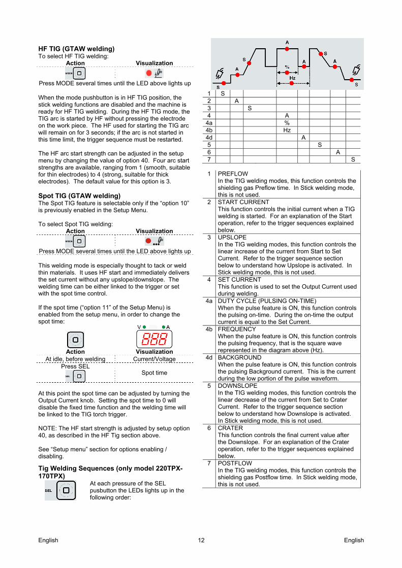
Tig Welding Sequences (only model 220TPX-170TPX)
At each pressure of the SEL pusbutton the LEDs lights up in the following order:
1 S 2 A 3 S 4 A
4a % 4b Hz 4d A 5 S 6 A 7 S
1 PREFLOW In the TIG welding modes, this function controls the shielding gas Preflow time. In Stick welding mode, this is not used.
2 START CURRENT This function controls the initial current when a TIG welding is started. For an explanation of the Start operation, refer to the trigger sequences explained below.
3 UPSLOPE In the TIG welding modes, this function controls the linear increase of the current from Start to Set Current. Refer to the trigger sequence section below to understand how Upslope is activated. In Stick welding mode, this is not used.
4 SET CURRENT This function is used to set the Output Current used during welding.
4a DUTY CYCLE (PULSING ON-TIME) When the pulse feature is ON, this function controls the pulsing on-time. During the on-time the output current is equal to the Set Current.
4b FREQUENCY When the pulse feature is ON, this function controls the pulsing frequency, that is the square wave represented in the diagram above (Hz).
4d BACKGROUND When the pulse feature is ON, this function controls the pulsing Background current. This is the current during the low portion of the pulse waveform.
5 DOWNSLOPE In the TIG welding modes, this function controls the linear decrease of the current from Set to Crater Current. Refer to the trigger sequence section below to understand how Downslope is activated. In Stick welding mode, this is not used.
6 CRATER This function controls the final current value after the Downslope. For an explanation of the Crater operation, refer to the trigger sequences explained below.
7 POSTFLOW In the TIG welding modes, this function controls the shielding gas Postflow time. In Stick welding mode, this is not used.
English English 13
During welding the Sel pushbutton is enabled for the following functions: Output current Only if Pulse Function is active: is possible operates
on the values of Duty (%), Frequency (Hz) and Background current (A).
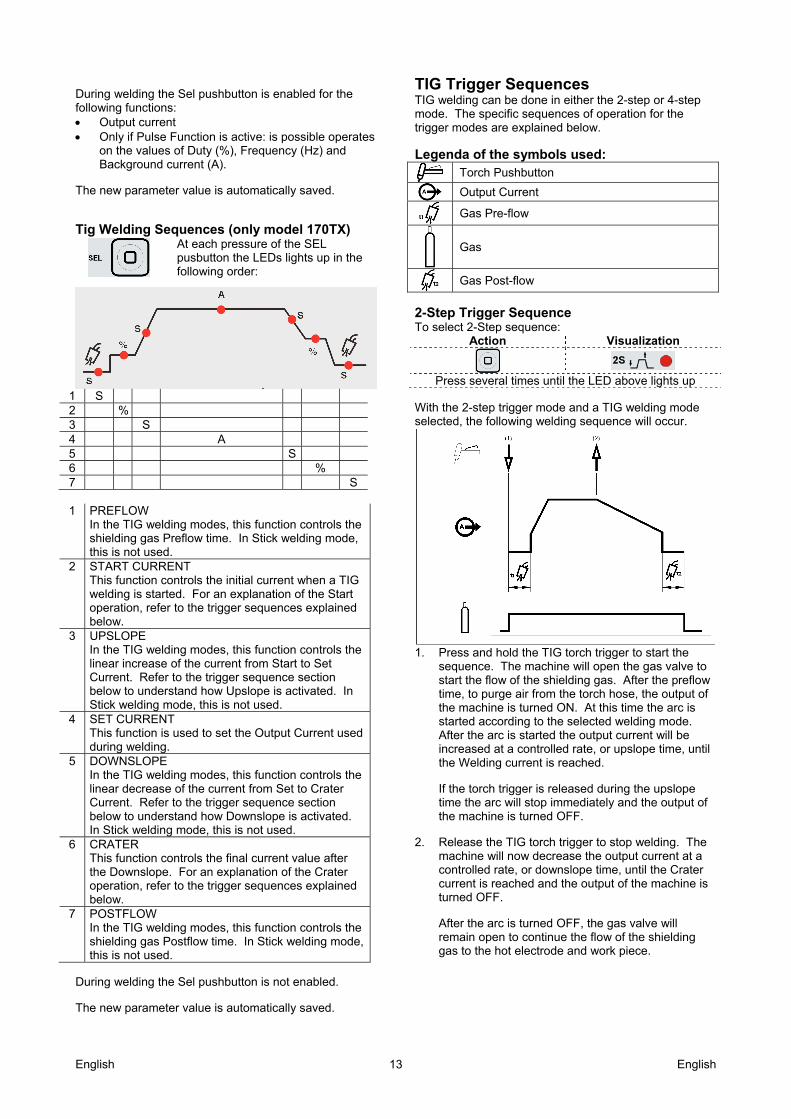
The new parameter value is automatically saved. Tig Welding Sequences (only model 170TX)
At each pressure of the SEL pusbutton the LEDs lights up in the following order:
1 S 2 % 3 S 4 A 5 S 6 % 7 S
1 PREFLOW In the TIG welding modes, this function controls the shielding gas Preflow time. In Stick welding mode, this is not used.
2 START CURRENT This function controls the initial current when a TIG welding is started. For an explanation of the Start operation, refer to the trigger sequences explained below.
3 UPSLOPE In the TIG welding modes, this function controls the linear increase of the current from Start to Set Current. Refer to the trigger sequence section below to understand how Upslope is activated. In Stick welding mode, this is not used.
4 SET CURRENT This function is used to set the Output Current used during welding.
5 DOWNSLOPE In the TIG welding modes, this function controls the linear decrease of the current from Set to Crater Current. Refer to the trigger sequence section below to understand how Downslope is activated. In Stick welding mode, this is not used.
6 CRATER This function controls the final current value after the Downslope. For an explanation of the Crater operation, refer to the trigger sequences explained below.
7 POSTFLOW In the TIG welding modes, this function controls the shielding gas Postflow time. In Stick welding mode, this is not used.
During welding the Sel pushbutton is not enabled. The new parameter value is automatically saved.
TIG Trigger Sequences TIG welding can be done in either the 2-step or 4-step mode. The specific sequences of operation for the trigger modes are explained below.
Legenda of the symbols used: Torch Pushbutton
Output Current
Gas Pre-flow
Gas
Gas Post-flow
2-Step Trigger Sequence To select 2-Step sequence:
Action Visualization
Press several times until the LED above lights up
With the 2-step trigger mode and a TIG welding mode selected, the following welding sequence will occur.
1. Press and hold the TIG torch trigger to start the
sequence. The machine will open the gas valve to start the flow of the shielding gas. After the preflow time, to purge air from the torch hose, the output of the machine is turned ON. At this time the arc is started according to the selected welding mode. After the arc is started the output current will be increased at a controlled rate, or upslope time, until the Welding current is reached. If the torch trigger is released during the upslope time the arc will stop immediately and the output of the machine is turned OFF.
2. Release the TIG torch trigger to stop welding. The
machine will now decrease the output current at a controlled rate, or downslope time, until the Crater current is reached and the output of the machine is turned OFF. After the arc is turned OFF, the gas valve will remain open to continue the flow of the shielding gas to the hot electrode and work piece.
English English 14
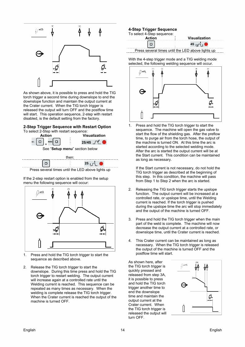
As shown above, it is possible to press and hold the TIG torch trigger a second time during downslope to end the downslope function and maintain the output current at the Crater current. When the TIG torch trigger is released the output will turn OFF and the postflow time will start. This operation sequence, 2-step with restart disabled, is the default setting from the factory. 2-Step Trigger Sequence with Restart Option To select 2-Step with restart sequence:
Action Visualization
+
See “Setup menu” section below
then:
Press several times until the LED above lights up
If the 2-step restart option is enabled from the setup menu the following sequence will occur:
1. Press and hold the TIG torch trigger to start the
sequence as described above. 2. Release the TIG torch trigger to start the
downslope. During this time press and hold the TIG torch trigger to restart welding. The output current will increase again at a controlled rate until the Welding current is reached. This sequence can be repeated as many times as necessary. When the welding is complete release the TIG torch trigger. When the Crater current is reached the output of the machine is turned OFF.
4-Step Trigger Sequence To select 4-Step sequence:
Action Visualization
Press several times until the LED above lights up
With the 4-step trigger mode and a TIG welding mode selected, the following welding sequence will occur.
1. Press and hold the TIG torch trigger to start the
sequence. The machine will open the gas valve to start the flow of the shielding gas. After the preflow time, to purge air from the torch hose, the output of the machine is turned ON. At this time the arc is started according to the selected welding mode. After the arc is started the output current will be at the Start current. This condition can be maintained as long as necessary. If the Start current is not necessary, do not hold the TIG torch trigger as described at the beginning of this step. In this condition, the machine will pass from Step 1 to Step 2 when the arc is started.
2. Releasing the TIG torch trigger starts the upslope
function. The output current will be increased at a controlled rate, or upslope time, until the Welding current is reached. If the torch trigger is pushed during the upslope time the arc will stop immediately and the output of the machine is turned OFF.
3. Press and hold the TIG torch trigger when the main
part of the weld is complete. The machine will now decrease the output current at a controlled rate, or downslope time, until the Crater current is reached.
4. This Crater current can be maintained as long as
necessary. When the TIG torch trigger is released the output of the machine is turned OFF and the postflow time will start.
As shown here, after the TIG torch trigger is quickly pressed and released from step 3A, it is possible to press and hold the TIG torch trigger another time to end the downslope time and maintain the output current at the Crater current. When the TIG torch trigger is released the output will turn OFF.
English English 15
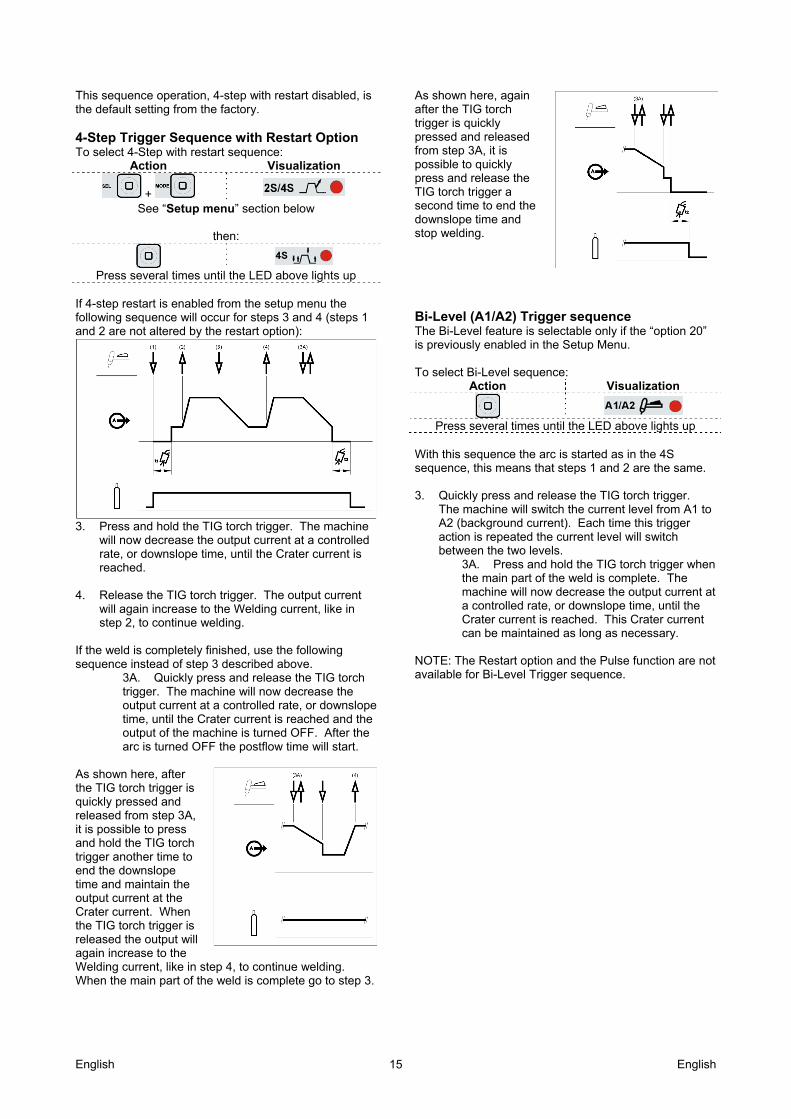
This sequence operation, 4-step with restart disabled, is the default setting from the factory. 4-Step Trigger Sequence with Restart Option To select 4-Step with restart sequence:
Action Visualization
+
See “Setup menu” section below
then:
Press several times until the LED above lights up
If 4-step restart is enabled from the setup menu the following sequence will occur for steps 3 and 4 (steps 1 and 2 are not altered by the restart option):
3. Press and hold the TIG torch trigger. The machine
will now decrease the output current at a controlled rate, or downslope time, until the Crater current is reached.
4. Release the TIG torch trigger. The output current
will again increase to the Welding current, like in step 2, to continue welding.
If the weld is completely finished, use the following sequence instead of step 3 described above.
3A. Quickly press and release the TIG torch trigger. The machine will now decrease the output current at a controlled rate, or downslope time, until the Crater current is reached and the output of the machine is turned OFF. After the arc is turned OFF the postflow time will start.
As shown here, after the TIG torch trigger is quickly pressed and released from step 3A, it is possible to press and hold the TIG torch trigger another time to end the downslope time and maintain the output current at the Crater current. When the TIG torch trigger is released the output will again increase to the Welding current, like in step 4, to continue welding. When the main part of the weld is complete go to step 3.
As shown here, again after the TIG torch trigger is quickly pressed and released from step 3A, it is possible to quickly press and release the TIG torch trigger a second time to end the downslope time and stop welding. Bi-Level (A1/A2) Trigger sequence The Bi-Level feature is selectable only if the “option 20” is previously enabled in the Setup Menu. To select Bi-Level sequence:
Action Visualization
Press several times until the LED above lights up
With this sequence the arc is started as in the 4S sequence, this means that steps 1 and 2 are the same.
3. Quickly press and release the TIG torch trigger.
The machine will switch the current level from A1 to A2 (background current). Each time this trigger action is repeated the current level will switch between the two levels.
3A. Press and hold the TIG torch trigger when the main part of the weld is complete. The machine will now decrease the output current at a controlled rate, or downslope time, until the Crater current is reached. This Crater current can be maintained as long as necessary.
NOTE: The Restart option and the Pulse function are not available for Bi-Level Trigger sequence.
English English 16
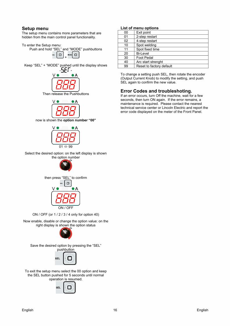
Setup menu The setup menu contains more parameters that are hidden from the main control panel functionality. To enter the Setup menu:
Push and hold “SEL” and “MODE” pushbuttons
+
Keep “SEL” + “MODE” pushed until the display shows
“ ”
Then release the Pushbuttons
now is shown the option number “00”
01 99
Select the desired option: on the left display is shown the option number
then press “SEL” to confirm
ON / OFF
ON / OFF (or 1 / 2 / 3 / 4 only for option 40)
Now enable, disable or change the option value: on the right display is shown the option status
Save the desired option by pressing the “SEL” pushbutton
To exit the setup menu select the 00 option and keep the SEL button pushed for 5 seconds until normal
operation is resumed.
List of menu options
00 Exit point 01 2-step restart 02 4-step restart 10 Spot welding 11 Spot fixed time 20 Bi-Level 30 Foot Pedal 40 Arc start strenght 99 Reset to factory default
To change a setting push SEL, then rotate the encoder (Output Current Knob) to modify the setting, and push SEL again to confirm the new value.
Error Codes and troubleshoting. If an error occurs, turn Off the machine, wait for a few seconds, then turn ON again. If the error remains, a maintenance is required. Please contact the nearest technical service center or Lincoln Electric and report the error code displayed on the meter of the Front Panel.
English English 17
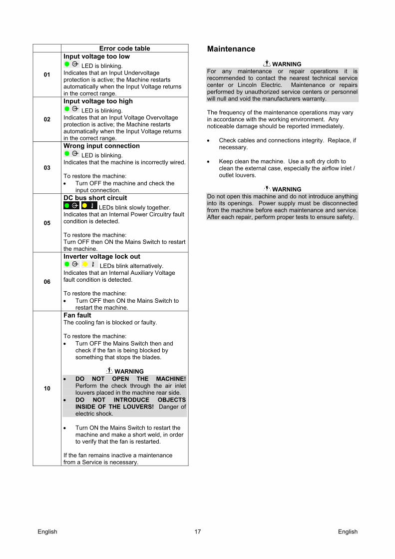
Error code table
01
Input voltage too low
LED is blinking. Indicates that an Input Undervoltage protection is active; the Machine restarts automatically when the Input Voltage returns in the correct range.
02
Input voltage too high
LED is blinking. Indicates that an Input Voltage Overvoltage protection is active; the Machine restarts automatically when the Input Voltage returns in the correct range.
03
Wrong input connection
LED is blinking. Indicates that the machine is incorrectly wired. To restore the machine: Turn OFF the machine and check the
input connection.
05
DC bus short circuit
LEDs blink slowly together. Indicates that an Internal Power Circuitry fault condition is detected. To restore the machine: Turn OFF then ON the Mains Switch to restart the machine.
06
Inverter voltage lock out
LEDs blink alternatively. Indicates that an Internal Auxiliary Voltage fault condition is detected. To restore the machine: Turn OFF then ON the Mains Switch to
restart the machine.
10
Fan fault The cooling fan is blocked or faulty. To restore the machine: Turn OFF the Mains Switch then and
check if the fan is being blocked by something that stops the blades.
WARNING
DO NOT OPEN THE MACHINE! Perform the check through the air inlet louvers placed in the machine rear side.
DO NOT INTRODUCE OBJECTS INSIDE OF THE LOUVERS! Danger of electric shock.
Turn ON the Mains Switch to restart the
machine and make a short weld, in order to verify that the fan is restarted.
If the fan remains inactive a maintenance from a Service is necessary.
Maintenance
WARNING For any maintenance or repair operations it is recommended to contact the nearest technical service center or Lincoln Electric. Maintenance or repairs performed by unauthorized service centers or personnel will null and void the manufacturers warranty. The frequency of the maintenance operations may vary in accordance with the working environment. Any noticeable damage should be reported immediately. Check cables and connections integrity. Replace, if
necessary. Keep clean the machine. Use a soft dry cloth to
clean the external case, especially the airflow inlet / outlet louvers.
WARNING
Do not open this machine and do not introduce anything into its openings. Power supply must be disconnected from the machine before each maintenance and service. After each repair, perform proper tests to ensure safety.
English English 18
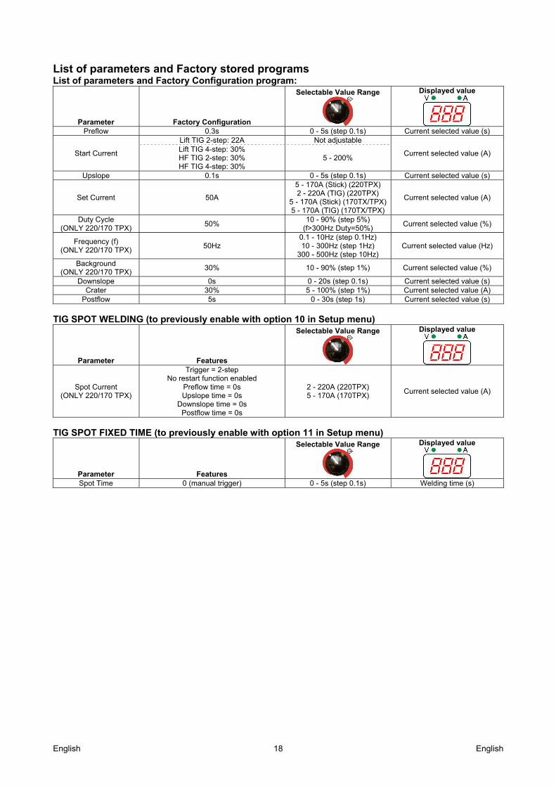
List of parameters and Factory stored programs List of parameters and Factory Configuration program:
Parameter Factory Configuration
Selectable Value Range Displayed value
Preflow 0.3s 0 - 5s (step 0.1s) Current selected value (s)
Start Current
Lift TIG 2-step: 22A Not adjustable
Current selected value (A) Lift TIG 4-step: 30% HF TIG 2-step: 30% HF TIG 4-step: 30%
5 - 200%
Upslope 0.1s 0 - 5s (step 0.1s) Current selected value (s)
Set Current 50A
5 - 170A (Stick) (220TPX) 2 - 220A (TIG) (220TPX)
5 - 170A (Stick) (170TX/TPX) 5 - 170A (TIG) (170TX/TPX)
Current selected value (A)
Duty Cycle (ONLY 220/170 TPX)
50% 10 - 90% (step 5%)
(f>300Hz Duty=50%) Current selected value (%)
Frequency (f) (ONLY 220/170 TPX)
50Hz 0.1 - 10Hz (step 0.1Hz) 10 - 300Hz (step 1Hz)
300 - 500Hz (step 10Hz) Current selected value (Hz)
Background (ONLY 220/170 TPX)
30% 10 - 90% (step 1%) Current selected value (%)
Downslope 0s 0 - 20s (step 0.1s) Current selected value (s) Crater 30% 5 - 100% (step 1%) Current selected value (A)
Postflow 5s 0 - 30s (step 1s) Current selected value (s) TIG SPOT WELDING (to previously enable with option 10 in Setup menu)
Parameter Features
Selectable Value Range Displayed value
Spot Current (ONLY 220/170 TPX)
Trigger = 2-step No restart function enabled
Preflow time = 0s Upslope time = 0s
Downslope time = 0s Postflow time = 0s
2 - 220A (220TPX) 5 - 170A (170TPX)
Current selected value (A)
TIG SPOT FIXED TIME (to previously enable with option 11 in Setup menu)
Parameter Features
Selectable Value Range Displayed value
Spot Time 0 (manual trigger) 0 - 5s (step 0.1s) Welding time (s)

English English 19
WEEE 07/06
En
gli
sh
Do not dispose of electrical equipment together with normal waste! In observance of European Directive 2012/19/EC on Waste Electrical and Electronic Equipment (WEEE) and its implementation in accordance with national law, electrical equipment that has reached the end of its life must be collected separately and returned to an environmentally compatible recycling facility. As the owner of the equipment, you should get information on approved collection systems from our local representative. By applying this European Directive you will protect the environment and human health!
Spare Parts 12/05
Part List reading instructions Do not use this part list for a machine if its code number is not listed. Contact the Lincoln Electric Service
Department for any code number not listed. Use the illustration of assembly page and the table below to determine where the part is located for your particular
code machine. Use only the parts marked "X" in the column under the heading number called for in the assembly page (# indicate
a change in this printing). First, read the Part List reading instructions above, then refer to the "Spare Part" manual supplied with the machine, that contains a picture-descriptive part number cross-reference.
Electrical Schematic Refer to the "Spare Part" manual supplied with the machine.
Suggested Accessories KIT-200A-25-3M Cable Kit 200A - 25 mm2 - 3m KIT-200A-35-5M Cable Kit 200A -35mm2 -5m KIT-250A-35-5M Cable Kit 250A -35mm2 -5m GRD-200A-35-xM Ground cable 200A -35mm2 -5/10m K10513-17-x TIG torch LT 17 G -140A -4/8m K10513-9-x TIG torch LT 9 G -110A -4/8m K10513-26-x TIG torch LT 26 G -180A -4/8m K14147-1 Remote control - 15 m K14148-1 Extension cord 15m (*) K870 Foot Amptrol.
(*) Only 2 Extension Cord for a maximum total length of 45m can be used.