
InventorCAM 2013 Milling Training Course 2 5D Milling
298
2.5D MILLING Training Course InventorCAM + Inventor The complete integrated Manufacturing Solution Autodesk Inventor 2013 Certified
Transcript of InventorCAM 2013 Milling Training Course 2 5D Milling
2.5D MILLINGTraining Course
InventorCAM + InventorThe complete integrated Manufacturing Solution
Autodesk® Inventor®
2013 Certi�ed

InventorCAM 2013
Milling Training Course
2.5D Milling
©1995-2012 SolidCAM
All Rights Reserved.

Contents
v
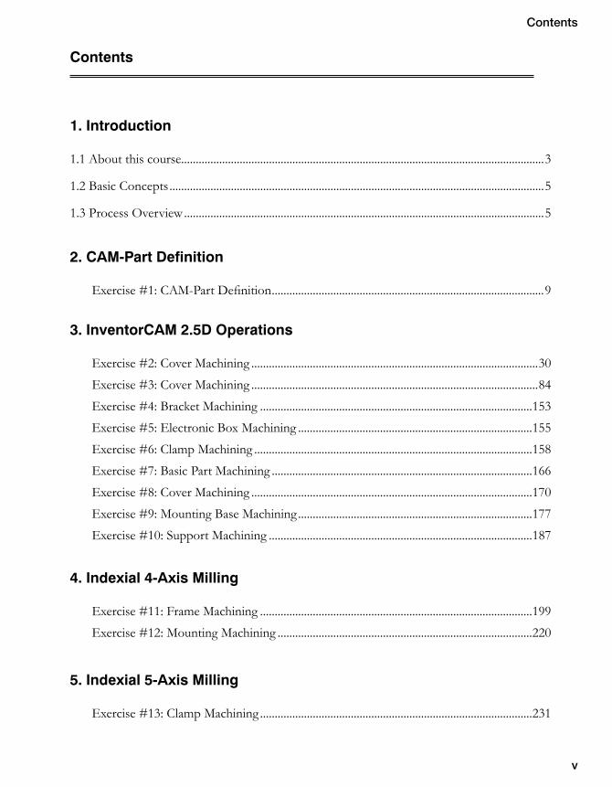
Contents
1. Introduction
1.1 About this course ............................................................................................................................3
1.2 Basic Concepts ................................................................................................................................5
1.3 Process Overview ...........................................................................................................................5
2. CAM-Part Definition
Exercise #1: CAM-Part Definition .............................................................................................9
3. InventorCAM 2.5D Operations
Exercise #2: Cover Machining ..................................................................................................30
Exercise #3: Cover Machining ..................................................................................................84
Exercise #4: Bracket Machining .............................................................................................153
Exercise #5: Electronic Box Machining ................................................................................155
Exercise #6: Clamp Machining ...............................................................................................158
Exercise #7: Basic Part Machining .........................................................................................166
Exercise #8: Cover Machining ................................................................................................170
Exercise #9: Mounting Base Machining ................................................................................177
Exercise #10: Support Machining ..........................................................................................187
4. Indexial 4-Axis Milling
Exercise #11: Frame Machining .............................................................................................199
Exercise #12: Mounting Machining .......................................................................................220
5. Indexial 5-Axis Milling
Exercise #13: Clamp Machining .............................................................................................231

vi
6. ToolBox
Exercise #14: Standard Cycles Machining .............................................................................240
7. Automatic Feature Recognition
Exercise #15: Pocket Recognition ..........................................................................................255
Exercise #16: Mounting Box Machining ...............................................................................262
Exercise #17: Drill Recognition ..............................................................................................264
Exercise #18: Electronic Box Machining ..............................................................................289
Document number: ICMTCENG12001

Introduction 1

2
3
1. Introduction
1.1 About this course
The goal of this course is to teach you how to use InventorCAM to machine various parts using 2.5D Milling technologies. This course covers the basic concepts of InventorCAM 2.5D machining and is a supplement to the system documentation and online help. Once you have developed a good foundation in basic skills, you can refer to the online help for information on the less frequently used options.
Course design
This course is designed around a task-based approach to training. With the guided exercises you will learn the commands and options necessary to complete a machining task. The theoretical explanations are embedded into these exercises to give an overview of the InventorCAM 2.5D Milling capabilities.
Using this training book
This training book is intended to be used both in a classroom environment under the guidance of an experienced instructor and as self-study material. It contains a number of laboratory exercises to enable you to apply and practice the material covered by the guided exercises. The laboratory exercises do not contain step-by-step instructions.
About the CD
The CD supplied together with this book contains copies of various files that are used throughout this course. The Exercises folder contains the files that are required for guided and laboratory exercises. The Built Parts folder inside the Exercises contains the final manufacturing projects for each exercise. Copy the complete Exercises folder on your computer. The Autodesk Inventor files used for the exercises were prepared with Autodesk Inventor 2013.
Windows 7
The screenshots in this book were made using InventorCAM 2013 integrated with Autodesk Inventor 2013 running on Windows 7. If you are running on a different version of Windows, you may notice differences in the appearance of menus and windows. These differences do not affect the performance of the software.
4
Conventions used in this book
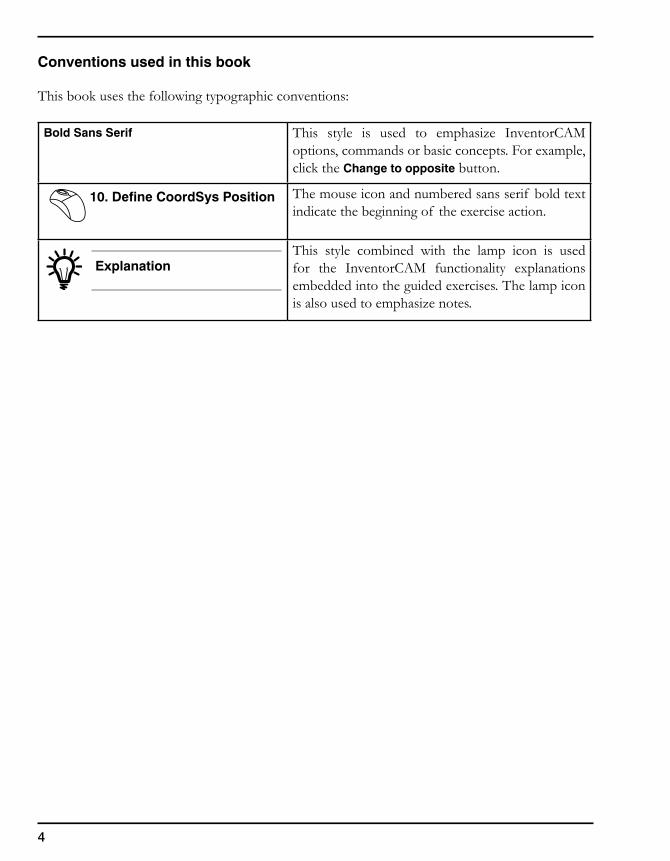
This book uses the following typographic conventions:
Bold Sans Serif This style is used to emphasize InventorCAM options, commands or basic concepts. For example, click the Change to opposite button.
10. Define CoordSys Position The mouse icon and numbered sans serif bold text indicate the beginning of the exercise action.
ExplanationThis style combined with the lamp icon is used for the InventorCAM functionality explanations embedded into the guided exercises. The lamp icon is also used to emphasize notes.
5
1. Introduction
1.2 Basic Concepts
Every manufacturing project in InventorCAM contains the following data:
• CAM-Part – The CAM-Part defines the general data of the workpiece. This includes the model name, the coordinate system position, tool options, CNC-controller, etc.
• Geometry – By selecting Edges, Curves, Surfaces or Solids, define what and where you are going to machine. This geometry is associated with the native Autodesk Inventor model.
• Operation – An Operation is a single machining step in InventorCAM. Technology, Tool parameters and Strategies are defined in the Operation. In short, Operation means how you want to machine.
1.3 Process Overview
The major stages of the InventorCAM manufacturing project creation process are the following:
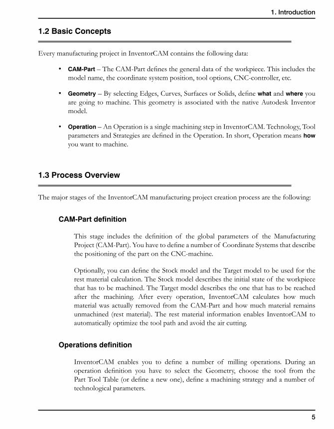
CAM-Part definition
This stage includes the definition of the global parameters of the Manufacturing Project (CAM-Part). You have to define a number of Coordinate Systems that describe the positioning of the part on the CNC-machine.
Optionally, you can define the Stock model and the Target model to be used for the rest material calculation. The Stock model describes the initial state of the workpiece that has to be machined. The Target model describes the one that has to be reached after the machining. After every operation, InventorCAM calculates how much material was actually removed from the CAM-Part and how much material remains unmachined (rest material). The rest material information enables InventorCAM to automatically optimize the tool path and avoid the air cutting.
Operations definition
InventorCAM enables you to define a number of milling operations. During an operation definition you have to select the Geometry, choose the tool from the Part Tool Table (or define a new one), define a machining strategy and a number of technological parameters.

6

CAM-PartDefinition 2
8
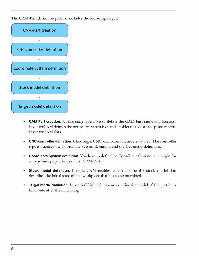
The CAM-Part definition process includes the following stages:
• CAM-Part creation. At this stage, you have to define the CAM-Part name and location. InventorCAM defines the necessary system files and a folder to allocate the place to store InventorCAM data.
• CNC-controller definition. Choosing a CNC-controller is a necessary step. The controller type influences the Coordinate System definition and the Geometry definition.
• Coordinate System definition. You have to define the Coordinate System – the origin for all machining operations of the CAM-Part.
• Stock model definition. InventorCAM enables you to define the stock model that describes the initial state of the workpiece that has to be machined.
• Target model definition. InventorCAM enables you to define the model of the part in its final state after the machining.
CAM-Part creation
Coordinate System definition
Stock model definition
CNC-controller definition
Target model definition
9
2. CAM-Part Definition
Exercise #1: CAM-Part Definition
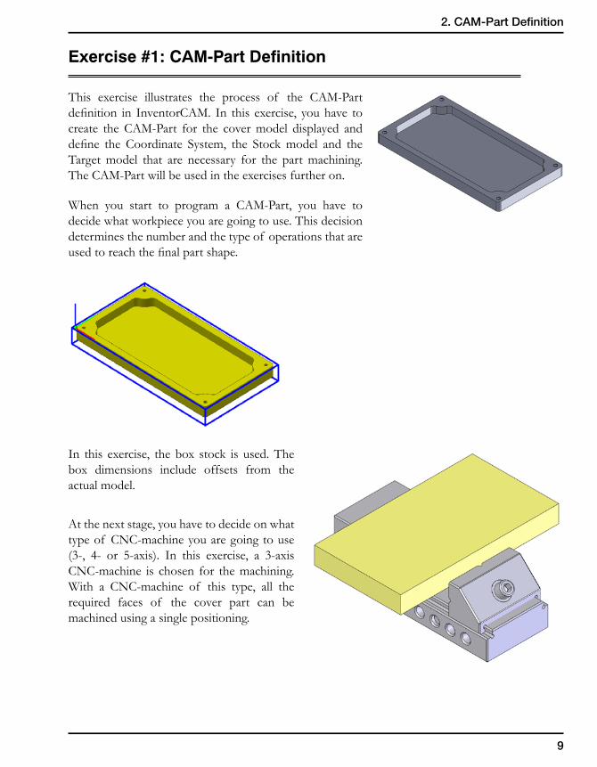
This exercise illustrates the process of the CAM-Part definition in InventorCAM. In this exercise, you have to create the CAM-Part for the cover model displayed and define the Coordinate System, the Stock model and the Target model that are necessary for the part machining. The CAM-Part will be used in the exercises further on.
When you start to program a CAM-Part, you have to decide what workpiece you are going to use. This decision determines the number and the type of operations that are used to reach the final part shape.
In this exercise, the box stock is used. The box dimensions include offsets from the actual model.
At the next stage, you have to decide on what type of CNC-machine you are going to use (3-, 4- or 5-axis). In this exercise, a 3-axis CNC-machine is chosen for the machining. With a CNC-machine of this type, all the required faces of the cover part can be machined using a single positioning.
10
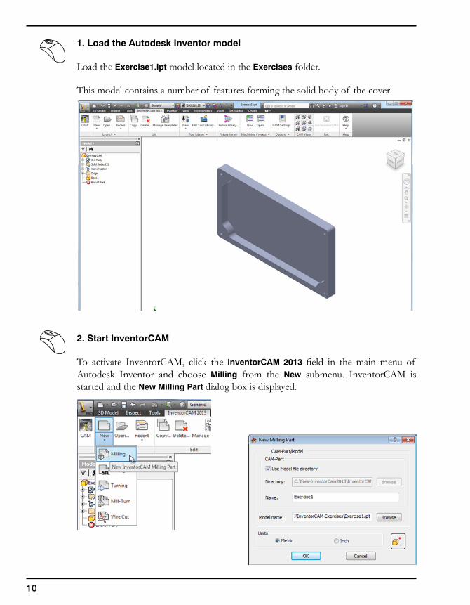
1. Load the Autodesk Inventor model
Load the Exercise1.ipt model located in the Exercises folder.
This model contains a number of features forming the solid body of the cover.
2. Start InventorCAM
To activate InventorCAM, click the InventorCAM 2013 field in the main menu of Autodesk Inventor and choose Milling from the New submenu. InventorCAM is started and the New Milling Part dialog box is displayed.
11
2. CAM-Part Definition
New Milling Part dialog box
When you create a new CAM-Part, you have to enter a name for the CAM-Part and for the model that contains the CAM-Part geometry.
Directory
Specify the location of the CAM-Part. The default directory is the InventorCAM user directory (defined in the InventorCAM Settings). You can enter the path or use the Browse button to define the location.
The Use Model file directory option enables you to automatically create CAM-Parts in the same folder where the original CAD model is located.
CAM-Part name
Enter a name for the CAM-Part. You can give any name to identify your machining project. By default, InventorCAM uses the name of the design model.
Model name
This field shows the name and location of the Autodesk Inventor design model that you are using for the CAM-Part definition. The name is, by default, the name of the active Autodesk Inventor document. With the Browse button you can choose any other Autodesk Inventor document to define the CAM-Part. In this case, the chosen Autodesk Inventor document is loaded into Autodesk Inventor.
Every time the CAM-Part is opened, InventorCAM automatically checks the correspondence of the dates of the CAM-Part and the original Autodesk Inventor design model. When the date of the original Autodesk Inventor model is later than the date of the CAM-Part creation, this means that the Autodesk Inventor original model has been updated. You can then replace the Autodesk Inventor design model on which the CAM-Part is based with the updated Autodesk Inventor design model.
12
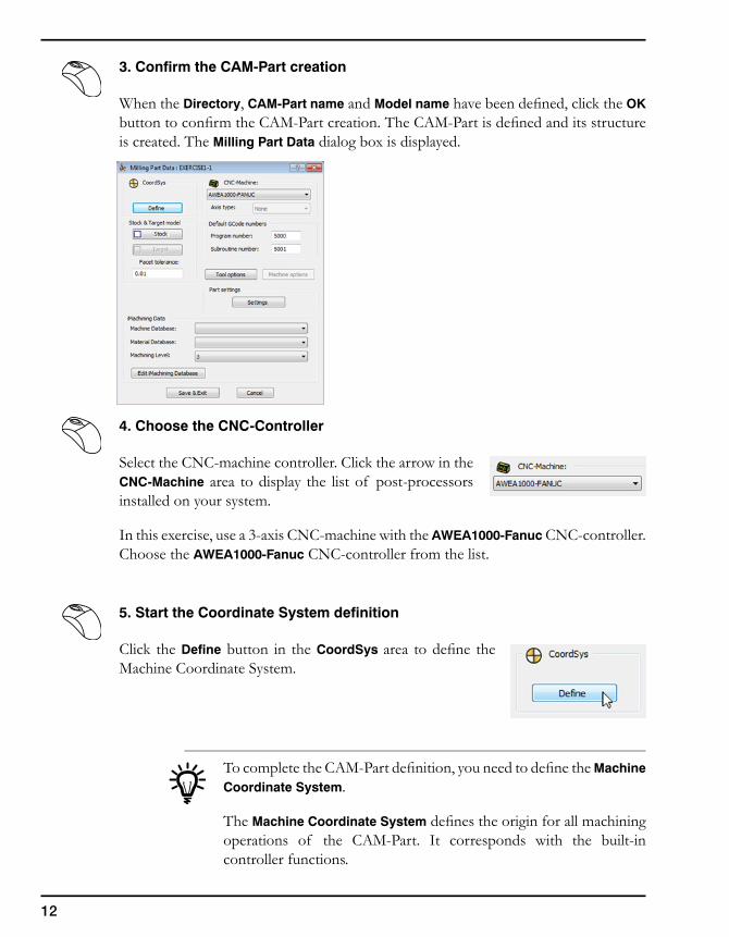
3. Confirm the CAM-Part creation
When the Directory, CAM-Part name and Model name have been defined, click the OK button to confirm the CAM-Part creation. The CAM-Part is defined and its structure is created. The Milling Part Data dialog box is displayed.
4. Choose the CNC-Controller
Select the CNC-machine controller. Click the arrow in the CNC-Machine area to display the list of post-processors installed on your system.
In this exercise, use a 3-axis CNC-machine with the AWEA1000-Fanuc CNC-controller. Choose the AWEA1000-Fanuc CNC-controller from the list.
5. Start the Coordinate System definition
Click the Define button in the CoordSys area to define the Machine Coordinate System.
To complete the CAM-Part definition, you need to define the Machine Coordinate System.
The Machine Coordinate System defines the origin for all machining operations of the CAM-Part. It corresponds with the built-in controller functions.
13
2. CAM-Part Definition
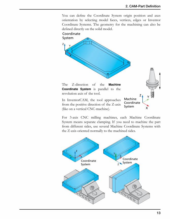
You can define the Coordinate System origin position and axes orientation by selecting model faces, vertices, edges or Inventor Coordinate Systems. The geometry for the machining can also be defined directly on the solid model.
The Z-direction of the Machine Coordinate System is parallel to the revolution axis of the tool.
In InventorCAM, the tool approaches from the positive direction of the Z-axis (like on a vertical CNC-machine).
For 3-axis CNC milling machines, each Machine Coordinate System means separate clamping. If you need to machine the part from different sides, use several Machine Coordinate Systems with the Z-axis oriented normally to the machined sides.
X
Z YMachineCoordinate System
X
ZY
CoordinateSystem
X
Z
Y
X
Z
YCoordinateSystem
CoordinateSystem
14
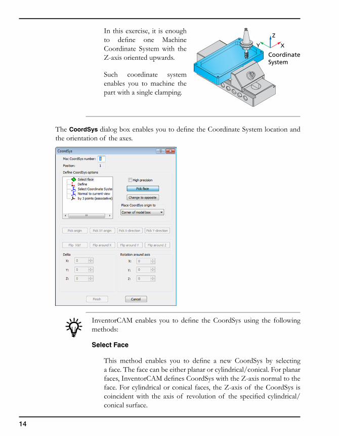
In this exercise, it is enough to define one Machine Coordinate System with the Z-axis oriented upwards.
Such coordinate system enables you to machine the part with a single clamping.
The CoordSys dialog box enables you to define the Coordinate System location and the orientation of the axes.
InventorCAM enables you to define the CoordSys using the following methods:
Select Face
This method enables you to define a new CoordSys by selecting a face. The face can be either planar or cylindrical/conical. For planar faces, InventorCAM defines CoordSys with the Z-axis normal to the face. For cylindrical or conical faces, the Z-axis of the CoordSys is coincident with the axis of revolution of the specified cylindrical/conical surface.
X
Z
Y
CoordinateSystem
15
2. CAM-Part Definition
Define
This method enables you to define the Coordinate System by selecting points. You have to define the origin and the direction of the X- and the Y-axes.
Select Coordinate System
This method enables you to choose the Autodesk Inventor Coordinate System defined in the design model file as the CoordSys. The CoordSys origin and axes orientation are the same as those of the original Autodesk Inventor Coordinate System.
Normal to current view
This option enables you to define the Coordinate System with the Z-axis normal to the model view you are facing on your screen. The CoordSys origin will lie in the origin of the Autodesk Inventor Coordinate System, and the Z-axis will be directed normally to the chosen view of the model.
By 3 Points (Associative)
This option enables you to define the Coordinate System by selecting any 3 points.
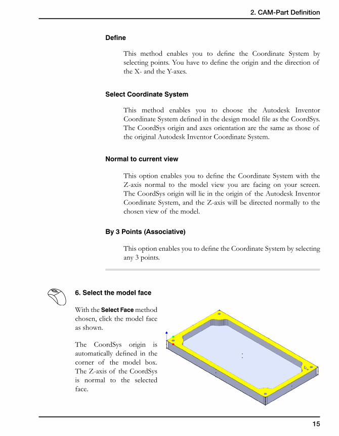
6. Select the model face
With the Select Face method chosen, click the model face as shown.
The CoordSys origin is automatically defined in the corner of the model box. The Z-axis of the CoordSys is normal to the selected face.
16
CoordinateSystem
X
Z Y
Model box
InventorCAM calculates the box surrounding the model. The upper plane of the model box is parallel to the XY-plane of the defined CoordSys.
The CoordSys is located in the corner of the model box.
Confirm by clicking the Finish button. The Coordinate System is defined.
The CoordSys Data dialog box is displayed.
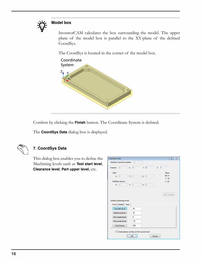
7. CoordSys Data
This dialog box enables you to define the Machining levels such as Tool start level, Clearance level, Part upper level, etc.
17
2. CAM-Part Definition
CoordSys Data dialog box
The Position field defines the sequential number of the CoordSys. For each Machine Coordinate System, several Position values are defined for different positions; each such Position value is related to the Machine CoordSys.
• X shows the X value of the CoordSys.
• Y shows the Y value of the CoordSys.
• Z shows the Z value of the CoordSys.
The Machine CoordSys number defines the number of the CoordSys in the CNC-machine. The default value is 1. If you use another number, the GCode file contains the G-function that prompts the machine to use the specified number stored in the machine controller of your machine.
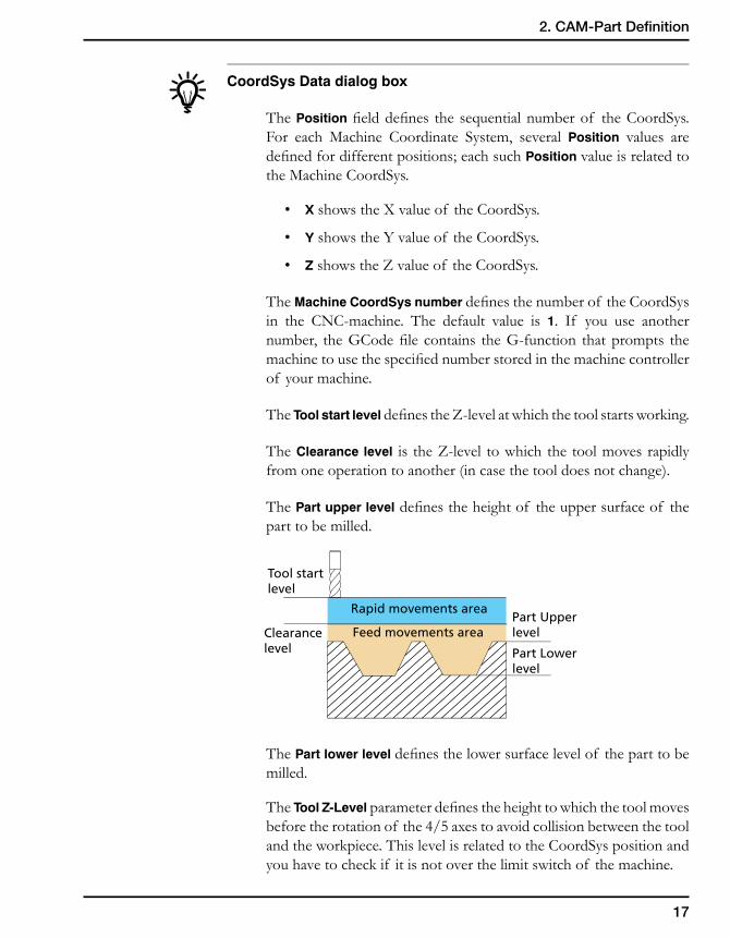
The Tool start level defines the Z-level at which the tool starts working.
The Clearance level is the Z-level to which the tool moves rapidly from one operation to another (in case the tool does not change).
The Part upper level defines the height of the upper surface of the part to be milled.
The Part lower level defines the lower surface level of the part to be milled.
The Tool Z-Level parameter defines the height to which the tool moves before the rotation of the 4/5 axes to avoid collision between the tool and the workpiece. This level is related to the CoordSys position and you have to check if it is not over the limit switch of the machine.
Rapid movements area
Feed movements areaPart Upperlevel
Part Lowerlevel
Tool startlevel
Clearancelevel
18
It is highly recommended to send the tool to the reference point or to a point related to the reference point.
The Create planar surface at Part Lower level option enables you to generate a transparent planar surface at the minimal Z-level of the part so that its lower level plane is visible. This planar surface provides you the possibility to select points that do not lie on the model entities. It is suppressed by default and not visible until you unsuppress it in the Model elements tree.
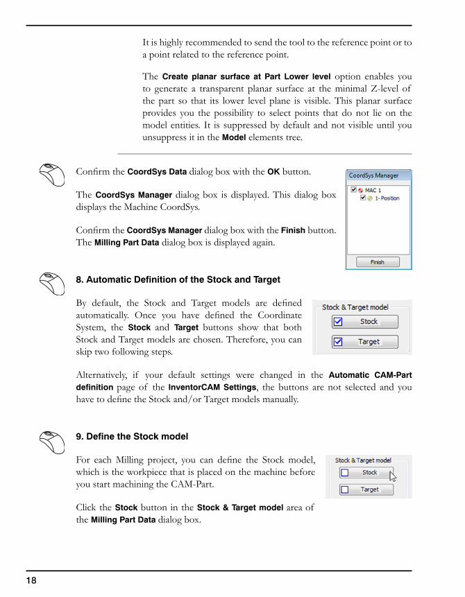
Confirm the CoordSys Data dialog box with the OK button.
The CoordSys Manager dialog box is displayed. This dialog box displays the Machine CoordSys.
Confirm the CoordSys Manager dialog box with the Finish button. The Milling Part Data dialog box is displayed again.
8. Automatic Definition of the Stock and Target
By default, the Stock and Target models are defined automatically. Once you have defined the Coordinate System, the Stock and Target buttons show that both Stock and Target models are chosen. Therefore, you can skip two following steps.
Alternatively, if your default settings were changed in the Automatic CAM-Part definition page of the InventorCAM Settings, the buttons are not selected and you have to define the Stock and/or Target models manually.
9. Define the Stock model
For each Milling project, you can define the Stock model, which is the workpiece that is placed on the machine before you start machining the CAM-Part.
Click the Stock button in the Stock & Target model area of the Milling Part Data dialog box.
19
2. CAM-Part Definition
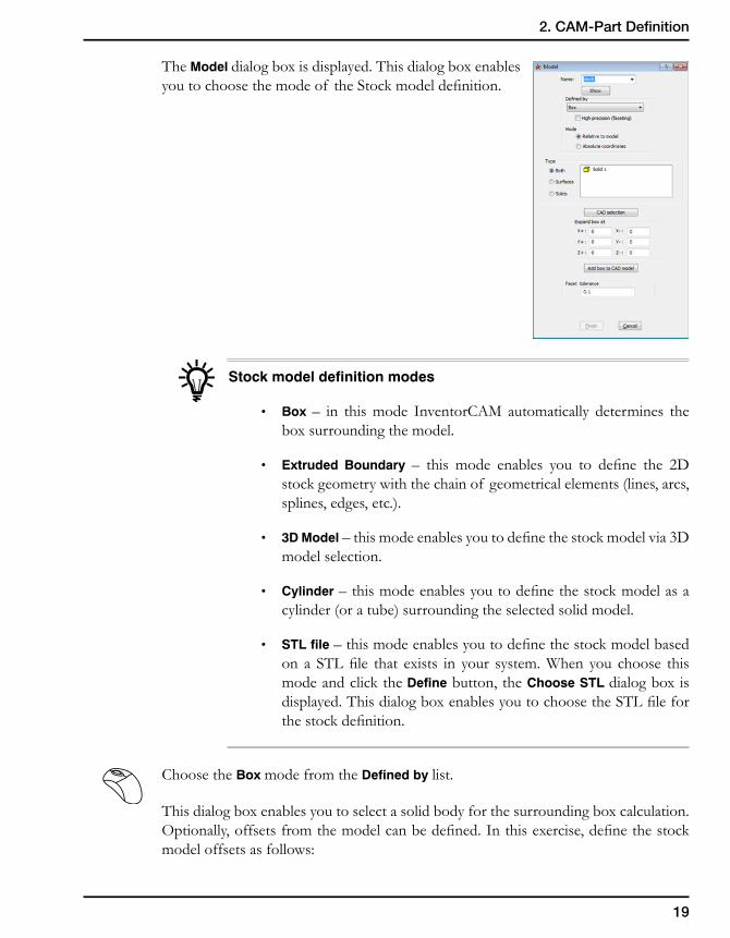
The Model dialog box is displayed. This dialog box enables you to choose the mode of the Stock model definition.
Stock model definition modes
• Box – in this mode InventorCAM automatically determines the box surrounding the model.
• Extruded Boundary – this mode enables you to define the 2D stock geometry with the chain of geometrical elements (lines, arcs, splines, edges, etc.).
• 3DModel – this mode enables you to define the stock model via 3D model selection.
• Cylinder– this mode enables you to define the stock model as a cylinder (or a tube) surrounding the selected solid model.
• STL file – this mode enables you to define the stock model based on a STL file that exists in your system. When you choose this mode and click the Define button, the Choose STL dialog box is displayed. This dialog box enables you to choose the STL file for the stock definition.
Choose the Box mode from the Defined by list.
This dialog box enables you to select a solid body for the surrounding box calculation. Optionally, offsets from the model can be defined. In this exercise, define the stock model offsets as follows:
20
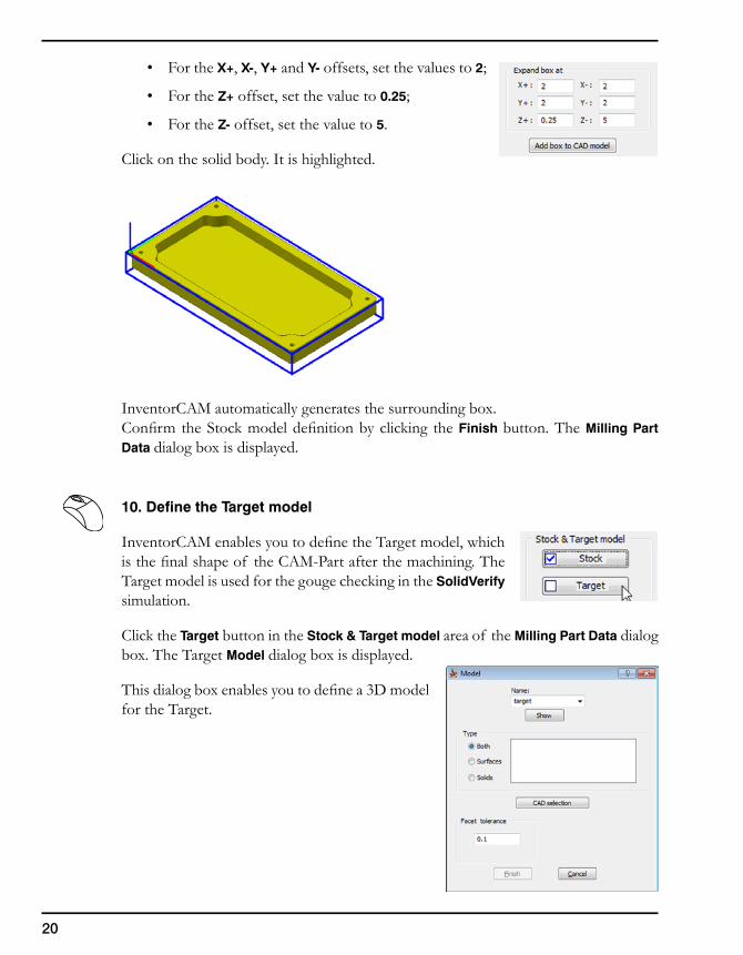
• For the X+, X-, Y+ and Y- offsets, set the values to 2;
• For the Z+ offset, set the value to 0.25;
• For the Z- offset, set the value to 5.
Click on the solid body. It is highlighted.
InventorCAM automatically generates the surrounding box.Confirm the Stock model definition by clicking the Finish button. The Milling Part Data dialog box is displayed.
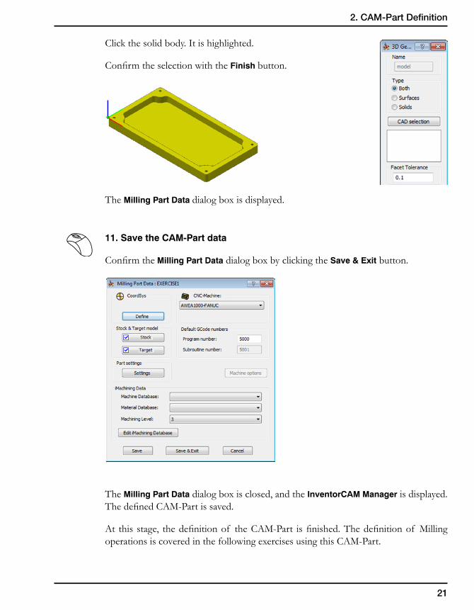
10. Define the Target model
InventorCAM enables you to define the Target model, which is the final shape of the CAM-Part after the machining. The Target model is used for the gouge checking in the SolidVerify simulation.
Click the Target button in the Stock & Target model area of the Milling Part Data dialog box. The Target Model dialog box is displayed.
This dialog box enables you to define a 3D model for the Target.
21
2. CAM-Part Definition
Click the solid body. It is highlighted.
Confirm the selection with the Finish button.
The Milling Part Data dialog box is displayed.
11. Save the CAM-Part data
Confirm the Milling Part Data dialog box by clicking the Save & Exit button.
The Milling Part Data dialog box is closed, and the InventorCAM Manager is displayed. The defined CAM-Part is saved.
At this stage, the definition of the CAM-Part is finished. The definition of Milling operations is covered in the following exercises using this CAM-Part.
22
The structure of the CAM-Part
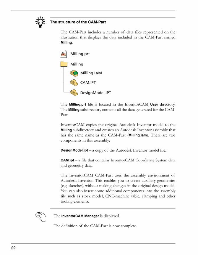
The CAM-Part includes a number of data files represented on the illustration that displays the data included in the CAM-Part named Milling.
The Milling.prt file is located in the InventorCAM User directory. The Milling subdirectory contains all the data generated for the CAM-Part.
InventorCAM copies the original Autodesk Inventor model to the Milling subdirectory and creates an Autodesk Inventor assembly that has the same name as the CAM-Part (Milling.iam). There are two components in this assembly:
DesignModel.ipt – a copy of the Autodesk Inventor model file.
CAM.ipt – a file that contains InventorCAM Coordinate System data and geometry data.
The InventorCAM CAM-Part uses the assembly environment of Autodesk Inventor. This enables you to create auxiliary geometries (e.g. sketches) without making changes in the original design model. You can also insert some additional components into the assembly file such as stock model, CNC-machine table, clamping and other tooling elements.
The InventorCAM Manager is displayed.
The definition of the CAM-Part is now complete.
Milling.prt
Milling.IAM
CAM.IPT
DesignModel.IPT
Milling
23
2. CAM-Part Definition
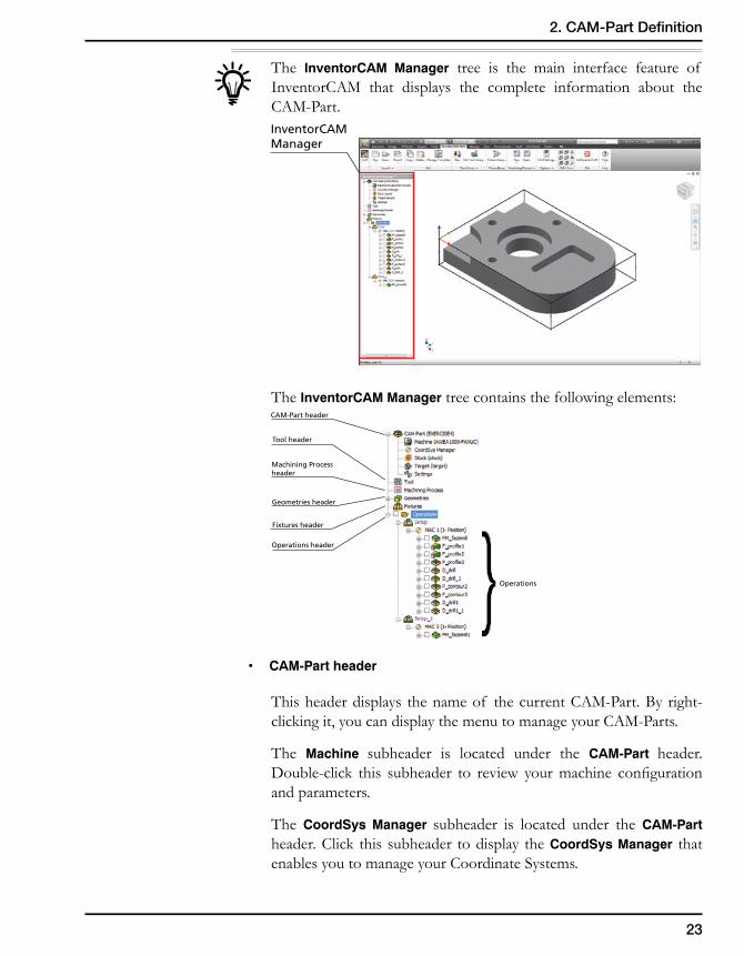
The InventorCAM Manager tree is the main interface feature of InventorCAM that displays the complete information about the CAM-Part.
The InventorCAM Manager tree contains the following elements:
• CAM-Partheader
This header displays the name of the current CAM-Part. By right-clicking it, you can display the menu to manage your CAM-Parts.
The Machine subheader is located under the CAM-Part header. Double-click this subheader to review your machine configuration and parameters.
The CoordSys Manager subheader is located under the CAM-Part header. Click this subheader to display the CoordSys Manager that enables you to manage your Coordinate Systems.
InventorCAMManager
CAM-Part header
Operations
Tool header
Machining Processheader
Geometries header
Operations header
Fixtures header
}
24
The Stock and Target subheaders are located under the CAM-Part header. Double-click these subheaders to load the Stock Model/Target Model dialog boxes that enable you to change the definition of the Stock/Target models.
The Settings subheader is also located under the CAM-Part header. Double-click this subheader to load the Part Settings dialog box that enables you to edit the settings defined for the current CAM-Part.
• Toolheader
This header displays the name of the current Tool Library. Double-click its icon to display the Part Tool Table, which is the list of the tools that are available to use in the current CAM-Part.
• MachiningProcessheader
This header displays the name of the current Machining Process table.
• Geometriesheader
This header displays all InventorCAM geometries that are not used in the operations.
• Operationsheader
This header shows you all InventorCAM operations defined for the current CAM-Part.
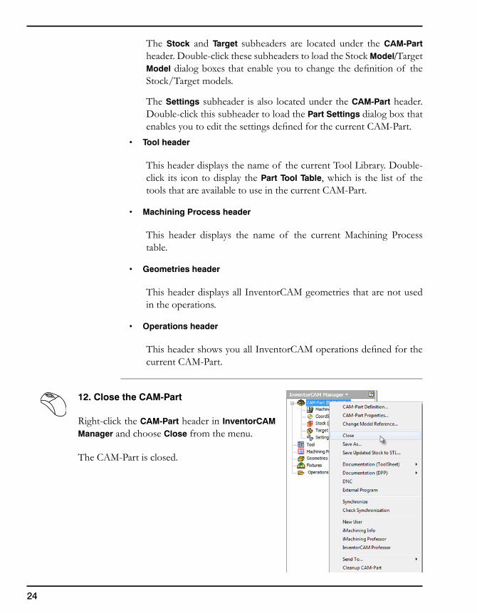
12. Close the CAM-Part
Right-click the CAM-Part header in InventorCAM Manager and choose Close from the menu.
The CAM-Part is closed.

InventorCAM 2.5DOperations 3
26
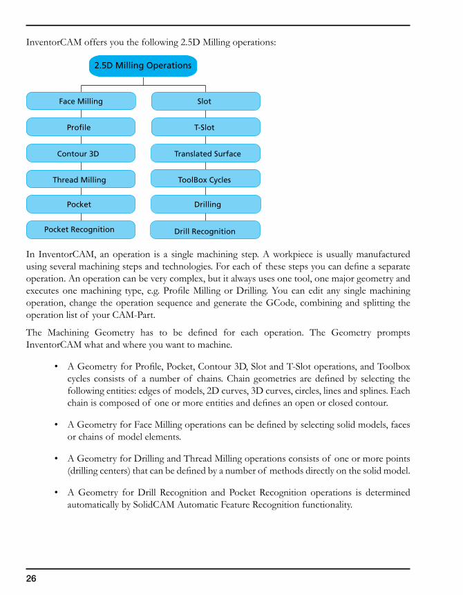
InventorCAM offers you the following 2.5D Milling operations:
In InventorCAM, an operation is a single machining step. A workpiece is usually manufactured using several machining steps and technologies. For each of these steps you can define a separate operation. An operation can be very complex, but it always uses one tool, one major geometry and executes one machining type, e.g. Profile Milling or Drilling. You can edit any single machining operation, change the operation sequence and generate the GCode, combining and splitting the operation list of your CAM-Part.
The Machining Geometry has to be defined for each operation. The Geometry prompts InventorCAM what and where you want to machine.
• A Geometry for Profile, Pocket, Contour 3D, Slot and T-Slot operations, and Toolbox cycles consists of a number of chains. Chain geometries are defined by selecting the following entities: edges of models, 2D curves, 3D curves, circles, lines and splines. Each chain is composed of one or more entities and defines an open or closed contour.
• A Geometry for Face Milling operations can be defined by selecting solid models, faces or chains of model elements.
• A Geometry for Drilling and Thread Milling operations consists of one or more points (drilling centers) that can be defined by a number of methods directly on the solid model.
• A Geometry for Drill Recognition and Pocket Recognition operations is determined automatically by SolidCAM Automatic Feature Recognition functionality.
2.5D Milling Operations
Slot
T-Slot
Pocket Drilling
Pocket Recognition
Face Milling
Thread Milling
Contour 3D
Profile
Translated Surface
ToolBox Cycles
Drill Recognition
27
3. InventorCAM 2.5D Operations
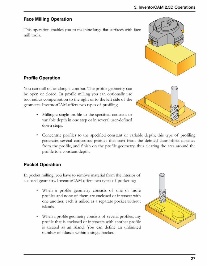
Face Milling Operation
This operation enables you to machine large flat surfaces with face mill tools.
Profile Operation
You can mill on or along a contour. The profile geometry can be open or closed. In profile milling you can optionally use tool radius compensation to the right or to the left side of the geometry. InventorCAM offers two types of profiling:
• Milling a single profile to the specified constant or variable depth in one step or in several user-defined down steps.
• Concentric profiles to the specified constant or variable depth; this type of profiling generates several concentric profiles that start from the defined clear offset distance from the profile, and finish on the profile geometry, thus clearing the area around the profile to a constant depth.
Pocket Operation
In pocket milling, you have to remove material from the interior of a closed geometry. InventorCAM offers two types of pocketing:
• When a profile geometry consists of one or more profiles and none of them are enclosed or intersect with one another, each is milled as a separate pocket without islands.
• When a profile geometry consists of several profiles, any profile that is enclosed or intersects with another profile is treated as an island. You can define an unlimited number of islands within a single pocket.
28
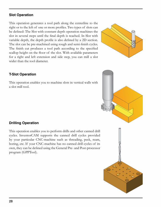
Slot Operation
This operation generates a tool path along the centerline to the right or to the left of one or more profiles. Two types of slots can be defined: The Slot with constant depth operation machines the slot in several steps until the final depth is reached. In Slot with variable depth, the depth profile is also defined by a 2D section. The slot can be pre-machined using rough and semi-finish cycles. The finish cut produces a tool path according to the specified scallop height on the floor of the slot. With available parameters for a right and left extension and side step, you can mill a slot wider than the tool diameter.
T-Slot Operation
This operation enables you to machine slots in vertical walls with a slot mill tool.
Drilling Operation
This operation enables you to perform drills and other canned drill cycles. InventorCAM supports the canned drill cycles provided by your particular CNC-machine such as threading, peck, ream, boring, etc. If your CNC-machine has no canned drill cycles of its own, they can be defined using the General Pre- and Post-processor program (GPPTool).
29
3. InventorCAM 2.5D Operations
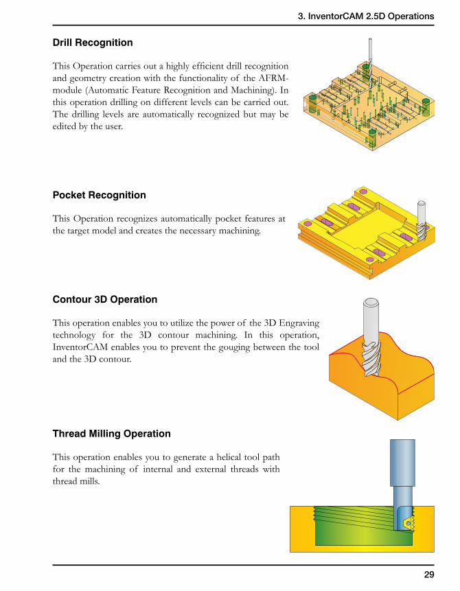
Drill Recognition
This Operation carries out a highly efficient drill recognition and geometry creation with the functionality of the AFRM-module (Automatic Feature Recognition and Machining). In this operation drilling on different levels can be carried out. The drilling levels are automatically recognized but may be edited by the user.
Pocket Recognition
This Operation recognizes automatically pocket features at the target model and creates the necessary machining.
Contour 3D Operation
This operation enables you to utilize the power of the 3D Engraving technology for the 3D contour machining. In this operation, InventorCAM enables you to prevent the gouging between the tool and the 3D contour.
Thread Milling Operation
This operation enables you to generate a helical tool path for the machining of internal and external threads with thread mills.
30
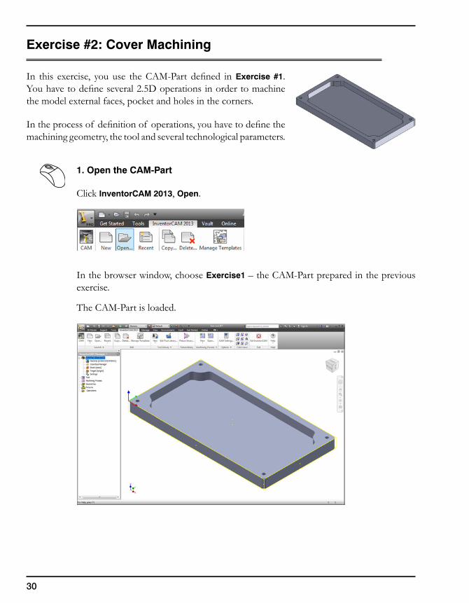
Exercise #2: Cover Machining
In this exercise, you use the CAM-Part defined in Exercise #1. You have to define several 2.5D operations in order to machine the model external faces, pocket and holes in the corners.
In the process of definition of operations, you have to define the machining geometry, the tool and several technological parameters.
1. Open the CAM-Part
Click InventorCAM 2013, Open.
In the browser window, choose Exercise1 – the CAM-Part prepared in the previous exercise.
The CAM-Part is loaded.
31
3. InventorCAM 2.5D Operations
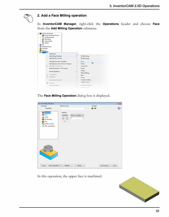
2. Add a Face Milling operation
In InventorCAM Manager, right-click the Operations header and choose Face from the Add Milling Operation submenu.
The Face Milling Operation dialog box is displayed.
In this operation, the upper face is machined.
32
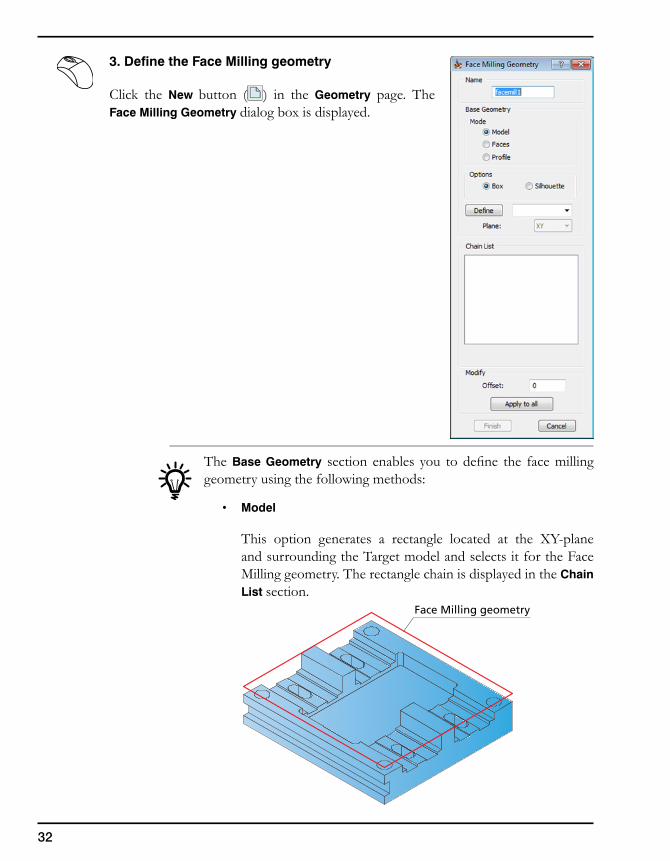
3. Define the Face Milling geometry
Click the New button ( ) in the Geometry page. The Face Milling Geometry dialog box is displayed.
The Base Geometry section enables you to define the face milling geometry using the following methods:
• Model
This option generates a rectangle located at the XY-plane and surrounding the Target model and selects it for the Face Milling geometry. The rectangle chain is displayed in the Chain List section.
Face Milling geometry
33
3. InventorCAM 2.5D Operations
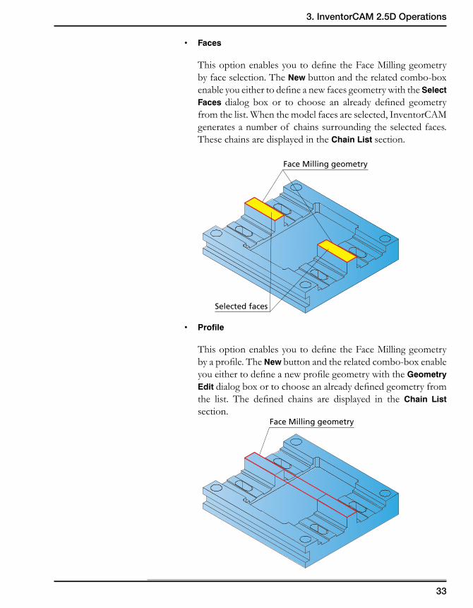
• Faces
This option enables you to define the Face Milling geometry by face selection. The New button and the related combo-box enable you either to define a new faces geometry with the Select Faces dialog box or to choose an already defined geometry from the list. When the model faces are selected, InventorCAM generates a number of chains surrounding the selected faces. These chains are displayed in the Chain List section.
• Profile
This option enables you to define the Face Milling geometry by a profile. The New button and the related combo-box enable you either to define a new profile geometry with the Geometry Edit dialog box or to choose an already defined geometry from the list. The defined chains are displayed in the Chain List section.
Face Milling geometry
Selected faces
Face Milling geometry
34
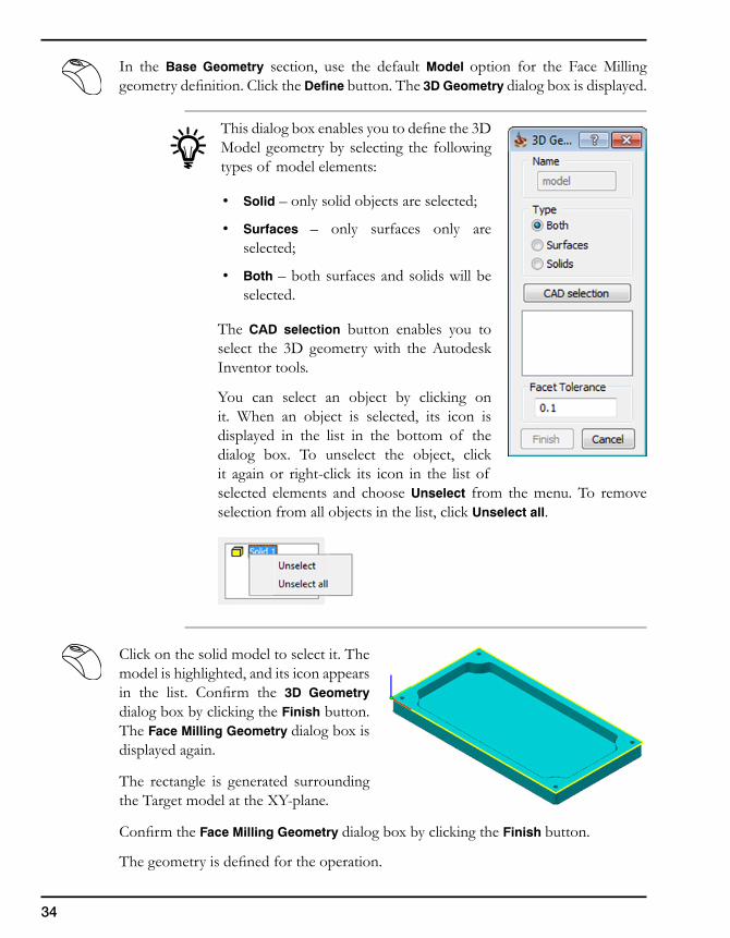
In the Base Geometry section, use the default Model option for the Face Milling geometry definition. Click the Define button. The 3D Geometry dialog box is displayed.
This dialog box enables you to define the 3D Model geometry by selecting the following types of model elements:
• Solid – only solid objects are selected;
• Surfaces – only surfaces only are selected;
• Both – both surfaces and solids will be selected.
The CAD selection button enables you to select the 3D geometry with the Autodesk Inventor tools.
You can select an object by clicking on it. When an object is selected, its icon is displayed in the list in the bottom of the dialog box. To unselect the object, click it again or right-click its icon in the list of selected elements and choose Unselect from the menu. To remove selection from all objects in the list, click Unselect all.
Click on the solid model to select it. The model is highlighted, and its icon appears in the list. Confirm the 3D Geometry dialog box by clicking the Finish button. The Face Milling Geometry dialog box is displayed again.
The rectangle is generated surrounding the Target model at the XY-plane.
Confirm the Face Milling Geometry dialog box by clicking the Finish button.
The geometry is defined for the operation.
35
3. InventorCAM 2.5D Operations
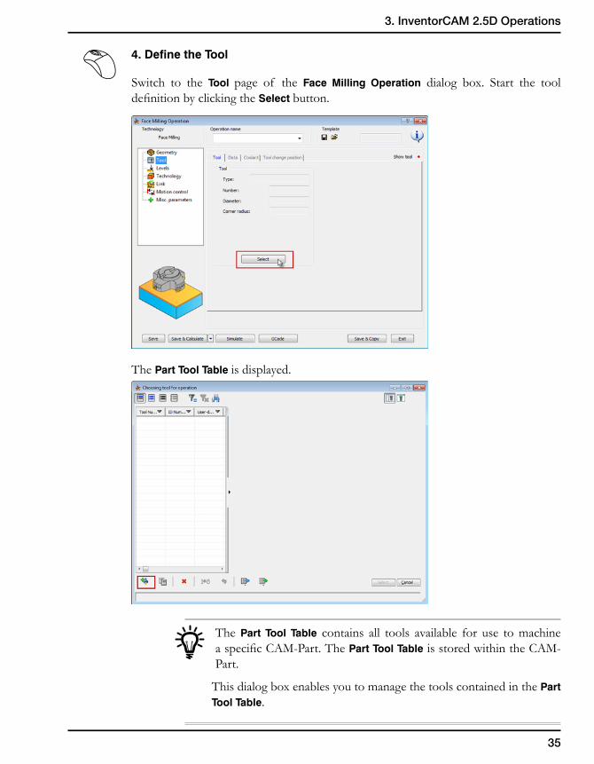
4. Define the Tool
Switch to the Tool page of the Face Milling Operation dialog box. Start the tool definition by clicking the Select button.
The Part Tool Table is displayed.
The Part Tool Table contains all tools available for use to machine a specific CAM-Part. The Part Tool Table is stored within the CAM-Part.
This dialog box enables you to manage the tools contained in the Part Tool Table.
36
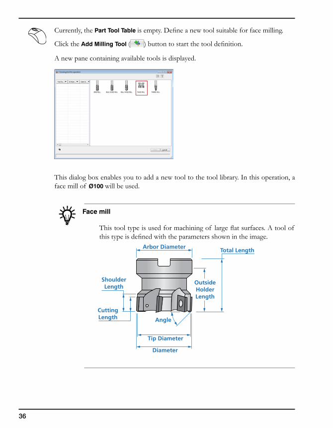
Currently, the Part Tool Table is empty. Define a new tool suitable for face milling.
Click the Add Milling Tool ( ) button to start the tool definition.
A new pane containing available tools is displayed.
This dialog box enables you to add a new tool to the tool library. In this operation, a face mill of Ø100 will be used.
Face mill
This tool type is used for machining of large flat surfaces. A tool of this type is defined with the parameters shown in the image.
OutsideHolderLength
CuttingLength
Arbor Diameter
Diameter
Tip Diameter
Total Length
ShoulderLength
Angle
37
3. InventorCAM 2.5D Operations
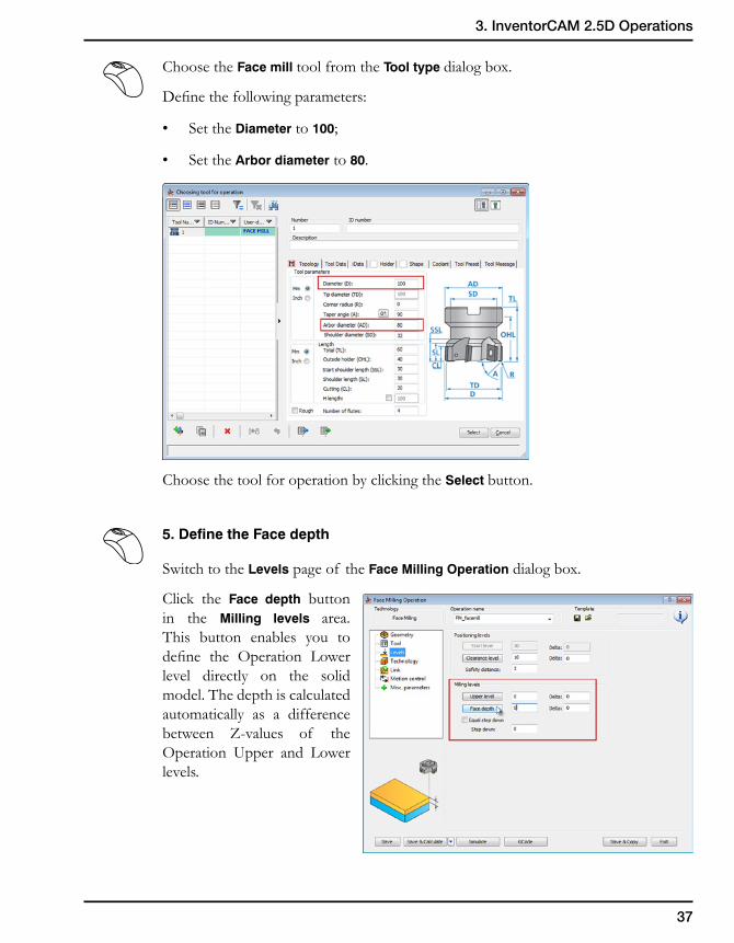
Choose the Face mill tool from the Tool type dialog box.
Define the following parameters:
• Set the Diameter to 100;
• Set the Arbor diameter to 80.
Choose the tool for operation by clicking the Select button.
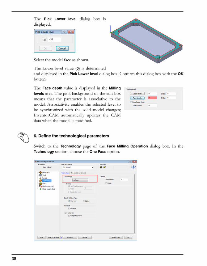
5. Define the Face depth
Switch to the Levels page of the Face Milling Operation dialog box.
Click the Face depth button in the Milling levels area. This button enables you to define the Operation Lower level directly on the solid model. The depth is calculated automatically as a difference between Z-values of the Operation Upper and Lower levels.
38
The Pick Lower level dialog box is displayed.
Select the model face as shown.
The Lower level value (0) is determined and displayed in the Pick Lower level dialog box. Confirm this dialog box with the OK button.
The Face depth value is displayed in the Milling levels area. The pink background of the edit box means that the parameter is associative to the model. Associativity enables the selected level to be synchronized with the solid model changes; InventorCAM automatically updates the CAM data when the model is modified.
6. Define the technological parameters
Switch to the Technology page of the Face Milling Operation dialog box. In the Technology section, choose the One Pass option.
39
3. InventorCAM 2.5D Operations
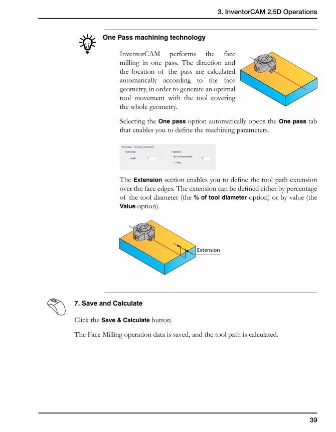
One Pass machining technology
InventorCAM performs the face milling in one pass. The direction and the location of the pass are calculated automatically according to the face geometry, in order to generate an optimal tool movement with the tool covering the whole geometry.
Selecting the One pass option automatically opens the One pass tab that enables you to define the machining parameters.
The Extension section enables you to define the tool path extension over the face edges. The extension can be defined either by percentage of the tool diameter (the % of tool diameter option) or by value (the Value option).
7. Save and Calculate
Click the Save & Calculate button.
The Face Milling operation data is saved, and the tool path is calculated.
Extension
40
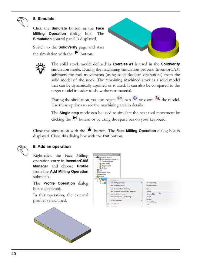
8. Simulate
Click the Simulate button in the Face Milling Operation dialog box. The Simulation control panel is displayed.
Switch to the SolidVerify page and start the simulation with the button.
The solid stock model defined in Exercise #1 is used in the SolidVerify simulation mode. During the machining simulation process, InventorCAM subtracts the tool movements (using solid Boolean operations) from the solid model of the stock. The remaining machined stock is a solid model that can be dynamically zoomed or rotated. It can also be compared to the target model in order to show the rest material.
During the simulation, you can rotate , pan or zoom the model. Use these options to see the machining area in details.
The Single step mode can be used to simulate the next tool movement by clicking the button or by using the space bar on your keyboard.
Close the simulation with the button. The Face Milling Operation dialog box is displayed. Close this dialog box with the Exit button.
9. Add an operation
Right-click the Face Milling operation entry in InventorCAM Manager and choose Profile from the Add Milling Operation submenu.The Profile Operation dialog box is displayed.In this operation, the external profile is machined.
41
3. InventorCAM 2.5D Operations
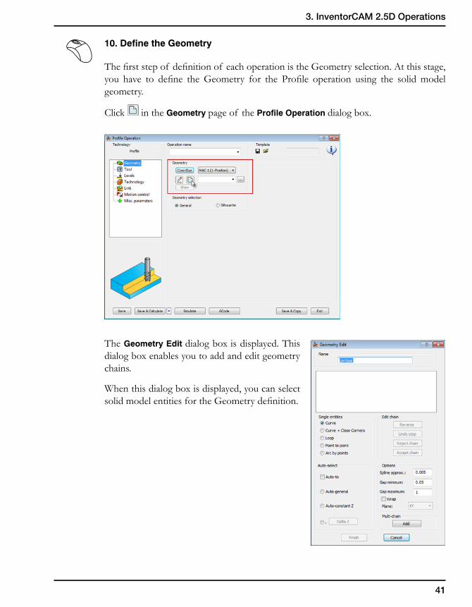
10. Define the Geometry
The first step of definition of each operation is the Geometry selection. At this stage, you have to define the Geometry for the Profile operation using the solid model geometry.
Click in the Geometry page of the Profile Operation dialog box.
The Geometry Edit dialog box is displayed. This dialog box enables you to add and edit geometry chains.
When this dialog box is displayed, you can select solid model entities for the Geometry definition.
42
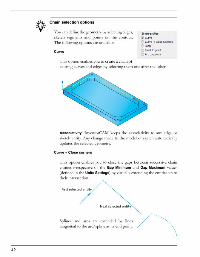
Chain selection options
You can define the geometry by selecting edges, sketch segments and points on the contour. The following options are available:
Curve
This option enables you to create a chain of existing curves and edges by selecting them one after the other.
Associativity: InventorCAM keeps the associativity to any edge or sketch entity. Any change made to the model or sketch automatically updates the selected geometry.
Curve + Close corners
This option enables you to close the gaps between successive chain entities irrespective of the Gap Minimum and Gap Maximum values (defined in the Units Settings) by virtually extending the entities up to their intersection.
Splines and arcs are extended by lines tangential to the arc/spline at its end point.
First selected entity
Next selected entity
43
3. InventorCAM 2.5D Operations
Associativity: When the model used for the geometry definition is modified, InventorCAM enables you to synchronize the geometry with the updated model. During the synchronization InventorCAM determines gaps areas created using the Curve + Close Corners option and regenerates the extension of the chain elements so as to close the gaps.
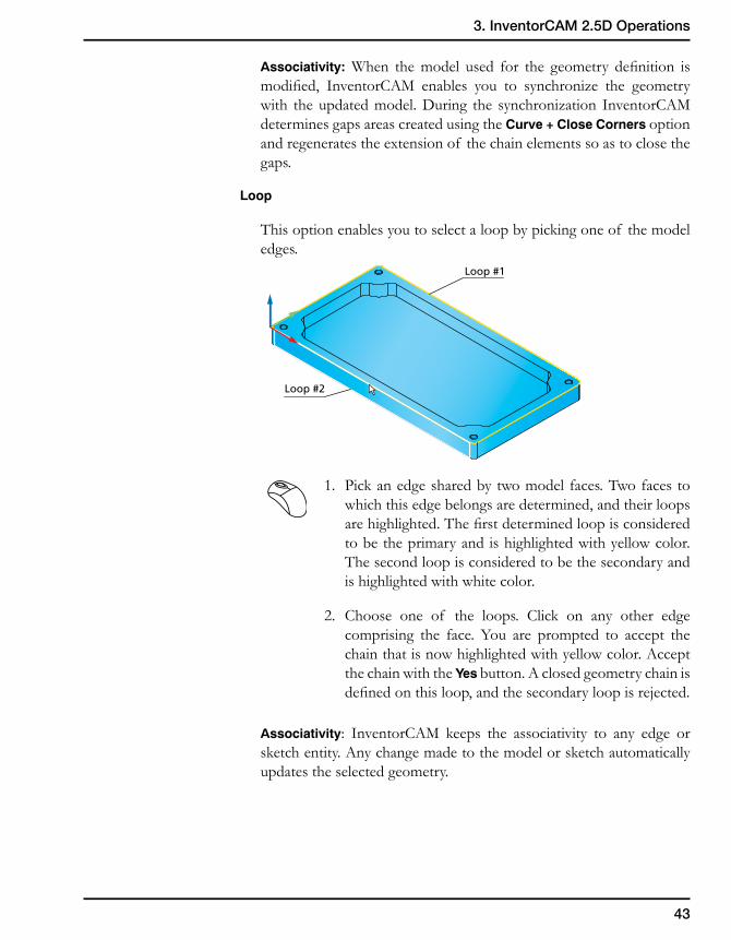
Loop
This option enables you to select a loop by picking one of the model edges.
1. Pick an edge shared by two model faces. Two faces to which this edge belongs are determined, and their loops are highlighted. The first determined loop is considered to be the primary and is highlighted with yellow color. The second loop is considered to be the secondary and is highlighted with white color.
2. Choose one of the loops. Click on any other edge comprising the face. You are prompted to accept the chain that is now highlighted with yellow color. Accept the chain with the Yes button. A closed geometry chain is defined on this loop, and the secondary loop is rejected.
Associativity: InventorCAM keeps the associativity to any edge or sketch entity. Any change made to the model or sketch automatically updates the selected geometry.
Loop #1
Loop #2
44
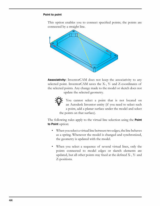
Point to point
This option enables you to connect specified points; the points are connected by a straight line.
Associativity: InventorCAM does not keep the associativity to any selected point. InventorCAM saves the X-, Y- and Z-coordinates of the selected points. Any change made to the model or sketch does not
update the selected geometry.
You cannot select a point that is not located on an Autodesk Inventor entity (if you need to select such a point, add a planar surface under the model and select
the points on that surface).
The following rules apply to the virtual line selection using the Point to Point option:
• When you select a virtual line between two edges, the line behaves as a spring. Whenever the model is changed and synchronized, the geometry is updated with the model.
• When you select a sequence of several virtual lines, only the points connected to model edges or sketch elements are updated, but all other points stay fixed at the defined X-, Y- and Z-positions.
45
3. InventorCAM 2.5D Operations
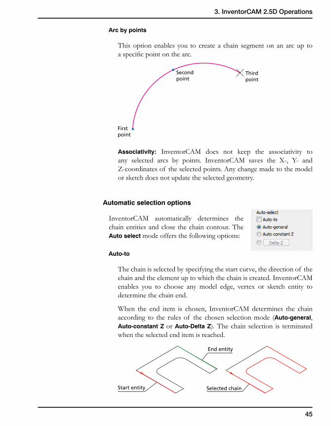
Arc by points
This option enables you to create a chain segment on an arc up to a specific point on the arc.
Associativity: InventorCAM does not keep the associativity to any selected arcs by points. InventorCAM saves the X-, Y- and Z-coordinates of the selected points. Any change made to the model or sketch does not update the selected geometry.
Automatic selection options
InventorCAM automatically determines the chain entities and close the chain contour. The Auto select mode offers the following options:
Auto-to
The chain is selected by specifying the start curve, the direction of the chain and the element up to which the chain is created. InventorCAM enables you to choose any model edge, vertex or sketch entity to determine the chain end.
When the end item is chosen, InventorCAM determines the chain according to the rules of the chosen selection mode (Auto-general, Auto-constant Z or Auto-Delta Z). The chain selection is terminated when the selected end item is reached.
First point
Second point
Third point
Start entity Selected chain
End entity
46
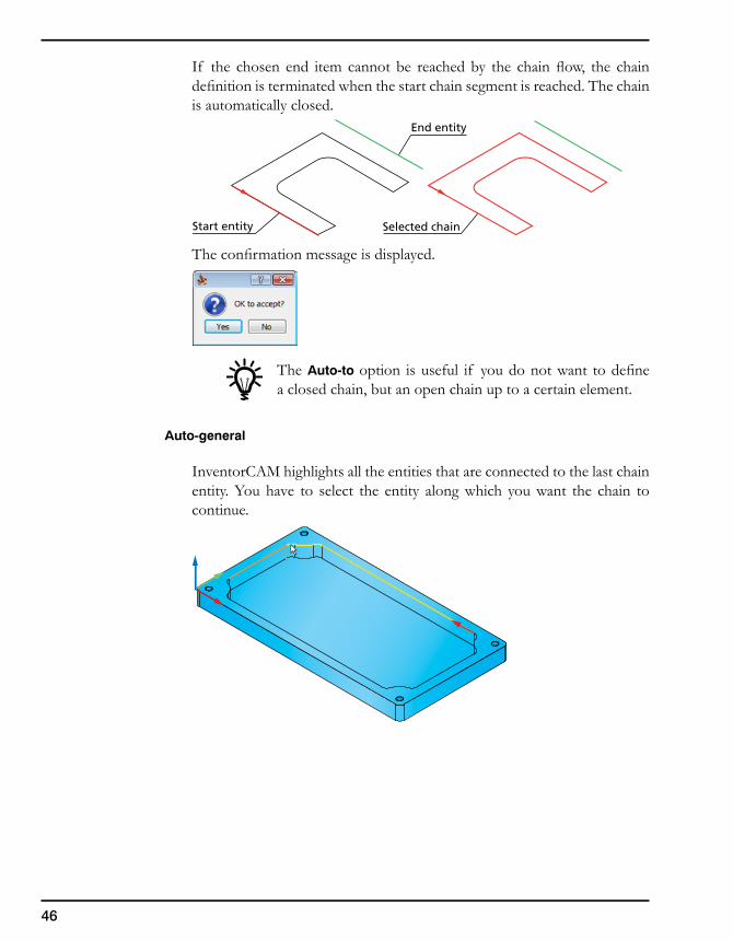
If the chosen end item cannot be reached by the chain flow, the chain definition is terminated when the start chain segment is reached. The chain is automatically closed.
The confirmation message is displayed.
The Auto-to option is useful if you do not want to define a closed chain, but an open chain up to a certain element.
Auto-general
InventorCAM highlights all the entities that are connected to the last chain entity. You have to select the entity along which you want the chain to continue.
Start entity Selected chain
End entity
47
3. InventorCAM 2.5D Operations
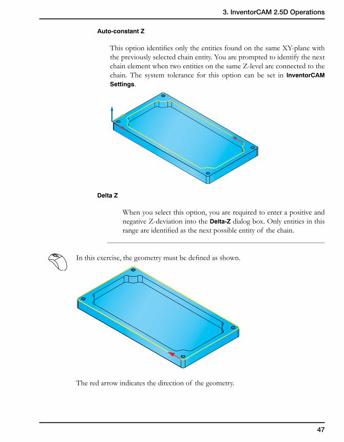
Auto-constant Z
This option identifies only the entities found on the same XY-plane with the previously selected chain entity. You are prompted to identify the next chain element when two entities on the same Z-level are connected to the chain. The system tolerance for this option can be set in InventorCAM Settings.
Delta Z
When you select this option, you are required to enter a positive and negative Z-deviation into the Delta-Z dialog box. Only entities in this range are identified as the next possible entity of the chain.
In this exercise, the geometry must be defined as shown.
The red arrow indicates the direction of the geometry.
48
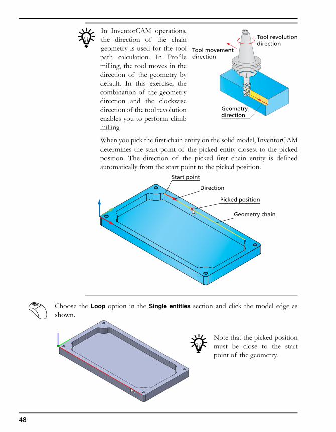
In InventorCAM operations, the direction of the chain geometry is used for the tool path calculation. In Profile milling, the tool moves in the direction of the geometry by default. In this exercise, the combination of the geometry direction and the clockwise direction of the tool revolution enables you to perform climb milling.
When you pick the first chain entity on the solid model, InventorCAM determines the start point of the picked entity closest to the picked position. The direction of the picked first chain entity is defined automatically from the start point to the picked position.
Choose the Loop option in the Single entities section and click the model edge as shown.
Note that the picked position must be close to the start point of the geometry.
Tool revolutiondirection
Tool movementdirection
Geometrydirection
Start point
Direction
Picked position
Geometry chain
49
3. InventorCAM 2.5D Operations
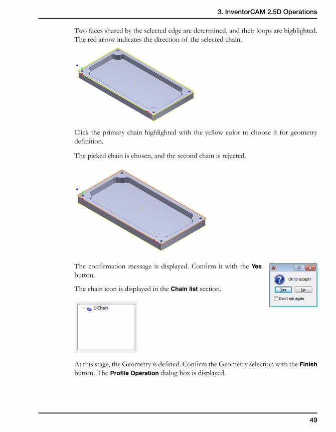
Two faces shared by the selected edge are determined, and their loops are highlighted. The red arrow indicates the direction of the selected chain.
Click the primary chain highlighted with the yellow color to choose it for geometry definition.
The picked chain is chosen, and the second chain is rejected.
The confirmation message is displayed. Confirm it with the Yes button.
The chain icon is displayed in the Chain list section.
At this stage, the Geometry is defined. Confirm the Geometry selection with the Finish button. The Profile Operation dialog box is displayed.
50
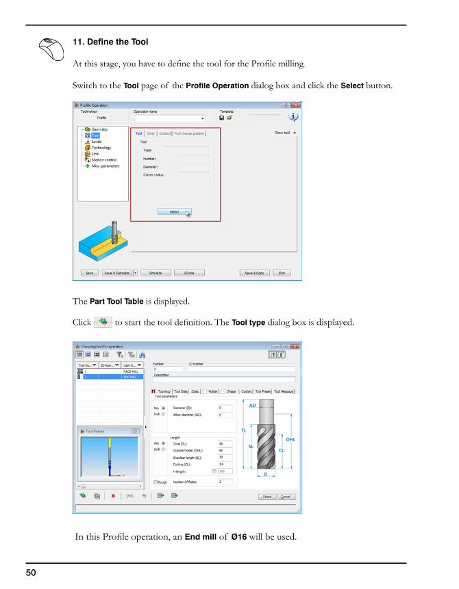
11. Define the Tool
At this stage, you have to define the tool for the Profile milling.
Switch to the Tool page of the Profile Operation dialog box and click the Select button.
The Part Tool Table is displayed.
Click to start the tool definition. The Tool type dialog box is displayed.
In this Profile operation, an End mill of Ø16 will be used.
51
3. InventorCAM 2.5D Operations
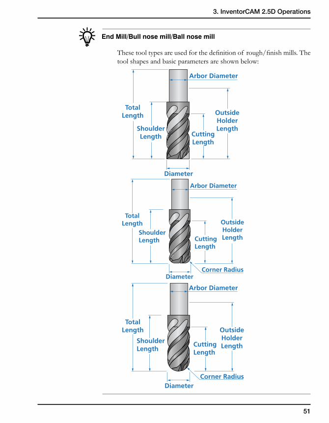
End Mill/Bull nose mill/Ball nose mill
These tool types are used for the definition of rough/finish mills. The tool shapes and basic parameters are shown below:
OutsideHolderLength
CuttingLength
Arbor Diameter
Diameter
TotalLength
ShoulderLength
OutsideHolderLengthCutting
Length
Corner Radius
Arbor Diameter
Diameter
TotalLength
ShoulderLength
OutsideHolderLengthCutting
Length
Corner Radius
Arbor Diameter
Diameter
TotalLength
ShoulderLength
52
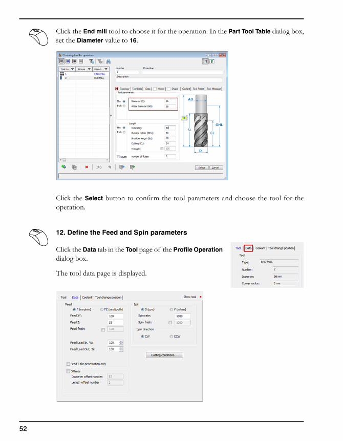
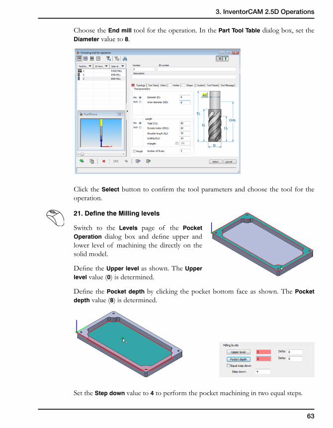
Click the End mill tool to choose it for the operation. In the Part Tool Table dialog box, set the Diameter value to 16.
Click the Select button to confirm the tool parameters and choose the tool for the operation.
12. Define the Feed and Spin parameters
Click the Data tab in the Tool page of the Profile Operation dialog box.
The tool data page is displayed.
53
3. InventorCAM 2.5D Operations
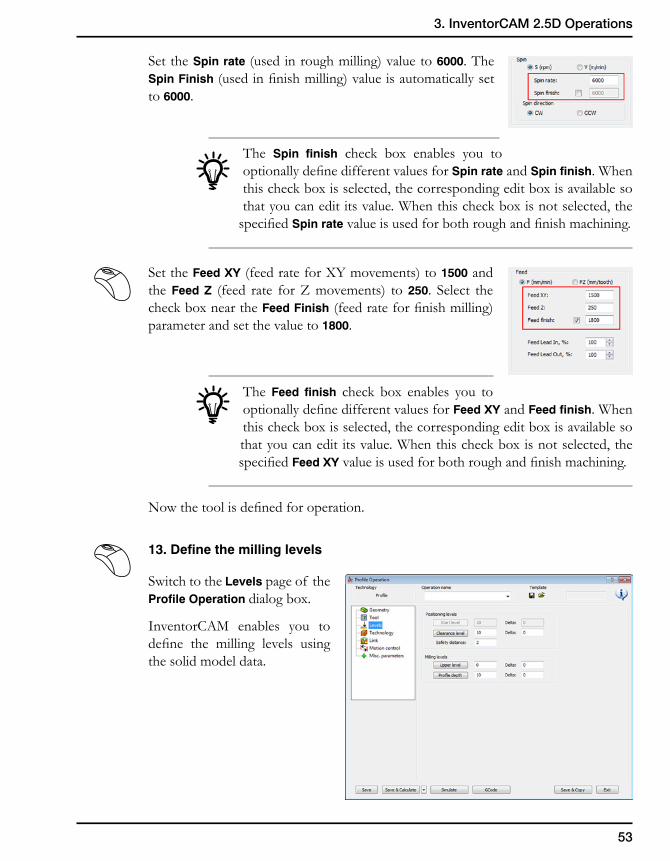
Set the Spin rate (used in rough milling) value to 6000. The Spin Finish (used in finish milling) value is automatically set to 6000.
The Spin finish check box enables you to optionally define different values for Spin rate and Spin finish. When this check box is selected, the corresponding edit box is available so that you can edit its value. When this check box is not selected, the
specified Spin rate value is used for both rough and finish machining.
Set the Feed XY (feed rate for XY movements) to 1500 and the Feed Z (feed rate for Z movements) to 250. Select the check box near the Feed Finish (feed rate for finish milling) parameter and set the value to 1800.
The Feed finish check box enables you to optionally define different values for Feed XY and Feed finish. When this check box is selected, the corresponding edit box is available so that you can edit its value. When this check box is not selected, the specified Feed XY value is used for both rough and finish machining.
Now the tool is defined for operation.
13. Define the milling levels
Switch to the Levels page of the Profile Operation dialog box.
InventorCAM enables you to define the milling levels using the solid model data.
54
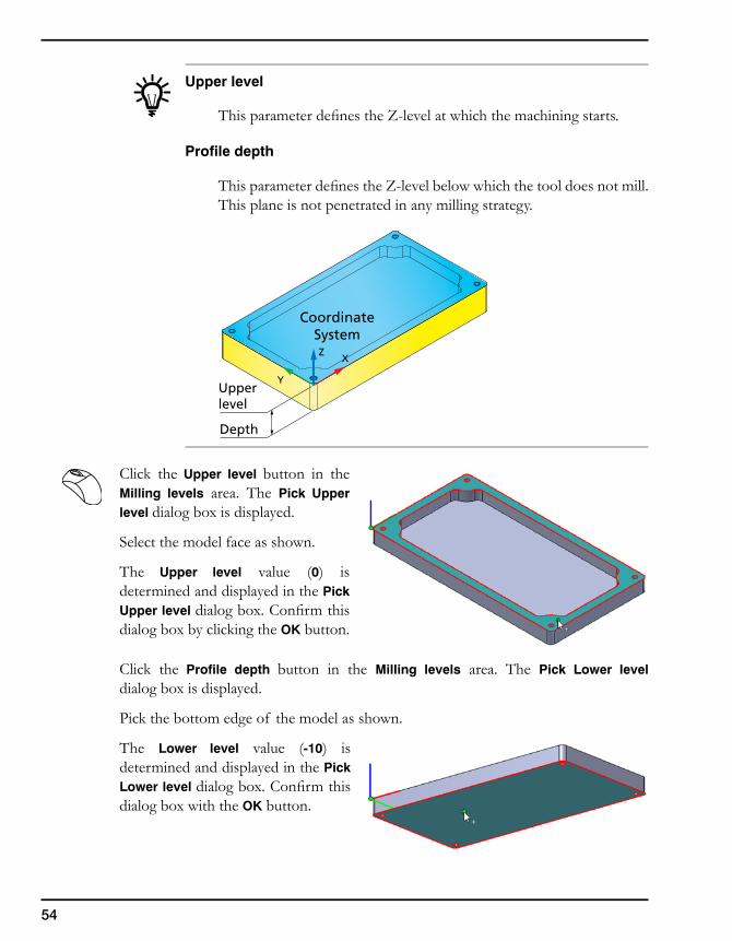
Upper level
This parameter defines the Z-level at which the machining starts.
Profile depth
This parameter defines the Z-level below which the tool does not mill. This plane is not penetrated in any milling strategy.
Click the Upper level button in the Milling levels area. The Pick Upper level dialog box is displayed.
Select the model face as shown.
The Upper level value (0) is determined and displayed in the Pick Upper level dialog box. Confirm this dialog box by clicking the OK button.
Click the Profile depth button in the Milling levels area. The Pick Lower level dialog box is displayed.
Pick the bottom edge of the model as shown.
The Lower level value (-10) is determined and displayed in the Pick Lower level dialog box. Confirm this dialog box with the OK button.
XZ
Y
CoordinateSystem
Upperlevel
Depth
55
3. InventorCAM 2.5D Operations
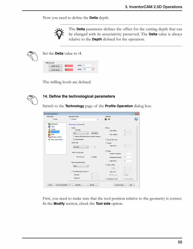
Now you need to define the Delta depth.
The Delta parameter defines the offset for the cutting depth that can be changed with its associativity preserved. The Delta value is always relative to the Depth defined for the operation.
Set the Delta value to -1.
The milling levels are defined.
14. Define the technological parameters
Switch to the Technology page of the Profile Operation dialog box.
First, you need to make sure that the tool position relative to the geometry is correct. In the Modify section, check the Tool side option.
56
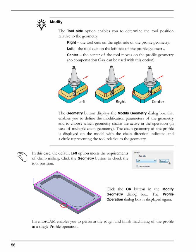
Modify
The Tool side option enables you to determine the tool position relative to the geometry.
Right – the tool cuts on the right side of the profile geometry.Left – the tool cuts on the left side of the profile geometry.Center – the center of the tool moves on the profile geometry (no compensation G4x can be used with this option).
The Geometry button displays the Modify Geometry dialog box that enables you to define the modification parameters of the geometry and to choose which geometry chains are active in the operation (in case of multiple chain geometry). The chain geometry of the profile is displayed on the model with the chain direction indicated and a circle representing the tool relative to the geometry.
In this case, the default Left option meets the requirements of climb milling. Click the Geometry button to check the tool position.
Click the OK button in the Modify Geometry dialog box. The Profile Operation dialog box is displayed again.
InventorCAM enables you to perform the rough and finish machining of the profile in a single Profile operation.
Left Right Center
57
3. InventorCAM 2.5D Operations
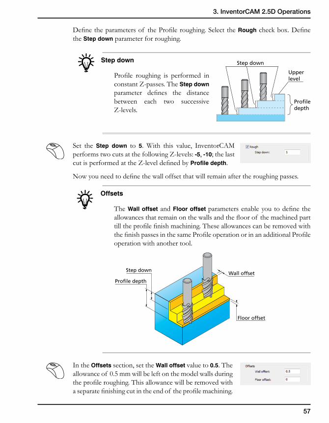
Define the parameters of the Profile roughing. Select the Rough check box. Define the Step down parameter for roughing.
Step down
Profile roughing is performed in constant Z-passes. The Step down parameter defines the distance between each two successive Z-levels.
Set the Step down to 5. With this value, InventorCAM performs two cuts at the following Z-levels: -5, -10; the last cut is performed at the Z-level defined by Profile depth.
Now you need to define the wall offset that will remain after the roughing passes.
Offsets
The Wall offset and Floor offset parameters enable you to define the allowances that remain on the walls and the floor of the machined part till the profile finish machining. These allowances can be removed with the finish passes in the same Profile operation or in an additional Profile operation with another tool.
In the Offsets section, set the Wall offset value to 0.5. The allowance of 0.5 mm will be left on the model walls during the profile roughing. This allowance will be removed with a separate finishing cut in the end of the profile machining.
Step down
Upperlevel
Profiledepth
Step downWall offset
Profile depth
Floor offset
58
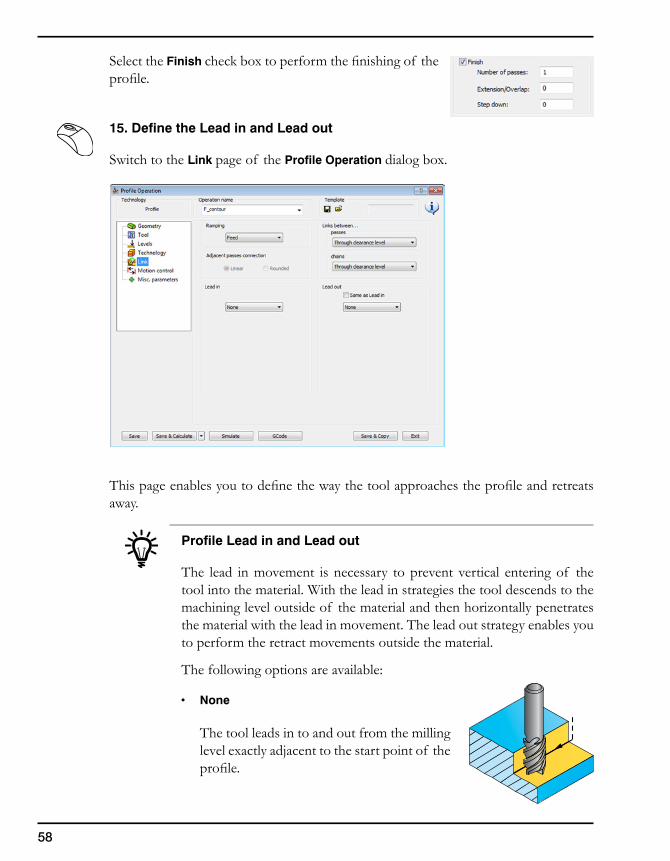
Select the Finish check box to perform the finishing of the profile.
15. Define the Lead in and Lead out
Switch to the Link page of the Profile Operation dialog box.
This page enables you to define the way the tool approaches the profile and retreats away.
Profile Lead in and Lead out
The lead in movement is necessary to prevent vertical entering of the tool into the material. With the lead in strategies the tool descends to the machining level outside of the material and then horizontally penetrates the material with the lead in movement. The lead out strategy enables you to perform the retract movements outside the material.
The following options are available:
• None
The tool leads in to and out from the milling level exactly adjacent to the start point of the profile.
59
3. InventorCAM 2.5D Operations
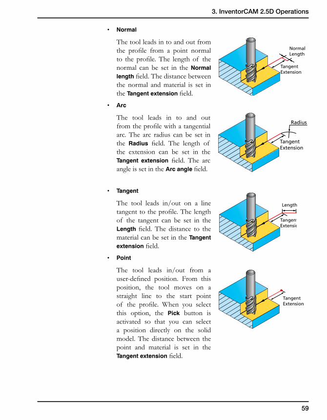
• Normal
The tool leads in to and out from the profile from a point normal to the profile. The length of the normal can be set in the Normal length field. The distance between the normal and material is set in the Tangent extension field.
• Arc
The tool leads in to and out from the profile with a tangential arc. The arc radius can be set in the Radius field. The length of the extension can be set in the Tangent extension field. The arc angle is set in the Arc angle field.
• Tangent
The tool leads in/out on a line tangent to the profile. The length of the tangent can be set in the Length field. The distance to the material can be set in the Tangent extension field.
• Point
The tool leads in/out from a user-defined position. From this position, the tool moves on a straight line to the start point of the profile. When you select this option, the Pick button is activated so that you can select a position directly on the solid model. The distance between the point and material is set in the Tangent extension field.
TangentExtension
Normal Length
Radius
TangentExtension
Tangent Extension
Length
Tangent Extension
60
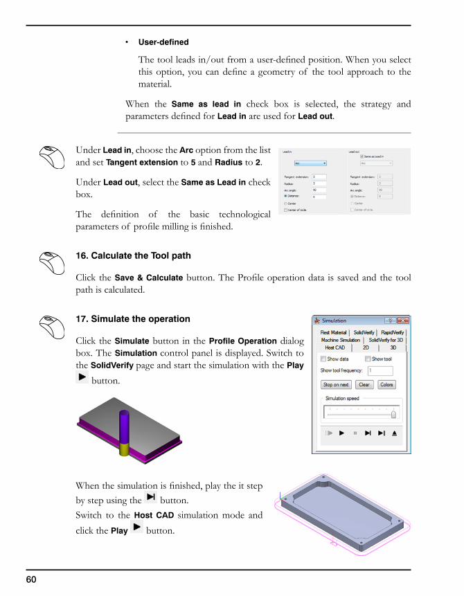
• User-defined
The tool leads in/out from a user-defined position. When you select this option, you can define a geometry of the tool approach to the material.
When the Same as lead in check box is selected, the strategy and parameters defined for Lead in are used for Lead out.
Under Lead in, choose the Arc option from the list and set Tangent extension to 5 and Radius to 2.
Under Lead out, select the Same as Lead in check box.
The definition of the basic technological parameters of profile milling is finished.
16. Calculate the Tool path
Click the Save & Calculate button. The Profile operation data is saved and the tool path is calculated.
17. Simulate the operation
Click the Simulate button in the Profile Operation dialog box. The Simulation control panel is displayed. Switch to the SolidVerify page and start the simulation with the Play
button.
When the simulation is finished, play the it step by step using the button.Switch to the Host CAD simulation mode and click the Play button.
61
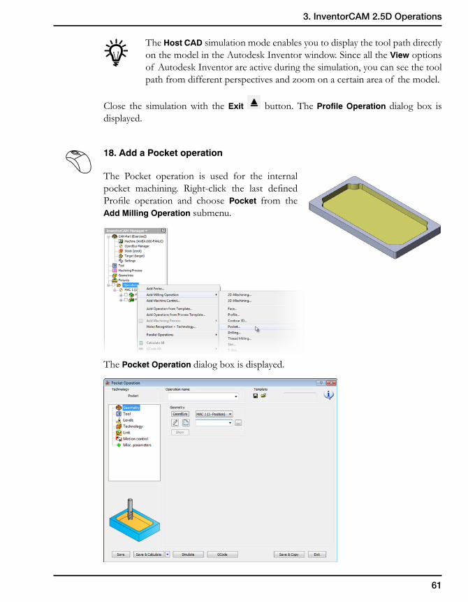
3. InventorCAM 2.5D Operations
The Host CAD simulation mode enables you to display the tool path directly on the model in the Autodesk Inventor window. Since all the View options of Autodesk Inventor are active during the simulation, you can see the tool path from different perspectives and zoom on a certain area of the model.
Close the simulation with the Exit button. The Profile Operation dialog box is displayed.
18. Add a Pocket operation
The Pocket operation is used for the internal pocket machining. Right-click the last defined Profile operation and choose Pocket from the Add Milling Operation submenu.
The Pocket Operation dialog box is displayed.
62
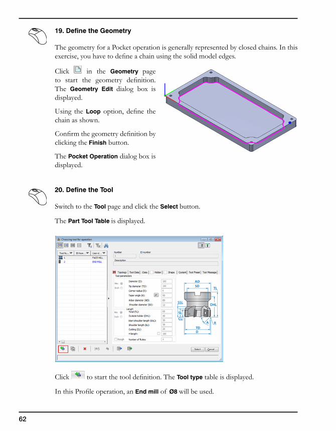
19. Define the Geometry
The geometry for a Pocket operation is generally represented by closed chains. In this exercise, you have to define a chain using the solid model edges.
Click in the Geometry page to start the geometry definition. The Geometry Edit dialog box is displayed.
Using the Loop option, define the chain as shown.
Confirm the geometry definition by clicking the Finish button.
The Pocket Operation dialog box is displayed.
20. Define the Tool
Switch to the Tool page and click the Select button.
The Part Tool Table is displayed.
Click to start the tool definition. The Tool type table is displayed.
In this Profile operation, an End mill of Ø8 will be used.
63
3. InventorCAM 2.5D Operations
Choose the End mill tool for the operation. In the Part Tool Table dialog box, set the Diameter value to 8.
Click the Select button to confirm the tool parameters and choose the tool for the operation.
21. Define the Milling levels
Switch to the Levels page of the Pocket Operation dialog box and define upper and lower level of machining the directly on the solid model.
Define the Upper level as shown. The Upper level value (0) is determined.
Define the Pocket depth by clicking the pocket bottom face as shown. The Pocket depth value (8) is determined.
Set the Step down value to 4 to perform the pocket machining in two equal steps.
64
22. Define the technological parameters
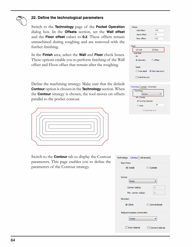
Switch to the Technology page of the Pocket Operation dialog box. In the Offsets section, set the Wall offset and the Floor offset values to 0.2. These offsets remain unmachined during roughing and are removed with the further finishing.
In the Finish area, select the Wall and Floor check boxes. These options enable you to perform finishing of the Wall offset and Floor offset that remain after the roughing.
Define the machining strategy. Make sure that the default Contour option is chosen in the Technology section. When the Contour strategy is chosen, the tool moves on offsets parallel to the pocket contour.
Switch to the Contour tab to display the Contour parameters. This page enables you to define the parameters of the Contour strategy.
65
3. InventorCAM 2.5D Operations
Contour parameters
Start from
• Inside
This option allows you to work in a pocket area starting from the middle of the pocket and cutting towards the outside border of the pocket.
• Outside
This option allows you to work in a pocket area starting from the outside border of the pocket and cutting towards the middle of the pocket.
Corner
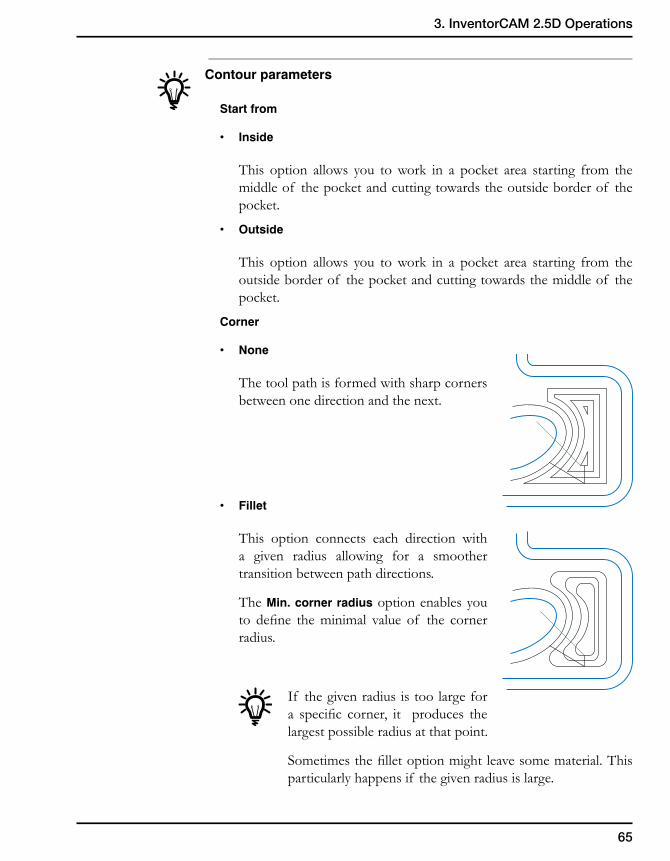
• None
The tool path is formed with sharp corners between one direction and the next.
• Fillet
This option connects each direction with a given radius allowing for a smoother transition between path directions.
The Min. corner radius option enables you to define the minimal value of the corner radius.
If the given radius is too large for a specific corner, it produces the largest possible radius at that point.
Sometimes the fillet option might leave some material. This particularly happens if the given radius is large.
66
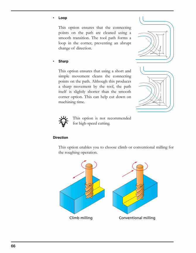
• Loop
This option ensures that the connecting points on the path are cleaned using a smooth transition. The tool path forms a loop in the corner, preventing an abrupt change of direction.
• Sharp
This option ensures that using a short and simple movement cleans the connecting points on the path. Although this produces a sharp movement by the tool, the path itself is slightly shorter than the smooth corner option. This can help cut down on machining time.
This option is not recommended for high-speed cutting.
Direction
This option enables you to choose climb or conventional milling for the roughing operation.
Climb milling Conventional milling

67
3. InventorCAM 2.5D Operations
Adjacent passes connection
This option enables you to choose the method of the tool movement within the pocket from one tool path pass to the next one.
• Linear
The tool performs normal approach from one tool path pass to the next one.
• Rounded
The tool performs an arc movement from one tool path pass to the next one. The radius of the arc is half the distance between the tool path passes.
• Smooth
The tool performs a smooth movement from one tool path pass to the next one.
68
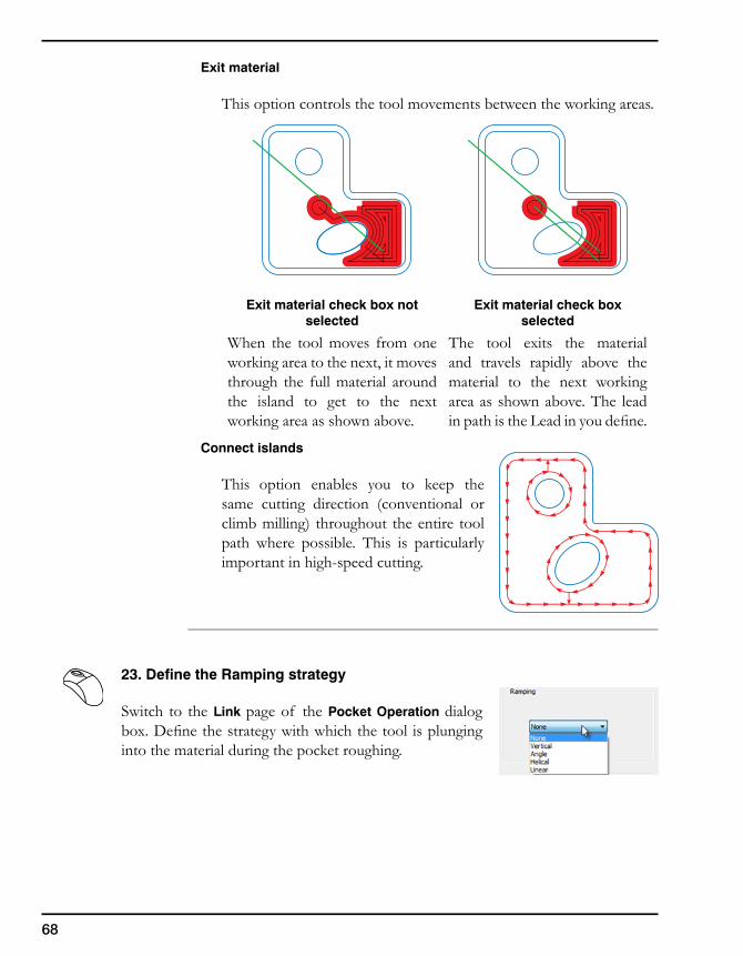
Exit material
This option controls the tool movements between the working areas.
Exit material check box not selected
Exit material check box selected
When the tool moves from one working area to the next, it moves through the full material around the island to get to the next working area as shown above.
The tool exits the material and travels rapidly above the material to the next working area as shown above. The lead in path is the Lead in you define.
Connect islands
This option enables you to keep the same cutting direction (conventional or climb milling) throughout the entire tool path where possible. This is particularly important in high-speed cutting.
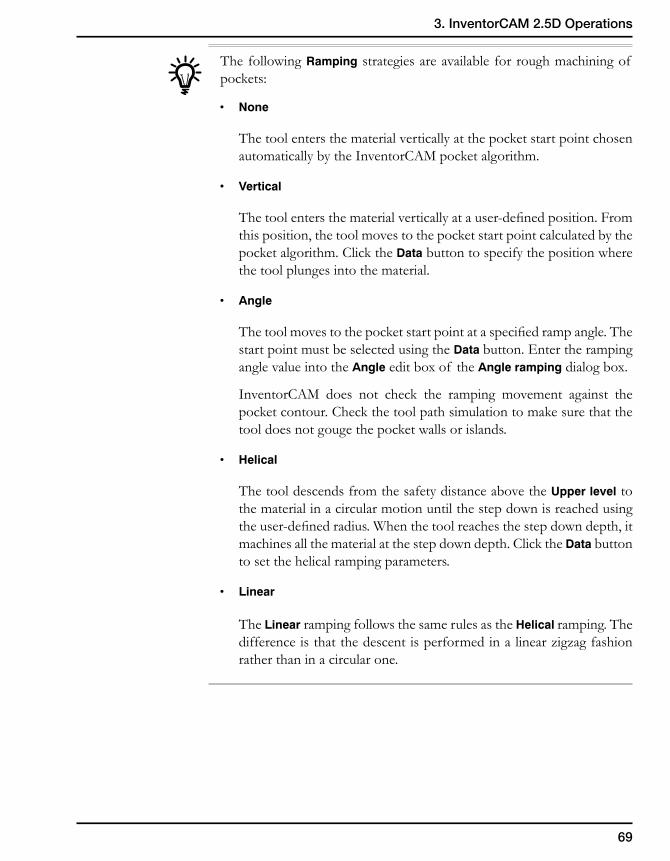
23. Define the Ramping strategy
Switch to the Link page of the Pocket Operation dialog box. Define the strategy with which the tool is plunging into the material during the pocket roughing.
69
3. InventorCAM 2.5D Operations
The following Ramping strategies are available for rough machining of pockets:
• None
The tool enters the material vertically at the pocket start point chosen automatically by the InventorCAM pocket algorithm.
• Vertical
The tool enters the material vertically at a user-defined position. From this position, the tool moves to the pocket start point calculated by the pocket algorithm. Click the Data button to specify the position where the tool plunges into the material.
• Angle
The tool moves to the pocket start point at a specified ramp angle. The start point must be selected using the Data button. Enter the ramping angle value into the Angle edit box of the Angle ramping dialog box.
InventorCAM does not check the ramping movement against the pocket contour. Check the tool path simulation to make sure that the tool does not gouge the pocket walls or islands.
• Helical
The tool descends from the safety distance above the Upper level to the material in a circular motion until the step down is reached using the user-defined radius. When the tool reaches the step down depth, it machines all the material at the step down depth. Click the Data button to set the helical ramping parameters.
• Linear
The Linear ramping follows the same rules as the Helical ramping. The difference is that the descent is performed in a linear zigzag fashion rather than in a circular one.
70
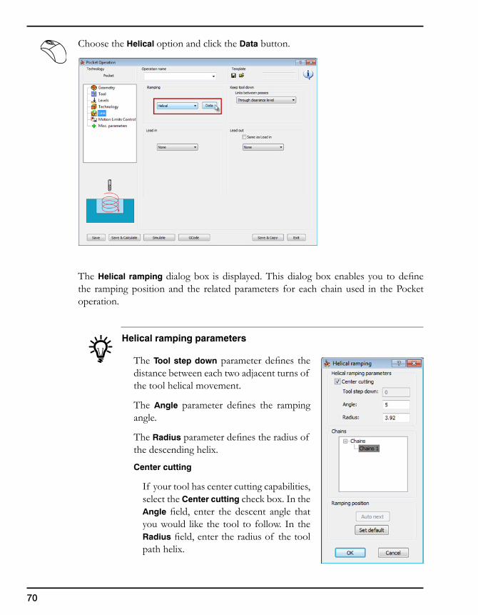
Choose the Helical option and click the Data button.
The Helical ramping dialog box is displayed. This dialog box enables you to define the ramping position and the related parameters for each chain used in the Pocket operation.
Helical ramping parameters
The Tool step down parameter defines the distance between each two adjacent turns of the tool helical movement.
The Angle parameter defines the ramping angle.
The Radius parameter defines the radius of the descending helix.
Center cutting
If your tool has center cutting capabilities, select the Center cutting check box. In the Angle field, enter the descent angle that you would like the tool to follow. In the Radius field, enter the radius of the tool path helix.
71
3. InventorCAM 2.5D Operations
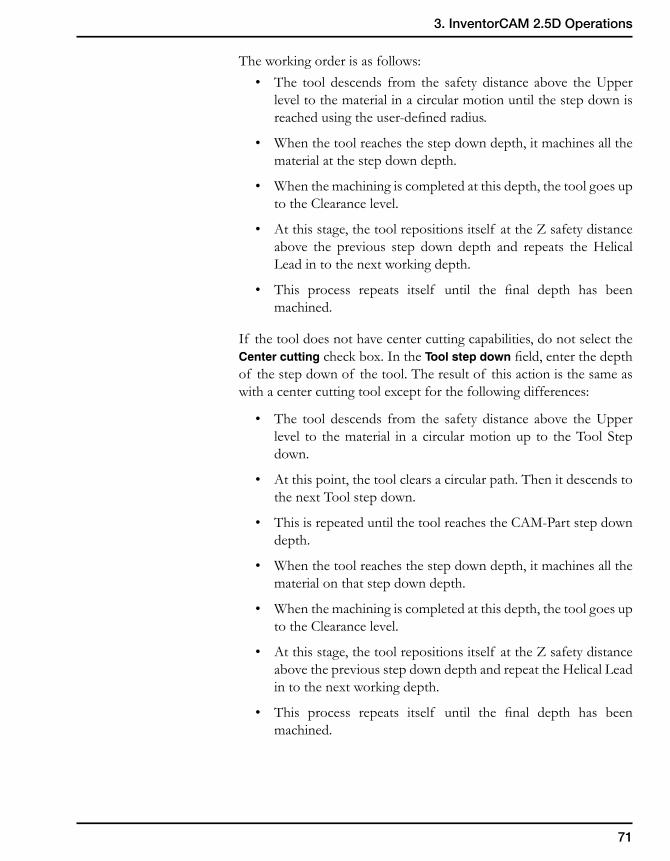
The working order is as follows:• The tool descends from the safety distance above the Upper
level to the material in a circular motion until the step down is reached using the user-defined radius.
• When the tool reaches the step down depth, it machines all the material at the step down depth.
• When the machining is completed at this depth, the tool goes up to the Clearance level.
• At this stage, the tool repositions itself at the Z safety distance above the previous step down depth and repeats the Helical Lead in to the next working depth.
• This process repeats itself until the final depth has been machined.
If the tool does not have center cutting capabilities, do not select the Center cutting check box. In the Tool step down field, enter the depth of the step down of the tool. The result of this action is the same as with a center cutting tool except for the following differences:
• The tool descends from the safety distance above the Upper level to the material in a circular motion up to the Tool Step down.
• At this point, the tool clears a circular path. Then it descends to the next Tool step down.
• This is repeated until the tool reaches the CAM-Part step down depth.
• When the tool reaches the step down depth, it machines all the material on that step down depth.
• When the machining is completed at this depth, the tool goes up to the Clearance level.
• At this stage, the tool repositions itself at the Z safety distance above the previous step down depth and repeat the Helical Lead in to the next working depth.
• This process repeats itself until the final depth has been machined.
72
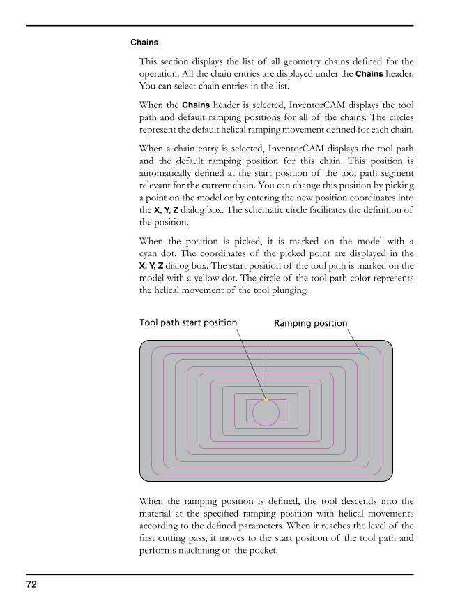
Tool path start position Ramping position
Chains
This section displays the list of all geometry chains defined for the operation. All the chain entries are displayed under the Chains header. You can select chain entries in the list.
When the Chains header is selected, InventorCAM displays the tool path and default ramping positions for all of the chains. The circles represent the default helical ramping movement defined for each chain.
When a chain entry is selected, InventorCAM displays the tool path and the default ramping position for this chain. This position is automatically defined at the start position of the tool path segment relevant for the current chain. You can change this position by picking a point on the model or by entering the new position coordinates into the X, Y, Z dialog box. The schematic circle facilitates the definition of the position.
When the position is picked, it is marked on the model with a cyan dot. The coordinates of the picked point are displayed in the X, Y, Z dialog box. The start position of the tool path is marked on the model with a yellow dot. The circle of the tool path color represents the helical movement of the tool plunging.
When the ramping position is defined, the tool descends into the material at the specified ramping position with helical movements according to the defined parameters. When it reaches the level of the first cutting pass, it moves to the start position of the tool path and performs machining of the pocket.
73
3. InventorCAM 2.5D Operations
Ramping position
The Set default button enables you to replace the currently defined ramping position for the selected chain by the default ramping position located at the tool path start position.
The Auto next button provides you with the selection mode that enables you to define the ramping positions for all of the chains one by one.
Confirm the dialog box with the OK button.
24. Define the Lead out
The Lead out strategies are used for defining the horizontal retreat of the tool from the geometry in the finish machining of the part walls.
Pocket Lead out
The following Lead out strategies are available for pocket machining:
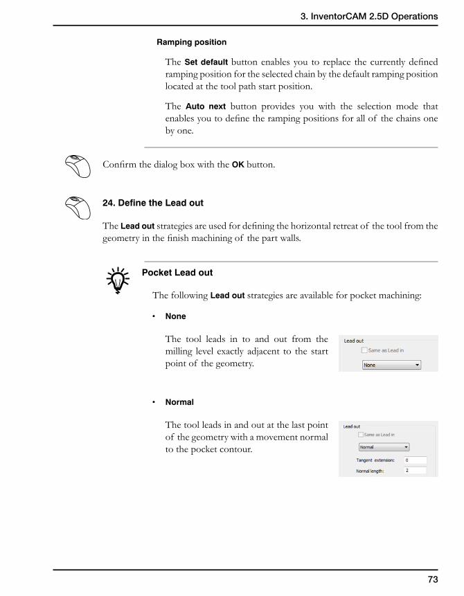
• None
The tool leads in to and out from the milling level exactly adjacent to the start point of the geometry.
• Normal
The tool leads in and out at the last point of the geometry with a movement normal to the pocket contour.
74
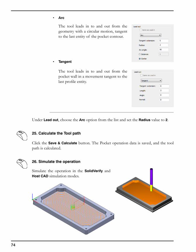
• Arc
The tool leads in to and out from the geometry with a circular motion, tangent to the last entity of the pocket contour.
• Tangent
The tool leads in to and out from the pocket wall in a movement tangent to the last profile entity.
Under Lead out, choose the Arc option from the list and set the Radius value to 2.
25. Calculate the Tool path
Click the Save & Calculate button. The Pocket operation data is saved, and the tool path is calculated.
26. Simulate the operation
Simulate the operation in the SolidVerify and Host CAD simulation modes.
75
3. InventorCAM 2.5D Operations
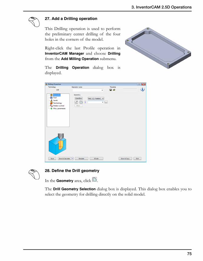
27. Add a Drilling operation
This Drilling operation is used to perform the preliminary center drilling of the four holes in the corners of the model.
Right-click the last Profile operation in InventorCAM Manager and choose Drilling from the Add Milling Operation submenu.
The Drilling Operation dialog box is displayed.
28. Define the Drill geometry
In the Geometry area, click .
The Drill Geometry Selection dialog box is displayed. This dialog box enables you to select the geometry for drilling directly on the solid model.
76
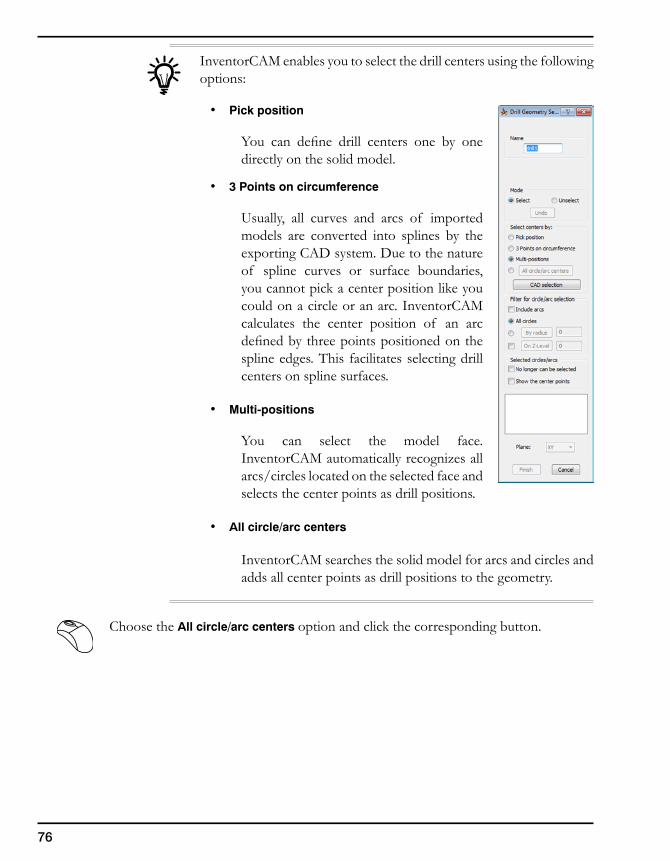
InventorCAM enables you to select the drill centers using the following options:
• Pick position
You can define drill centers one by one directly on the solid model.
• 3 Points on circumference
Usually, all curves and arcs of imported models are converted into splines by the exporting CAD system. Due to the nature of spline curves or surface boundaries, you cannot pick a center position like you could on a circle or an arc. InventorCAM calculates the center position of an arc defined by three points positioned on the spline edges. This facilitates selecting drill centers on spline surfaces.
• Multi-positions
You can select the model face. InventorCAM automatically recognizes all arcs/circles located on the selected face and selects the center points as drill positions.
• All circle/arc centers
InventorCAM searches the solid model for arcs and circles and adds all center points as drill positions to the geometry.
Choose the All circle/arc centers option and click the corresponding button.
77
3. InventorCAM 2.5D Operations
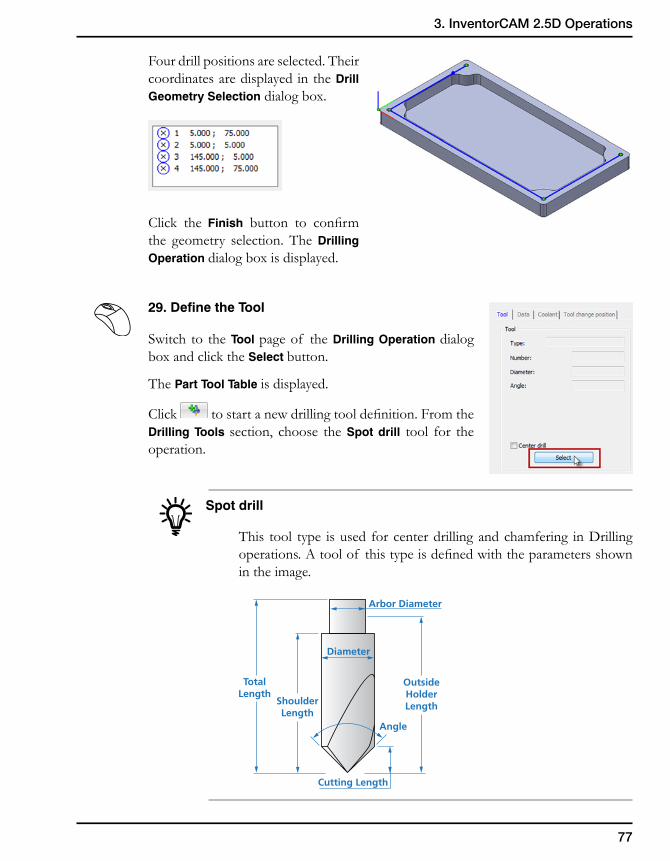
Four drill positions are selected. Their coordinates are displayed in the Drill Geometry Selection dialog box.
Click the Finish button to confirm the geometry selection. The Drilling Operation dialog box is displayed.
29. Define the Tool
Switch to the Tool page of the Drilling Operation dialog box and click the Select button.
The Part Tool Table is displayed.
Click to start a new drilling tool definition. From the Drilling Tools section, choose the Spot drill tool for the operation.
Spot drill
This tool type is used for center drilling and chamfering in Drilling operations. A tool of this type is defined with the parameters shown in the image.
OutsideHolderLength
Cutting Length
Diameter
Angle
TotalLength
ShoulderLength
Arbor Diameter
78
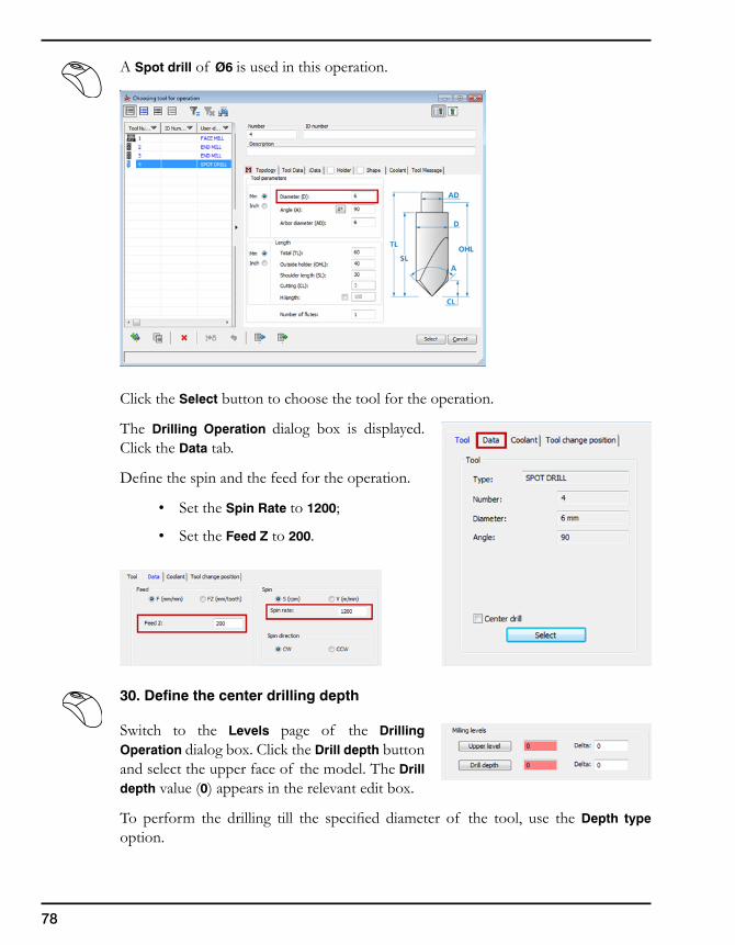
A Spot drill of Ø6 is used in this operation.
Click the Select button to choose the tool for the operation.
The Drilling Operation dialog box is displayed. Click the Data tab.
Define the spin and the feed for the operation.
• Set the Spin Rate to 1200;
• Set the Feed Z to 200.
30. Define the center drilling depth
Switch to the Levels page of the Drilling Operation dialog box. Click the Drill depth button and select the upper face of the model. The Drill depth value (0) appears in the relevant edit box.
To perform the drilling till the specified diameter of the tool, use the Depth type option.
79
3. InventorCAM 2.5D Operations
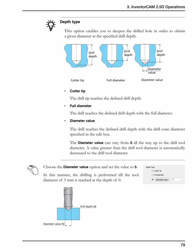
Depth type
This option enables you to deepen the drilled hole in order to obtain a given diameter at the specified drill depth.
• Cuttertip
The drill tip reaches the defined drill depth.
• Fulldiameter
The drill reaches the defined drill depth with the full diameter.
• Diametervalue
The drill reaches the defined drill depth with the drill cone diameter specified in the edit box.
The Diameter value can vary from 0 all the way up to the drill tool diameter. A value greater than the drill tool diameter is automatically decreased to the drill tool diameter.
Choose the Diameter value option and set the value to 5.
In this manner, the drilling is performed till the tool diameter of 5 mm is reached at the depth of 0.
Drilldepth
Cutter tip Full diameter Diameter value
Drilldepth
Drilldepth
Diametervalue
Diameter value (5)
Drill depth (0)
80
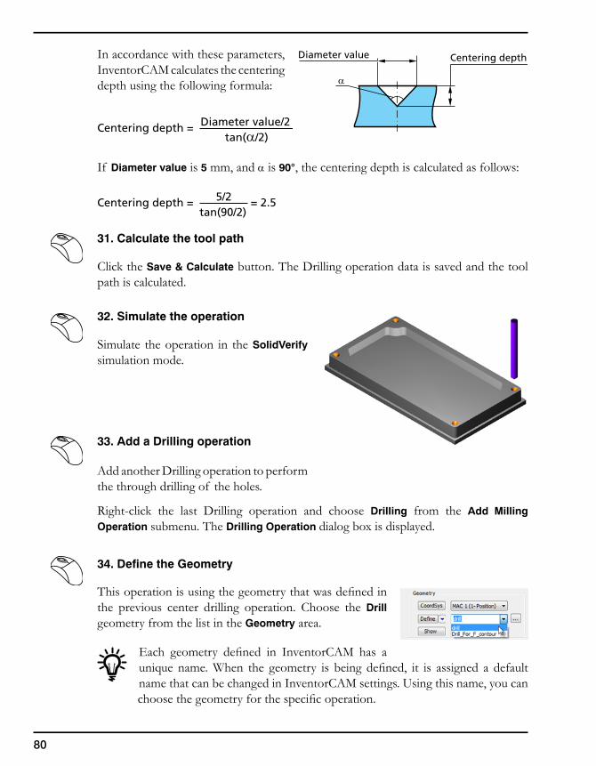
Centering depth = 5/2tan(90/2)
= 2.5
Diameter value
α
Centering depth
Centering depth = Diameter value/2tan(α/2)
In accordance with these parameters, InventorCAM calculates the centering depth using the following formula:
If Diameter value is 5 mm, and α is 90°, the centering depth is calculated as follows:
31. Calculate the tool path
Click the Save & Calculate button. The Drilling operation data is saved and the tool path is calculated.
32. Simulate the operation
Simulate the operation in the SolidVerify simulation mode.
33. Add a Drilling operation
Add another Drilling operation to perform the through drilling of the holes.
Right-click the last Drilling operation and choose Drilling from the Add Milling Operation submenu. The Drilling Operation dialog box is displayed.
34. Define the Geometry
This operation is using the geometry that was defined in the previous center drilling operation. Choose the Drill geometry from the list in the Geometry area.
Each geometry defined in InventorCAM has a unique name. When the geometry is being defined, it is assigned a default name that can be changed in InventorCAM settings. Using this name, you can choose the geometry for the specific operation.
81
3. InventorCAM 2.5D Operations
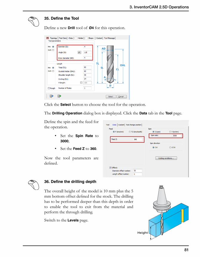
35. Define the Tool
Define a new Drill tool of Ø4 for this operation.
Click the Select button to choose the tool for the operation.
The Drilling Operation dialog box is displayed. Click the Data tab in the Tool page.
Define the spin and the feed for the operation.
• Set the Spin Rate to 3000;
• Set the Feed Z to 360.
Now the tool parameters are defined.
36. Define the drilling depth
The overall height of the model is 10 mm plus the 5 mm bottom offset defined for the stock. The drilling has to be performed deeper than this depth in order to enable the tool to exit from the material and perform the through drilling.
Switch to the Levels page.
Height
82
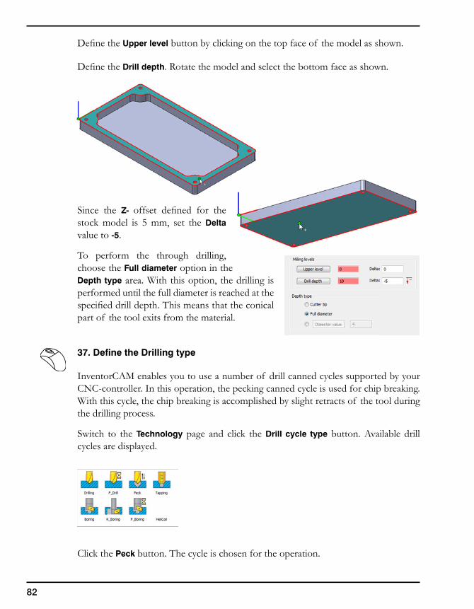
Define the Upper level button by clicking on the top face of the model as shown.
Define the Drill depth. Rotate the model and select the bottom face as shown.
Since the Z- offset defined for the stock model is 5 mm, set the Delta value to -5.
To perform the through drilling, choose the Full diameter option in the Depth type area. With this option, the drilling is performed until the full diameter is reached at the specified drill depth. This means that the conical part of the tool exits from the material.
37. Define the Drilling type
InventorCAM enables you to use a number of drill canned cycles supported by your CNC-controller. In this operation, the pecking canned cycle is used for chip breaking. With this cycle, the chip breaking is accomplished by slight retracts of the tool during the drilling process.
Switch to the Technology page and click the Drill cycle type button. Available drill cycles are displayed.
Click the Peck button. The cycle is chosen for the operation.
83
3. InventorCAM 2.5D Operations
Click the Data button to define the pecking parameters. The Drill Options dialog box is displayed. Set the Step down to 1.5 in order to define the depth of each pecking movement. Confirm the data with the OK button.
38. Calculate the tool path
Click the Save & Calculate button.
The Drilling operation data is saved and the tool path is calculated.
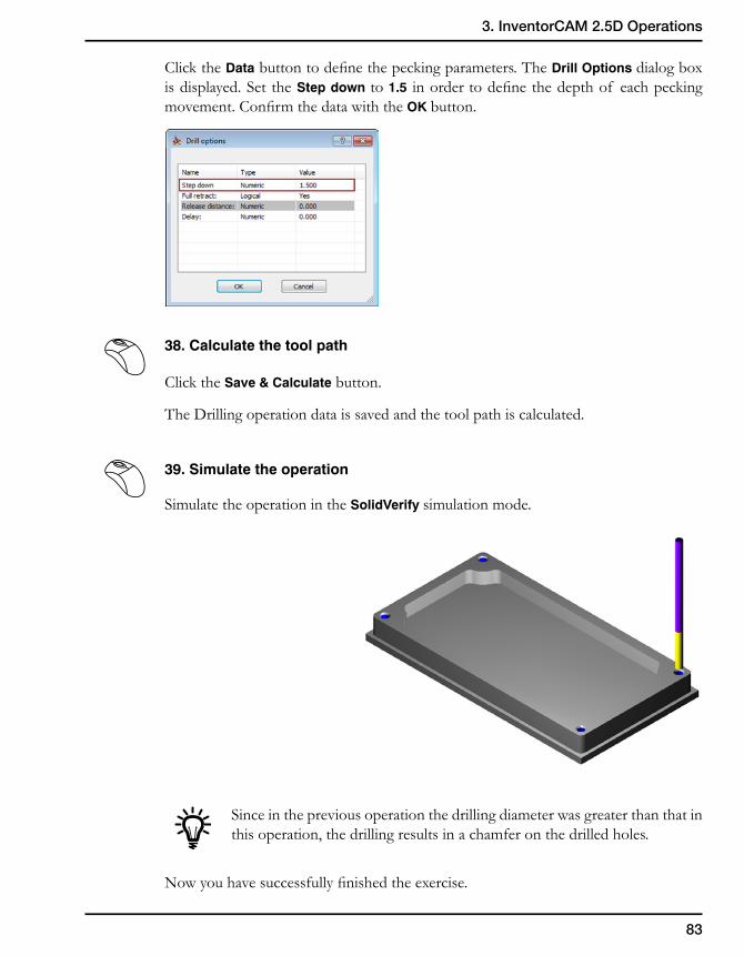
39. Simulate the operation
Simulate the operation in the SolidVerify simulation mode.
Since in the previous operation the drilling diameter was greater than that in this operation, the drilling results in a chamfer on the drilled holes.
Now you have successfully finished the exercise.
84
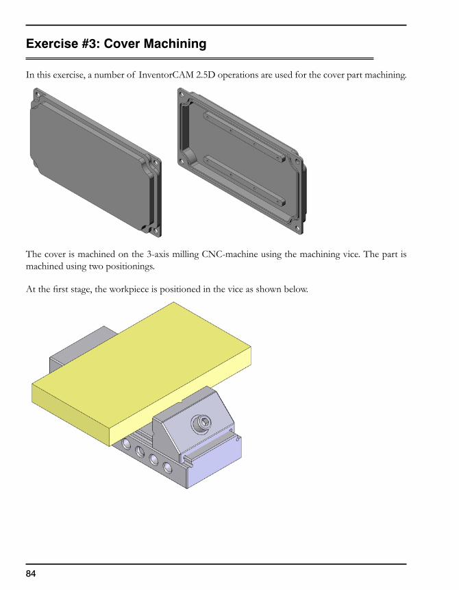
Exercise #3: Cover Machining
In this exercise, a number of InventorCAM 2.5D operations are used for the cover part machining.
The cover is machined on the 3-axis milling CNC-machine using the machining vice. The part is machined using two positionings.
At the first stage, the workpiece is positioned in the vice as shown below.
85
3. InventorCAM 2.5D Operations
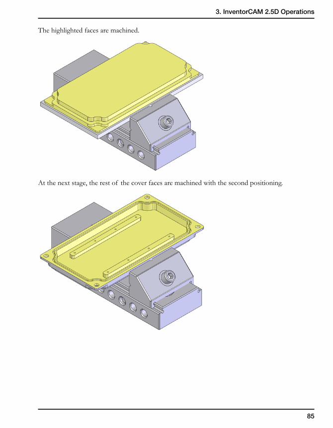
The highlighted faces are machined.
At the next stage, the rest of the cover faces are machined with the second positioning.
86
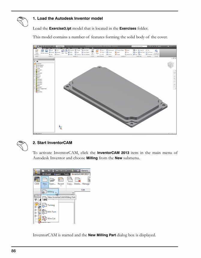
1. Load the Autodesk Inventor model
Load the Exercise3.ipt model that is located in the Exercises folder.
This model contains a number of features forming the solid body of the cover.
2. Start InventorCAM
To activate InventorCAM, click the InventorCAM 2013 item in the main menu of Autodesk Inventor and choose Milling from the New submenu.
InventorCAM is started and the New Milling Part dialog box is displayed.
87
3. InventorCAM 2.5D Operations
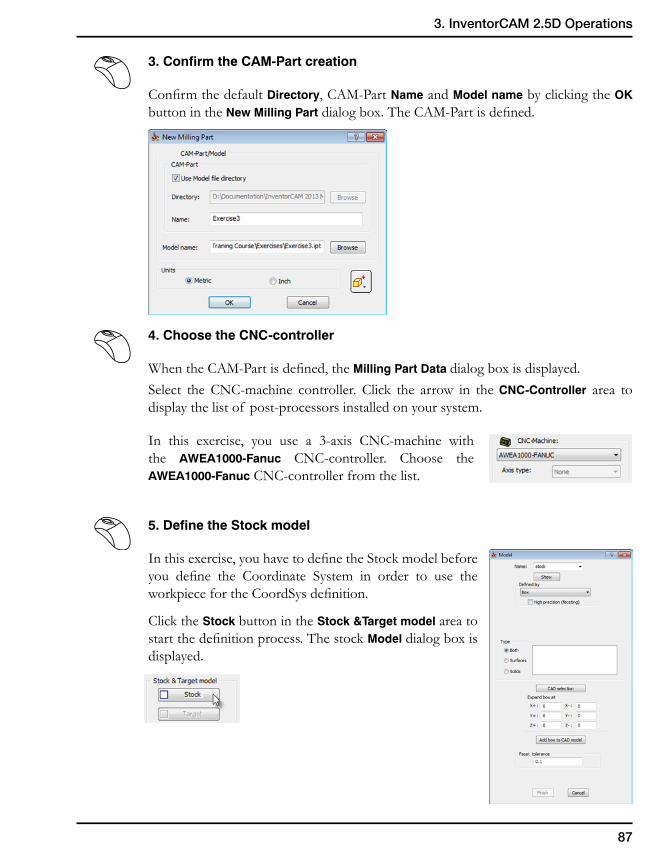
3. Confirm the CAM-Part creation
Confirm the default Directory, CAM-Part Name and Model name by clicking the OK button in the New Milling Part dialog box. The CAM-Part is defined.
4. Choose the CNC-controller
When the CAM-Part is defined, the Milling Part Data dialog box is displayed.Select the CNC-machine controller. Click the arrow in the CNC-Controller area to display the list of post-processors installed on your system.
In this exercise, you use a 3-axis CNC-machine with the AWEA1000-Fanuc CNC-controller. Choose the AWEA1000-Fanuc CNC-controller from the list.
5. Define the Stock model
In this exercise, you have to define the Stock model before you define the Coordinate System in order to use the workpiece for the CoordSys definition.
Click the Stock button in the Stock &Target model area to start the definition process. The stock Model dialog box is displayed.
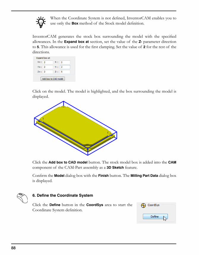
88
When the Coordinate System is not defined, InventorCAM enables you to use only the Box method of the Stock model definition.
InventorCAM generates the stock box surrounding the model with the specified allowances. In the Expand box at section, set the value of the Z- parameter direction to 5. This allowance is used for the first clamping. Set the value of 2 for the rest of the directions.
Click on the model. The model is highlighted, and the box surrounding the model is displayed.
Click the Add box to CAD model button. The stock model box is added into the CAM component of the CAM-Part assembly as a 3D Sketch feature.
Confirm the Model dialog box with the Finish button. The Milling Part Data dialog box is displayed.
6. Define the Coordinate System
Click the Define button in the CoordSys area to start the Coordinate System definition.
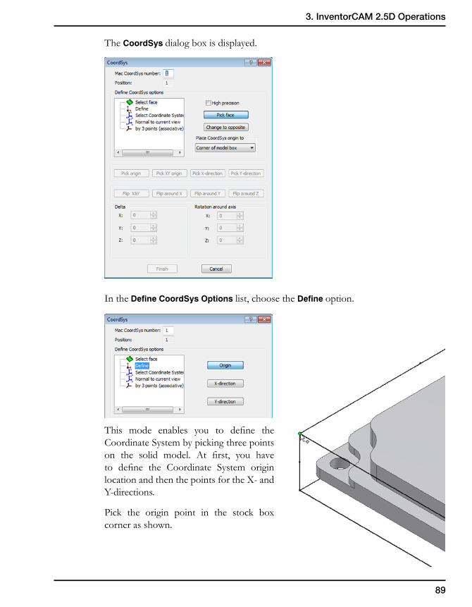
89
3. InventorCAM 2.5D Operations
The CoordSys dialog box is displayed.
In the Define CoordSys Options list, choose the Define option.
This mode enables you to define the Coordinate System by picking three points on the solid model. At first, you have to define the Coordinate System origin location and then the points for the X- and Y-directions.
Pick the origin point in the stock box corner as shown.
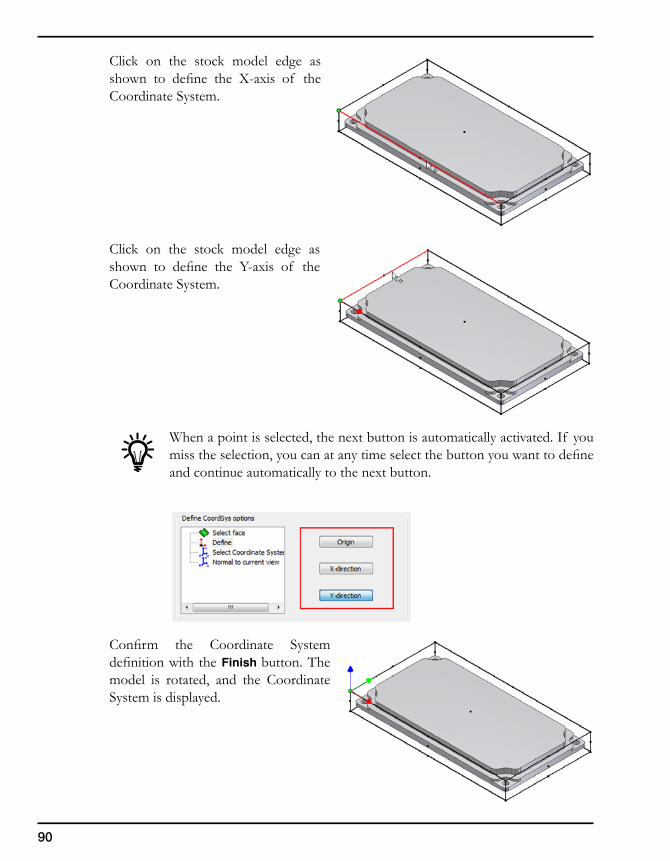
90
Click on the stock model edge as shown to define the X-axis of the Coordinate System.
Click on the stock model edge as shown to define the Y-axis of the Coordinate System.
When a point is selected, the next button is automatically activated. If you miss the selection, you can at any time select the button you want to define and continue automatically to the next button.
Confirm the Coordinate System definition with the Finish button. The model is rotated, and the Coordinate System is displayed.
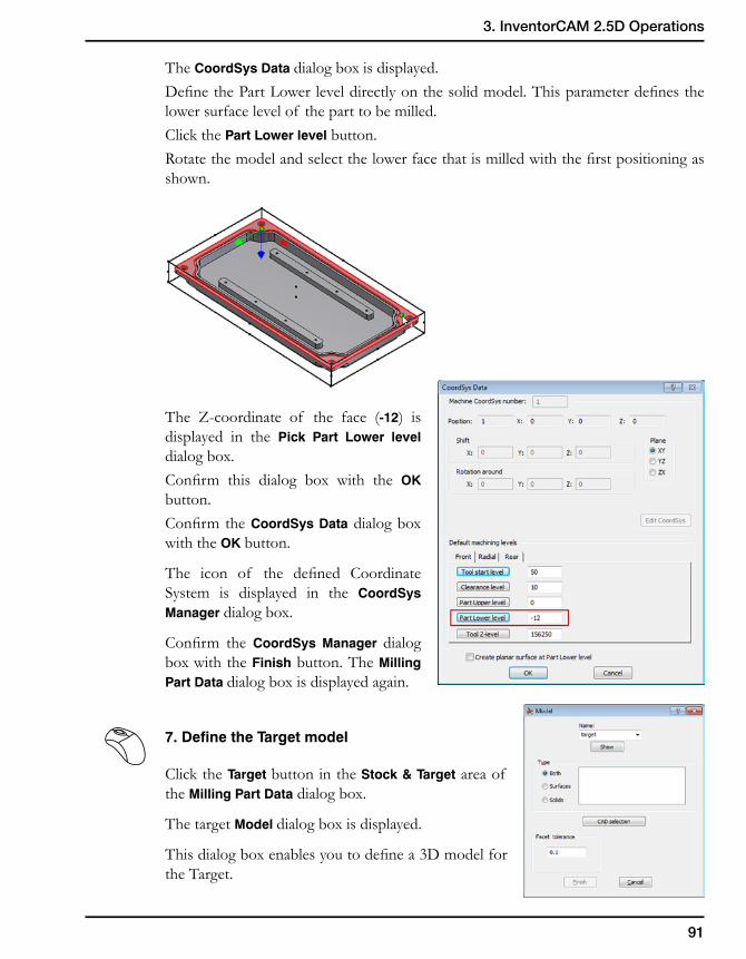
91
3. InventorCAM 2.5D Operations
The CoordSys Data dialog box is displayed.Define the Part Lower level directly on the solid model. This parameter defines the lower surface level of the part to be milled.Click the Part Lower level button.Rotate the model and select the lower face that is milled with the first positioning as shown.
The Z-coordinate of the face (-12) is displayed in the Pick Part Lower level dialog box.Confirm this dialog box with the OK button.Confirm the CoordSys Data dialog box with the OK button.
The icon of the defined Coordinate System is displayed in the CoordSys Manager dialog box.
Confirm the CoordSys Manager dialog box with the Finish button. The Milling Part Data dialog box is displayed again.
7. Define the Target model
Click the Target button in the Stock & Target area of the Milling Part Data dialog box.
The target Model dialog box is displayed.
This dialog box enables you to define a 3D model for the Target.
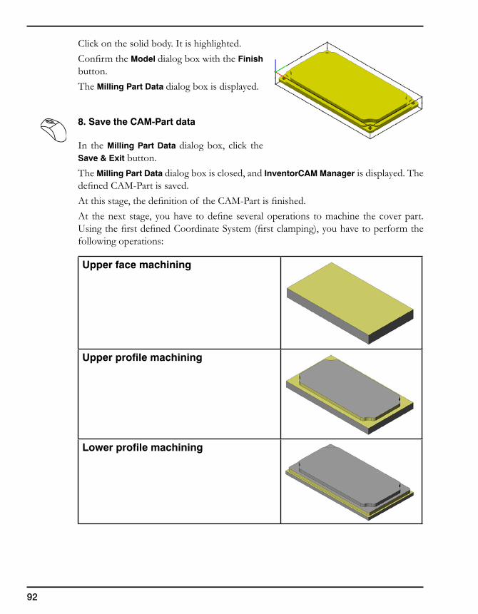
92
Click on the solid body. It is highlighted.Confirm the Model dialog box with the Finish button.The Milling Part Data dialog box is displayed.
8. Save the CAM-Part data
In the Milling Part Data dialog box, click the Save & Exit button.The Milling Part Data dialog box is closed, and InventorCAM Manager is displayed. The defined CAM-Part is saved.At this stage, the definition of the CAM-Part is finished.At the next stage, you have to define several operations to machine the cover part. Using the first defined Coordinate System (first clamping), you have to perform the following operations:
Upper face machining
Upper profile machining
Lower profile machining
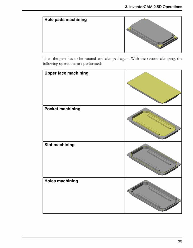
93
3. InventorCAM 2.5D Operations
Hole pads machining
Then the part has to be rotated and clamped again. With the second clamping, the following operations are performed:
Upper face machining
Pocket machining
Slot machining
Holes machining
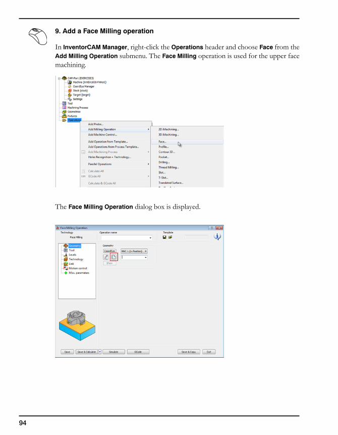
94
9. Add a Face Milling operation
In InventorCAM Manager, right-click the Operations header and choose Face from the Add Milling Operation submenu. The Face Milling operation is used for the upper face machining.
The Face Milling Operation dialog box is displayed.
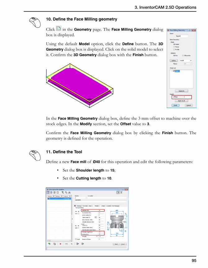
95
3. InventorCAM 2.5D Operations
10. Define the Face Milling geometry
Click in the Geometry page. The Face Milling Geometry dialog box is displayed.
Using the default Model option, click the Define button. The 3D Geometry dialog box is displayed. Click on the solid model to select it. Confirm the 3D Geometry dialog box with the Finish button.
In the Face Milling Geometry dialog box, define the 3 mm offset to machine over the stock edges. In the Modify section, set the Offset value to 3.
Confirm the Face Milling Geometry dialog box by clicking the Finish button. The geometry is defined for the operation.
11. Define the Tool
Define a new Face mill of Ø40 for this operation and edit the following parameters:
• Set the Shoulder length to 15;
• Set the Cutting length to 10.
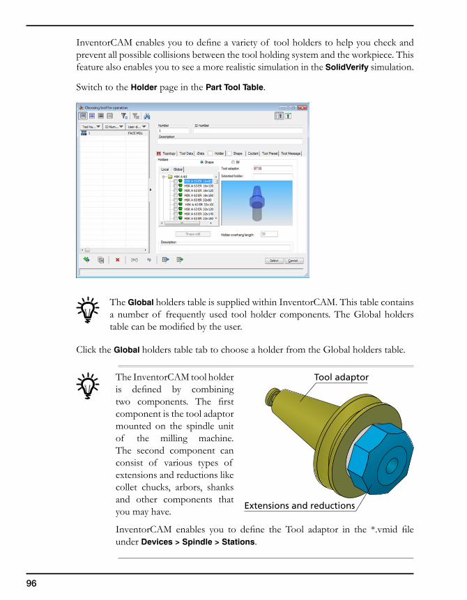
96
InventorCAM enables you to define a variety of tool holders to help you check and prevent all possible collisions between the tool holding system and the workpiece. This feature also enables you to see a more realistic simulation in the SolidVerify simulation.
Switch to the Holder page in the Part Tool Table.
The Global holders table is supplied within InventorCAM. This table contains a number of frequently used tool holder components. The Global holders table can be modified by the user.
Click the Global holders table tab to choose a holder from the Global holders table.
The InventorCAM tool holder is defined by combining two components. The first component is the tool adaptor mounted on the spindle unit of the milling machine. The second component can consist of various types of extensions and reductions like collet chucks, arbors, shanks and other components that you may have.
InventorCAM enables you to define the Tool adaptor in the *.vmid file under Devices > Spindle > Stations.
Tool adaptor
Extensions and reductions

97
3. InventorCAM 2.5D Operations
In the Global holder table, choose the BT40 ER32×60 collet chuck. This collet chuck is suitable for the chosen tool diameter (40 mm).
Choose the defined tool for the operation by clicking the Select button. The Face Milling Operation dialog box is displayed.
12. Define the Face depth
Switch to the Levels page of the Face Milling Operation dialog box. Click the Face depth button in the Milling levels area and select the model face as shown.
The Face depth (2) is calculated.
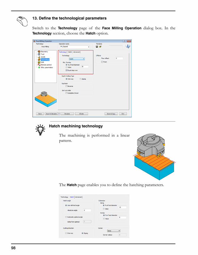
98
13. Define the technological parameters
Switch to the Technology page of the Face Milling Operation dialog box. In the Technology section, choose the Hatch option.
Hatch machining technology
The machining is performed in a linear pattern.
The Hatch page enables you to define the hatching parameters.
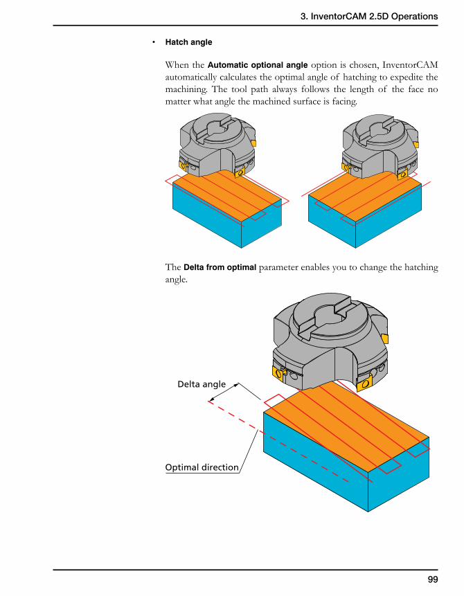
99
3. InventorCAM 2.5D Operations
• Hatchangle
When the Automatic optional angle option is chosen, InventorCAM automatically calculates the optimal angle of hatching to expedite the machining. The tool path always follows the length of the face no matter what angle the machined surface is facing.
The Delta from optimal parameter enables you to change the hatching angle.
Optimal direction
Delta angle
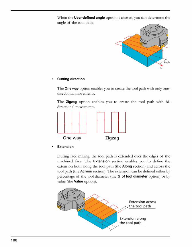
100
Extension alongthe tool path
Extension acrossthe tool path
When the User-defined angle option is chosen, you can determine the angle of the tool path.
• Cuttingdirection
The One way option enables you to create the tool path with only one-directional movements.
The Zigzag option enables you to create the tool path with bi-directional movements.
• Extension
During face milling, the tool path is extended over the edges of the machined face. The Extension section enables you to define the extension both along the tool path (the Along section) and across the tool path (the Across section). The extension can be defined either by percentage of the tool diameter (the % of tool diameter option) or by value (the Value option).
X
Angle
ZigzagOne way
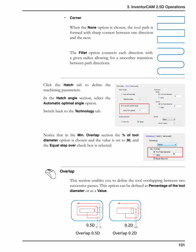
101
3. InventorCAM 2.5D Operations
• Corner
When the None option is chosen, the tool path is formed with sharp corners between one direction and the next.
The Fillet option connects each direction with a given radius allowing for a smoother transition between path directions.
Click the Hatch tab to define the machining parameters.
In the Hatch angle section, select the Automatic optimal angle option.
Switch back to the Technology tab.
Notice that in the Min. Overlap section the % of tool diameter option is chosen and the value is set to 30, and the Equal step over check box is selected.
Overlap
This section enables you to define the tool overlapping between two successive passes. This option can be defined as Percentage of the tool diameter or as a Value.
0.5D
Overlap 0.5D
0.2D
Overlap 0.2D
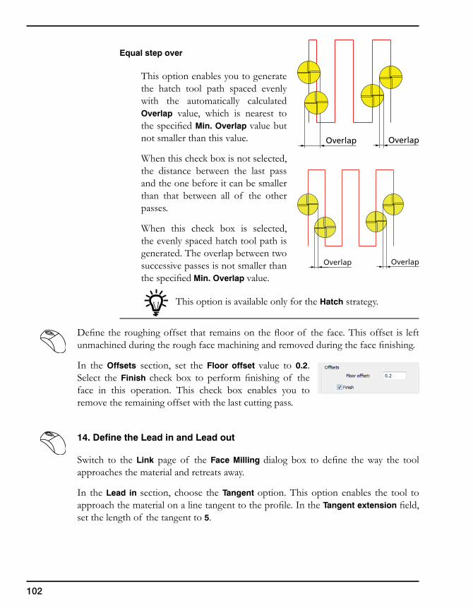
102
Equal step over
This option enables you to generate the hatch tool path spaced evenly with the automatically calculated Overlap value, which is nearest to the specified Min. Overlap value but not smaller than this value.
When this check box is not selected, the distance between the last pass and the one before it can be smaller than that between all of the other passes.
When this check box is selected, the evenly spaced hatch tool path is generated. The overlap between two successive passes is not smaller than the specified Min. Overlap value.
This option is available only for the Hatch strategy.
Define the roughing offset that remains on the floor of the face. This offset is left unmachined during the rough face machining and removed during the face finishing.
In the Offsets section, set the Floor offset value to 0.2. Select the Finish check box to perform finishing of the face in this operation. This check box enables you to remove the remaining offset with the last cutting pass.
14. Define the Lead in and Lead out
Switch to the Link page of the Face Milling dialog box to define the way the tool approaches the material and retreats away.
In the Lead in section, choose the Tangent option. This option enables the tool to approach the material on a line tangent to the profile. In the Tangent extension field, set the length of the tangent to 5.
OverlapOverlap
OverlapOverlap
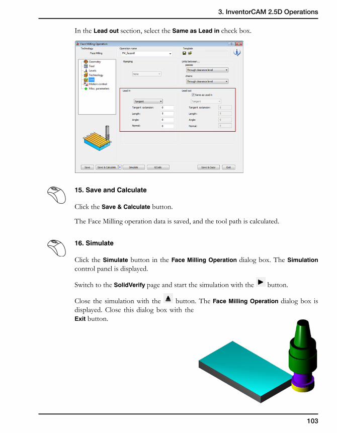
103
3. InventorCAM 2.5D Operations
In the Lead out section, select the Same as Lead in check box.
15. Save and Calculate
Click the Save & Calculate button.
The Face Milling operation data is saved, and the tool path is calculated.
16. Simulate
Click the Simulate button in the Face Milling Operation dialog box. The Simulation control panel is displayed.
Switch to the SolidVerify page and start the simulation with the button.
Close the simulation with the button. The Face Milling Operation dialog box is displayed. Close this dialog box with the Exit button.
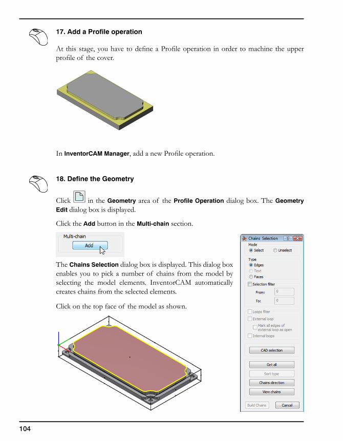
104
17. Add a Profile operation
At this stage, you have to define a Profile operation in order to machine the upper profile of the cover.
In InventorCAM Manager, add a new Profile operation.
18. Define the Geometry
Click in the Geometry area of the Profile Operation dialog box. The Geometry Edit dialog box is displayed.
Click the Add button in the Multi-chain section.
The Chains Selection dialog box is displayed. This dialog box enables you to pick a number of chains from the model by selecting the model elements. InventorCAM automatically creates chains from the selected elements.
Click on the top face of the model as shown.
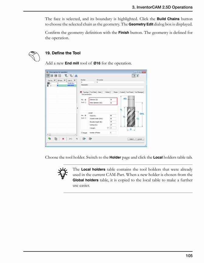
105
3. InventorCAM 2.5D Operations
The face is selected, and its boundary is highlighted. Click the Build Chains button to choose the selected chain as the geometry. The Geometry Edit dialog box is displayed.
Confirm the geometry definition with the Finish button. The geometry is defined for the operation.
19. Define the Tool
Add a new End mill tool of Ø16 for the operation.
Choose the tool holder. Switch to the Holder page and click the Local holders table tab.
The Local holders table contains the tool holders that were already used in the current CAM-Part. When a new holder is chosen from the Global holders table, it is copied to the local table to make a further use easier.
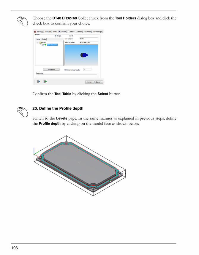
106
Choose the BT40 ER32×60 Collet chuck from the Tool Holders dialog box and click the check box to confirm your choice.
Confirm the Tool Table by clicking the Select button.
20. Define the Profile depth
Switch to the Levels page. In the same manner as explained in previous steps, define the Profile depth by clicking on the model face as shown below.
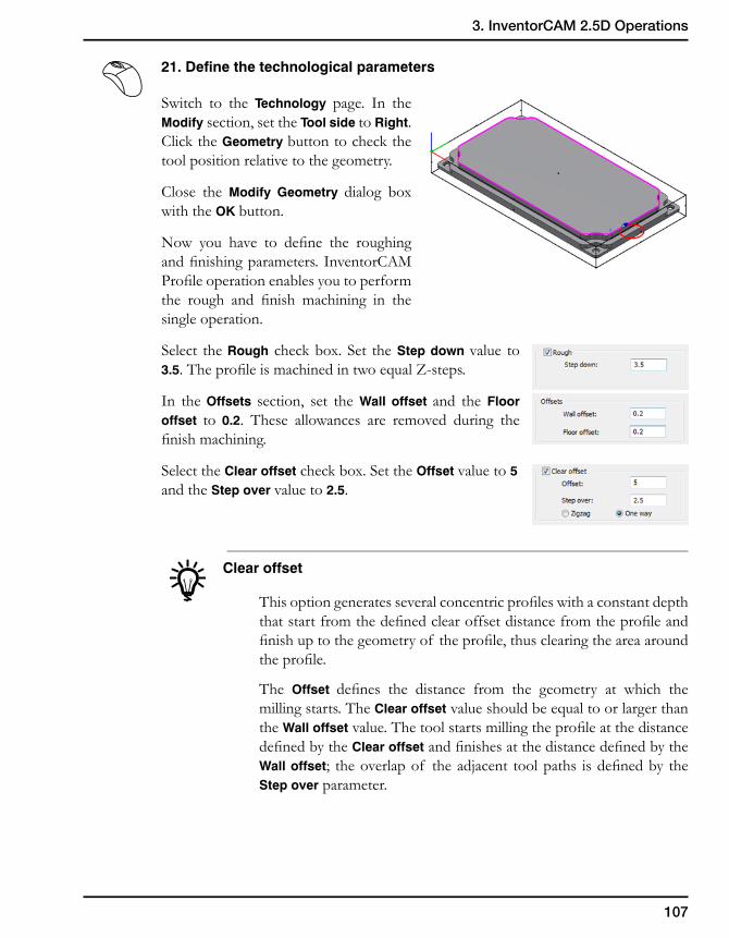
107
3. InventorCAM 2.5D Operations
21. Define the technological parameters
Switch to the Technology page. In the Modify section, set the Tool side to Right. Click the Geometry button to check the tool position relative to the geometry.
Close the Modify Geometry dialog box with the OK button.
Now you have to define the roughing and finishing parameters. InventorCAM Profile operation enables you to perform the rough and finish machining in the single operation.
Select the Rough check box. Set the Step down value to 3.5. The profile is machined in two equal Z-steps.
In the Offsets section, set the Wall offset and the Floor offset to 0.2. These allowances are removed during the finish machining.
Select the Clear offset check box. Set the Offset value to 5 and the Step over value to 2.5.
Clear offset
This option generates several concentric profiles with a constant depth that start from the defined clear offset distance from the profile and finish up to the geometry of the profile, thus clearing the area around the profile.
The Offset defines the distance from the geometry at which the milling starts. The Clear offset value should be equal to or larger than the Wall offset value. The tool starts milling the profile at the distance defined by the Clear offset and finishes at the distance defined by the Wall offset; the overlap of the adjacent tool paths is defined by the Step over parameter.
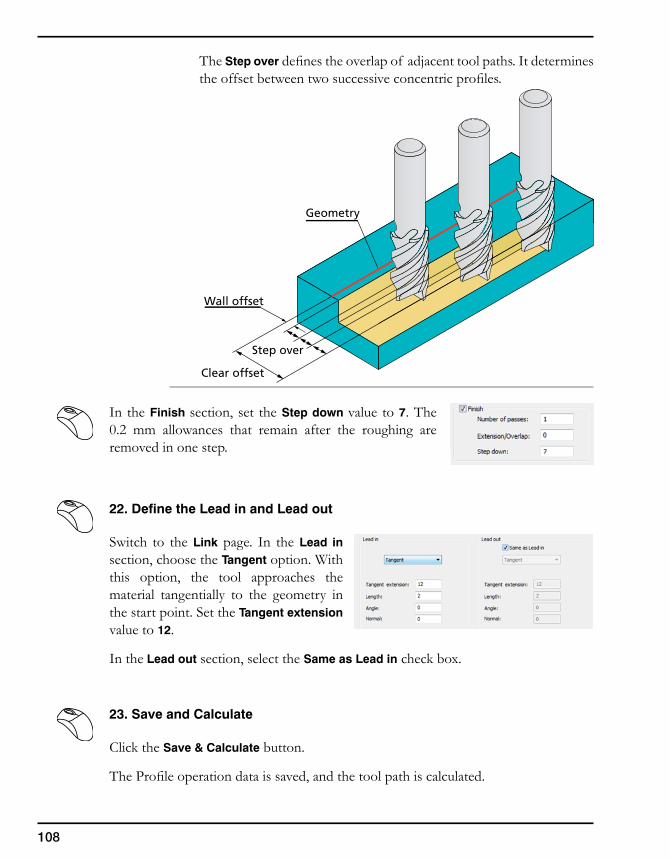
108
The Step over defines the overlap of adjacent tool paths. It determines the offset between two successive concentric profiles.
In the Finish section, set the Step down value to 7. The 0.2 mm allowances that remain after the roughing are removed in one step.
22. Define the Lead in and Lead out
Switch to the Link page. In the Lead in section, choose the Tangent option. With this option, the tool approaches the material tangentially to the geometry in the start point. Set the Tangent extension value to 12.
In the Lead out section, select the Same as Lead in check box.
23. Save and Calculate
Click the Save & Calculate button.
The Profile operation data is saved, and the tool path is calculated.
Wall offset
Step over
Geometry
Clear offset
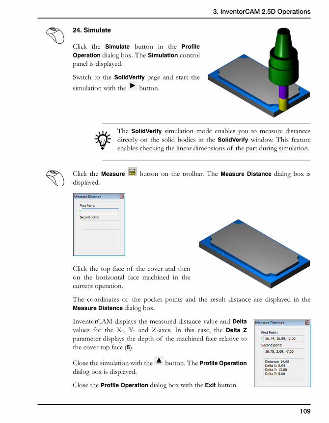
109
3. InventorCAM 2.5D Operations
24. Simulate
Click the Simulate button in the Profile Operation dialog box. The Simulation control panel is displayed.
Switch to the SolidVerify page and start the simulation with the button.
The SolidVerify simulation mode enables you to measure distances directly on the solid bodies in the SolidVerify window. This feature enables checking the linear dimensions of the part during simulation.
Click the Measure button on the toolbar. The Measure Distance dialog box is displayed.
Click the top face of the cover and then on the horizontal face machined in the current operation.
The coordinates of the pocket points and the result distance are displayed in the Measure Distance dialog box.
InventorCAM displays the measured distance value and Delta values for the X-, Y- and Z-axes. In this case, the Delta Z parameter displays the depth of the machined face relative to the cover top face (5).
Close the simulation with the button. The Profile Operation dialog box is displayed.
Close the Profile Operation dialog box with the Exit button.
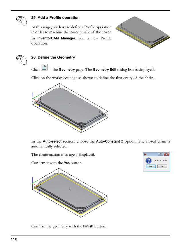
110
25. Add a Profile operation
At this stage, you have to define a Profile operation in order to machine the lower profile of the cover.In InventorCAM Manager, add a new Profile operation.
26. Define the Geometry
Click in the Geometry page. The Geometry Edit dialog box is displayed.
Click on the workpiece edge as shown to define the first entity of the chain.
In the Auto-select section, choose the Auto-Constant Z option. The closed chain is automatically selected.
The confirmation message is displayed.
Confirm it with the Yes button.
Confirm the geometry with the Finish button.
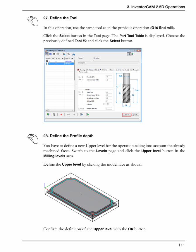
111
3. InventorCAM 2.5D Operations
27. Define the Tool
In this operation, use the same tool as in the previous operation (Ø16 End mill).
Click the Select button in the Tool page. The Part Tool Table is displayed. Choose the previously defined Tool #2 and click the Select button.
28. Define the Profile depth
You have to define a new Upper level for the operation taking into account the already machined faces. Switch to the Levels page and click the Upper level button in the Milling levels area.
Define the Upper level by clicking the model face as shown.
Confirm the definition of the Upper level with the OK button.
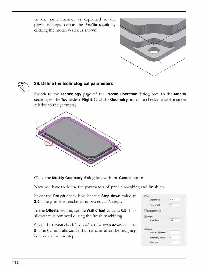
112
In the same manner as explained in the previous steps, define the Profile depth by clicking the model vertex as shown.
29. Define the technological parameters
Switch to the Technology page of the Profile Operation dialog box. In the Modify section, set the Tool side to Right. Click the Geometry button to check the tool position relative to the geometry.
Close the Modify Geometry dialog box with the Cancel button.
Now you have to define the parameters of profile roughing and finishing.
Select the Rough check box. Set the Step down value to 2.5. The profile is machined in two equal Z-steps.
In the Offsets section, set the Wall offset value to 0.5. This allowance is removed during the finish machining.
Select the Finish check box and set the Step down value to 5. The 0.5 mm allowance that remains after the roughing is removed in one step.
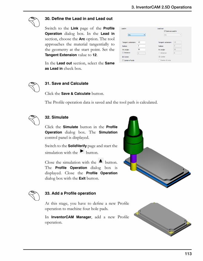
113
3. InventorCAM 2.5D Operations
30. Define the Lead in and Lead out
Switch to the Link page of the Profile Operation dialog box. In the Lead in section, choose the Arc option. The tool approaches the material tangentially to the geometry at the start point. Set the Tangent Extension value to 12.
In the Lead out section, select the Same as Lead in check box.
31. Save and Calculate
Click the Save & Calculate button.
The Profile operation data is saved and the tool path is calculated.
32. Simulate
Click the Simulate button in the Profile Operation dialog box. The Simulation control panel is displayed.
Switch to the SolidVerify page and start the simulation with the button.
Close the simulation with the button. The Profile Operation dialog box is displayed. Close the Profile Operation dialog box with the Exit button.
33. Add a Profile operation
At this stage, you have to define a new Profile operation to machine four hole pads.
In InventorCAM Manager, add a new Profile operation.
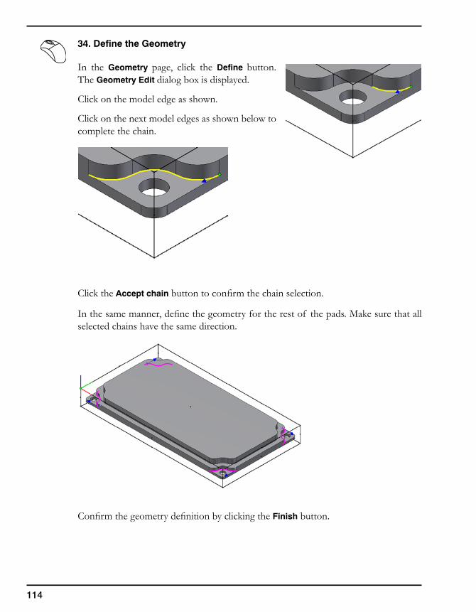
114
34. Define the Geometry
In the Geometry page, click the Define button. The Geometry Edit dialog box is displayed.
Click on the model edge as shown.
Click on the next model edges as shown below to complete the chain.
Click the Accept chain button to confirm the chain selection.
In the same manner, define the geometry for the rest of the pads. Make sure that all selected chains have the same direction.
Confirm the geometry definition by clicking the Finish button.
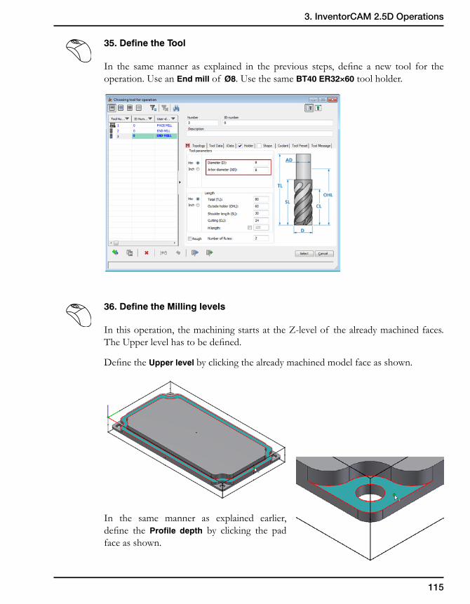
115
3. InventorCAM 2.5D Operations
35. Define the Tool
In the same manner as explained in the previous steps, define a new tool for the operation. Use an End mill of Ø8. Use the same BT40 ER32×60 tool holder.
36. Define the Milling levels
In this operation, the machining starts at the Z-level of the already machined faces. The Upper level has to be defined.
Define the Upper level by clicking the already machined model face as shown.
In the same manner as explained earlier, define the Profile depth by clicking the pad face as shown.
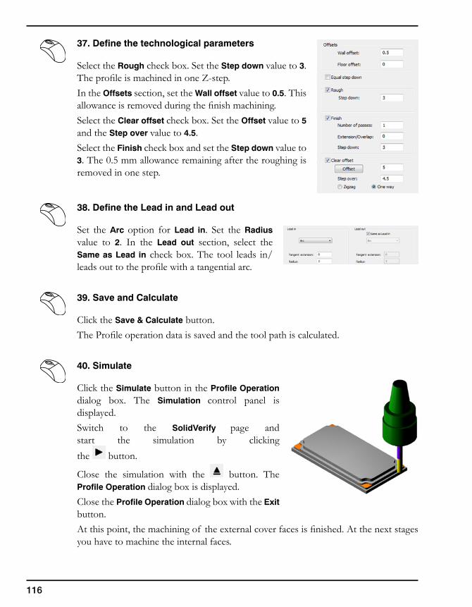
116
37. Define the technological parameters
Select the Rough check box. Set the Step down value to 3. The profile is machined in one Z-step.In the Offsets section, set the Wall offset value to 0.5. This allowance is removed during the finish machining.Select the Clear offset check box. Set the Offset value to 5 and the Step over value to 4.5.Select the Finish check box and set the Step down value to 3. The 0.5 mm allowance remaining after the roughing is removed in one step.
38. Define the Lead in and Lead out
Set the Arc option for Lead in. Set the Radius value to 2. In the Lead out section, select the Same as Lead in check box. The tool leads in/leads out to the profile with a tangential arc.
39. Save and Calculate
Click the Save & Calculate button.The Profile operation data is saved and the tool path is calculated.
40. Simulate
Click the Simulate button in the Profile Operation dialog box. The Simulation control panel is displayed.Switch to the SolidVerify page and start the simulation by clicking the button.
Close the simulation with the button. The Profile Operation dialog box is displayed.Close the Profile Operation dialog box with the Exit button.At this point, the machining of the external cover faces is finished. At the next stages you have to machine the internal faces.
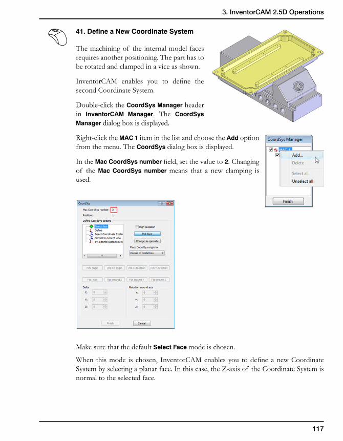
117
3. InventorCAM 2.5D Operations
41. Define a New Coordinate System
The machining of the internal model faces requires another positioning. The part has to be rotated and clamped in a vice as shown.
InventorCAM enables you to define the second Coordinate System.
Double-click the CoordSys Manager header in InventorCAM Manager. The CoordSys Manager dialog box is displayed.
Right-click the MAC 1 item in the list and choose the Add option from the menu. The CoordSys dialog box is displayed.
In the Mac CoordSys number field, set the value to 2. Changing of the Mac CoordSys number means that a new clamping is used.
Make sure that the default Select Face mode is chosen.
When this mode is chosen, InventorCAM enables you to define a new Coordinate System by selecting a planar face. In this case, the Z-axis of the Coordinate System is normal to the selected face.
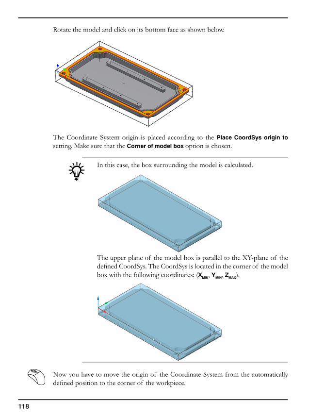
118
Rotate the model and click on its bottom face as shown below.
The Coordinate System origin is placed according to the Place CoordSys origin to setting. Make sure that the Corner of model box option is chosen.
In this case, the box surrounding the model is calculated.
The upper plane of the model box is parallel to the XY-plane of the defined CoordSys. The CoordSys is located in the corner of the model box with the following coordinates: (XMIN, YMIN, ZMAX).
Now you have to move the origin of the Coordinate System from the automatically defined position to the corner of the workpiece.
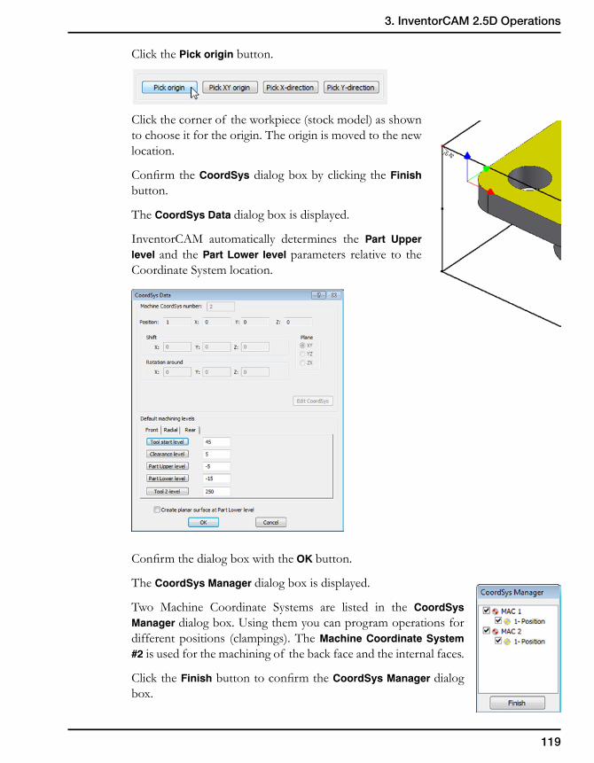
119
3. InventorCAM 2.5D Operations
Click the Pick origin button.
Click the corner of the workpiece (stock model) as shown to choose it for the origin. The origin is moved to the new location.
Confirm the CoordSys dialog box by clicking the Finish button.
The CoordSys Data dialog box is displayed.
InventorCAM automatically determines the Part Upper level and the Part Lower level parameters relative to the Coordinate System location.
Confirm the dialog box with the OK button.
The CoordSys Manager dialog box is displayed.
Two Machine Coordinate Systems are listed in the CoordSys Manager dialog box. Using them you can program operations for different positions (clampings). The Machine Coordinate System #2 is used for the machining of the back face and the internal faces.
Click the Finish button to confirm the CoordSys Manager dialog box.
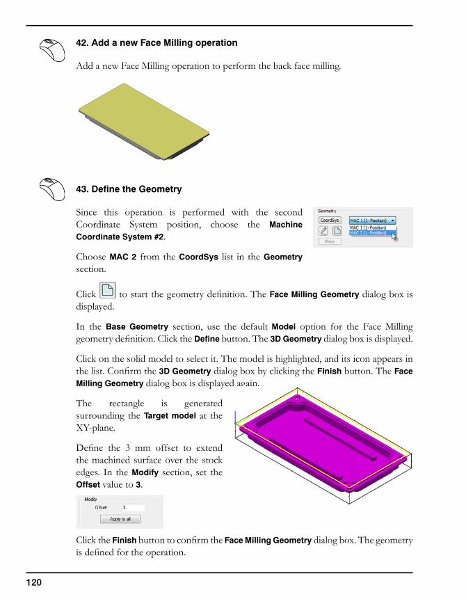
120
42. Add a new Face Milling operation
Add a new Face Milling operation to perform the back face milling.
43. Define the Geometry
Since this operation is performed with the second Coordinate System position, choose the Machine Coordinate System #2.
Choose MAC 2 from the CoordSys list in the Geometry section.
Click to start the geometry definition. The Face Milling Geometry dialog box is displayed.
In the Base Geometry section, use the default Model option for the Face Milling geometry definition. Click the Define button. The 3D Geometry dialog box is displayed.
Click on the solid model to select it. The model is highlighted, and its icon appears in the list. Confirm the 3D Geometry dialog box by clicking the Finish button. The Face Milling Geometry dialog box is displayed again.
The rectangle is generated surrounding the Target model at the XY-plane.
Define the 3 mm offset to extend the machined surface over the stock edges. In the Modify section, set the Offset value to 3.
Click the Finish button to confirm the Face Milling Geometry dialog box. The geometry is defined for the operation.
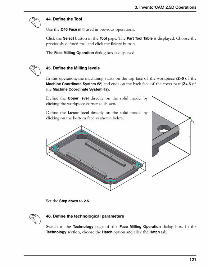
121
3. InventorCAM 2.5D Operations
44. Define the Tool
Use the Ø40 Face mill used in previous operations.
Click the Select button in the Tool page. The Part Tool Table is displayed. Choose the previously defined tool and click the Select button.
The Face Milling Operation dialog box is displayed.
45. Define the Milling levels
In this operation, the machining starts on the top face of the workpiece (Z=0 of the Machine Coordinate System #2) and ends on the back face of the cover part (Z=-5 of the Machine Coordinate System #2).
Define the Upper level directly on the solid model by clicking the workpiece corner as shown.
Define the Lower level directly on the solid model by clicking on the bottom face as shown below.
Set the Step down to 2.5.
46. Define the technological parameters
Switch to the Technology page of the Face Milling Operation dialog box. In the Technology section, choose the Hatch option and click the Hatch tab.
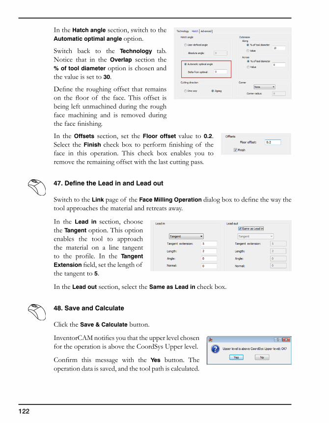
122
In the Hatch angle section, switch to the Automatic optimal angle option.
Switch back to the Technology tab. Notice that in the Overlap section the % of tool diameter option is chosen and the value is set to 30.
Define the roughing offset that remains on the floor of the face. This offset is being left unmachined during the rough face machining and is removed during the face finishing.
In the Offsets section, set the Floor offset value to 0.2. Select the Finish check box to perform finishing of the face in this operation. This check box enables you to remove the remaining offset with the last cutting pass.
47. Define the Lead in and Lead out
Switch to the Link page of the Face Milling Operation dialog box to define the way the tool approaches the material and retreats away.
In the Lead in section, choose the Tangent option. This option enables the tool to approach the material on a line tangent to the profile. In the Tangent Extension field, set the length of the tangent to 5.
In the Lead out section, select the Same as Lead in check box.
48. Save and Calculate
Click the Save & Calculate button.
InventorCAM notifies you that the upper level chosen for the operation is above the CoordSys Upper level.
Confirm this message with the Yes button. The operation data is saved, and the tool path is calculated.
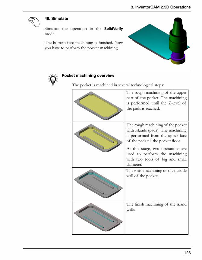
123
3. InventorCAM 2.5D Operations
49. Simulate
Simulate the operation in the SolidVerify mode.
The bottom face machining is finished. Now you have to perform the pocket machining.
Pocket machining overview
The pocket is machined in several technological steps:
The rough machining of the upper part of the pocket. The machining is performed until the Z-level of the pads is reached.
The rough machining of the pocket with islands (pads). The machining is performed from the upper face of the pads till the pocket floor.
At this stage, two operations are used to perform the machining with two tools of big and small diameter.The finish machining of the outside wall of the pocket.
The finish machining of the island walls.
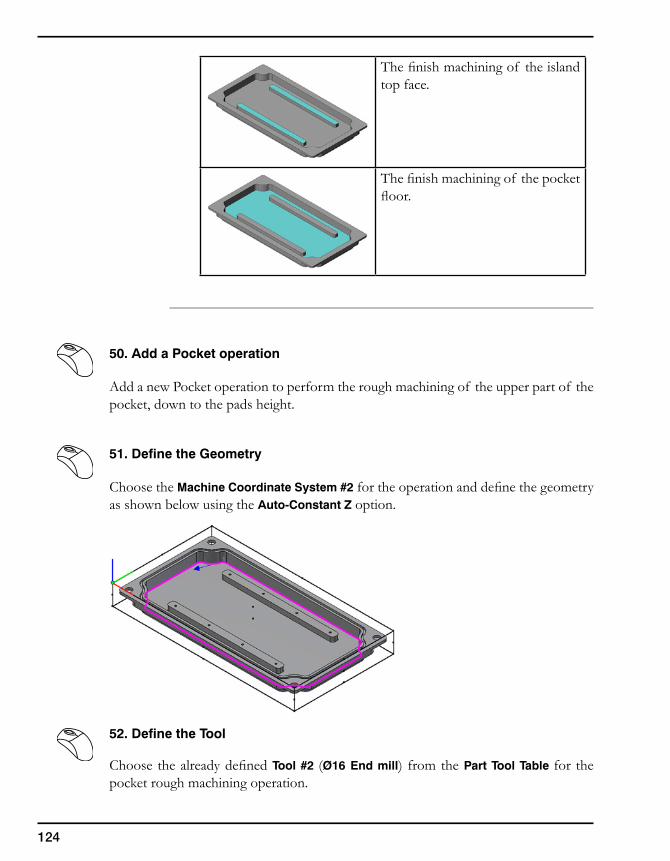
124
The finish machining of the island top face.
The finish machining of the pocket floor.
50. Add a Pocket operation
Add a new Pocket operation to perform the rough machining of the upper part of the pocket, down to the pads height.
51. Define the Geometry
Choose the Machine Coordinate System #2 for the operation and define the geometry as shown below using the Auto-Constant Z option.
52. Define the Tool
Choose the already defined Tool #2 (Ø16 End mill) from the Part Tool Table for the pocket rough machining operation.
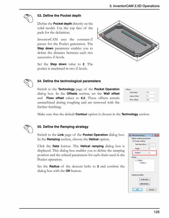
125
3. InventorCAM 2.5D Operations
53. Define the Pocket depth
Define the Pocket depth directly on the solid model. Use the top face of the pads for the definition.
InventorCAM uses the constant-Z passes for the Pocket generation. The Step down parameter enables you to define the distance between each two successive Z-levels.
Set the Step down value to 2. The pocket is machined in two Z-levels.
54. Define the technological parameters
Switch to the Technology page of the Pocket Operation dialog box. In the Offsets section, set the Wall offset and Floor offset values to 0.2. These offsets remain unmachined during roughing and are removed with the further finishing.
Make sure that the default Contour option is chosen in the Technology section.
55. Define the Ramping strategy
Switch to the Link page of the Pocket Operation dialog box. In the Ramping section, choose the Helical option.
Click the Data button. The Helical ramping dialog box is displayed. This dialog box enables you to define the ramping position and the related parameters for each chain used in the Pocket operation.
Set the Radius of the descent helix to 3 and confirm the dialog box with the OK button.
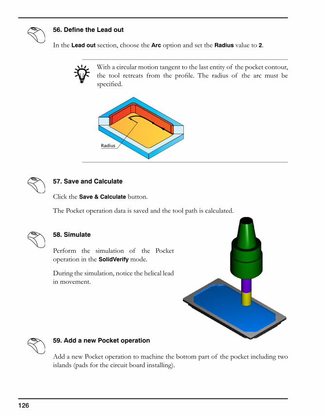
126
56. Define the Lead out
In the Lead out section, choose the Arc option and set the Radius value to 2.
With a circular motion tangent to the last entity of the pocket contour, the tool retreats from the profile. The radius of the arc must be specified.
57. Save and Calculate
Click the Save & Calculate button.
The Pocket operation data is saved and the tool path is calculated.
58. Simulate
Perform the simulation of the Pocket operation in the SolidVerify mode.
During the simulation, notice the helical lead in movement.
59. Add a new Pocket operation
Add a new Pocket operation to machine the bottom part of the pocket including two islands (pads for the circuit board installing).
Radius
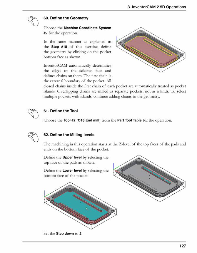
127
3. InventorCAM 2.5D Operations
60. Define the Geometry
Choose the Machine Coordinate System #2 for the operation.
In the same manner as explained in the Step #18 of this exercise, define the geometry by clicking on the pocket bottom face as shown.
InventorCAM automatically determines the edges of the selected face and defines chains on them. The first chain is the external boundary of the pocket. All closed chains inside the first chain of each pocket are automatically treated as pocket islands. Overlapping chains are milled as separate pockets, not as islands. To select multiple pockets with islands, continue adding chains to the geometry.
61. Define the Tool
Choose the Tool #2 (Ø16 End mill) from the Part Tool Table for the operation.
62. Define the Milling levels
The machining in this operation starts at the Z-level of the top faces of the pads and ends on the bottom face of the pocket.
Define the Upper level by selecting the top face of the pads as shown.
Define the Lower level by selecting the bottom face of the pocket.
Set the Step down to 2.
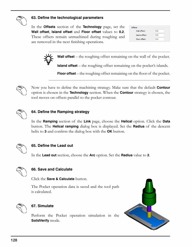
128
63. Define the technological parameters
In the Offsets section of the Technology page, set the Wall offset, Island offset and Floor offset values to 0.2. These offsets remain unmachined during roughing and are removed in the next finishing operations.
Wall offset – the roughing offset remaining on the wall of the pocket.
Island offset – the roughing offset remaining on the pocket’s islands.
Floor offset – the roughing offset remaining on the floor of the pocket.
Now you have to define the machining strategy. Make sure that the default Contour option is chosen in the Technology section. When the Contour strategy is chosen, the tool moves on offsets parallel to the pocket contour.
64. Define the Ramping strategy
In the Ramping section of the Link page, choose the Helical option. Click the Data button. The Helical ramping dialog box is displayed. Set the Radius of the descent helix to 3 and confirm the dialog box with the OK button.
65. Define the Lead out
In the Lead out section, choose the Arc option. Set the Radius value to 2.
66. Save and Calculate
Click the Save & Calculate button.
The Pocket operation data is saved and the tool path is calculated.
67. Simulate
Perform the Pocket operation simulation in the SolidVerify mode.
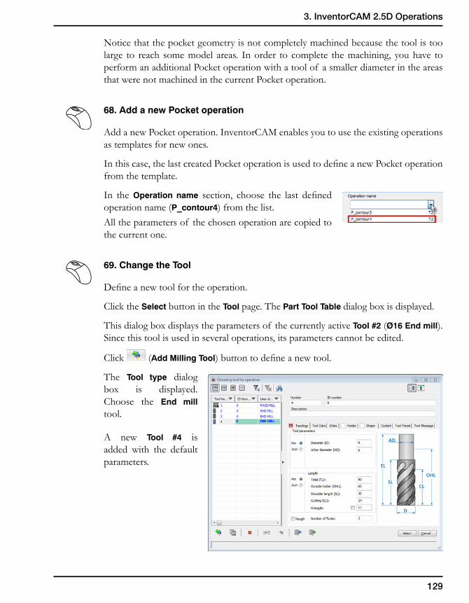
129
3. InventorCAM 2.5D Operations
Notice that the pocket geometry is not completely machined because the tool is too large to reach some model areas. In order to complete the machining, you have to perform an additional Pocket operation with a tool of a smaller diameter in the areas that were not machined in the current Pocket operation.
68. Add a new Pocket operation
Add a new Pocket operation. InventorCAM enables you to use the existing operations as templates for new ones.
In this case, the last created Pocket operation is used to define a new Pocket operation from the template.
In the Operation name section, choose the last defined operation name (P_contour4) from the list.All the parameters of the chosen operation are copied to the current one.
69. Change the Tool
Define a new tool for the operation.
Click the Select button in the Tool page. The Part Tool Table dialog box is displayed.
This dialog box displays the parameters of the currently active Tool #2 (Ø16 End mill). Since this tool is used in several operations, its parameters cannot be edited.
Click (Add Milling Tool) button to define a new tool.
The Tool type dialog box is displayed. Choose the End mill tool.
A new Tool #4 is added with the default parameters.
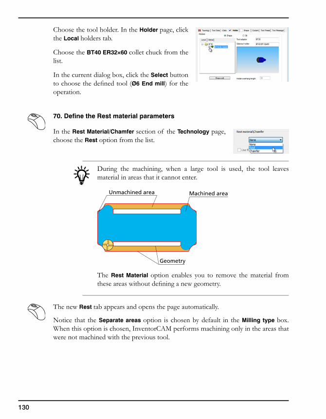
130
Choose the tool holder. In the Holder page, click the Local holders tab.
Choose the BT40 ER32×60 collet chuck from the list.
In the current dialog box, click the Select button to choose the defined tool (Ø6 End mill) for the operation.
70. Define the Rest material parameters
In the Rest Material/Chamfer section of the Technology page, choose the Rest option from the list.
During the machining, when a large tool is used, the tool leaves material in areas that it cannot enter.
The Rest Material option enables you to remove the material from these areas without defining a new geometry.
The new Rest tab appears and opens the page automatically.
Notice that the Separate areas option is chosen by default in the Milling type box. When this option is chosen, InventorCAM performs machining only in the areas that were not machined with the previous tool.
Machined area
Geometry
Unmachined area
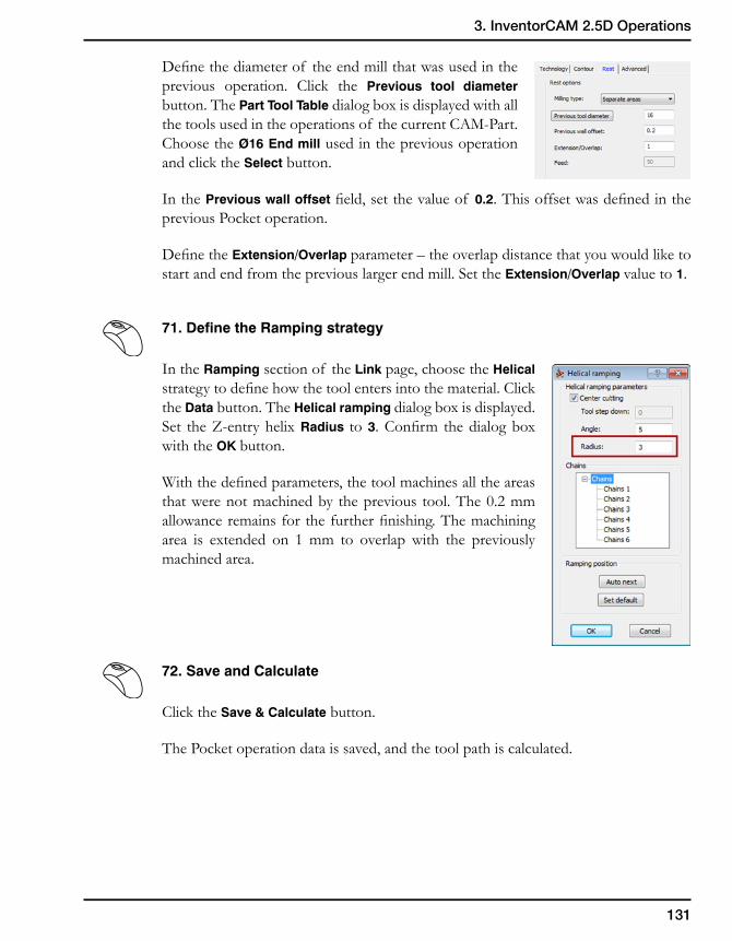
131
3. InventorCAM 2.5D Operations
Define the diameter of the end mill that was used in the previous operation. Click the Previous tool diameter button. The Part Tool Table dialog box is displayed with all the tools used in the operations of the current CAM-Part. Choose the Ø16 End mill used in the previous operation and click the Select button.
In the Previous wall offset field, set the value of 0.2. This offset was defined in the previous Pocket operation.
Define the Extension/Overlap parameter – the overlap distance that you would like to start and end from the previous larger end mill. Set the Extension/Overlap value to 1.
71. Define the Ramping strategy
In the Ramping section of the Link page, choose the Helical strategy to define how the tool enters into the material. Click the Data button. The Helical ramping dialog box is displayed. Set the Z-entry helix Radius to 3. Confirm the dialog box with the OK button.
With the defined parameters, the tool machines all the areas that were not machined by the previous tool. The 0.2 mm allowance remains for the further finishing. The machining area is extended on 1 mm to overlap with the previously machined area.
72. Save and Calculate
Click the Save & Calculate button.
The Pocket operation data is saved, and the tool path is calculated.
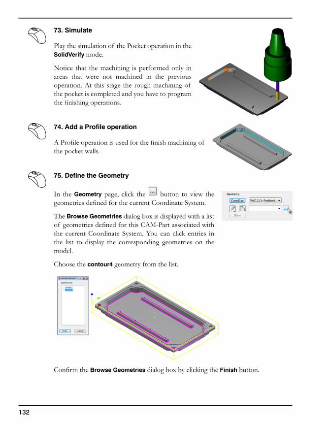
132
73. Simulate
Play the simulation of the Pocket operation in the SolidVerify mode.
Notice that the machining is performed only in areas that were not machined in the previous operation. At this stage the rough machining of the pocket is completed and you have to program the finishing operations.
74. Add a Profile operation
A Profile operation is used for the finish machining of the pocket walls.
75. Define the Geometry
In the Geometry page, click the button to view the geometries defined for the current Coordinate System.
The Browse Geometries dialog box is displayed with a list of geometries defined for this CAM-Part associated with the current Coordinate System. You can click entries in the list to display the corresponding geometries on the model.
Choose the contour4 geometry from the list.
Confirm the Browse Geometries dialog box by clicking the Finish button.
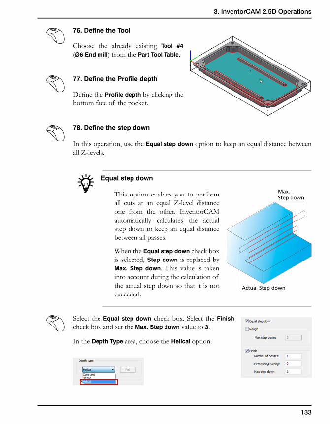
133
3. InventorCAM 2.5D Operations
76. Define the Tool
Choose the already existing Tool #4 (Ø6 End mill) from the Part Tool Table.
77. Define the Profile depth
Define the Profile depth by clicking the bottom face of the pocket.
78. Define the step down
In this operation, use the Equal step down option to keep an equal distance between all Z-levels.
Equal step down
This option enables you to perform all cuts at an equal Z-level distance one from the other. InventorCAM automatically calculates the actual step down to keep an equal distance between all passes.
When the Equal step down check box is selected, Step down is replaced by Max. Step down. This value is taken into account during the calculation of the actual step down so that it is not exceeded.
Select the Equal step down check box. Select the Finish check box and set the Max. Step down value to 3.
In the Depth Type area, choose the Helical option.
Max.Step down
Actual Step down
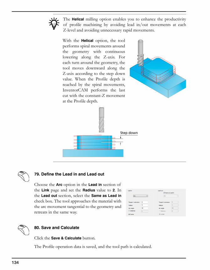
134
The Helical milling option enables you to enhance the productivity of profile machining by avoiding lead in/out movements at each Z-level and avoiding unnecessary rapid movements.
With the Helical option, the tool performs spiral movements around the geometry with continuous lowering along the Z-axis. For each turn around the geometry, the tool moves downward along the Z-axis according to the step down value. When the Profile depth is reached by the spiral movements, InventorCAM performs the last cut with the constant-Z movement at the Profile depth.
79. Define the Lead in and Lead out
Choose the Arc option in the Lead in section of the Link page and set the Radius value to 2. In the Lead out section, select the Same as Lead in check box. The tool approaches the material with the arc movement tangential to the geometry and retreats in the same way.
80. Save and Calculate
Click the Save & Calculate button.
The Profile operation data is saved, and the tool path is calculated.
Step down
135
3. InventorCAM 2.5D Operations
81. Simulate
Play the simulation in the SolidVerify mode.
82. Add a Profile operation
Add a new Profile operation to machine the walls of the islands.
83. Define the Geometry
Choose the Machine Coordinate System #2 for the operation and click in the Geometry page. The Geometry Edit dialog box is displayed.
Select the edge of the island as shown below.
Make sure that the chain direction is clockwise. Such direction enables you to perform the climb milling of the profile.In the Auto-select section, choose the Auto-constant Z option. The chain is automatically completed.
136
The confirmation message is displayed.
Confirm it by clicking the Yes button. The first chain is defined.
Select the edge of the other island as shown below.
Make sure that the chain direction is clockwise. Such direction enables you to perform the climb milling of the profile.
In the Auto-select section, choose the Auto-constant Z option. The chain is automatically completed and the confirmation message is displayed. Confirm it by clicking the Yes button.
The first selected entity in the geometry chain defines the approach location for the whole chain. In this case, the internal edges of the pads are chosen in order to prevent the collision between the tool and pocket wall during the lead in movement.
Confirm the Geometry definition with the Finish button.
84. Define the Tool
Choose the Tool #4 (Ø6 End mill) for the operation.
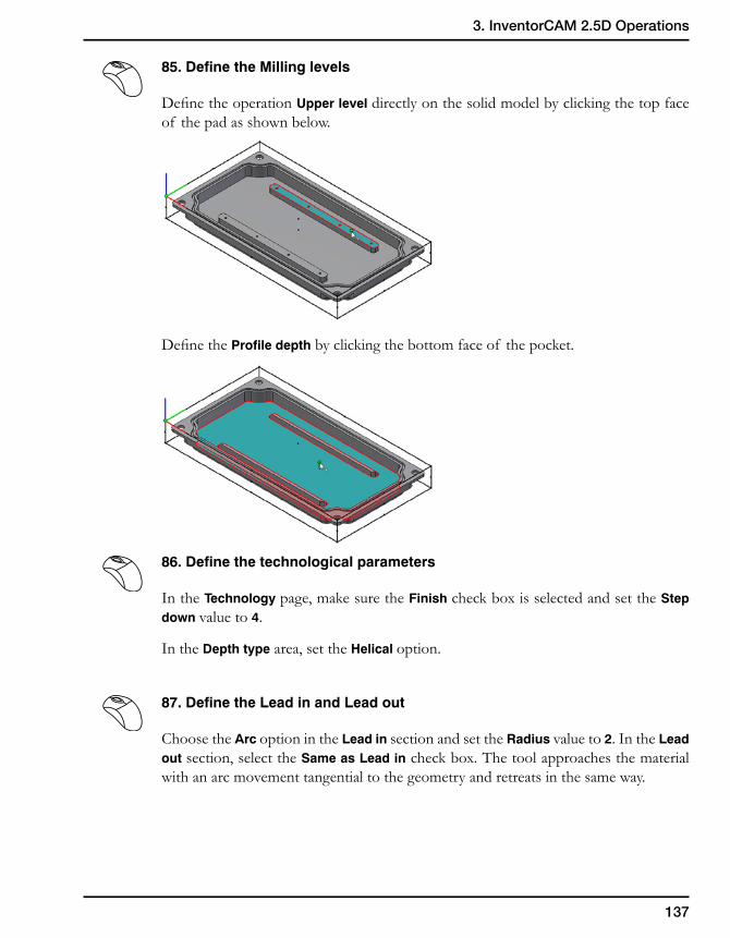
137
3. InventorCAM 2.5D Operations
85. Define the Milling levels
Define the operation Upper level directly on the solid model by clicking the top face of the pad as shown below.
Define the Profile depth by clicking the bottom face of the pocket.
86. Define the technological parameters
In the Technology page, make sure the Finish check box is selected and set the Step down value to 4.
In the Depth type area, set the Helical option.
87. Define the Lead in and Lead out
Choose the Arc option in the Lead in section and set the Radius value to 2. In the Lead out section, select the Same as Lead in check box. The tool approaches the material with an arc movement tangential to the geometry and retreats in the same way.
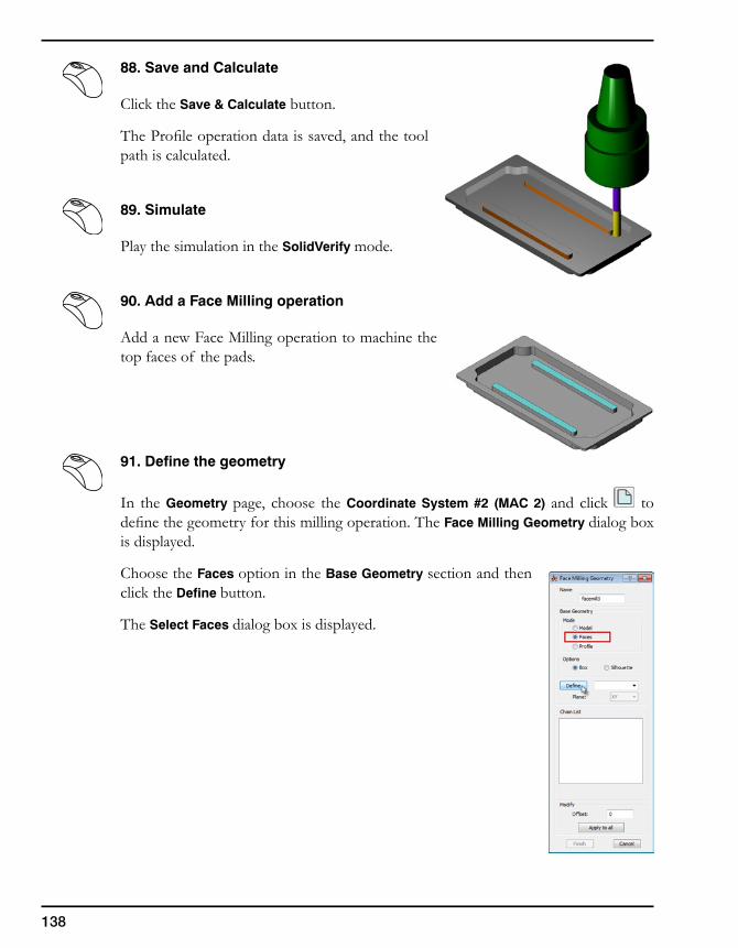
138
88. Save and Calculate
Click the Save & Calculate button.
The Profile operation data is saved, and the tool path is calculated.
89. Simulate
Play the simulation in the SolidVerify mode.
90. Add a Face Milling operation
Add a new Face Milling operation to machine the top faces of the pads.
91. Define the geometry
In the Geometry page, choose the Coordinate System #2 (MAC 2) and click to define the geometry for this milling operation. The Face Milling Geometry dialog box is displayed.
Choose the Faces option in the Base Geometry section and then click the Define button.
The Select Faces dialog box is displayed.
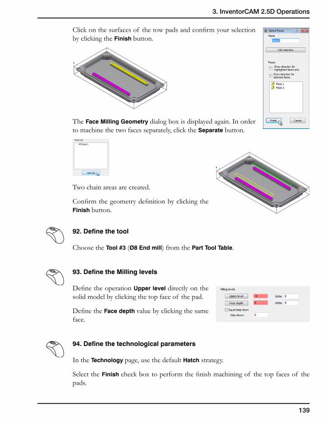
139
3. InventorCAM 2.5D Operations
Click on the surfaces of the tow pads and confirm your selection by clicking the Finish button.
The Face Milling Geometry dialog box is displayed again. In order to machine the two faces separately, click the Separate button.
Two chain areas are created.
Confirm the geometry definition by clicking the Finish button.
92. Define the tool
Choose the Tool #3 (Ø8 End mill) from the Part Tool Table.
93. Define the Milling levels
Define the operation Upper level directly on the solid model by clicking the top face of the pad.
Define the Face depth value by clicking the same face.
94. Define the technological parameters
In the Technology page, use the default Hatch strategy.
Select the Finish check box to perform the finish machining of the top faces of the pads.
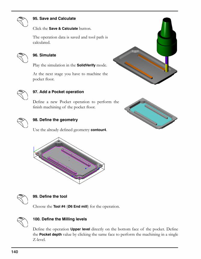
140
95. Save and Calculate
Click the Save & Calculate button.
The operation data is saved and tool path is calculated.
96. Simulate
Play the simulation in the SolidVerify mode.
At the next stage you have to machine the pocket floor.
97. Add a Pocket operation
Define a new Pocket operation to perform the finish machining of the pocket floor.
98. Define the geometry
Use the already defined geometry contour4.
99. Define the tool
Choose the Tool #4 (Ø6 End mill) for the operation.
100. Define the Milling levels
Define the operation Upper level directly on the bottom face of the pocket. Define the Pocket depth value by clicking the same face to perform the machining in a single Z-level.
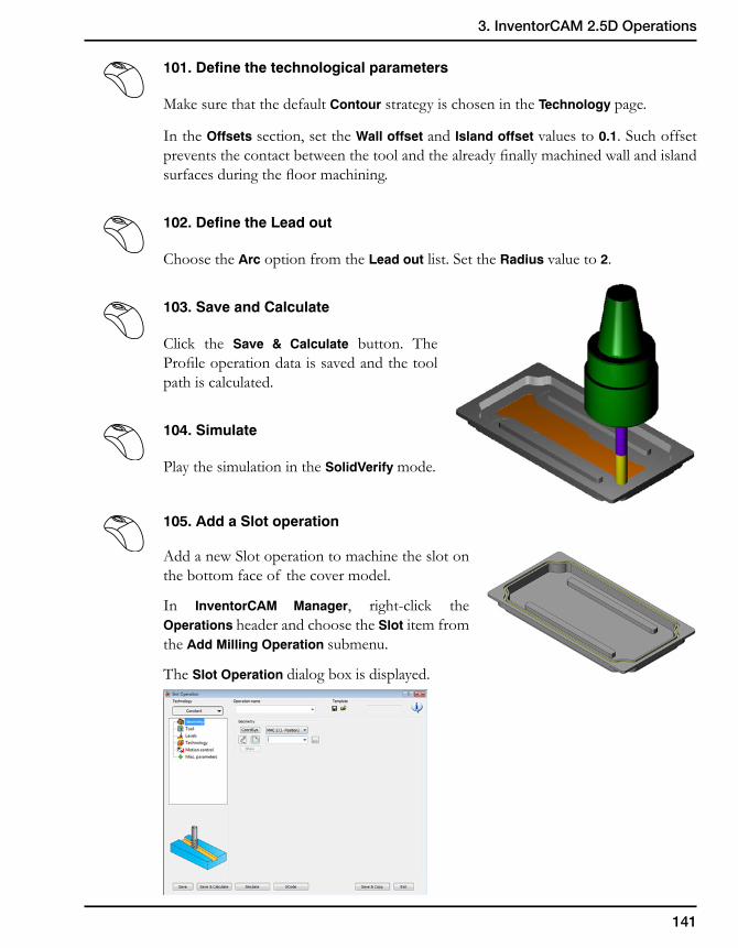
141
3. InventorCAM 2.5D Operations
101. Define the technological parameters
Make sure that the default Contour strategy is chosen in the Technology page.
In the Offsets section, set the Wall offset and Island offset values to 0.1. Such offset prevents the contact between the tool and the already finally machined wall and island surfaces during the floor machining.
102. Define the Lead out
Choose the Arc option from the Lead out list. Set the Radius value to 2.
103. Save and Calculate
Click the Save & Calculate button. The Profile operation data is saved and the tool path is calculated.
104. Simulate
Play the simulation in the SolidVerify mode.
105. Add a Slot operation
Add a new Slot operation to machine the slot on the bottom face of the cover model.
In InventorCAM Manager, right-click the Operations header and choose the Slot item from the Add Milling Operation submenu.
The Slot Operation dialog box is displayed.
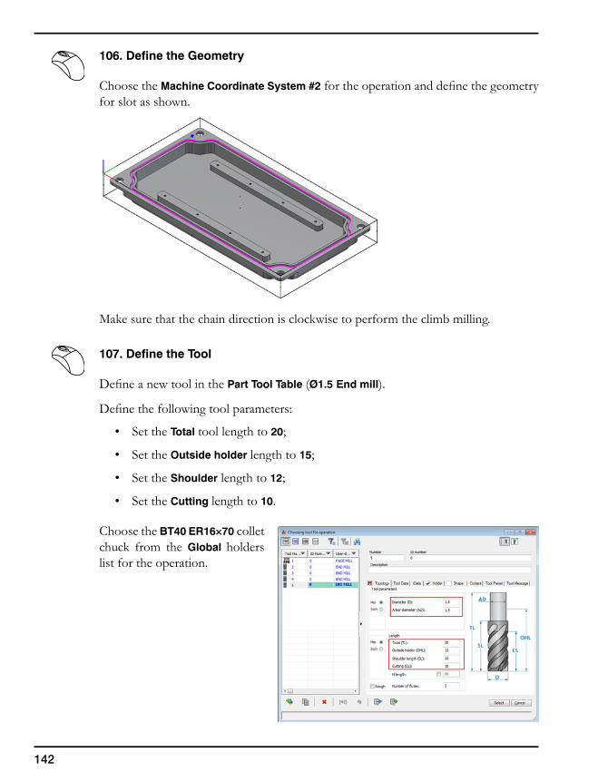
142
106. Define the Geometry
Choose the Machine Coordinate System #2 for the operation and define the geometry for slot as shown.
Make sure that the chain direction is clockwise to perform the climb milling.
107. Define the Tool
Define a new tool in the Part Tool Table (Ø1.5 End mill).
Define the following tool parameters:
• Set the Total tool length to 20;
• Set the Outside holder length to 15;
• Set the Shoulder length to 12;
• Set the Cutting length to 10.
Choose the BT40 ER16×70 collet chuck from the Global holders list for the operation.
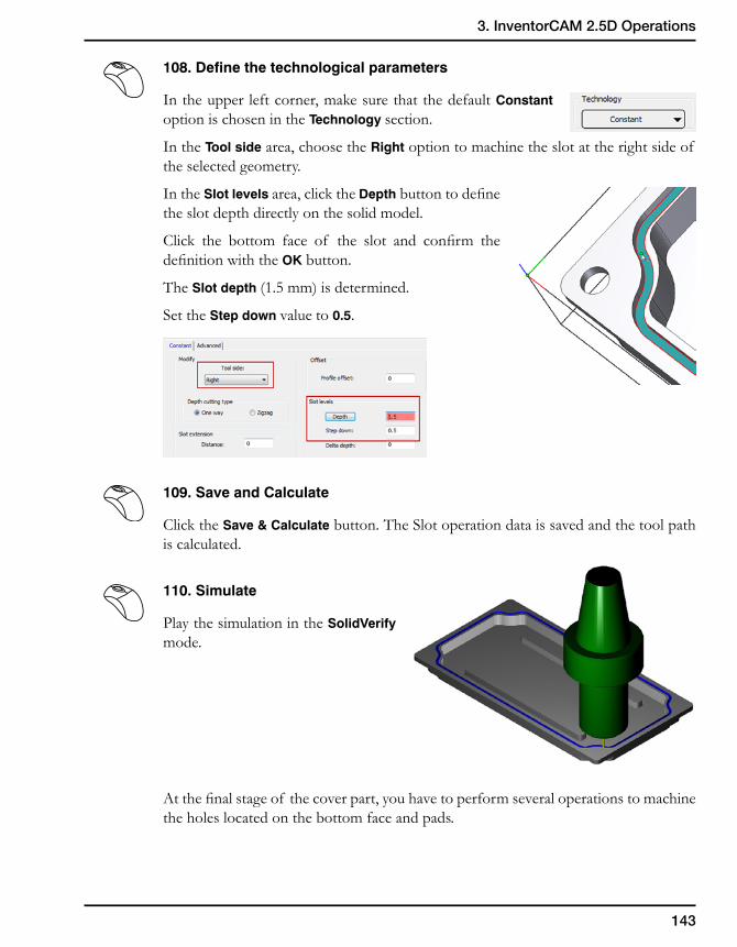
143
3. InventorCAM 2.5D Operations
108. Define the technological parameters
In the upper left corner, make sure that the default Constant option is chosen in the Technology section.
In the Tool side area, choose the Right option to machine the slot at the right side of the selected geometry.
In the Slot levels area, click the Depth button to define the slot depth directly on the solid model.
Click the bottom face of the slot and confirm the definition with the OK button.
The Slot depth (1.5 mm) is determined.
Set the Step down value to 0.5.
109. Save and Calculate
Click the Save & Calculate button. The Slot operation data is saved and the tool path is calculated.
110. Simulate
Play the simulation in the SolidVerify mode.
At the final stage of the cover part, you have to perform several operations to machine the holes located on the bottom face and pads.
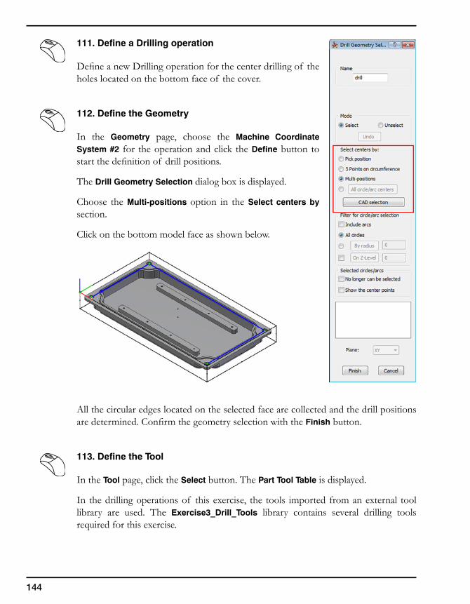
144
111. Define a Drilling operation
Define a new Drilling operation for the center drilling of the holes located on the bottom face of the cover.
112. Define the Geometry
In the Geometry page, choose the Machine Coordinate System #2 for the operation and click the Define button to start the definition of drill positions.
The Drill Geometry Selection dialog box is displayed.
Choose the Multi-positions option in the Select centers by section.
Click on the bottom model face as shown below.
All the circular edges located on the selected face are collected and the drill positions are determined. Confirm the geometry selection with the Finish button.
113. Define the Tool
In the Tool page, click the Select button. The Part Tool Table is displayed.
In the drilling operations of this exercise, the tools imported from an external tool library are used. The Exercise3_Drill_Tools library contains several drilling tools required for this exercise.
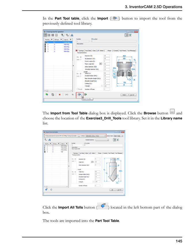
145
3. InventorCAM 2.5D Operations
In the Part Tool table, click the Import ( ) button to import the tool from the previously defined tool library.
The Import from Tool Table dialog box is displayed. Click the Browse button and choose the location of the Exercise3_Drill_Tools tool library. Set it in the Library name list.
Click the Import All Tolls button ( ) located in the left bottom part of the dialog box.
The tools are imported into the Part Tool Table.
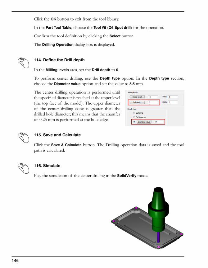
146
Click the OK button to exit from the tool library.
In the Part Tool Table, choose the Tool #6 (Ø6 Spot drill) for the operation.
Confirm the tool definition by clicking the Select button.
The Drilling Operation dialog box is displayed.
114. Define the Drill depth
In the Milling levels area, set the Drill depth to 0.
To perform center drilling, use the Depth type option. In the Depth type section, choose the Diameter value option and set the value to 5.5 mm.
The center drilling operation is performed until the specified diameter is reached at the upper level (the top face of the model). The upper diameter of the center drilling cone is greater than the drilled hole diameter; this means that the chamfer of 0.25 mm is performed at the hole edge.
115. Save and Calculate
Click the Save & Calculate button. The Drilling operation data is saved and the tool path is calculated.
116. Simulate
Play the simulation of the center drilling in the SolidVerify mode.
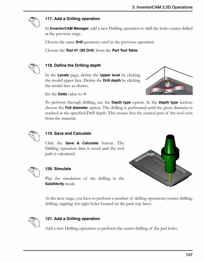
147
3. InventorCAM 2.5D Operations
117. Add a Drilling operation
In InventorCAM Manager, add a new Drilling operation to drill the holes center-drilled at the previous stage.
Choose the same Drill geometry used in the previous operation.
Choose the Tool #7 (Ø5 Drill) from the Part Tool Table.
118. Define the Drilling depth
In the Levels page, define the Upper level by clicking the model upper face. Define the Drill depth by clicking the model face as shown.
Set the Delta value to -1.
To perform through drilling, use the Depth type option. In the Depth type section, choose the Full diameter option. The drilling is performed until the given diameter is reached at the specified Drill depth. This means that the conical part of the tool exits from the material.
119. Save and Calculate
Click the Save & Calculate button. The Drilling operation data is saved and the tool path is calculated.
120. Simulate
Play the simulation of the drilling in the SolidVerify mode.
At the next stage, you have to perform a number of drilling operations (center drilling, drilling, tapping) for eight holes located on the pads top faces.
121. Add a Drilling operation
Add a new Drilling operation to perform the center drilling of the pad holes.
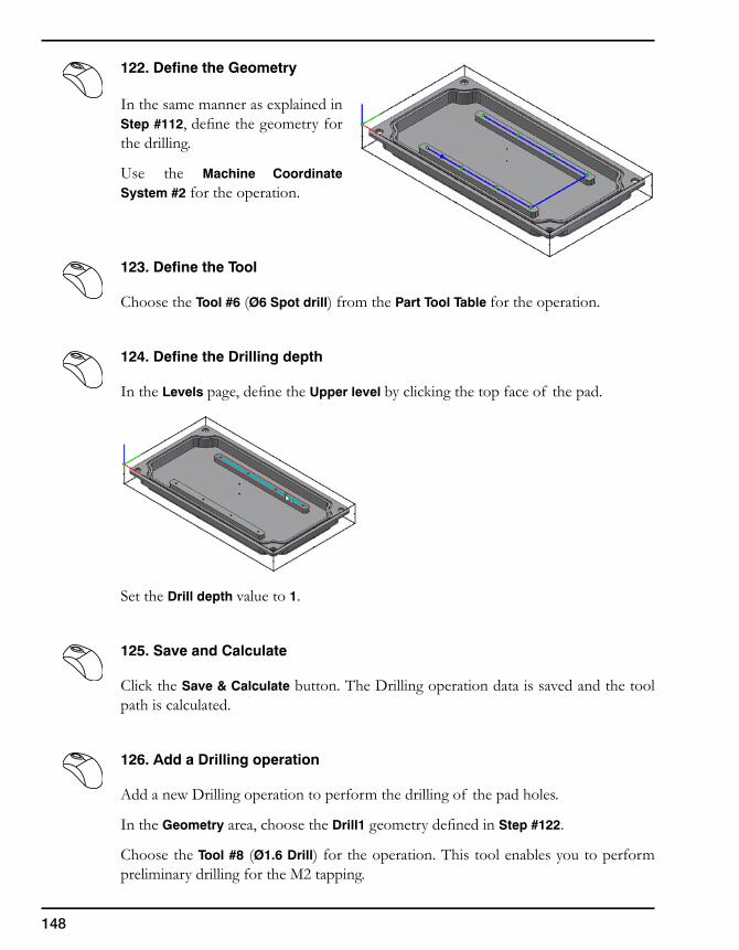
148
122. Define the Geometry
In the same manner as explained in Step #112, define the geometry for the drilling.
Use the Machine Coordinate System #2 for the operation.
123. Define the Tool
Choose the Tool #6 (Ø6 Spot drill) from the Part Tool Table for the operation.
124. Define the Drilling depth
In the Levels page, define the Upper level by clicking the top face of the pad.
Set the Drill depth value to 1.
125. Save and Calculate
Click the Save & Calculate button. The Drilling operation data is saved and the tool path is calculated.
126. Add a Drilling operation
Add a new Drilling operation to perform the drilling of the pad holes.
In the Geometry area, choose the Drill1 geometry defined in Step #122.
Choose the Tool #8 (Ø1.6 Drill) for the operation. This tool enables you to perform preliminary drilling for the M2 tapping.
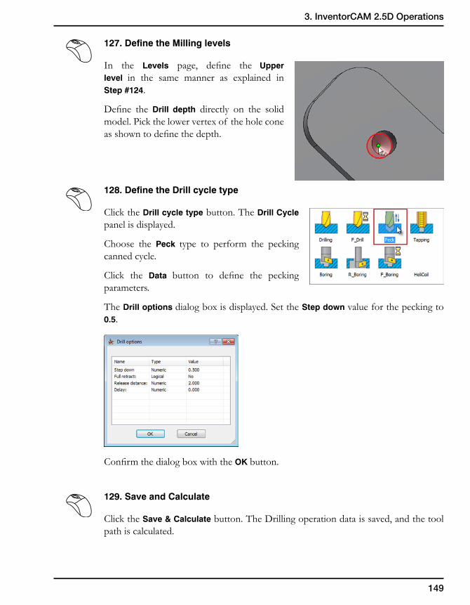
149
3. InventorCAM 2.5D Operations
127. Define the Milling levels
In the Levels page, define the Upper level in the same manner as explained in Step #124.
Define the Drill depth directly on the solid model. Pick the lower vertex of the hole cone as shown to define the depth.
128. Define the Drill cycle type
Click the Drill cycle type button. The Drill Cycle panel is displayed.
Choose the Peck type to perform the pecking canned cycle.
Click the Data button to define the pecking parameters.
The Drill options dialog box is displayed. Set the Step down value for the pecking to 0.5.
Confirm the dialog box with the OK button.
129. Save and Calculate
Click the Save & Calculate button. The Drilling operation data is saved, and the tool path is calculated.
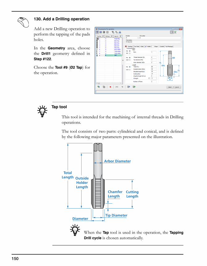
150
130. Add a Drilling operation
Add a new Drilling operation to perform the tapping of the pads holes.
In the Geometry area, choose the Drill1 geometry defined in Step #122.
Choose the Tool #9 (Ø2 Tap) for the operation.
Tap tool
This tool is intended for the machining of internal threads in Drilling operations.
The tool consists of two parts: cylindrical and conical, and is defined by the following major parameters presented on the illustration.
When the Tap tool is used in the operation, the Tapping Drill cycle is chosen automatically.
OutsideHolderLength
CuttingLength
Tip Diameter
ChamferLength
Diameter
TotalLength
Arbor Diameter
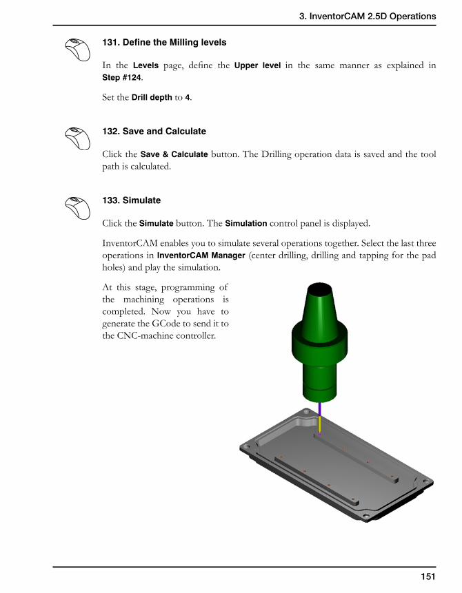
151
3. InventorCAM 2.5D Operations
131. Define the Milling levels
In the Levels page, define the Upper level in the same manner as explained in Step #124.
Set the Drill depth to 4.
132. Save and Calculate
Click the Save & Calculate button. The Drilling operation data is saved and the tool path is calculated.
133. Simulate
Click the Simulate button. The Simulation control panel is displayed.
InventorCAM enables you to simulate several operations together. Select the last three operations in InventorCAM Manager (center drilling, drilling and tapping for the pad holes) and play the simulation.
At this stage, programming of the machining operations is completed. Now you have to generate the GCode to send it to the CNC-machine controller.
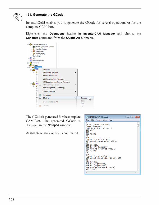
152
134. Generate the GCode
InventorCAM enables you to generate the GCode for several operations or for the complete CAM-Part.
Right-click the Operations header in InventorCAM Manager and choose the Generate command from the GCode All submenu.
The GCode is generated for the complete CAM-Part. The generated GCode is displayed in the Notepad window.
At this stage, the exercise is completed.
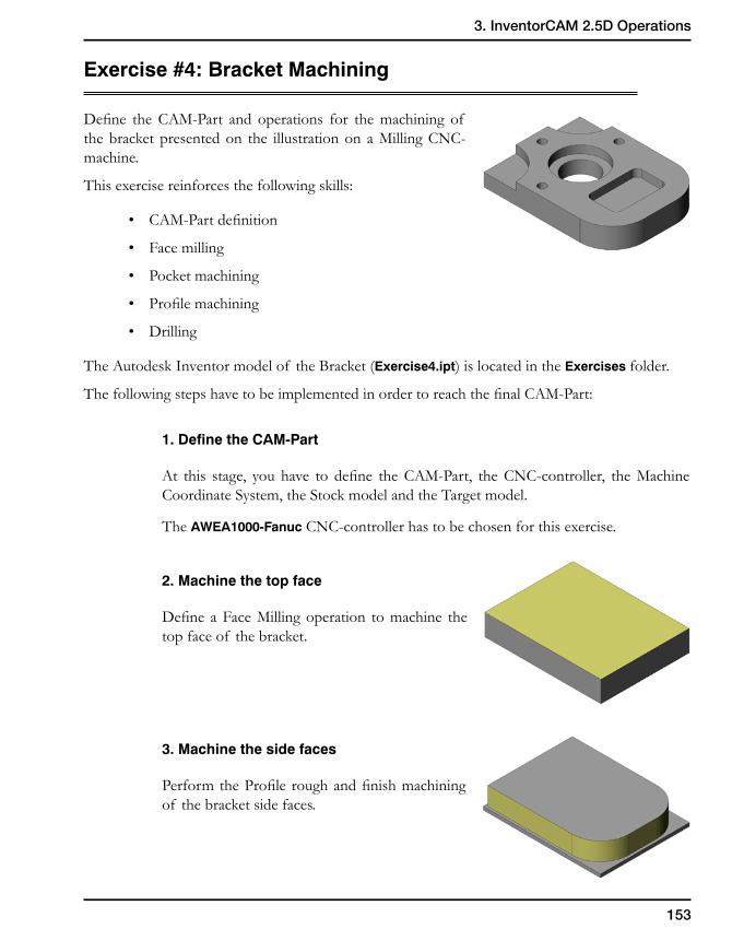
153
3. InventorCAM 2.5D Operations
Exercise #4: Bracket Machining
Define the CAM-Part and operations for the machining of the bracket presented on the illustration on a Milling CNC-machine.
This exercise reinforces the following skills:
• CAM-Part definition
• Face milling
• Pocket machining
• Profile machining
• Drilling
The Autodesk Inventor model of the Bracket (Exercise4.ipt) is located in the Exercises folder.
The following steps have to be implemented in order to reach the final CAM-Part:
1. Define the CAM-Part
At this stage, you have to define the CAM-Part, the CNC-controller, the Machine Coordinate System, the Stock model and the Target model.
The AWEA1000-Fanuc CNC-controller has to be chosen for this exercise.
2. Machine the top face
Define a Face Milling operation to machine the top face of the bracket.
3. Machine the side faces
Perform the Profile rough and finish machining of the bracket side faces.
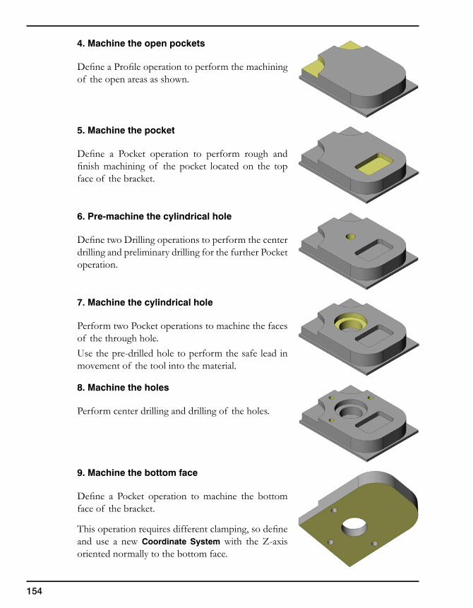
154
4. Machine the open pockets
Define a Profile operation to perform the machining of the open areas as shown.
5. Machine the pocket
Define a Pocket operation to perform rough and finish machining of the pocket located on the top face of the bracket.
6. Pre-machine the cylindrical hole
Define two Drilling operations to perform the center drilling and preliminary drilling for the further Pocket operation.
7. Machine the cylindrical hole
Perform two Pocket operations to machine the faces of the through hole.Use the pre-drilled hole to perform the safe lead in movement of the tool into the material.
8. Machine the holes
Perform center drilling and drilling of the holes.
9. Machine the bottom face
Define a Pocket operation to machine the bottom face of the bracket.
This operation requires different clamping, so define and use a new Coordinate System with the Z-axis oriented normally to the bottom face.
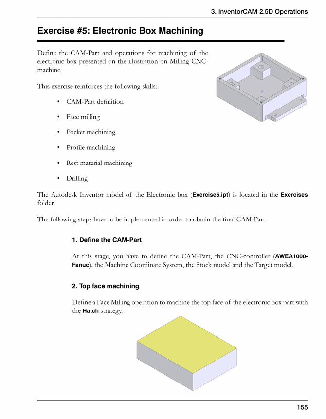
155
3. InventorCAM 2.5D Operations
Exercise #5: Electronic Box Machining
Define the CAM-Part and operations for machining of the electronic box presented on the illustration on Milling CNC-machine.
This exercise reinforces the following skills:
• CAM-Part definition
• Face milling
• Pocket machining
• Profile machining
• Rest material machining
• Drilling
The Autodesk Inventor model of the Electronic box (Exercise5.ipt) is located in the Exercises folder.
The following steps have to be implemented in order to obtain the final CAM-Part:
1. Define the CAM-Part
At this stage, you have to define the CAM-Part, the CNC-controller (AWEA1000-Fanuc), the Machine Coordinate System, the Stock model and the Target model.
2. Top face machining
Define a Face Milling operation to machine the top face of the electronic box part with the Hatch strategy.
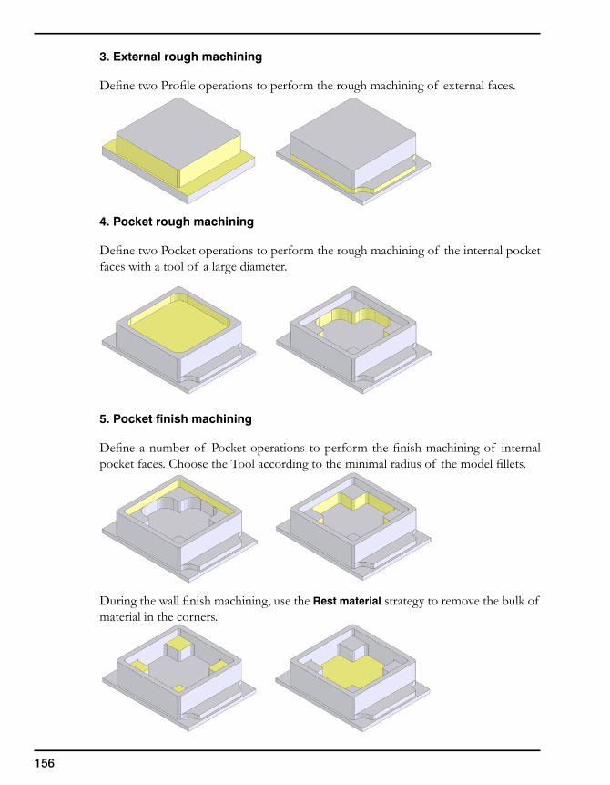
156
3. External rough machining
Define two Profile operations to perform the rough machining of external faces.
4. Pocket rough machining
Define two Pocket operations to perform the rough machining of the internal pocket faces with a tool of a large diameter.
5. Pocket finish machining
Define a number of Pocket operations to perform the finish machining of internal pocket faces. Choose the Tool according to the minimal radius of the model fillets.
During the wall finish machining, use the Rest material strategy to remove the bulk of material in the corners.
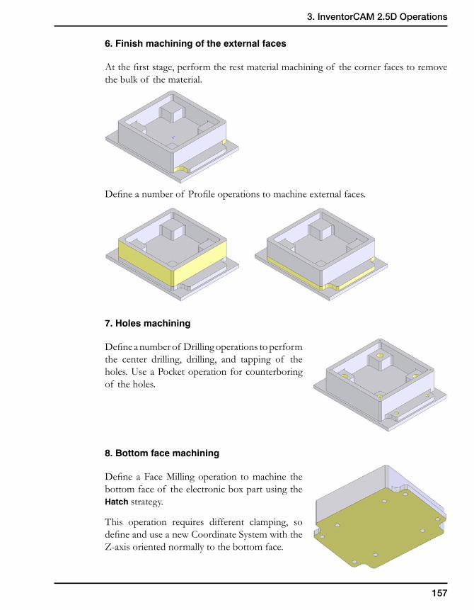
157
3. InventorCAM 2.5D Operations
6. Finish machining of the external faces
At the first stage, perform the rest material machining of the corner faces to remove the bulk of the material.
Define a number of Profile operations to machine external faces.
7. Holes machining
Define a number of Drilling operations to perform the center drilling, drilling, and tapping of the holes. Use a Pocket operation for counterboring of the holes.
8. Bottom face machining
Define a Face Milling operation to machine the bottom face of the electronic box part using the Hatch strategy.
This operation requires different clamping, so define and use a new Coordinate System with the Z-axis oriented normally to the bottom face.
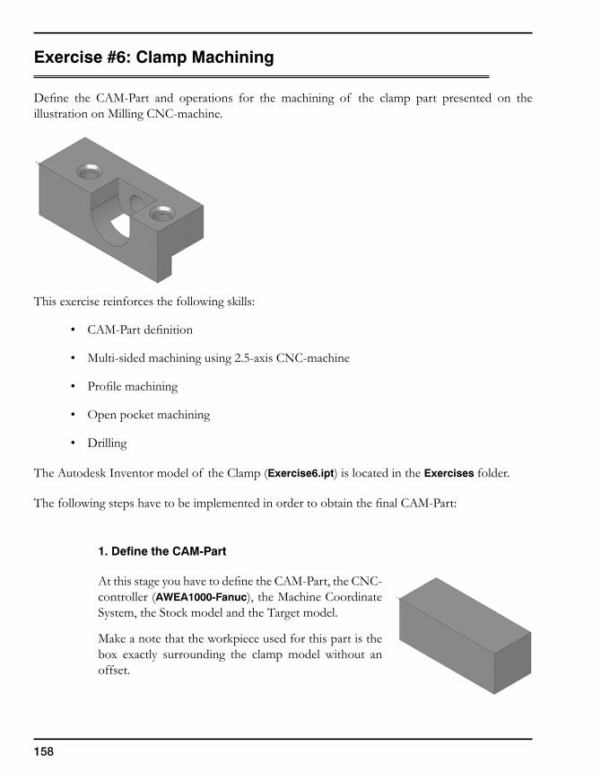
158
Exercise #6: Clamp Machining
Define the CAM-Part and operations for the machining of the clamp part presented on the illustration on Milling CNC-machine.
This exercise reinforces the following skills:
• CAM-Part definition
• Multi-sided machining using 2.5-axis CNC-machine
• Profile machining
• Open pocket machining
• Drilling
The Autodesk Inventor model of the Clamp (Exercise6.ipt) is located in the Exercises folder.
The following steps have to be implemented in order to obtain the final CAM-Part:
1. Define the CAM-Part
At this stage you have to define the CAM-Part, the CNC-controller (AWEA1000-Fanuc), the Machine Coordinate System, the Stock model and the Target model.
Make a note that the workpiece used for this part is the box exactly surrounding the clamp model without an offset.

159
3. InventorCAM 2.5D Operations
2. Holes machining
Perform several Drilling operations to machine the holes.
Use the appropriate Machine Coordinate System defined for the positioning shown below.
3. Open pocket machining
Define the Machine Coordinate System for the positioning shown below to machine the open pocket.
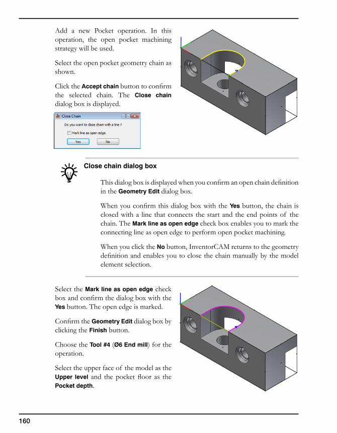
160
Add a new Pocket operation. In this operation, the open pocket machining strategy will be used.
Select the open pocket geometry chain as shown.
Click the Accept chain button to confirm the selected chain. The Close chain dialog box is displayed.
Close chain dialog box
This dialog box is displayed when you confirm an open chain definition in the Geometry Edit dialog box.
When you confirm this dialog box with the Yes button, the chain is closed with a line that connects the start and the end points of the chain. The Mark line as open edge check box enables you to mark the connecting line as open edge to perform open pocket machining.
When you click the No button, InventorCAM returns to the geometry definition and enables you to close the chain manually by the model element selection.
Select the Mark line as open edge check box and confirm the dialog box with the Yes button. The open edge is marked.
Confirm the Geometry Edit dialog box by clicking the Finish button.
Choose the Tool #4 (Ø6 End mill) for the operation.
Select the upper face of the model as the Upper level and the pocket floor as the Pocket depth.
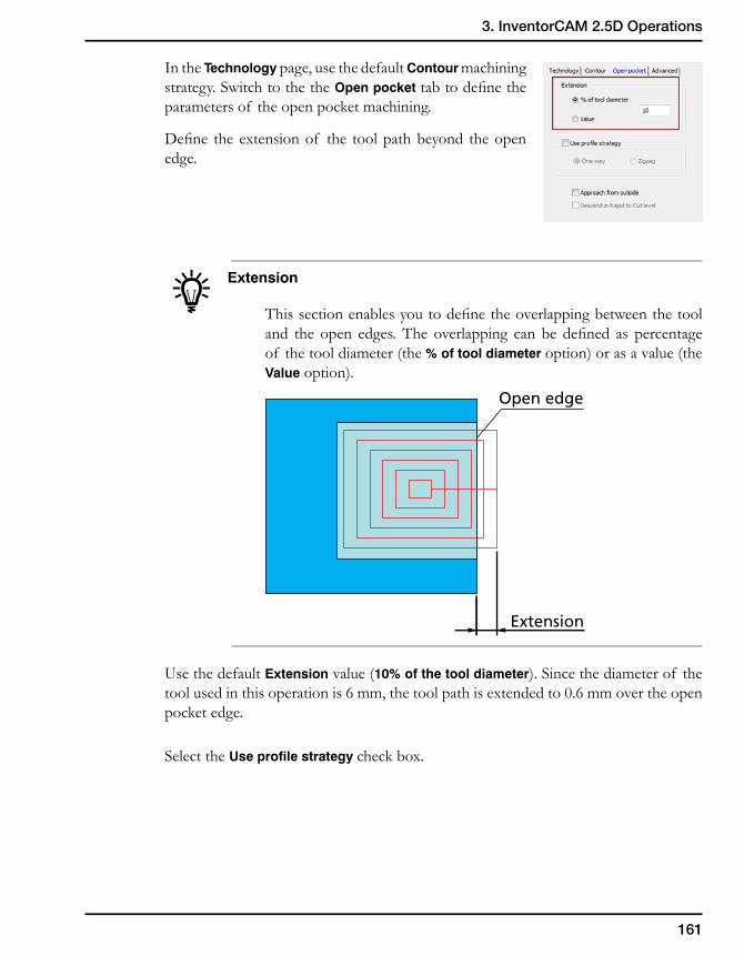
161
3. InventorCAM 2.5D Operations
In the Technology page, use the default Contour machining strategy. Switch to the the Open pocket tab to define the parameters of the open pocket machining.
Define the extension of the tool path beyond the open edge.
Extension
This section enables you to define the overlapping between the tool and the open edges. The overlapping can be defined as percentage of the tool diameter (the % of tool diameter option) or as a value (the Value option).
Use the default Extension value (10% of the tool diameter). Since the diameter of the tool used in this operation is 6 mm, the tool path is extended to 0.6 mm over the open pocket edge.
Select the Use profile strategy check box.
Extension
Open edge
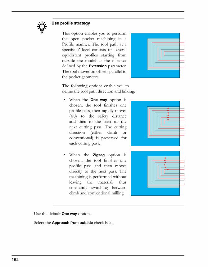
162
Use profile strategy
This option enables you to perform the open pocket machining in a Profile manner. The tool path at a specific Z-level consists of several equidistant profiles starting from outside the model at the distance defined by the Extension parameter. The tool moves on offsets parallel to the pocket geometry.
The following options enable you to define the tool path direction and linking:
• When the One way option is chosen, the tool finishes one profile pass, then rapidly moves (G0) to the safety distance and then to the start of the next cutting pass. The cutting direction (either climb or conventional) is preserved for each cutting pass.
• When the Zigzag option is chosen, the tool finishes one profile pass and then moves directly to the next pass. The machining is performed without leaving the material, thus constantly switching between climb and conventional milling.
Use the default One way option.
Select the Approach from outside check box.
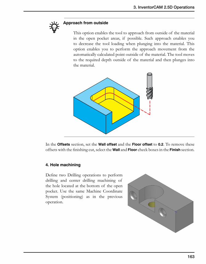
163
3. InventorCAM 2.5D Operations
Approach from outside
This option enables the tool to approach from outside of the material in the open pocket areas, if possible. Such approach enables you to decrease the tool loading when plunging into the material. This option enables you to perform the approach movement from the automatically calculated point outside of the material. The tool moves to the required depth outside of the material and then plunges into the material.
In the Offsets section, set the Wall offset and the Floor offset to 0.2. To remove these offsets with the finishing cut, select the Wall and Floor check boxes in the Finish section.
4. Hole machining
Define two Drilling operations to perform drilling and center drilling machining of the hole located at the bottom of the open pocket. Use the same Machine Coordinate System (positioning) as in the previous operation.
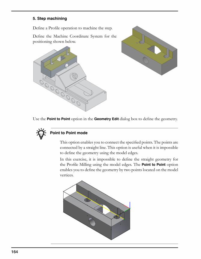
164
5. Step machining
Define a Profile operation to machine the step.
Define the Machine Coordinate System for the positioning shown below.
Use the Point to Point option in the Geometry Edit dialog box to define the geometry.
Point to Point mode
This option enables you to connect the specified points. The points are connected by a straight line. This option is useful when it is impossible to define the geometry using the model edges.In this exercise, it is impossible to define the straight geometry for the Profile Milling using the model edges. The Point to Point option enables you to define the geometry by two points located on the model vertices.
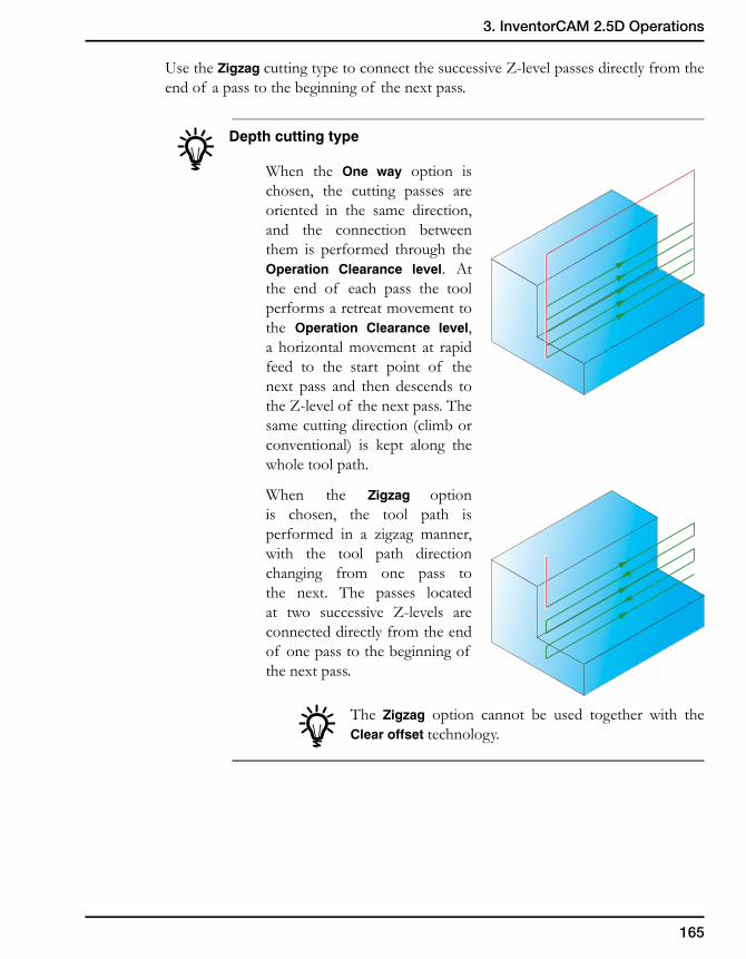
165
3. InventorCAM 2.5D Operations
Use the Zigzag cutting type to connect the successive Z-level passes directly from the end of a pass to the beginning of the next pass.
Depth cutting type
When the One way option is chosen, the cutting passes are oriented in the same direction, and the connection between them is performed through the Operation Clearance level. At the end of each pass the tool performs a retreat movement to the Operation Clearance level, a horizontal movement at rapid feed to the start point of the next pass and then descends to the Z-level of the next pass. The same cutting direction (climb or conventional) is kept along the whole tool path.
When the Zigzag option is chosen, the tool path is performed in a zigzag manner, with the tool path direction changing from one pass to the next. The passes located at two successive Z-levels are connected directly from the end of one pass to the beginning of the next pass.
The Zigzag option cannot be used together with the Clear offset technology.
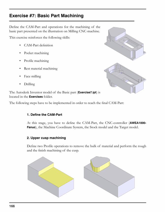
166
Exercise #7: Basic Part Machining
Define the CAM-Part and operations for the machining of the basic part presented on the illustration on Milling CNC-machine.
This exercise reinforces the following skills:
• CAM-Part definition
• Pocket machining
• Profile machining
• Rest material machining
• Face milling
• Drilling
The Autodesk Inventor model of the Basic part (Exercise7.ipt) is located in the Exercises folder.
The following steps have to be implemented in order to reach the final CAM-Part:
1. Define the CAM-Part
At this stage, you have to define the CAM-Part, the CNC-controller (AWEA1000-Fanuc), the Machine Coordinate System, the Stock model and the Target model.
2. Upper cusp machining
Define two Profile operations to remove the bulk of material and perform the rough and the finish machining of the cusp.
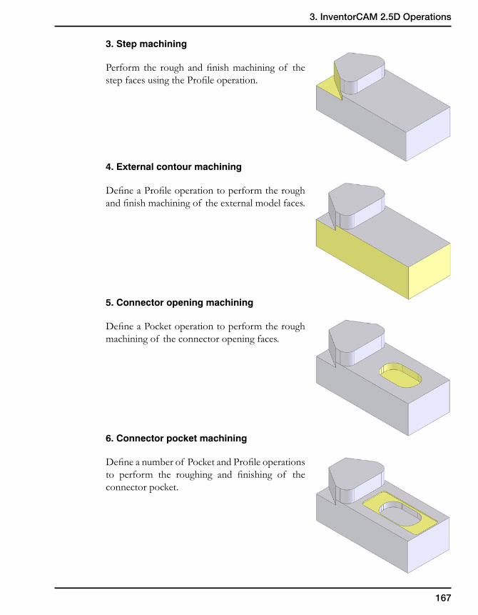
167
3. InventorCAM 2.5D Operations
3. Step machining
Perform the rough and finish machining of the step faces using the Profile operation.
4. External contour machining
Define a Profile operation to perform the rough and finish machining of the external model faces.
5. Connector opening machining
Define a Pocket operation to perform the rough machining of the connector opening faces.
6. Connector pocket machining
Define a number of Pocket and Profile operations to perform the roughing and finishing of the connector pocket.
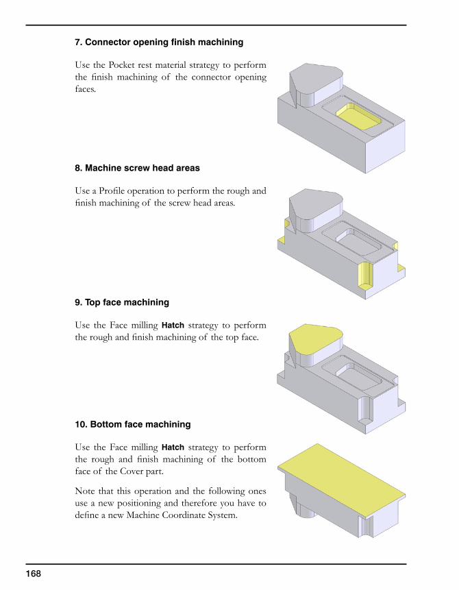
168
7. Connector opening finish machining
Use the Pocket rest material strategy to perform the finish machining of the connector opening faces.
8. Machine screw head areas
Use a Profile operation to perform the rough and finish machining of the screw head areas.
9. Top face machining
Use the Face milling Hatch strategy to perform the rough and finish machining of the top face.
10. Bottom face machining
Use the Face milling Hatch strategy to perform the rough and finish machining of the bottom face of the Cover part.
Note that this operation and the following ones use a new positioning and therefore you have to define a new Machine Coordinate System.
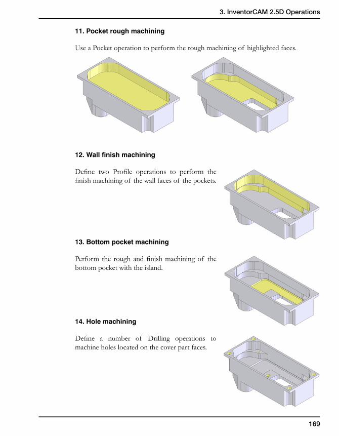
169
3. InventorCAM 2.5D Operations
11. Pocket rough machining
Use a Pocket operation to perform the rough machining of highlighted faces.
12. Wall finish machining
Define two Profile operations to perform the finish machining of the wall faces of the pockets.
13. Bottom pocket machining
Perform the rough and finish machining of the bottom pocket with the island.
14. Hole machining
Define a number of Drilling operations to machine holes located on the cover part faces.
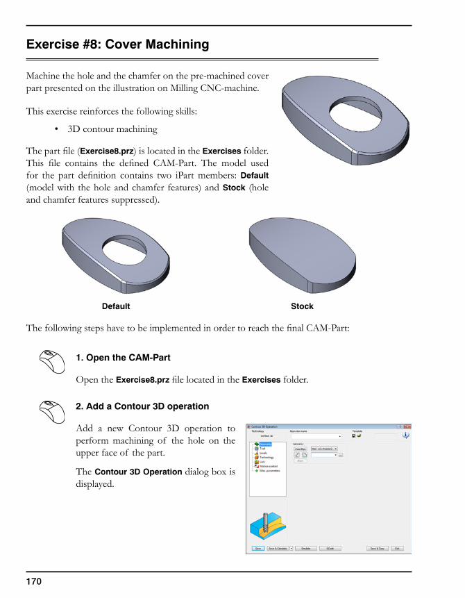
170
Exercise #8: Cover Machining
Machine the hole and the chamfer on the pre-machined cover part presented on the illustration on Milling CNC-machine.
This exercise reinforces the following skills:
• 3D contour machining
The part file (Exercise8.prz) is located in the Exercises folder. This file contains the defined CAM-Part. The model used for the part definition contains two iPart members: Default (model with the hole and chamfer features) and Stock (hole and chamfer features suppressed).
Default Stock
The following steps have to be implemented in order to reach the final CAM-Part:
1. Open the CAM-Part
Open the Exercise8.prz file located in the Exercises folder.
2. Add a Contour 3D operation
Add a new Contour 3D operation to perform machining of the hole on the upper face of the part.
The Contour 3D Operation dialog box is displayed.
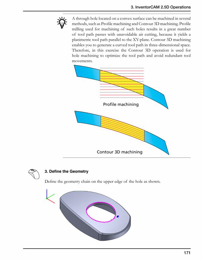
171
3. InventorCAM 2.5D Operations
A through hole located on a convex surface can be machined in several methods, such as Profile machining and Contour 3D machining. Profile milling used for machining of such holes results in a great number of tool path passes with unavoidable air cutting, because it yields a planimetric tool path parallel to the XY-plane. Contour 3D machining enables you to generate a curved tool path in three-dimensional space. Therefore, in this exercise the Contour 3D operation is used for hole machining to optimize the tool path and avoid redundant tool movements.
3. Define the Geometry
Define the geometry chain on the upper edge of the hole as shown.
Profile machining
Contour 3D machining
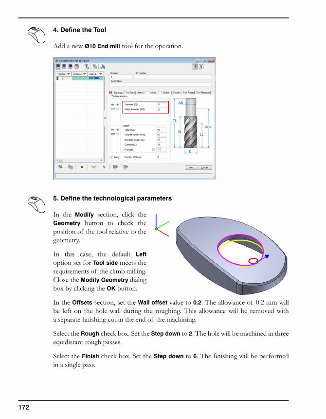
172
4. Define the Tool
Add a new Ø10 End mill tool for the operation.
5. Define the technological parameters
In the Modify section, click the Geometry button to check the position of the tool relative to the geometry.
In this case, the default Left option set for Tool side meets the requirements of the climb milling. Close the Modify Geometry dialog box by clicking the OK button.
In the Offsets section, set the Wall offset value to 0.2. The allowance of 0.2 mm will be left on the hole wall during the roughing. This allowance will be removed with a separate finishing cut in the end of the machining.
Select the Rough check box. Set the Step down to 2. The hole will be machined in three equidistant rough passes.
Select the Finish check box. Set the Step down to 6. The finishing will be performed in a single pass.
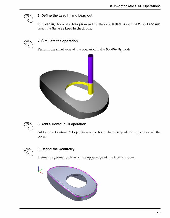
173
3. InventorCAM 2.5D Operations
6. Define the Lead in and Lead out
For Lead in, choose the Arc option and use the default Radius value of 2. For Lead out, select the Same as Lead in check box.
7. Simulate the operation
Perform the simulation of the operation in the SolidVerify mode.
8. Add a Contour 3D operation
Add a new Contour 3D operation to perform chamfering of the upper face of the cover.
9. Define the Geometry
Define the geometry chain on the upper edge of the face as shown.
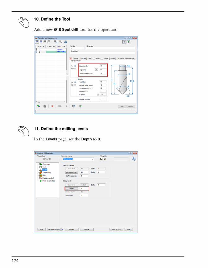
174
10. Define the Tool
Add a new Ø10 Spot drill tool for the operation.
11. Define the milling levels
In the Levels page, set the Depth to 0.
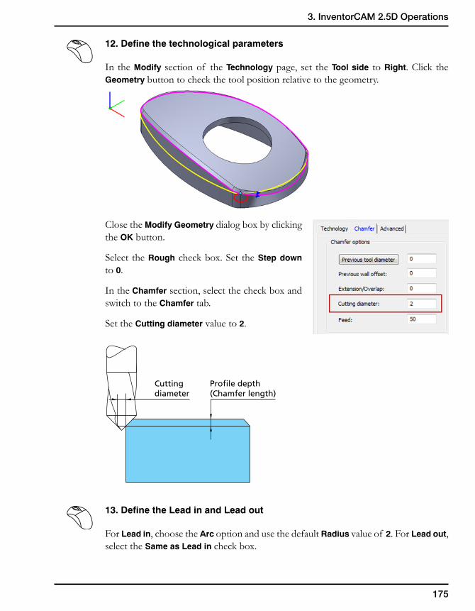
175
3. InventorCAM 2.5D Operations
12. Define the technological parameters
In the Modify section of the Technology page, set the Tool side to Right. Click the Geometry button to check the tool position relative to the geometry.
Close the Modify Geometry dialog box by clicking the OK button.
Select the Rough check box. Set the Step down to 0.
In the Chamfer section, select the check box and switch to the Chamfer tab.
Set the Cutting diameter value to 2.
13. Define the Lead in and Lead out
For Lead in, choose the Arc option and use the default Radius value of 2. For Lead out, select the Same as Lead in check box.
Cuttingdiameter
Profile depth(Chamfer length)

176
14. Simulate the operation
Perform the simulation of the operation in the SolidVerify mode.
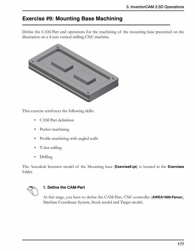
177
3. InventorCAM 2.5D Operations
Exercise #9: Mounting Base Machining
Define the CAM-Part and operations for the machining of the mounting base presented on the illustration on a 4-axis vertical milling CNC-machine.
This exercise reinforces the following skills:
• CAM-Part definition
• Pocket machining
• Profile machining with angled walls
• T-slot milling
• Drilling
The Autodesk Inventor model of the Mounting base (Exercise9.ipt) is located in the Exercises folder.
1. Define the CAM-Part
At this stage, you have to define the CAM-Part, CNC-controller (AWEA1000-Fanuc), Machine Coordinate System, Stock model and Target model.
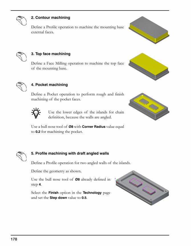
178
2. Contour machining
Define a Profile operation to machine the mounting base external faces.
3. Top face machining
Define a Face Milling operation to machine the top face of the mounting base.
4. Pocket machining
Define a Pocket operation to perform rough and finish machining of the pocket faces.
Use the lower edges of the islands for chain definition, because the walls are angled.
Use a bull nose tool of Ø8 with Corner Radius value equal to 0.2 for machining the pocket.
5. Profile machining with draft angled walls
Define a Profile operation for two angled walls of the islands.
Define the geometry as shown.
Use the bull nose tool of Ø8 already defined in step 4.
Select the Finish option in the Technology page and set the Step down value to 0.5.
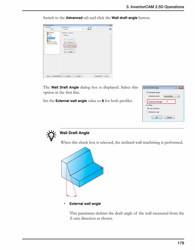
179
3. InventorCAM 2.5D Operations
Switch to the Advanced tab and click the Wall draft angle button.
The Wall Draft Angle dialog box is displayed. Select this option in the first line.
Set the External wall angle value to 8 for both profiles.
Wall Draft Angle
When this check box is selected, the inclined wall machining is performed.
• Externalwallangle
This parameter defines the draft angle of the wall measured from the Z-axis direction as shown.
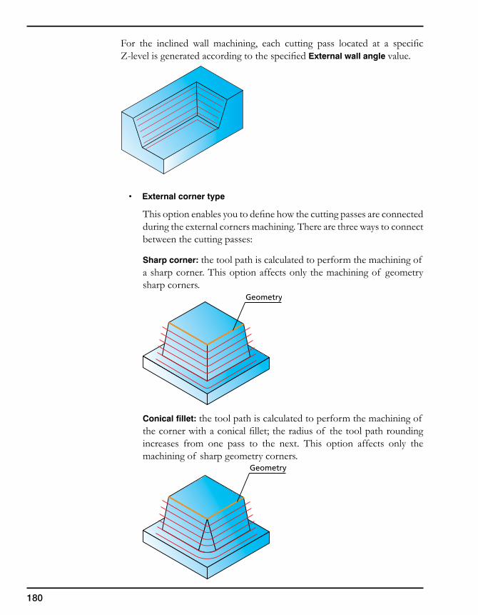
180
For the inclined wall machining, each cutting pass located at a specific Z-level is generated according to the specified External wall angle value.
• Externalcornertype
This option enables you to define how the cutting passes are connected during the external corners machining. There are three ways to connect between the cutting passes:
Sharp corner: the tool path is calculated to perform the machining of a sharp corner. This option affects only the machining of geometry sharp corners.
Conical fillet: the tool path is calculated to perform the machining of the corner with a conical fillet; the radius of the tool path rounding increases from one pass to the next. This option affects only the machining of sharp geometry corners.
Geometry
Geometry
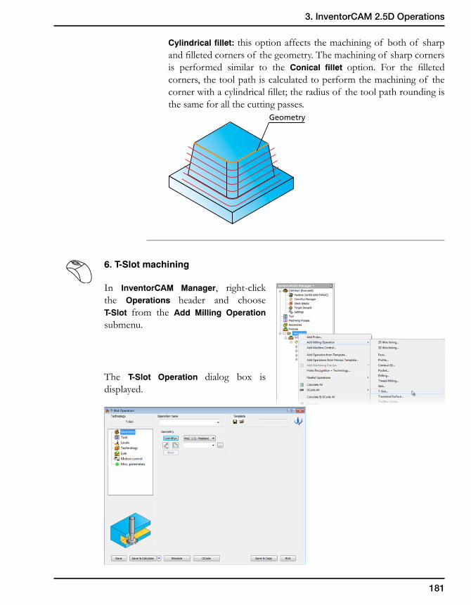
181
3. InventorCAM 2.5D Operations
Cylindrical fillet: this option affects the machining of both of sharp and filleted corners of the geometry. The machining of sharp corners is performed similar to the Conical fillet option. For the filleted corners, the tool path is calculated to perform the machining of the corner with a cylindrical fillet; the radius of the tool path rounding is the same for all the cutting passes.
6. T-Slot machining
In InventorCAM Manager, right-click the Operations header and choose T-Slot from the Add Milling Operation submenu.
The T-Slot Operation dialog box is displayed.
Geometry
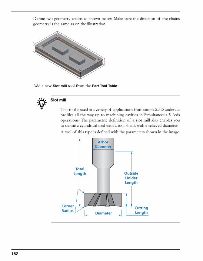
182
Define two geometry chains as shown below. Make sure the direction of the chains geometry is the same as on the illustration.
Add a new Slot mill tool from the Part Tool Table.
Slot mill
This tool is used in a variety of applications from simple 2.5D undercut profiles all the way up to machining cavities in Simultaneous 5 Axis operations. The parametric definition of a slot mill also enables you to define a cylindrical tool with a tool shank with a relieved diameter. A tool of this type is defined with the parameters shown in the image.
OutsideHolderLength
CuttingLengthDiameter
CornerRadius
TotalLength
ArborDiameter
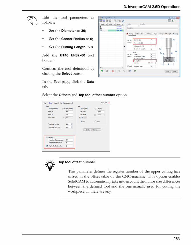
183
3. InventorCAM 2.5D Operations
Edit the tool parameters as follows:
• SettheDiameter to 36;
• SettheCorner Radius to 0;
• SettheCutting Length to 3.
Add the BT40 ER32x60 tool holder.
Confirm the tool definition byclicking the Select button.
In the Tool page, click the Data tab.
SelecttheOffsets and Top tool offset number option.
Top tool offset number
Thisparameterdefinestheregisternumberof theuppercuttingfaceoffset, intheoffsettableof theCNC-machine.ThisoptionenablesSolidCAMtoautomaticallytakeintoaccounttheminorsizedifferencesbetween the defined tool and the one actually used for cutting theworkpiece,if thereareany.
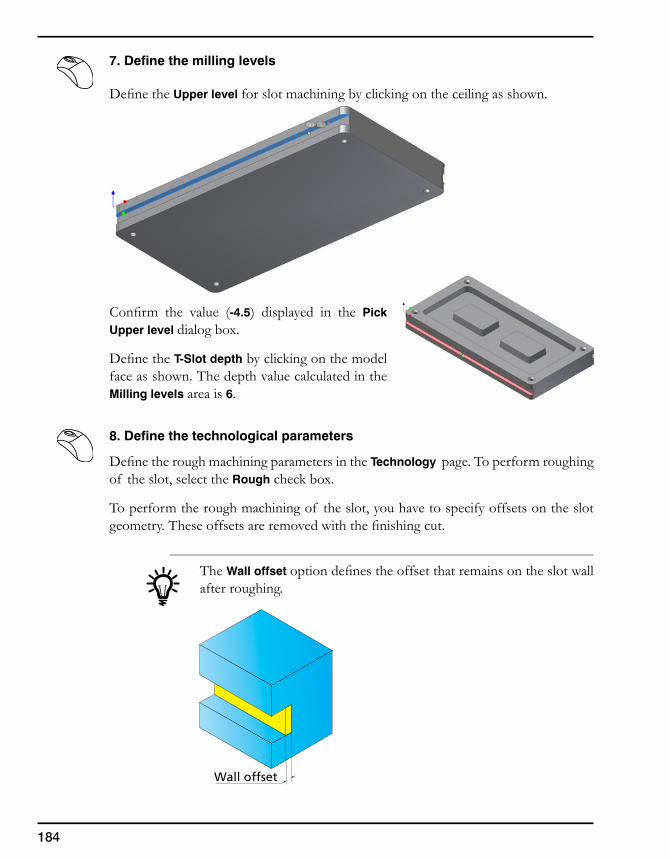
184
7. Define the milling levels
DefinetheUpper level forslotmachiningbyclickingontheceilingasshown.
Confirm the value (-4.5) displayed in the Pick Upper level dialogbox.
DefinetheT-Slot depthbyclickingonthemodelfaceasshown.ThedepthvaluecalculatedintheMilling levels area is 6.
8. Define the technological parameters
DefinetheroughmachiningparametersintheTechnology page.Toperformroughingof the slot, select the Roughcheckbox.
Toperformtheroughmachiningof theslot,youhavetospecifyoffsetsontheslotgeometry.Theseoffsetsareremovedwiththefinishingcut.
The Wall offset optiondefinestheoffsetthatremainsontheslotwallafterroughing.
Wall offset
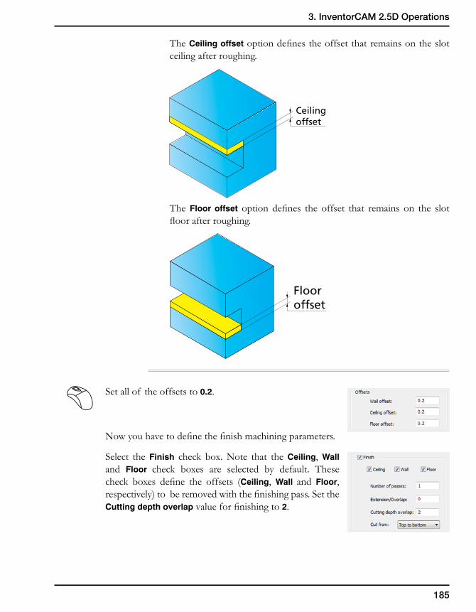
185
3. InventorCAM 2.5D Operations
The Ceiling offset option defines the offset that remains on the slot ceiling after roughing.
The Floor offset option defines the offset that remains on the slot floor after roughing.
Set all of the offsets to 0.2.
Now you have to define the finish machining parameters.
Select the Finish check box. Note that the Ceiling, Wall and Floor check boxes are selected by default. These check boxes define the offsets (Ceiling, Wall and Floor, respectively) to be removed with the finishing pass. Set the Cutting depth overlap value for finishing to 2.
Ceilingoffset
Flooroffset
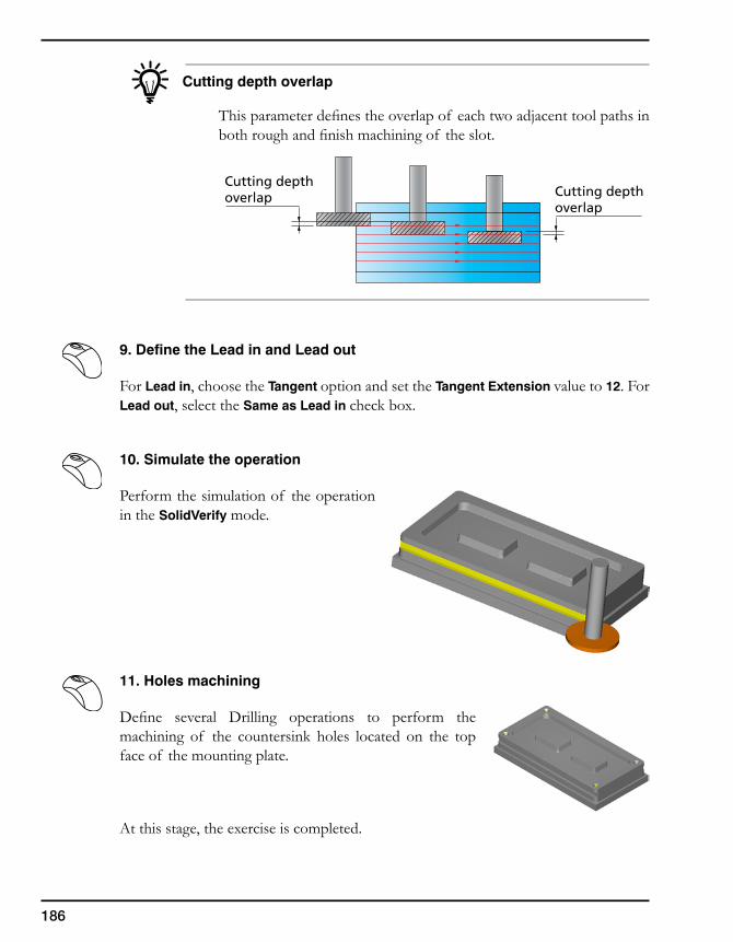
186
Cutting depthoverlap
Cutting depthoverlap
Cutting depth overlap
This parameter defines the overlap of each two adjacent tool paths in both rough and finish machining of the slot.
9. Define the Lead in and Lead out
For Lead in, choose the Tangent option and set the Tangent Extension value to 12. For Lead out, select the Same as Lead in check box.
10. Simulate the operation
Perform the simulation of the operation in the SolidVerify mode.
11. Holes machining
Define several Drilling operations to perform the machining of the countersink holes located on the top face of the mounting plate.
At this stage, the exercise is completed.
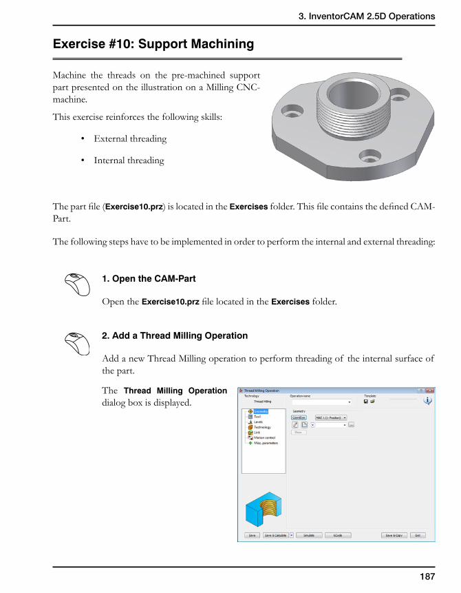
187
3. InventorCAM 2.5D Operations
Exercise #10: Support Machining
Machine the threads on the pre-machined support part presented on the illustration on a Milling CNC-machine.
This exercise reinforces the following skills:
• External threading
• Internal threading
The part file (Exercise10.prz) is located in the Exercises folder. This file contains the defined CAM-Part.
The following steps have to be implemented in order to perform the internal and external threading:
1. Open the CAM-Part
Open the Exercise10.prz file located in the Exercises folder.
2. Add a Thread Milling Operation
Add a new Thread Milling operation to perform threading of the internal surface of the part.
The Thread Milling Operation dialog box is displayed.
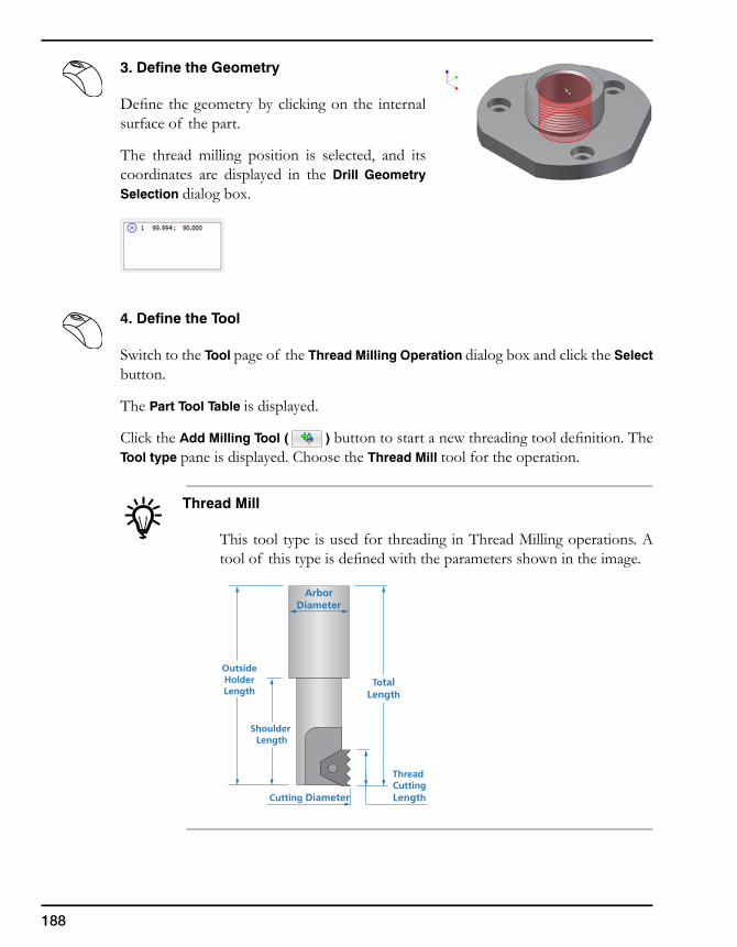
188
3. Define the Geometry
Define the geometry by clicking on the internal surface of the part.
The thread milling position is selected, and its coordinates are displayed in the Drill Geometry Selection dialog box.
4. Define the Tool
Switch to the Tool page of the Thread Milling Operation dialog box and click the Select button.
The Part Tool Table is displayed.
Click the Add Milling Tool ( ) button to start a new threading tool definition. The Tool type pane is displayed. Choose the Thread Mill tool for the operation.
Thread Mill
This tool type is used for threading in Thread Milling operations. A tool of this type is defined with the parameters shown in the image.
ArborDiameter
TotalLength
Thread CuttingLengthCutting Diameter
Shoulder Length
OutsideHolderLength
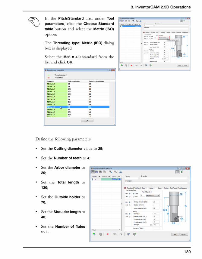
189
3. InventorCAM 2.5D Operations
In the Pitch/Standard area under Tool parameters, click the Choose Standard table button and select the Metric (ISO) option.
The Threading type: Metric (ISO) dialog box is displayed.
Select the M36 x 4.0 standard from the list and click OK.
Define the following parameters:
• Set the Cutting diameter value to 25;
• Set the Number of teeth to 4;
• Set the Arbor diameter to 20;
• Set the Total length to 120;
• Set the Outside holder to 70;
• Set the Shoulder length to 40;
• Set the Number of flutes to 1.
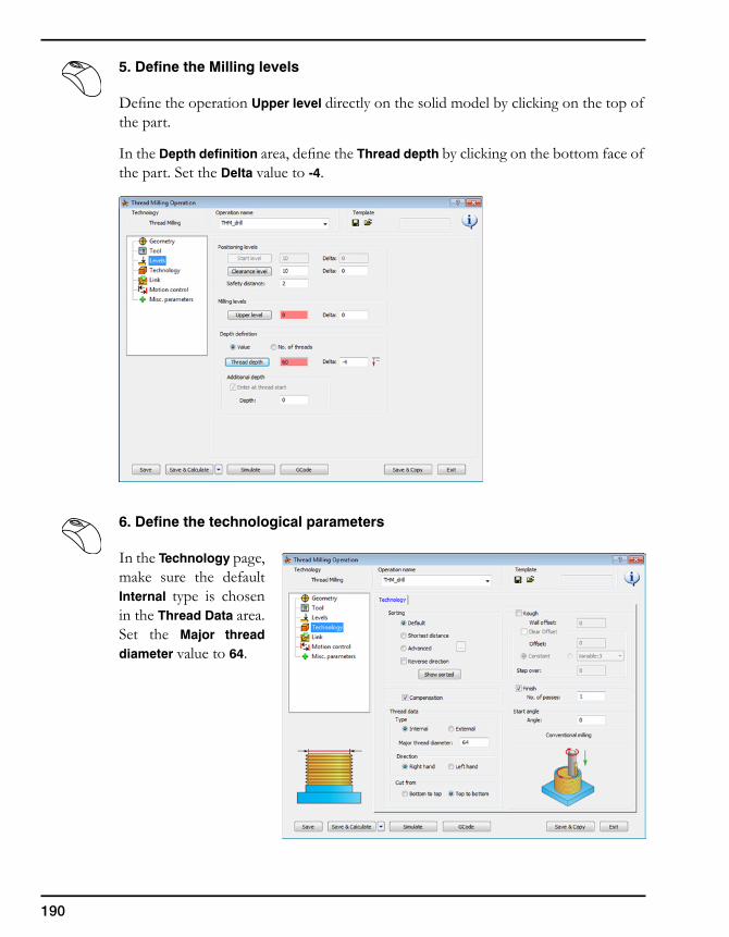
190
5. Define the Milling levels
Define the operation Upper level directly on the solid model by clicking on the top of the part.
In the Depth definition area, define the Thread depth by clicking on the bottom face of the part. Set the Delta value to -4.
6. Define the technological parameters
In the Technology page, make sure the default Internal type is chosen in the Thread Data area. Set the Major thread diameter value to 64.
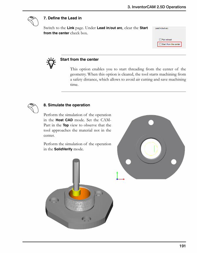
191
3. InventorCAM 2.5D Operations
7. Define the Lead in
Switch to the Link page. Under Lead in/out arc, clear the Start from the center check box.
Start from the center
This option enables you to start threading from the center of the geometry. When this option is cleared, the tool starts machining from a safety distance, which allows to avoid air cutting and save machining time.
8. Simulate the operation
Perform the simulation of the operation in the Host CAD mode. Set the CAM-Part in the Top view to observe that the tool approaches the material not in the center.
Perform the simulation of the operation in the SolidVerify mode.
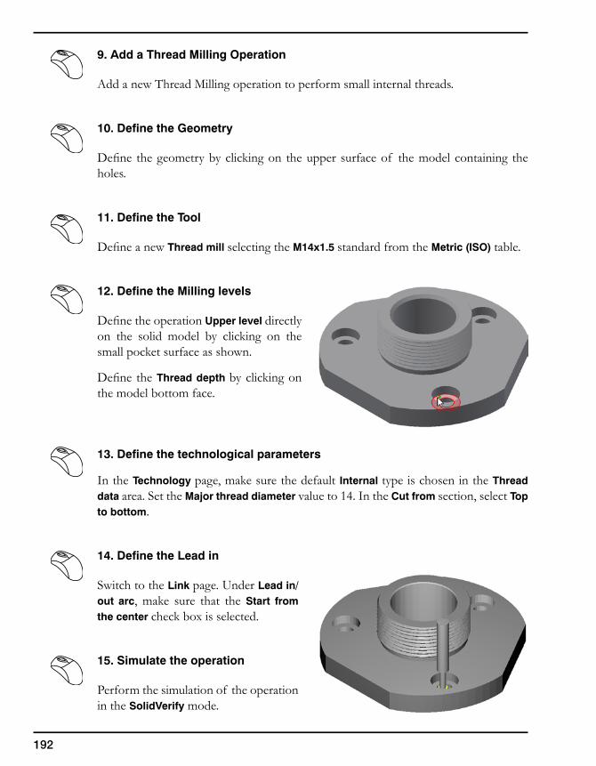
192
9. Add a Thread Milling Operation
Add a new Thread Milling operation to perform small internal threads.
10. Define the Geometry
Define the geometry by clicking on the upper surface of the model containing the holes.
11. Define the Tool
Define a new Thread mill selecting the M14x1.5 standard from the Metric (ISO) table.
12. Define the Milling levels
Define the operation Upper level directly on the solid model by clicking on the small pocket surface as shown.
Define the Thread depth by clicking on the model bottom face.
13. Define the technological parameters
In the Technology page, make sure the default Internal type is chosen in the Thread data area. Set the Major thread diameter value to 14. In the Cut from section, select Top to bottom.
14. Define the Lead in
Switch to the Link page. Under Lead in/out arc, make sure that the Start from the center check box is selected.
15. Simulate the operation
Perform the simulation of the operation in the SolidVerify mode.
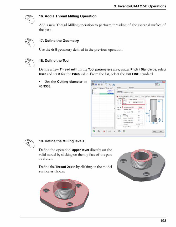
193
3. InventorCAM 2.5D Operations
16. Add a Thread Milling Operation
Add a new Thread Milling operation to perform threading of the external surface of the part.
17. Define the Geometry
Use the drill geometry defined in the previous operation.
18. Define the Tool
Define a new Thread mill. In the Tool parameters area, under Pitch / Standards, select User and set 3 for the Pitch value. From the list, select the ISO FINE standard.
• Set the Cutting diameter to 45.3333.
19. Define the Milling levels
Define the operation Upper level directly on the solid model by clicking on the top face of the part as shown.
Define the Thread Depth by clicking on the model surface as shown.
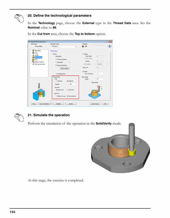
194
20. Define the technological parameters
In the Technology page, choose the External type in the Thread Data area. Set the Nominal value to 86.
In the Cut from area, choose the Top to bottom option.
21. Simulate the operation
Perform the simulation of the operation in the SolidVerify mode.
At this stage, the exercise is completed.

Indexial4-Axis Milling 4
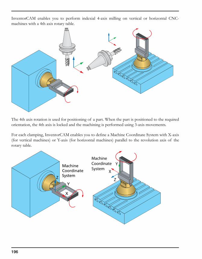
196
InventorCAM enables you to perform indexial 4-axis milling on vertical or horizontal CNC-machines with a 4th axis rotary table.
The 4th axis rotation is used for positioning of a part. When the part is positioned to the required orientation, the 4th axis is locked and the machining is performed using 3-axis movements.
For each clamping, InventorCAM enables you to define a Machine Coordinate System with X-axis (for vertical machines) or Y-axis (for horizontal machines) parallel to the revolution axis of the rotary table.
MachineCoordinateSystem
X
Y
Z
MachineCoordinateSystem
X
Y
Z
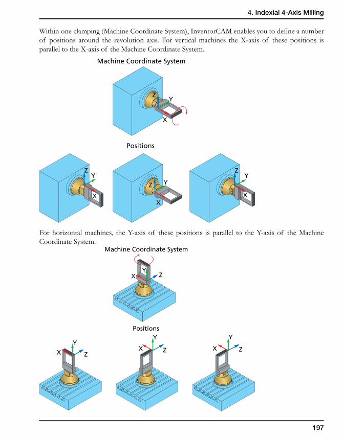
197
4. Indexial 4-Axis Milling
Within one clamping (Machine Coordinate System), InventorCAM enables you to define a number of positions around the revolution axis. For vertical machines the X-axis of these positions is parallel to the X-axis of the Machine Coordinate System.
For horizontal machines, the Y-axis of these positions is parallel to the Y-axis of the Machine Coordinate System.
X
YZ
X
YZ
X
YZ
X
YZ
Machine Coordinate System
Positions
Machine Coordinate System
Positions
XY
Z
XY
ZX
Y
Z X
Y
Z
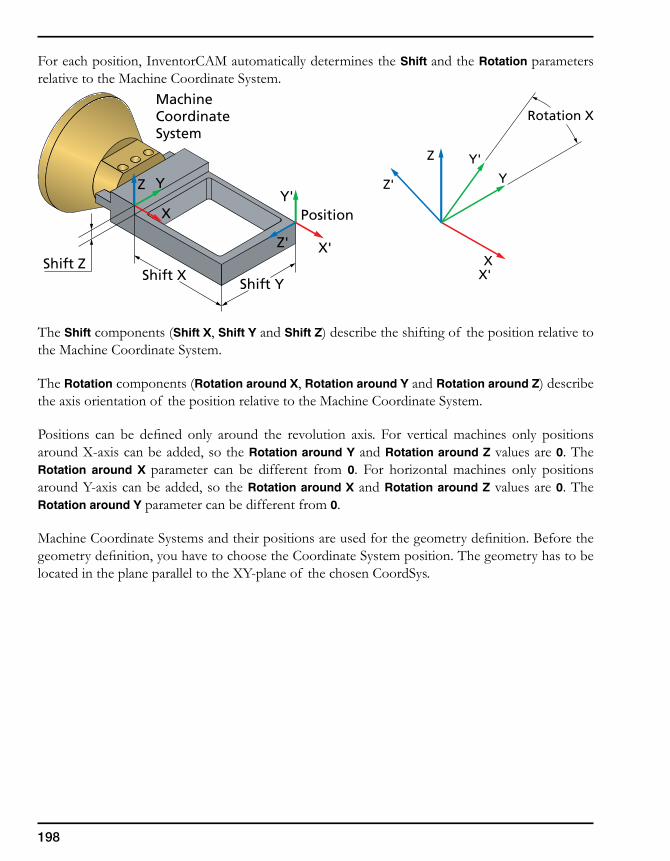
198
For each position, InventorCAM automatically determines the Shift and the Rotation parameters relative to the Machine Coordinate System.
The Shift components (Shift X, Shift Y and Shift Z) describe the shifting of the position relative to the Machine Coordinate System.
The Rotation components (Rotation around X, Rotation around Y and Rotation around Z) describe the axis orientation of the position relative to the Machine Coordinate System.
Positions can be defined only around the revolution axis. For vertical machines only positions around X-axis can be added, so the Rotation around Y and Rotation around Z values are 0. The Rotation around X parameter can be different from 0. For horizontal machines only positions around Y-axis can be added, so the Rotation around X and Rotation around Z values are 0. The Rotation around Y parameter can be different from 0.
Machine Coordinate Systems and their positions are used for the geometry definition. Before the geometry definition, you have to choose the Coordinate System position. The geometry has to be located in the plane parallel to the XY-plane of the chosen CoordSys.
MachineCoordinateSystem
X
YZ
Position
X'
Y'
Z'
Shift XShift Y
Shift Z X
Y
Z
X'
Y'
Rotation X
Z'
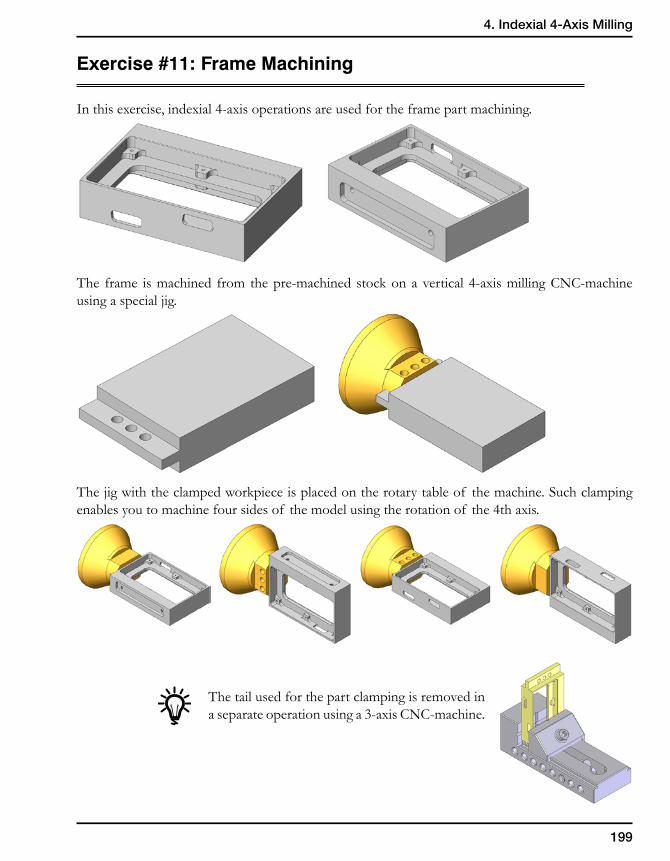
199
4. Indexial 4-Axis Milling
Exercise #11: Frame Machining
In this exercise, indexial 4-axis operations are used for the frame part machining.
The frame is machined from the pre-machined stock on a vertical 4-axis milling CNC-machine using a special jig.
The jig with the clamped workpiece is placed on the rotary table of the machine. Such clamping enables you to machine four sides of the model using the rotation of the 4th axis.
The tail used for the part clamping is removed in a separate operation using a 3-axis CNC-machine.
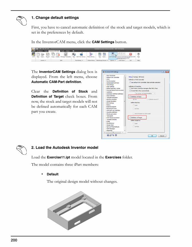
200
1. Change default settings
First, you have to cancel automatic definition of the stock and target models, which is set in the preferences by default.
In the InventorCAM menu, click the CAM Settings button.
The InventorCAM Settings dialog box is displayed. From the left menu, choose Automatic CAM-Part definition.
Clear the Definition of Stock and Definition of Target check boxes. From now, the stock and target models will not be defined automatically for each CAM part you create.
2. Load the Autodesk Inventor model
Load the Exercise11.ipt model located in the Exercises folder.
The model contains three iPart members:
• Default
The original design model without changes.
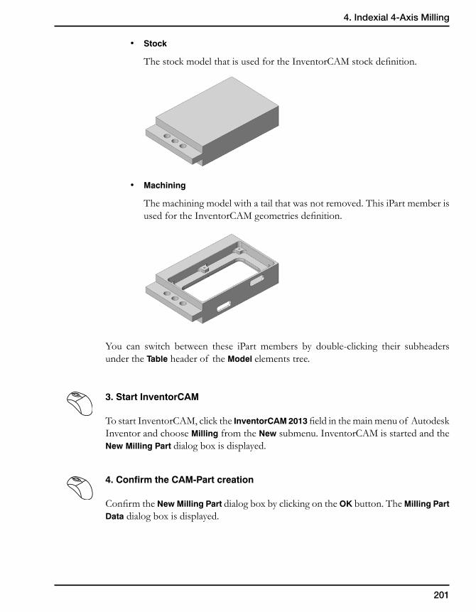
201
4. Indexial 4-Axis Milling
• Stock
The stock model that is used for the InventorCAM stock definition.
• Machining
The machining model with a tail that was not removed. This iPart member is used for the InventorCAM geometries definition.
You can switch between these iPart members by double-clicking their subheaders under the Table header of the Model elements tree.
3. Start InventorCAM
To start InventorCAM, click the InventorCAM 2013 field in the main menu of Autodesk Inventor and choose Milling from the New submenu. InventorCAM is started and the New Milling Part dialog box is displayed.
4. Confirm the CAM-Part creation
Confirm the New Milling Part dialog box by clicking on the OK button. The Milling Part Data dialog box is displayed.
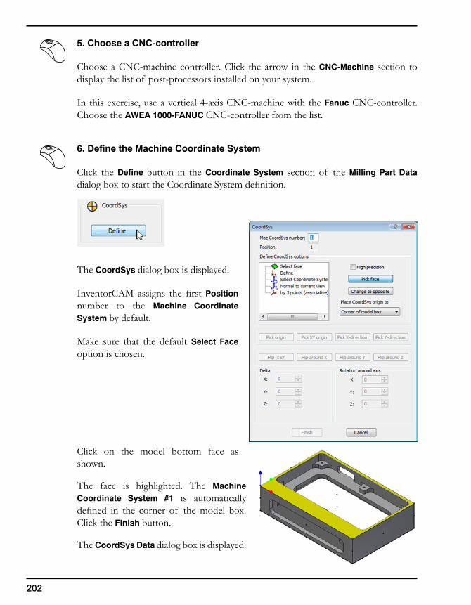
202
5. Choose a CNC-controller
Choose a CNC-machine controller. Click the arrow in the CNC-Machine section to display the list of post-processors installed on your system.
In this exercise, use a vertical 4-axis CNC-machine with the Fanuc CNC-controller. Choose the AWEA 1000-FANUC CNC-controller from the list.
6. Define the Machine Coordinate System
Click the Define button in the Coordinate System section of the Milling Part Data dialog box to start the Coordinate System definition.
The CoordSys dialog box is displayed.
InventorCAM assigns the first Position number to the Machine Coordinate System by default.
Make sure that the default Select Face option is chosen.
Click on the model bottom face as shown.
The face is highlighted. The Machine Coordinate System #1 is automatically defined in the corner of the model box. Click the Finish button.
The CoordSys Data dialog box is displayed.
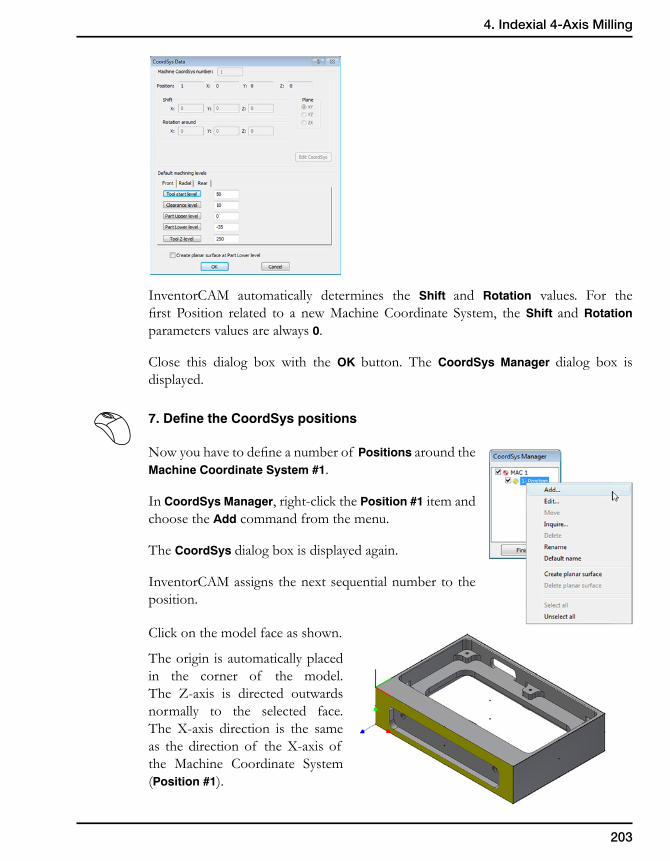
203
4. Indexial 4-Axis Milling
InventorCAM automatically determines the Shift and Rotation values. For the first Position related to a new Machine Coordinate System, the Shift and Rotation parameters values are always 0.
Close this dialog box with the OK button. The CoordSys Manager dialog box is displayed.
7. Define the CoordSys positions
Now you have to define a number of Positions around the Machine Coordinate System #1.
In CoordSys Manager, right-click the Position #1 item and choose the Add command from the menu.
The CoordSys dialog box is displayed again.
InventorCAM assigns the next sequential number to the position.
Click on the model face as shown.
The origin is automatically placed in the corner of the model. The Z-axis is directed outwards normally to the selected face. The X-axis direction is the same as the direction of the X-axis of the Machine Coordinate System (Position #1).
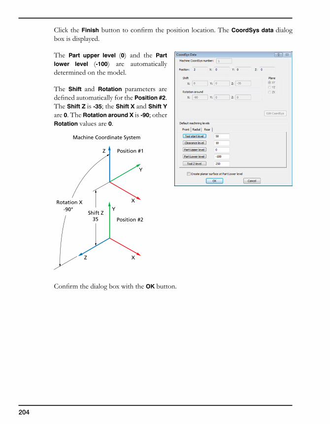
204
Click the Finish button to confirm the position location. The CoordSys data dialog box is displayed.
The Part upper level (0) and the Part lower level (-100) are automatically determined on the model.
The Shift and Rotation parameters are defined automatically for the Position #2. The Shift Z is -35; the Shift X and Shift Y are 0. The Rotation around X is -90; other Rotation values are 0.
Confirm the dialog box with the OK button.
X
Y
Z
X
Y
Z
Machine Coordinate System
Position #235
-90°Rotation X
Shift Z
Position #1
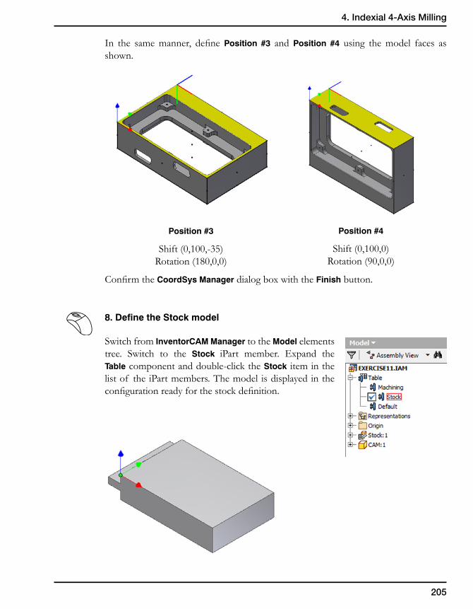
205
4. Indexial 4-Axis Milling
In the same manner, define Position #3 and Position #4 using the model faces as shown.
Position #3
Shift (0,100,-35)Rotation (180,0,0)
Position #4
Shift (0,100,0)Rotation (90,0,0)
Confirm the CoordSys Manager dialog box with the Finish button.
8. Define the Stock model
Switch from InventorCAM Manager to the Model elements tree. Switch to the Stock iPart member. Expand the Table component and double-click the Stock item in the list of the iPart members. The model is displayed in the configuration ready for the stock definition.
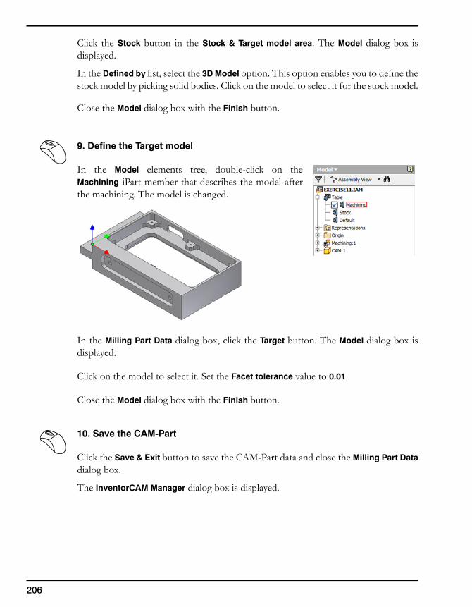
206
Click the Stock button in the Stock & Target model area. The Model dialog box is displayed.
In the Defined by list, select the 3D Model option. This option enables you to define the stock model by picking solid bodies. Click on the model to select it for the stock model.
Close the Model dialog box with the Finish button.
9. Define the Target model
In the Model elements tree, double-click on the Machining iPart member that describes the model after the machining. The model is changed.
In the Milling Part Data dialog box, click the Target button. The Model dialog box is displayed.
Click on the model to select it. Set the Facet tolerance value to 0.01.
Close the Model dialog box with the Finish button.
10. Save the CAM-Part
Click the Save & Exit button to save the CAM-Part data and close the Milling Part Data dialog box.
The InventorCAM Manager dialog box is displayed.
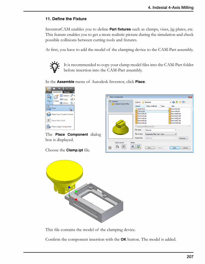
207
4. Indexial 4-Axis Milling
11. Define the Fixture
InventorCAM enables you to define Part fixtures such as clamps, vises, jig plates, etc. This feature enables you to get a more realistic picture during the simulation and check possible collisions between cutting tools and fixtures.
At first, you have to add the model of the clamping device to the CAM-Part assembly.
It is recommended to copy your clamp model files into the CAM-Part folder before insertion into the CAM-Part assembly.
In the Assemble menu of Autodesk Inventor, click Place.
The Place Component dialog box is displayed.
Choose the Clamp.ipt file.
This file contains the model of the clamping device.
Confirm the component insertion with the OK button. The model is added.
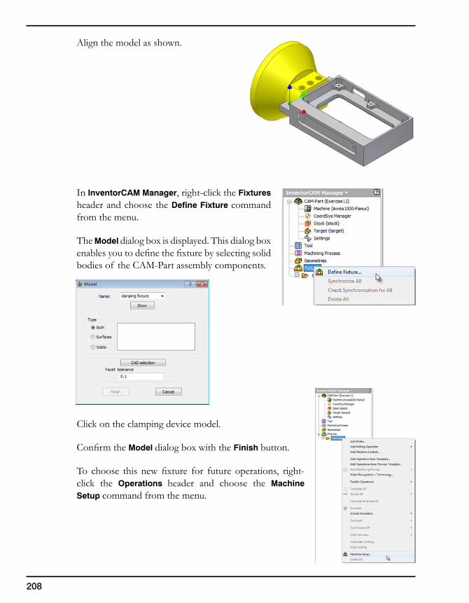
208
Align the model as shown.
In InventorCAM Manager, right-click the Fixtures header and choose the Define Fixture command from the menu.
The Model dialog box is displayed. This dialog box enables you to define the fixture by selecting solid bodies of the CAM-Part assembly components.
Click on the clamping device model.
Confirm the Model dialog box with the Finish button.
To choose this new fixture for future operations, right-click the Operations header and choose the Machine Setup command from the menu.
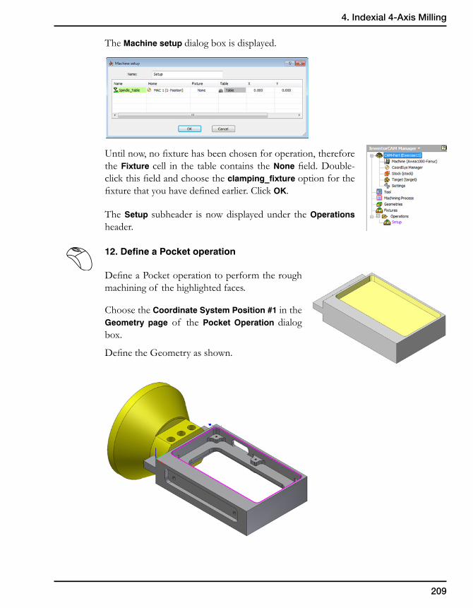
209
4. Indexial 4-Axis Milling
The Machine setup dialog box is displayed.
Until now, no fixture has been chosen for operation, therefore the Fixture cell in the table contains the None field. Double-click this field and choose the clamping_fixture option for the fixture that you have defined earlier. Click OK.
The Setup subheader is now displayed under the Operations header.
12. Define a Pocket operation
Define a Pocket operation to perform the rough machining of the highlighted faces.
Choose the Coordinate System Position #1 in the Geometry page of the Pocket Operation dialog box.
Define the Geometry as shown.
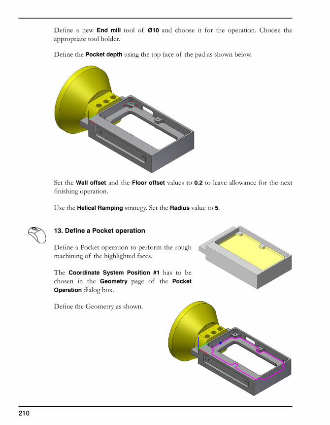
210
Define a new End mill tool of Ø10 and choose it for the operation. Choose the appropriate tool holder.
Define the Pocket depth using the top face of the pad as shown below.
Set the Wall offset and the Floor offset values to 0.2 to leave allowance for the next finishing operation.
Use the Helical Ramping strategy. Set the Radius value to 5.
13. Define a Pocket operation
Define a Pocket operation to perform the rough machining of the highlighted faces.
The Coordinate System Position #1 has to be chosen in the Geometry page of the Pocket Operation dialog box.
Define the Geometry as shown.
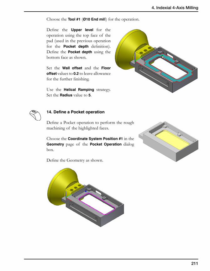
211
4. Indexial 4-Axis Milling
Choose the Tool #1 (Ø10 End mill) for the operation.
Define the Upper level for the operation using the top face of the pad (used in the previous operation for the Pocket depth definition). Define the Pocket depth using the bottom face as shown.
Set the Wall offset and the Floor offset values to 0.2 to leave allowance for the further finishing.
Use the Helical Ramping strategy. Set the Radius value to 5.
14. Define a Pocket operation
Define a Pocket operation to perform the rough machining of the highlighted faces.
Choose the Coordinate System Position #1 in the Geometry page of the Pocket Operation dialog box.
Define the Geometry as shown.
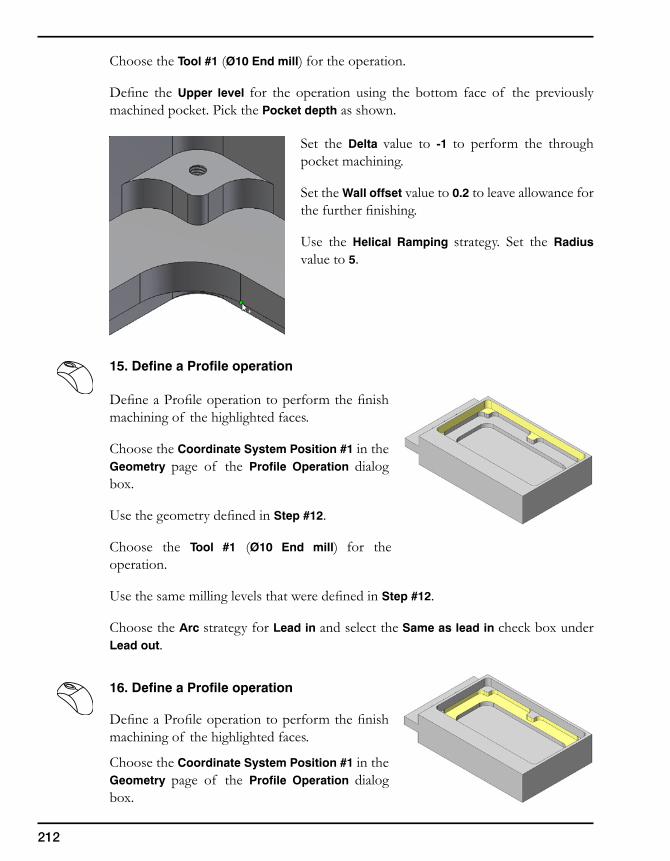
212
Choose the Tool #1 (Ø10 End mill) for the operation.
Define the Upper level for the operation using the bottom face of the previously machined pocket. Pick the Pocket depth as shown.
Set the Delta value to -1 to perform the through pocket machining.
Set the Wall offset value to 0.2 to leave allowance for the further finishing.
Use the Helical Ramping strategy. Set the Radius value to 5.
15. Define a Profile operation
Define a Profile operation to perform the finish machining of the highlighted faces.
Choose the Coordinate System Position #1 in the Geometry page of the Profile Operation dialog box.
Use the geometry defined in Step #12.
Choose the Tool #1 (Ø10 End mill) for the operation.
Use the same milling levels that were defined in Step #12.
Choose the Arc strategy for Lead in and select the Same as lead in check box under Lead out.
16. Define a Profile operation
Define a Profile operation to perform the finish machining of the highlighted faces.
Choose the Coordinate System Position #1 in the Geometry page of the Profile Operation dialog box.
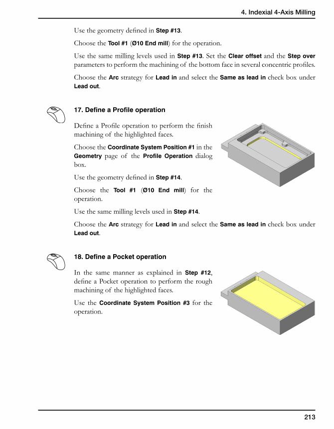
213
4. Indexial 4-Axis Milling
Use the geometry defined in Step #13.
Choose the Tool #1 (Ø10 End mill) for the operation.
Use the same milling levels used in Step #13. Set the Clear offset and the Step over parameters to perform the machining of the bottom face in several concentric profiles.
Choose the Arc strategy for Lead in and select the Same as lead in check box under Lead out.
17. Define a Profile operation
Define a Profile operation to perform the finish machining of the highlighted faces.
Choose the Coordinate System Position #1 in the Geometry page of the Profile Operation dialog box.
Use the geometry defined in Step #14.
Choose the Tool #1 (Ø10 End mill) for the operation.
Use the same milling levels used in Step #14.
Choose the Arc strategy for Lead in and select the Same as lead in check box under Lead out.
18. Define a Pocket operation
In the same manner as explained in Step #12, define a Pocket operation to perform the rough machining of the highlighted faces.
Use the Coordinate System Position #3 for the operation.
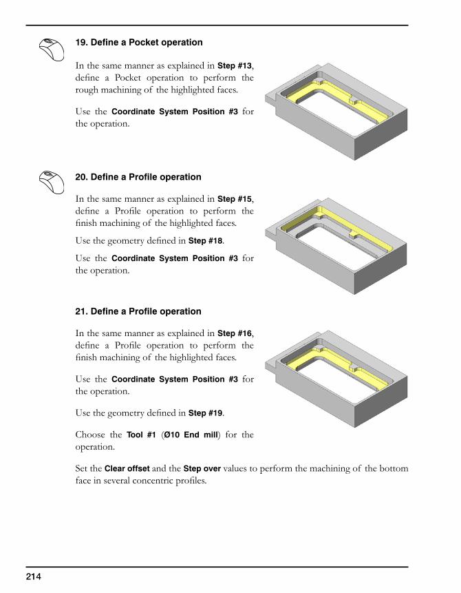
214
19. Define a Pocket operation
In the same manner as explained in Step #13, define a Pocket operation to perform the rough machining of the highlighted faces.
Use the Coordinate System Position #3 for the operation.
20. Define a Profile operation
In the same manner as explained in Step #15, define a Profile operation to perform the finish machining of the highlighted faces.
Use the geometry defined in Step #18.
Use the Coordinate System Position #3 for the operation.
21. Define a Profile operation
In the same manner as explained in Step #16, define a Profile operation to perform the finish machining of the highlighted faces.
Use the Coordinate System Position #3 for the operation.
Use the geometry defined in Step #19.
Choose the Tool #1 (Ø10 End mill) for the operation.
Set the Clear offset and the Step over values to perform the machining of the bottom face in several concentric profiles.
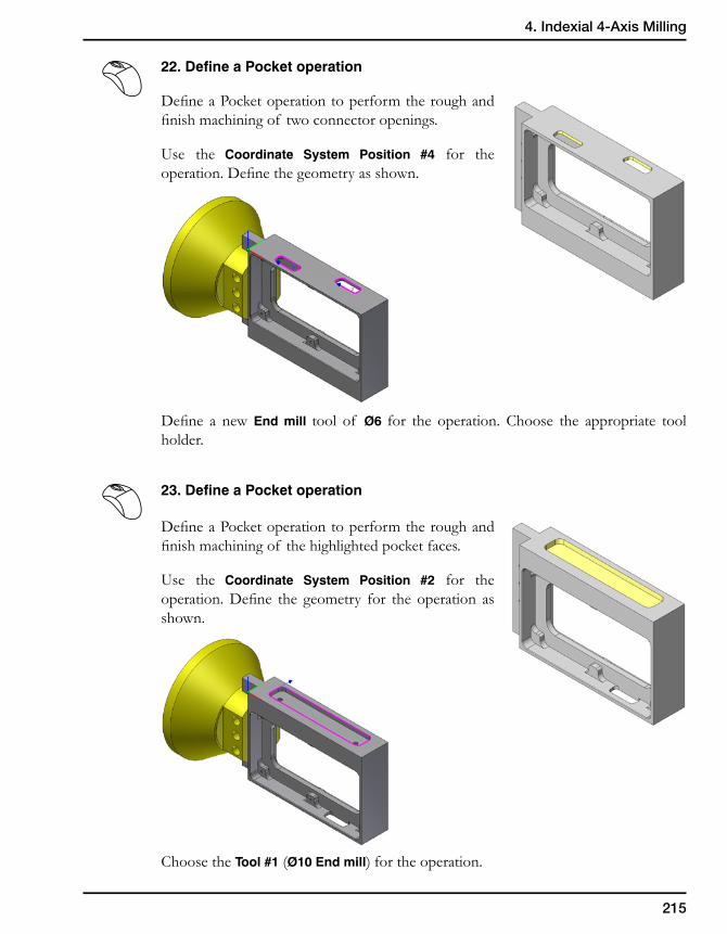
215
4. Indexial 4-Axis Milling
22. Define a Pocket operation
Define a Pocket operation to perform the rough and finish machining of two connector openings.
Use the Coordinate System Position #4 for the operation. Define the geometry as shown.
Define a new End mill tool of Ø6 for the operation. Choose the appropriate tool holder.
23. Define a Pocket operation
Define a Pocket operation to perform the rough and finish machining of the highlighted pocket faces.
Use the Coordinate System Position #2 for the operation. Define the geometry for the operation as shown.
Choose the Tool #1 (Ø10 End mill) for the operation.
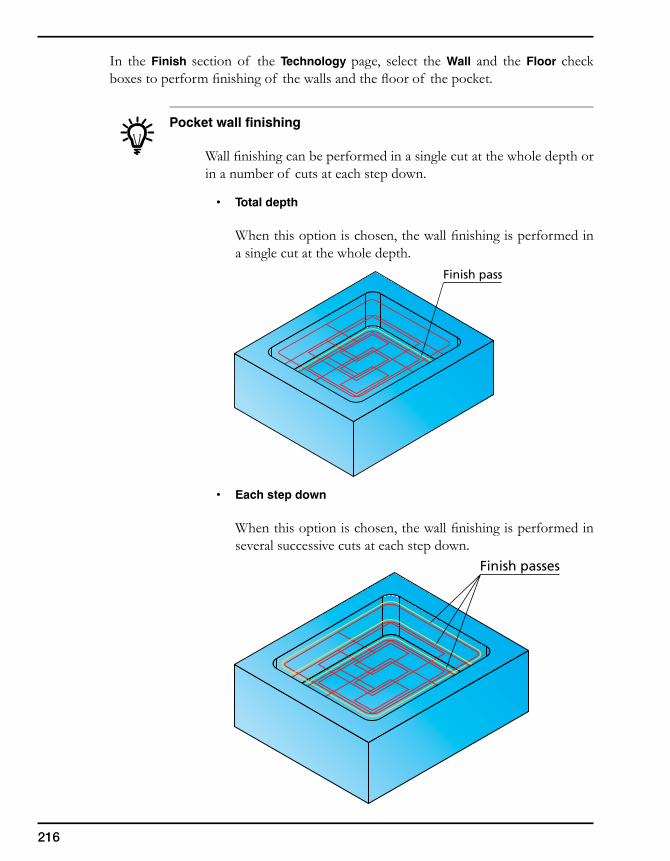
216
In the Finish section of the Technology page, select the Wall and the Floor check boxes to perform finishing of the walls and the floor of the pocket.
Pocket wall finishing
Wall finishing can be performed in a single cut at the whole depth or in a number of cuts at each step down.
• Totaldepth
When this option is chosen, the wall finishing is performed in a single cut at the whole depth.
• Eachstepdown
When this option is chosen, the wall finishing is performed in several successive cuts at each step down.
Finish passes
Finish pass
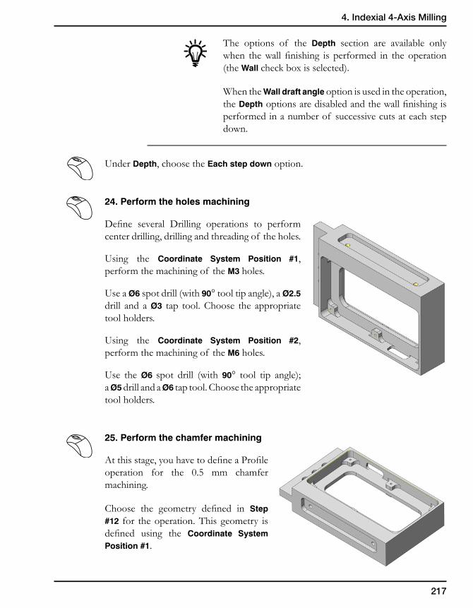
217
4. Indexial 4-Axis Milling
The options of the Depth section are available only when the wall finishing is performed in the operation (the Wall check box is selected).
When the Wall draft angle option is used in the operation, the Depth options are disabled and the wall finishing is performed in a number of successive cuts at each step down.
Under Depth, choose the Each step down option.
24. Perform the holes machining
Define several Drilling operations to perform center drilling, drilling and threading of the holes.
Using the Coordinate System Position #1, perform the machining of the M3 holes.
Use a Ø6 spot drill (with 90° tool tip angle), a Ø2.5 drill and a Ø3 tap tool. Choose the appropriate tool holders.
Using the Coordinate System Position #2, perform the machining of the M6 holes.
Use the Ø6 spot drill (with 90° tool tip angle); a Ø5 drill and a Ø6 tap tool. Choose the appropriate tool holders.
25. Perform the chamfer machining
At this stage, you have to define a Profile operation for the 0.5 mm chamfer machining.
Choose the geometry defined in Step #12 for the operation. This geometry is defined using the Coordinate System Position #1.
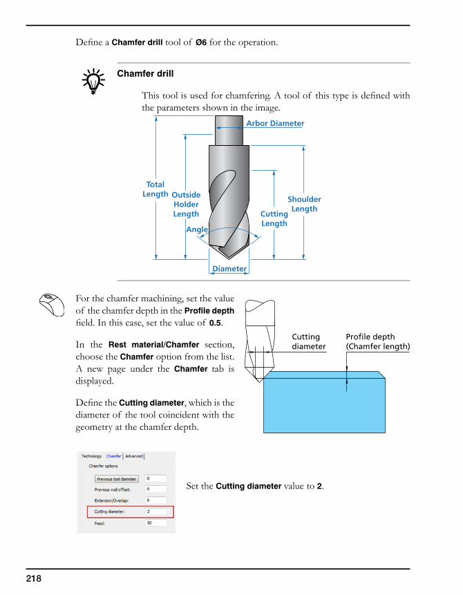
218
Define a Chamfer drill tool of Ø6 for the operation.
Chamfer drill
This tool is used for chamfering. A tool of this type is defined with the parameters shown in the image.
For the chamfer machining, set the value of the chamfer depth in the Profile depth field. In this case, set the value of 0.5.
In the Rest material/Chamfer section, choose the Chamfer option from the list. A new page under the Chamfer tab is displayed.
Define the Cutting diameter, which is the diameter of the tool coincident with the geometry at the chamfer depth.
Set the Cutting diameter value to 2.
Cuttingdiameter
Profile depth(Chamfer length)
OutsideHolderLength Cutting
Length
Arbor Diameter
Diameter
TotalLength
ShoulderLength
Angle
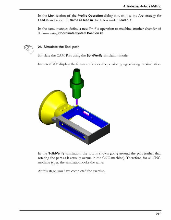
219
4. Indexial 4-Axis Milling
In the Link section of the Profile Operation dialog box, choose the Arc strategy for Lead in and select the Same as lead in check box under Lead out.
In the same manner, define a new Profile operation to machine another chamfer of 0.5 mm using Coordinate System Position #3.
26. Simulate the Tool path
Simulate the CAM-Part using the SolidVerify simulation mode.
InventorCAM displays the fixture and checks the possible gouges during the simulation.
In the SolidVerify simulation, the tool is shown going around the part (rather than rotating the part as it actually occurs in the CNC-machine). Therefore, for all CNC-machine types, the simulation looks the same.
At this stage, you have completed the exercise.
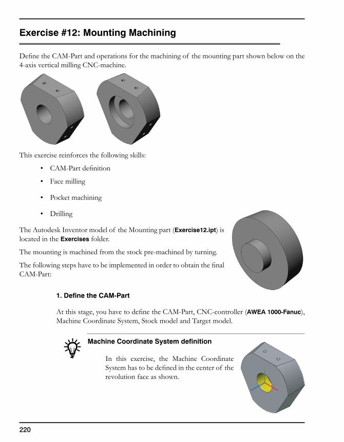
220
Exercise #12: Mounting Machining
Define the CAM-Part and operations for the machining of the mounting part shown below on the 4-axis vertical milling CNC-machine.
This exercise reinforces the following skills:
• CAM-Part definition
• Face milling
• Pocket machining
• Drilling
The Autodesk Inventor model of the Mounting part (Exercise12.ipt) is located in the Exercises folder.
The mounting is machined from the stock pre-machined by turning.
The following steps have to be implemented in order to obtain the final CAM-Part:
1. Define the CAM-Part
At this stage, you have to define the CAM-Part, CNC-controller (AWEA 1000-Fanuc), Machine Coordinate System, Stock model and Target model.
Machine Coordinate System definition
In this exercise, the Machine Coordinate System has to be defined in the center of the revolution face as shown.
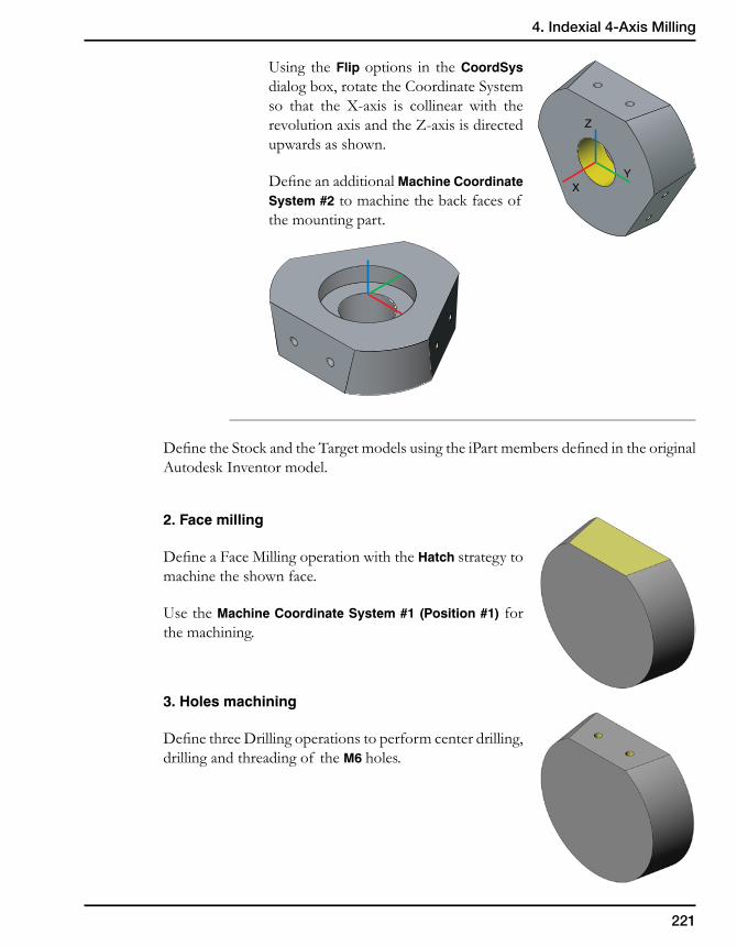
221
4. Indexial 4-Axis Milling
Using the Flip options in the CoordSys dialog box, rotate the Coordinate System so that the X-axis is collinear with the revolution axis and the Z-axis is directed upwards as shown.
Define an additional Machine Coordinate System #2 to machine the back faces of the mounting part.
Define the Stock and the Target models using the iPart members defined in the original Autodesk Inventor model.
2. Face milling
Define a Face Milling operation with the Hatch strategy to machine the shown face.
Use the Machine Coordinate System #1 (Position #1) for the machining.
3. Holes machining
Define three Drilling operations to perform center drilling, drilling and threading of the M6 holes.
XY
Z
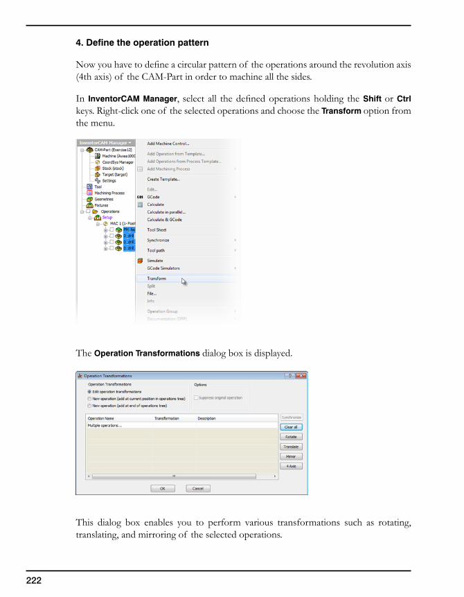
222
4. Define the operation pattern
Now you have to define a circular pattern of the operations around the revolution axis (4th axis) of the CAM-Part in order to machine all the sides.
In InventorCAM Manager, select all the defined operations holding the Shift or Ctrl keys. Right-click one of the selected operations and choose the Transform option from the menu.
The Operation Transformations dialog box is displayed.
This dialog box enables you to perform various transformations such as rotating, translating, and mirroring of the selected operations.
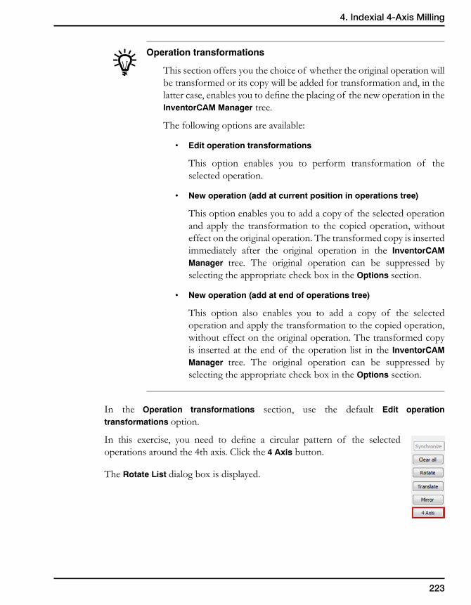
223
4. Indexial 4-Axis Milling
Operation transformations
This section offers you the choice of whether the original operation will be transformed or its copy will be added for transformation and, in the latter case, enables you to define the placing of the new operation in the InventorCAM Manager tree.
The following options are available:
• Editoperationtransformations
This option enables you to perform transformation of the selected operation.
• Newoperation(addatcurrentpositioninoperationstree)
This option enables you to add a copy of the selected operation and apply the transformation to the copied operation, without effect on the original operation. The transformed copy is inserted immediately after the original operation in the InventorCAM Manager tree. The original operation can be suppressed by selecting the appropriate check box in the Options section.
• Newoperation(addatendofoperationstree)
This option also enables you to add a copy of the selected operation and apply the transformation to the copied operation, without effect on the original operation. The transformed copy is inserted at the end of the operation list in the InventorCAM Manager tree. The original operation can be suppressed by selecting the appropriate check box in the Options section.
In the Operation transformations section, use the default Edit operation transformations option.
In this exercise, you need to define a circular pattern of the selected operations around the 4th axis. Click the 4 Axis button.
The Rotate List dialog box is displayed.
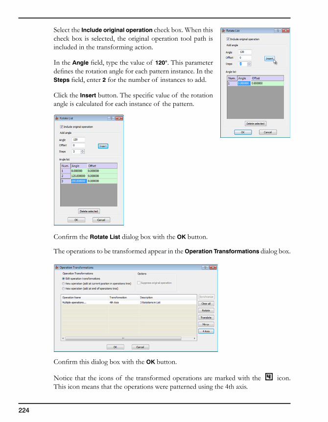
224
Select the Include original operation check box. When this check box is selected, the original operation tool path is included in the transforming action.
In the Angle field, type the value of 120°. This parameter defines the rotation angle for each pattern instance. In the Steps field, enter 2 for the number of instances to add.
Click the Insert button. The specific value of the rotation angle is calculated for each instance of the pattern.
Confirm the Rotate List dialog box with the OK button.
The operations to be transformed appear in the Operation Transformations dialog box.
Confirm this dialog box with the OK button.
Notice that the icons of the transformed operations are marked with the icon. This icon means that the operations were patterned using the 4th axis.
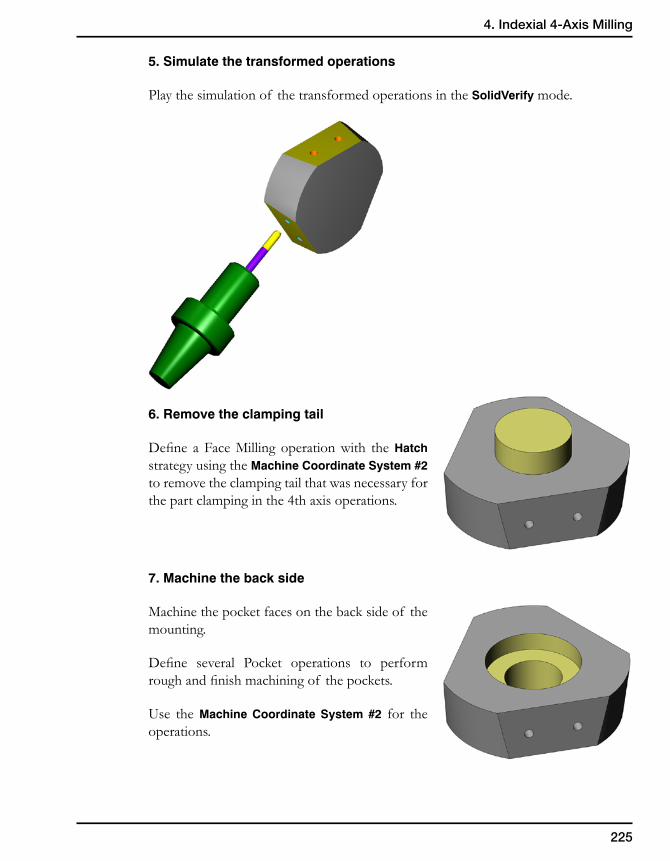
225
4. Indexial 4-Axis Milling
5. Simulate the transformed operations
Play the simulation of the transformed operations in the SolidVerify mode.
6. Remove the clamping tail
Define a Face Milling operation with the Hatch strategy using the Machine Coordinate System #2 to remove the clamping tail that was necessary for the part clamping in the 4th axis operations.
7. Machine the back side
Machine the pocket faces on the back side of the mounting.
Define several Pocket operations to perform rough and finish machining of the pockets.
Use the Machine Coordinate System #2 for the operations.

226

Indexial5-Axis Milling 5
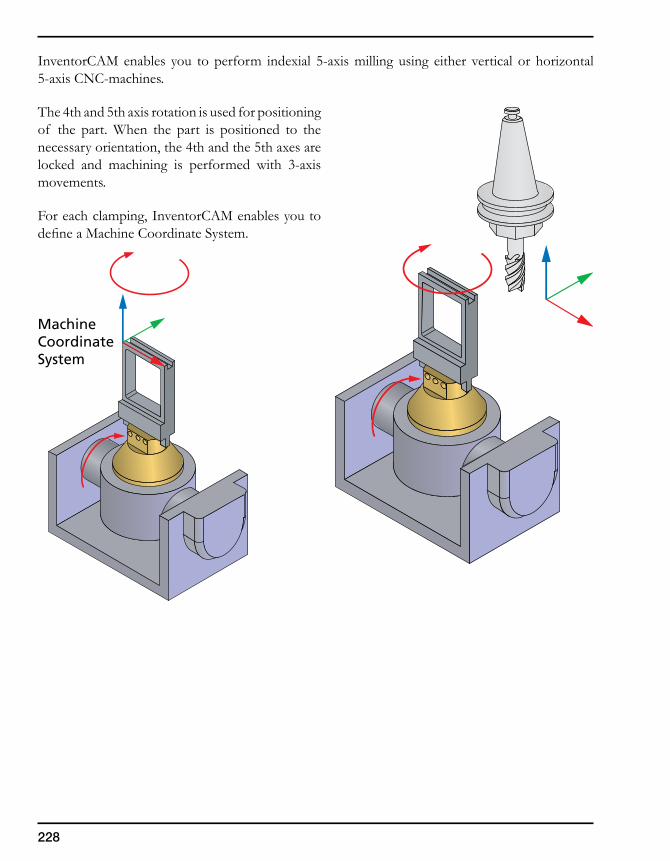
228
InventorCAM enables you to perform indexial 5-axis milling using either vertical or horizontal 5-axis CNC-machines.
The 4th and 5th axis rotation is used for positioning of the part. When the part is positioned to the necessary orientation, the 4th and the 5th axes are locked and machining is performed with 3-axis movements.
For each clamping, InventorCAM enables you to define a Machine Coordinate System.
MachineCoordinateSystem
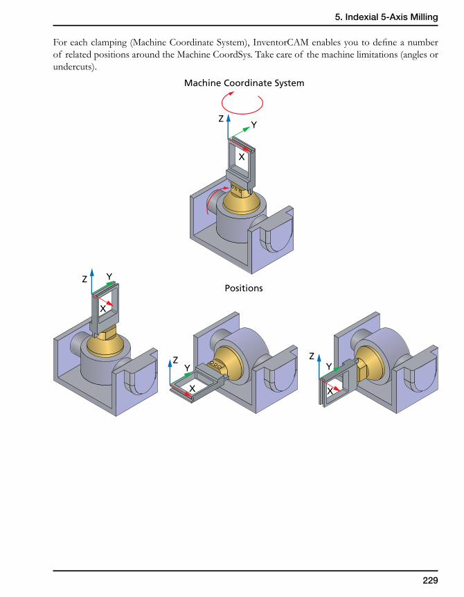
229
5. Indexial 5-Axis Milling
For each clamping (Machine Coordinate System), InventorCAM enables you to define a number of related positions around the Machine CoordSys. Take care of the machine limitations (angles or undercuts).
Machine Coordinate System
Positions
ZY
X
Z Y
X
ZY
X
ZY
X
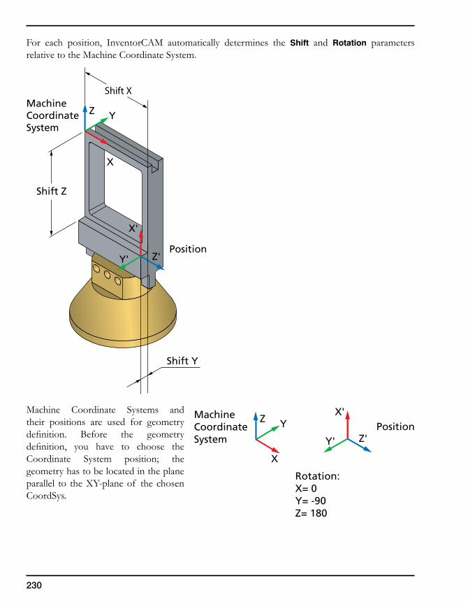
230
For each position, InventorCAM automatically determines the Shift and Rotation parameters relative to the Machine Coordinate System.
Machine Coordinate Systems and their positions are used for geometry definition. Before the geometry definition, you have to choose the Coordinate System position; the geometry has to be located in the plane parallel to the XY-plane of the chosen CoordSys.
MachineCoordinateSystem
Position
Shift X
Shift Y
Shift Z
X
YZ
Y'
X'
Z'
MachineCoordinateSystem
Position
Rotation:X= 0Y= -90Z= 180
X
YZ
Y'
X'
Z'
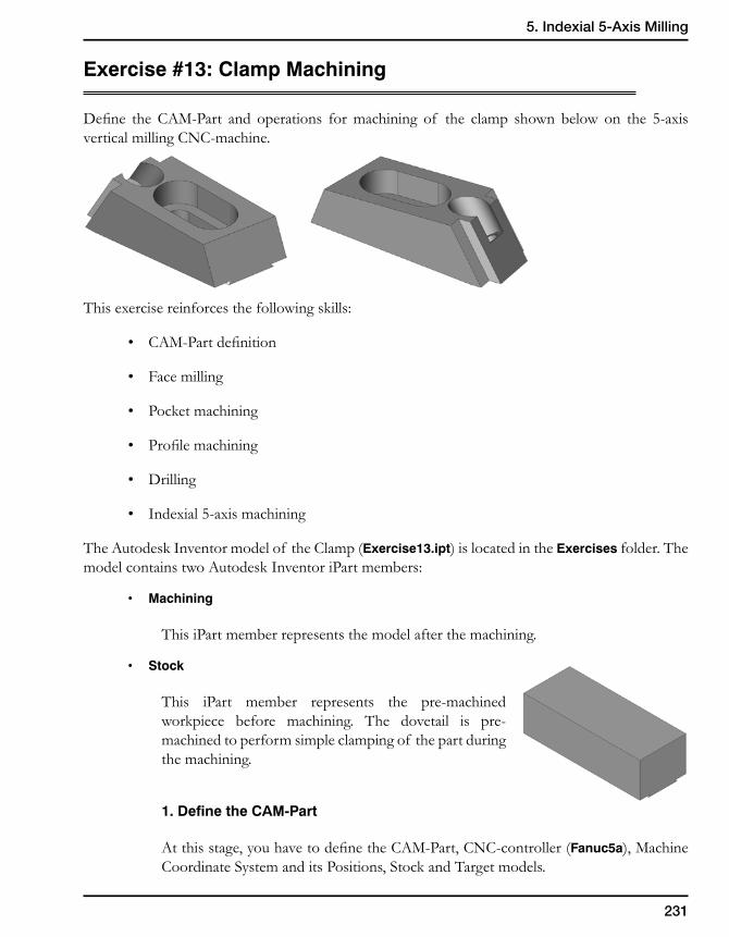
231
5. Indexial 5-Axis Milling
Exercise #13: Clamp Machining
Define the CAM-Part and operations for machining of the clamp shown below on the 5-axis vertical milling CNC-machine.
This exercise reinforces the following skills:
• CAM-Part definition
• Face milling
• Pocket machining
• Profile machining
• Drilling
• Indexial 5-axis machining
The Autodesk Inventor model of the Clamp (Exercise13.ipt) is located in the Exercises folder. The model contains two Autodesk Inventor iPart members:
• Machining
This iPart member represents the model after the machining.
• Stock
This iPart member represents the pre-machined workpiece before machining. The dovetail is pre-machined to perform simple clamping of the part during the machining.
1. Define the CAM-Part
At this stage, you have to define the CAM-Part, CNC-controller (Fanuc5a), Machine Coordinate System and its Positions, Stock and Target models.
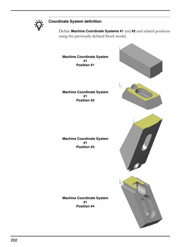
232
Coordinate System definition
Define Machine Coordinate Systems #1 and #2 and related positions using the previously defined Stock model.
Machine Coordinate System #1
Position #1
Machine Coordinate System #1
Position #2
Machine Coordinate System #1
Position #3
Machine Coordinate System #1
Position #4
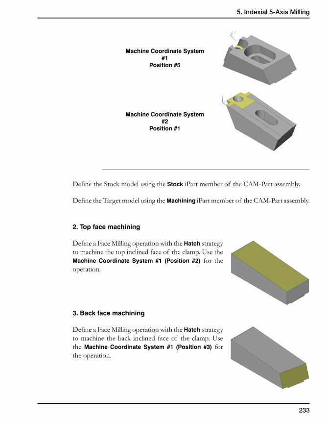
233
5. Indexial 5-Axis Milling
Machine Coordinate System #1
Position #5
Machine Coordinate System #2
Position #1
Define the Stock model using theStockiPart member of the CAM-Part assembly.
Define the Target model using the Machining iPart member of the CAM-Part assembly.
2. Top face machining
Define a Face Milling operation with the Hatch strategy to machine the top inclined face of the clamp. Use the Machine Coordinate System #1 (Position #2) for the operation.
3.Backfacemachining
Define a Face Milling operation with the Hatch strategy to machine the back inclined face of the clamp. Use the Machine Coordinate System #1 (Position #3) for the operation.
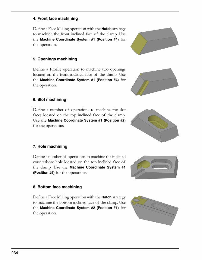
234
4. Front face machining
Define a Face Milling operation with the Hatch strategy to machine the front inclined face of the clamp. Use the Machine Coordinate System #1 (Position #4) for the operation.
5. Openings machining
Define a Profile operation to machine two openings located on the front inclined face of the clamp. Use the Machine Coordinate System #1 (Position #4) for the operation.
6. Slot machining
Define a number of operations to machine the slot faces located on the top inclined face of the clamp. Use the Machine Coordinate System #1 (Position #2) for the operations.
7. Hole machining
Define a number of operations to machine the inclined counterbore hole located on the top inclined face of the clamp. Use the Machine Coordinate System #1 (Position #5) for the operations.
8. Bottom face machining
Define a Face Milling operation with the Hatch strategy to machine the bottom inclined face of the clamp. Use the Machine Coordinate System #2 (Position #1) for the operation.

ToolBox 6
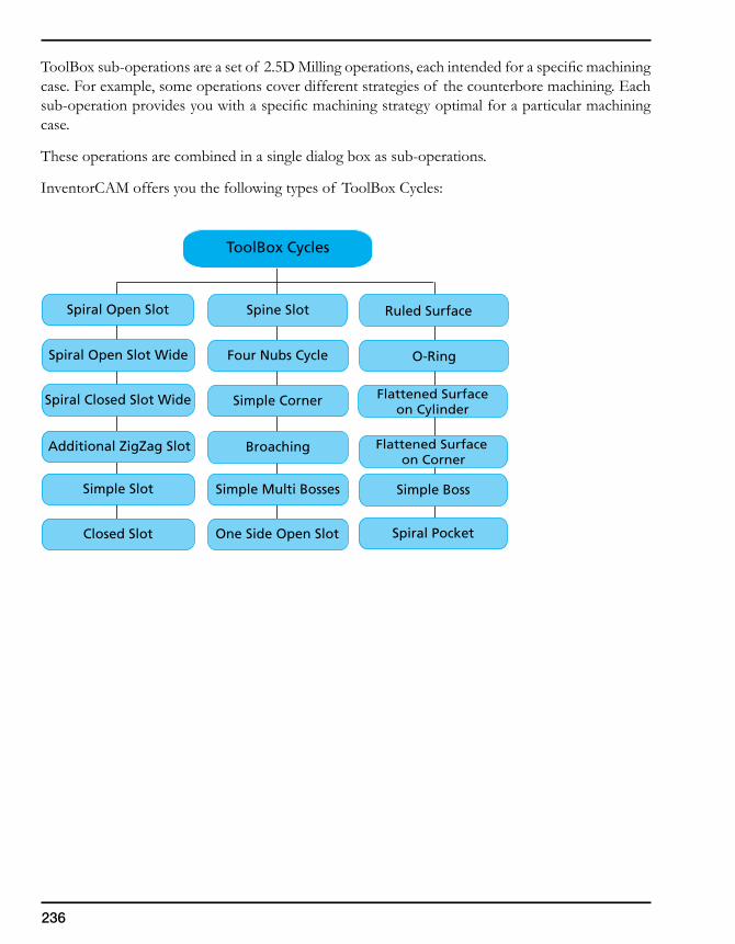
236
ToolBox sub-operations are a set of 2.5D Milling operations, each intended for a specific machining case. For example, some operations cover different strategies of the counterbore machining. Each sub-operation provides you with a specific machining strategy optimal for a particular machining case.
These operations are combined in a single dialog box as sub-operations.
InventorCAM offers you the following types of ToolBox Cycles:
ToolBox Cycles
Simple Slot
Closed Slot
Spiral Open Slot
Additional ZigZag Slot
Spiral Closed Slot Wide
Spiral Open Slot Wide
Simple Multi Bosses
One Side Open Slot
Spine Slot
Broaching
Simple Corner
Four Nubs Cycle
Simple Boss
Spiral Pocket
Ruled Surface
Flattened Surface on Corner
Flattened Surfaceon Cylinder
O-Ring
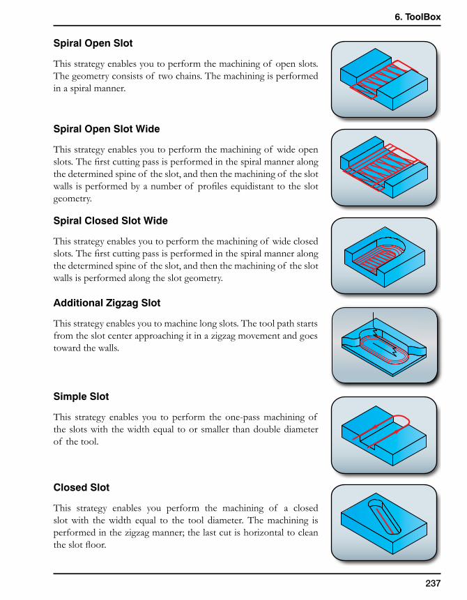
237
6. ToolBox
Spiral Open Slot
This strategy enables you to perform the machining of open slots. The geometry consists of two chains. The machining is performed in a spiral manner.
Spiral Open Slot Wide
This strategy enables you to perform the machining of wide open slots. The first cutting pass is performed in the spiral manner along the determined spine of the slot, and then the machining of the slot walls is performed by a number of profiles equidistant to the slot geometry.
Spiral Closed Slot Wide
This strategy enables you to perform the machining of wide closed slots. The first cutting pass is performed in the spiral manner along the determined spine of the slot, and then the machining of the slot walls is performed along the slot geometry.
Additional Zigzag Slot
This strategy enables you to machine long slots. The tool path starts from the slot center approaching it in a zigzag movement and goes toward the walls.
Simple Slot
This strategy enables you to perform the one-pass machining of the slots with the width equal to or smaller than double diameter of the tool.
Closed Slot
This strategy enables you perform the machining of a closed slot with the width equal to the tool diameter. The machining is performed in the zigzag manner; the last cut is horizontal to clean the slot floor.
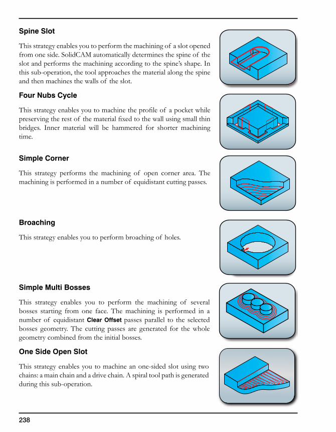
238
Spine Slot
This strategy enables you to perform the machining of a slot opened from one side. SolidCAM automatically determines the spine of the slot and performs the machining according to the spine’s shape. In this sub-operation, the tool approaches the material along the spine and then machines the walls of the slot.
Four Nubs Cycle
This strategy enables you to machine the profile of a pocket while preserving the rest of the material fixed to the wall using small thin bridges. Inner material will be hammered for shorter machining time.
Simple Corner
This strategy performs the machining of open corner area. The machining is performed in a number of equidistant cutting passes.
Broaching
This strategy enables you to perform broaching of holes.
Simple Multi Bosses
This strategy enables you to perform the machining of several bosses starting from one face. The machining is performed in a number of equidistant Clear Offset passes parallel to the selected bosses geometry. The cutting passes are generated for the whole geometry combined from the initial bosses.
One Side Open Slot
This strategy enables you to machine an one-sided slot using two chains: a main chain and a drive chain. A spiral tool path is generated during this sub-operation.
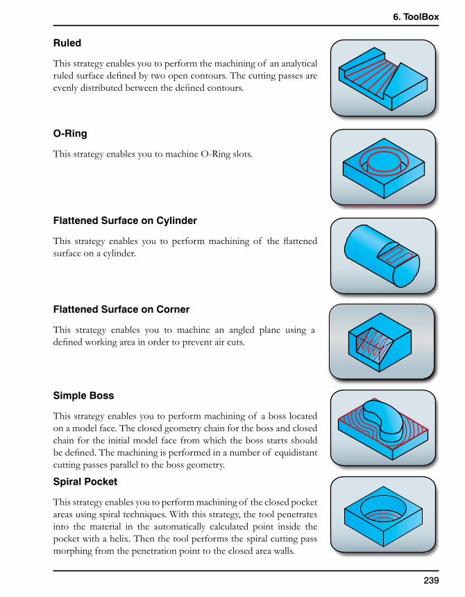
239
6. ToolBox
Ruled
This strategy enables you to perform the machining of an analytical ruled surface defined by two open contours. The cutting passes are evenly distributed between the defined contours.
O-Ring
This strategy enables you to machine O-Ring slots.
Flattened Surface on Cylinder
This strategy enables you to perform machining of the flattened surface on a cylinder.
Flattened Surface on Corner
This strategy enables you to machine an angled plane using a defined working area in order to prevent air cuts.
Simple Boss
This strategy enables you to perform machining of a boss located on a model face. The closed geometry chain for the boss and closed chain for the initial model face from which the boss starts should be defined. The machining is performed in a number of equidistant cutting passes parallel to the boss geometry.
Spiral Pocket
This strategy enables you to perform machining of the closed pocket areas using spiral techniques. With this strategy, the tool penetrates into the material in the automatically calculated point inside the pocket with a helix. Then the tool performs the spiral cutting pass morphing from the penetration point to the closed area walls.
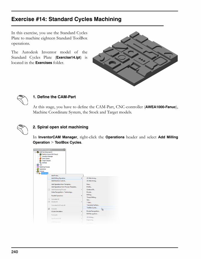
240
Exercise #14: Standard Cycles Machining
In this exercise, you use the Standard Cycles Plate to machine eighteen Standard ToolBox operations.
The Autodesk Inventor model of the Standard Cycles Plate (Exercise14.ipt) is located in the Exercises folder.
1. Define the CAM-Part
At this stage, you have to define the CAM-Part, CNC-controller (AWEA1000-Fanuc), Machine Coordinate System, the Stock and Target models.
2. Spiral open slot machining
In InventorCAM Manager, right-click the Operations header and select Add Milling Operation > ToolBox Cycles.
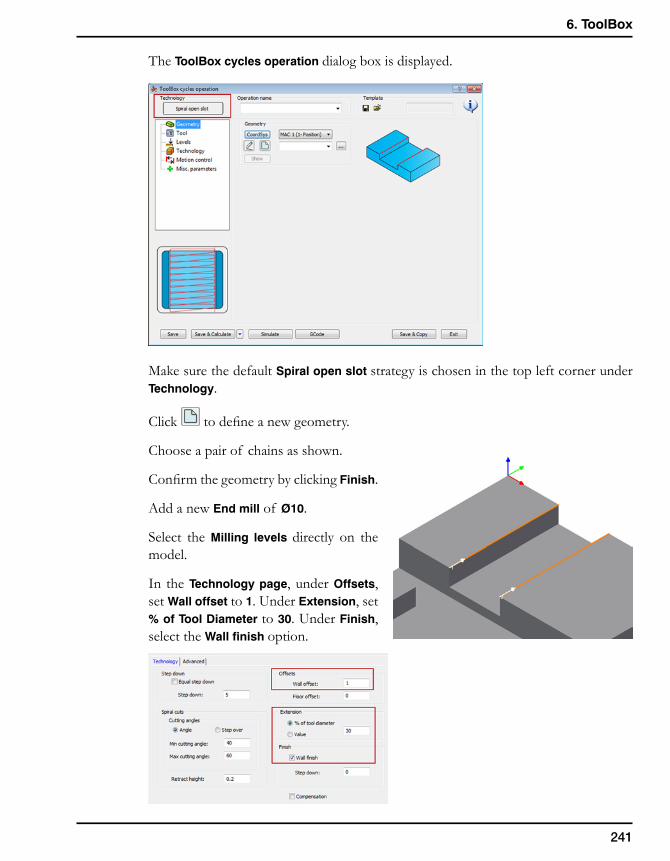
241
6. ToolBox
The ToolBox cycles operation dialog box is displayed.
Make sure the default Spiral open slot strategy is chosen in the top left corner under Technology.
Click to define a new geometry.
Choose a pair of chains as shown.
Confirm the geometry by clicking Finish.
Add a new End mill of Ø10.
Select the Milling levels directly on the model.
In the Technology page, under Offsets, set Wall offset to 1. Under Extension, set % of Tool Diameter to 30. Under Finish, select the Wall finish option.
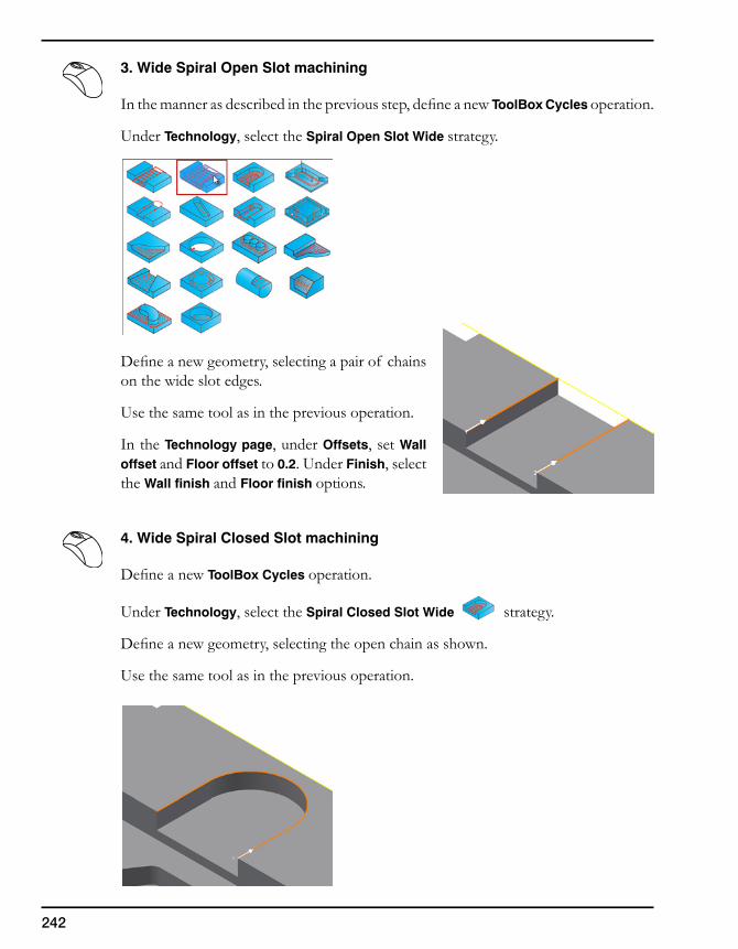
242
3. Wide Spiral Open Slot machining
In the manner as described in the previous step, define a new ToolBox Cycles operation.
Under Technology, select the Spiral Open Slot Wide strategy.
Define a new geometry, selecting a pair of chains on the wide slot edges.
Use the same tool as in the previous operation.
In the Technology page, under Offsets, set Wall offset and Floor offset to 0.2. Under Finish, select the Wall finish and Floor finish options.
4. Wide Spiral Closed Slot machining
Define a new ToolBox Cycles operation.
Under Technology, select the Spiral Closed Slot Wide strategy.
Define a new geometry, selecting the open chain as shown.
Use the same tool as in the previous operation.
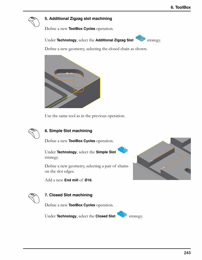
243
6. ToolBox
5. Additional Zigzag slot machining
Define a new ToolBox Cycles operation.
Under Technology, select the Additional Zigzag Slot strategy.
Define a new geometry, selecting the closed chain as shown.
Use the same tool as in the previous operation.
6. Simple Slot machining
Define a new ToolBox Cycles operation.
Under Technology, select the Simple Slot strategy.
Define a new geometry, selecting a pair of chains on the slot edges.
Add a new End mill of Ø16.
7. Closed Slot machining
Define a new ToolBox Cycles operation.
Under Technology, select the Closed Slot strategy.
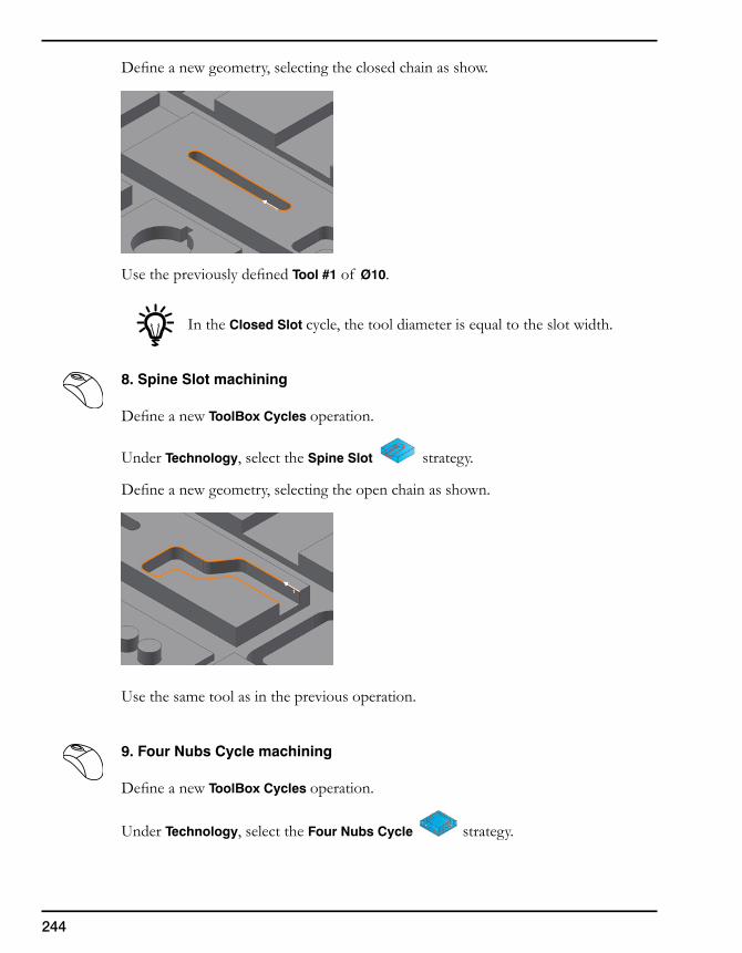
244
Define a new geometry, selecting the closed chain as show.
Use the previously defined Tool #1 of Ø10.
In the Closed Slot cycle, the tool diameter is equal to the slot width.
8. Spine Slot machining
Define a new ToolBox Cycles operation.
Under Technology, select the Spine Slot strategy.
Define a new geometry, selecting the open chain as shown.
Use the same tool as in the previous operation.
9. Four Nubs Cycle machining
Define a new ToolBox Cycles operation.
Under Technology, select the Four Nubs Cycle strategy.
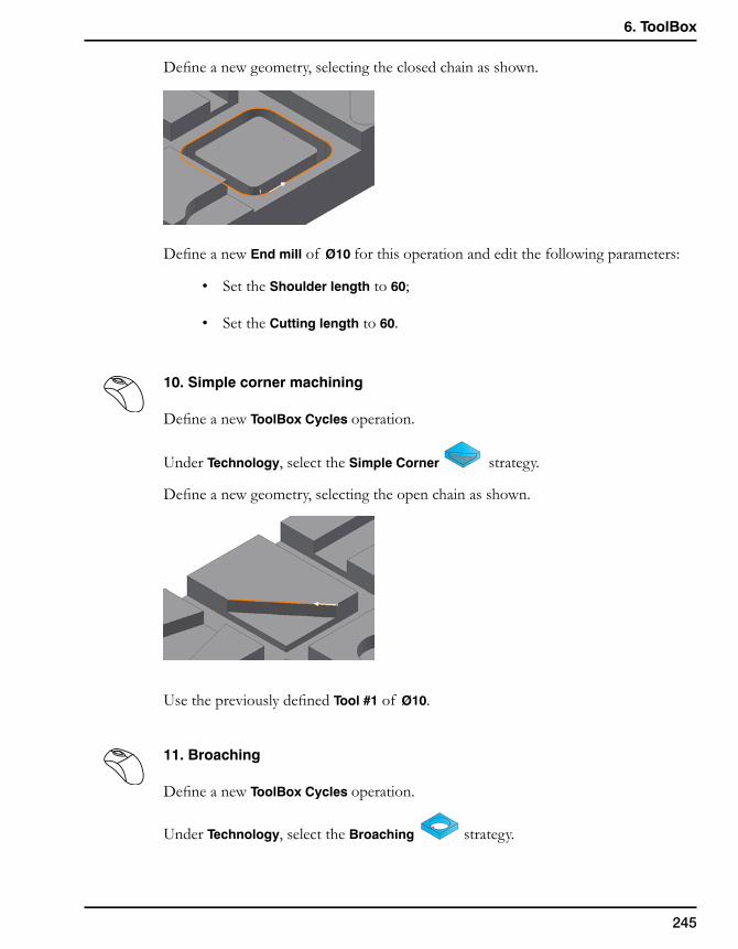
245
6. ToolBox
Define a new geometry, selecting the closed chain as shown.
Define a new End mill of Ø10 for this operation and edit the following parameters:
• Set the Shoulder length to 60;
• Set the Cutting length to 60.
10. Simple corner machining
Define a new ToolBox Cycles operation.
Under Technology, select the Simple Corner strategy.
Define a new geometry, selecting the open chain as shown.
Use the previously defined Tool #1 of Ø10.
11. Broaching
Define a new ToolBox Cycles operation.
Under Technology, select the Broaching strategy.
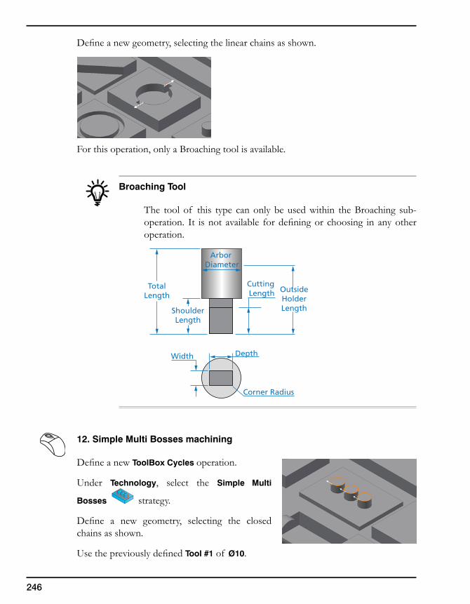
246
Define a new geometry, selecting the linear chains as shown.
For this operation, only a Broaching tool is available.
Broaching Tool
The tool of this type can only be used within the Broaching sub-operation. It is not available for defining or choosing in any other operation.
12. Simple Multi Bosses machining
Define a new ToolBox Cycles operation.
Under Technology, select the Simple Multi
Bosses strategy.
Define a new geometry, selecting the closed chains as shown.
Use the previously defined Tool #1 of Ø10.
Corner Radius
Width Depth
Arbor Diameter
OutsideHolderLength
Cutting Length
ShoulderLength
TotalLength
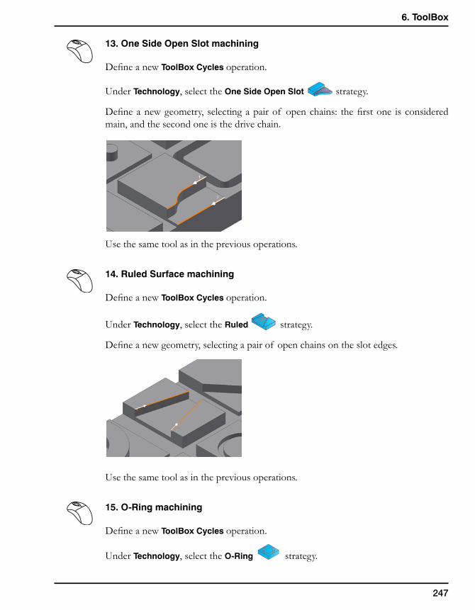
247
6. ToolBox
13. One Side Open Slot machining
Define a new ToolBox Cycles operation.
Under Technology, select the One Side Open Slot strategy.
Define a new geometry, selecting a pair of open chains: the first one is considered main, and the second one is the drive chain.
Use the same tool as in the previous operations.
14. Ruled Surface machining
Define a new ToolBox Cycles operation.
Under Technology, select the Ruled strategy.
Define a new geometry, selecting a pair of open chains on the slot edges.
Use the same tool as in the previous operations.
15. O-Ring machining
Define a new ToolBox Cycles operation.
Under Technology, select the O-Ring strategy.
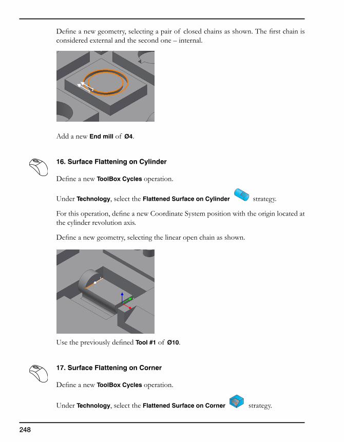
248
Define a new geometry, selecting a pair of closed chains as shown. The first chain is considered external and the second one – internal.
Add a new End mill of Ø4.
16. Surface Flattening on Cylinder
Define a new ToolBox Cycles operation.
Under Technology, select the Flattened Surface on Cylinder strategy.
For this operation, define a new Coordinate System position with the origin located at the cylinder revolution axis.
Define a new geometry, selecting the linear open chain as shown.
Use the previously defined Tool #1 of Ø10.
17. Surface Flattening on Corner
Define a new ToolBox Cycles operation.
Under Technology, select the Flattened Surface on Corner strategy.
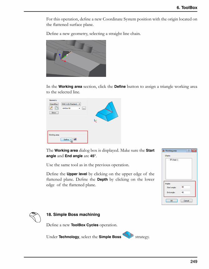
249
6. ToolBox
For this operation, define a new Coordinate System position with the origin located on the flattened surface plane.
Define a new geometry, selecting a straight line chain.
In the Working area section, click the Define button to assign a triangle working area to the selected line.
The Working area dialog box is displayed. Make sure the Start angle and End angle are 45°.
Use the same tool as in the previous operation.
Define the Upper level by clicking on the upper edge of the flattened plane. Define the Depth by clicking on the lower edge of the flattened plane.
18. Simple Boss machining
Define a new ToolBox Cycles operation.
Under Technology, select the Simple Boss strategy.
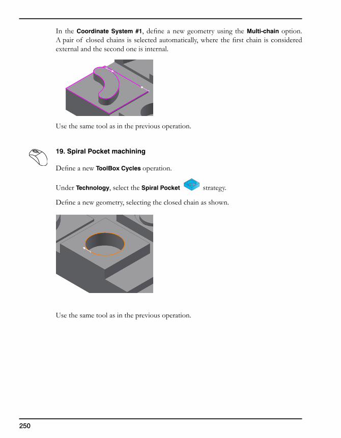
250
In the Coordinate System #1, define a new geometry using the Multi-chain option. A pair of closed chains is selected automatically, where the first chain is considered external and the second one is internal.
Use the same tool as in the previous operation.
19. Spiral Pocket machining
Define a new ToolBox Cycles operation.
Under Technology, select the Spiral Pocket strategy.
Define a new geometry, selecting the closed chain as shown.
Use the same tool as in the previous operation.
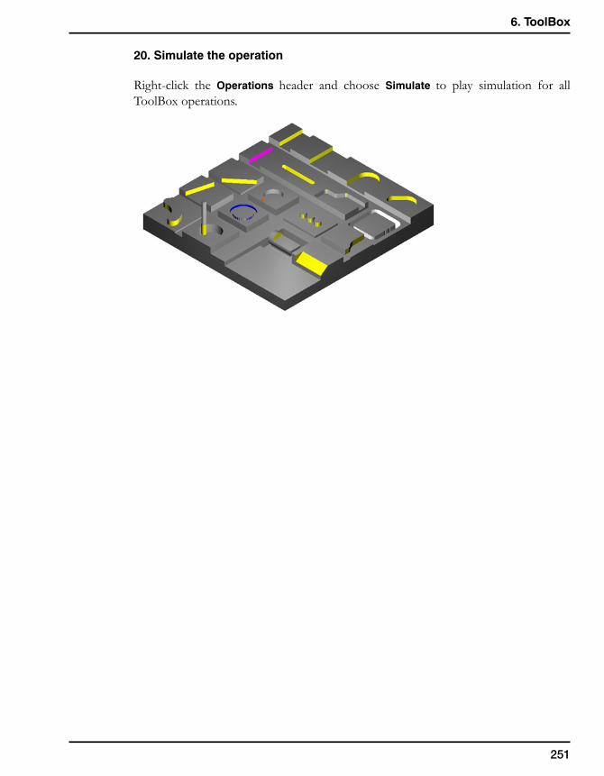
251
6. ToolBox
20. Simulate the operation
Right-click the Operations header and choose Simulate to play simulation for all ToolBox operations.

252

Automatic Feature Recognition 7
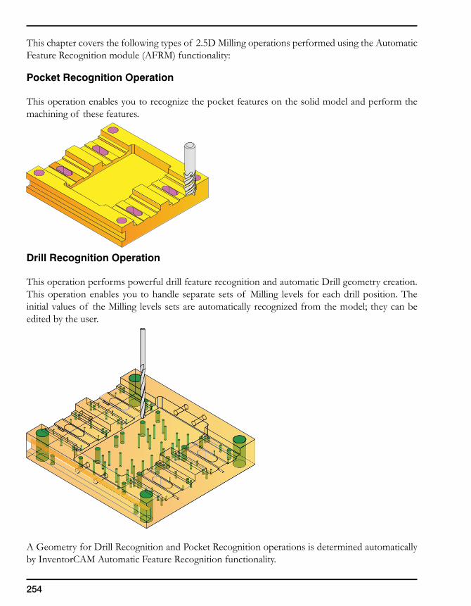
254
This chapter covers the following types of 2.5D Milling operations performed using the Automatic Feature Recognition module (AFRM) functionality:
Pocket Recognition Operation
This operation enables you to recognize the pocket features on the solid model and perform the machining of these features.
Drill Recognition Operation
This operation performs powerful drill feature recognition and automatic Drill geometry creation. This operation enables you to handle separate sets of Milling levels for each drill position. The initial values of the Milling levels sets are automatically recognized from the model; they can be edited by the user.
A Geometry for Drill Recognition and Pocket Recognition operations is determined automatically by InventorCAM Automatic Feature Recognition functionality.
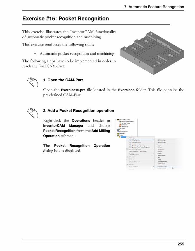
255
7. Automatic Feature Recognition
Exercise #15: Pocket Recognition
This exercise illustrates the InventorCAM functionality of automatic pocket recognition and machining.
This exercise reinforces the following skills:
• Automaticpocketrecognitionandmachining
The following steps have to be implemented in order to reachthefinalCAM-Part:
1. Open the CAM-Part
Open the Exercise15.prz file located in theExercises folder.Thisfile contains thepre-definedCAM-Part.
2. Add a Pocket Recognition operation
Right-click the Operations header in InventorCAM Manager and choose Pocket Recognition from the Add Milling Operation submenu.
The Pocket Recognition Operation dialog box is displayed.
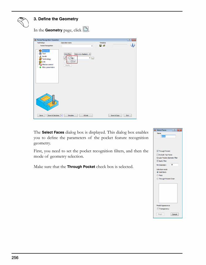
256
3. Define the Geometry
In the Geometry page, click .
The Select Faces dialog box is displayed. This dialog box enables you to define the parameters of the pocket feature recognitiongeometry.
First,youneedtosetthepocketrecognitionfilters,andthenthemode of geometry selection.
Make sure that the Through Pocket check box is selected.
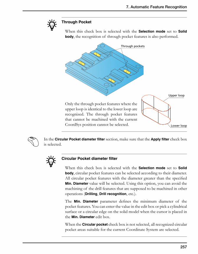
257
7. Automatic Feature Recognition
Through Pocket
When this check box is selected with the Selection mode set to Solid body, the recognition of through pocket features is also performed.
Only the through pocket features where the upper loop is identical to the lower loop are recognized. The through pocket features that cannot be machined with the current CoordSys position cannot be selected.
In the Circular Pocket diameter filter section, make sure that the Apply filter check box is selected.
Circular Pocket diameter filter
When this check box is selected with the Selection mode set to Solid body, circular pocket features can be selected according to their diameter. AllcircularpocketfeatureswiththediametergreaterthanthespecifiedMin. Diameter value will be selected. Using this option, you can avoid the machining of the drill features that are supposed to be machined in other operations (Drilling, Drill recognition, etc.).
The Min. Diameter parameter defines the minimum diameter of thepocket features. You can enter the value in the edit box or pick a cylindrical surface or a circular edge on the solid model when the cursor is placed in the Min. Diameter edit box.
When the Circular pocket check box is not selected, all recognized circular pocket areas suitable for the current Coordinate System are selected.
Through pockets
Upper loop
Lower loop
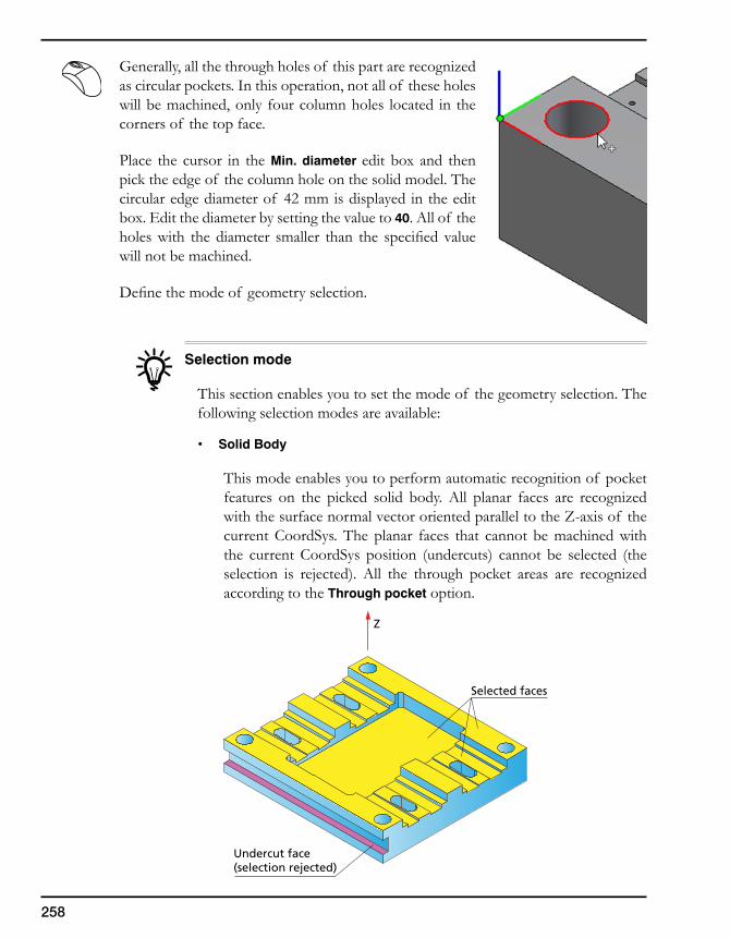
258
Generally, all the through holes of this part are recognized as circular pockets. In this operation, not all of these holes will be machined, only four column holes located in the corners of the top face.
Place the cursor in the Min. diameter edit box and then pick the edge of the column hole on the solid model. The circular edge diameter of 42 mm is displayed in the edit box. Edit the diameter by setting the value to 40. All of the holeswith thediameter smaller than the specifiedvaluewill not be machined.
Definethemodeof geometryselection.
Selection mode
This section enables you to set the mode of the geometry selection. The following selection modes are available:
• SolidBody
This mode enables you to perform automatic recognition of pocket features on the picked solid body. All planar faces are recognized withthesurfacenormalvectororientedparalleltotheZ-axisof thecurrent CoordSys. The planar faces that cannot be machined with the current CoordSys position (undercuts) cannot be selected (the selection is rejected). All the through pocket areas are recognized according to the Through pocket option.
Z
Selected faces
Undercut face(selection rejected)
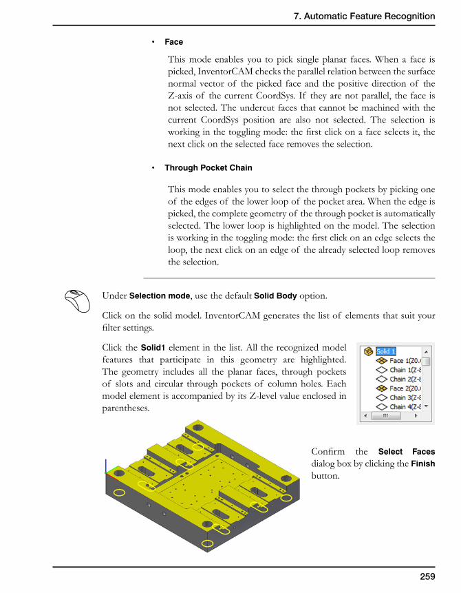
259
7. Automatic Feature Recognition
• Face
This mode enables you to pick single planar faces. When a face is picked, InventorCAM checks the parallel relation between the surface normal vector of the picked face and the positive direction of the Z-axisof thecurrentCoordSys.If theyarenotparallel,thefaceisnot selected. The undercut faces that cannot be machined with the current CoordSys position are also not selected. The selection is workinginthetogglingmode:thefirstclickonafaceselectsit,thenext click on the selected face removes the selection.
• ThroughPocketChain
This mode enables you to select the through pockets by picking one of the edges of the lower loop of the pocket area. When the edge is picked, the complete geometry of the through pocket is automatically selected. The lower loop is highlighted on the model. The selection isworkinginthetogglingmode:thefirstclickonanedgeselectstheloop, the next click on an edge of the already selected loop removes the selection.
Under Selection mode, use the defaultSolidBody option.
Click on the solid model. InventorCAM generates the list of elements that suit your filtersettings.
Click the Solid1 element in the list. All the recognized model features that participate in this geometry are highlighted. The geometry includes all the planar faces, through pockets of slots and circular through pockets of column holes. Each modelelementisaccompaniedbyitsZ-levelvalueenclosedinparentheses.
Confirm the Select Faces dialog box by clicking the Finish button.
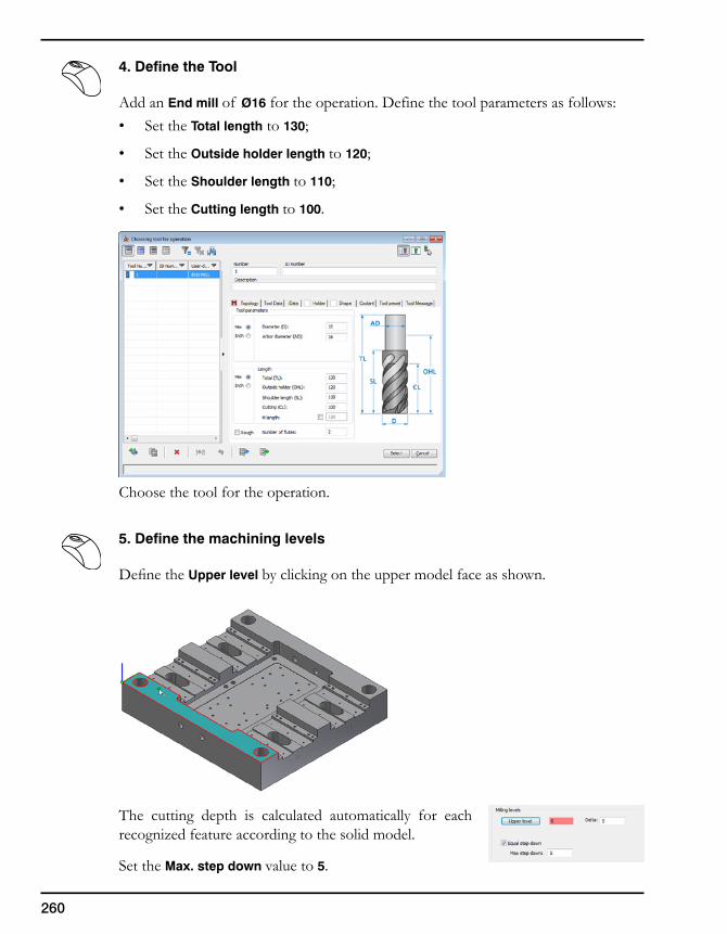
260
4. Define the Tool
Add an End mill of Ø16 for the operation. Define the tool parameters as follows:• SettheTotal length to 130;
• SettheOutside holder length to 120;
• SettheShoulder length to 110;
• SettheCutting length to 100.
Choose the tool for the operation.
5. Define the machining levels
DefinetheUpper level by clicking on the upper model face as shown.
The cutting depth is calculated automatically for each recognized feature according to the solid model.
Set the Max. step down value to 5.
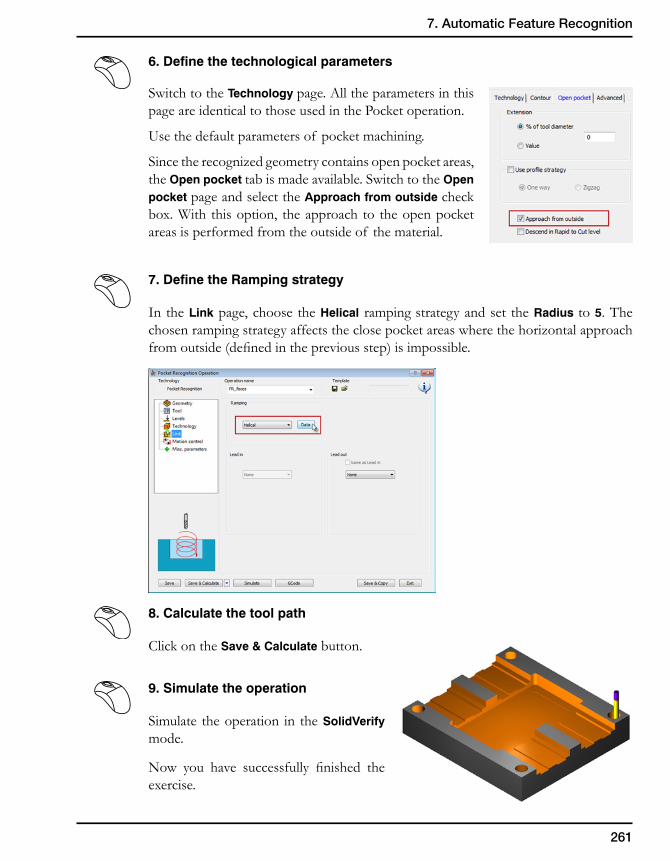
261
7. Automatic Feature Recognition
6. Define the technological parameters
Switch to the Technology page. All the parameters in this page are identical to those used in the Pocket operation.
Use the default parameters of pocket machining.
Since the recognized geometry contains open pocket areas, the Open pocket tab is made available. Switch to the Open pocket page and select the Approach from outside check box. With this option, the approach to the open pocket areas is performed from the outside of the material.
7. Define the Ramping strategy
In the Link page, choose the Helical ramping strategy and set the Radius to 5. The chosen ramping strategy affects the close pocket areas where the horizontal approach fromoutside(definedinthepreviousstep)isimpossible.
8. Calculate the tool path
Click on the Save & Calculate button.
9. Simulate the operation
Simulate the operation in the SolidVerify mode.
Now you have successfully finished theexercise.
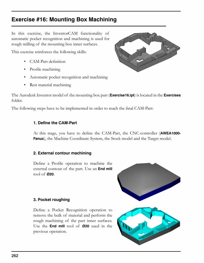
262
Exercise#16:MountingBoxMachining
In this exercise, the InventorCAM functionality of automatic pocket recognition and machining is used for rough milling of the mounting box inner surfaces.
This exercise reinforces the following skills:
• CAM-Partdefinition
• Profilemachining
• Automaticpocketrecognitionandmachining
• Restmaterialmachining
The Autodesk Inventor model of the mounting box part (Exercise16.ipt) is located in the Exercises folder.
ThefollowingstepshavetobeimplementedinordertoreachthefinalCAM-Part:
1. Define the CAM-Part
At this stage, you have to define the CAM-Part, the CNC-controller (AWEA1000-Fanuc), the Machine Coordinate System, the Stock model and the Target model.
2. External contour machining
Define a Profile operation to machine theexternal contour of the part. Use an End mill tool of Ø20.
3. Pocket roughing
Define a Pocket Recognition operation toremove the bulk of material and perform the rough machining of the part inner surfaces. Use the End mill tool of Ø20 used in the previous operation.
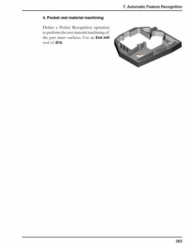
263
7. Automatic Feature Recognition
4. Pocket rest material machining
Define a Pocket Recognition operationto perform the rest material machining of the part inner surfaces. Use an End mill tool of Ø10.
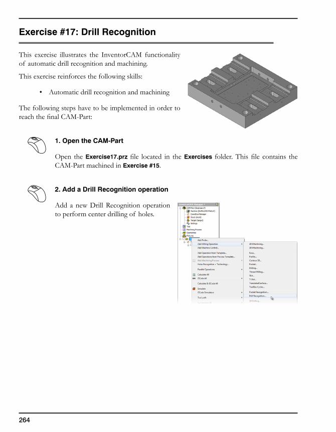
264
Exercise #17: Drill Recognition
This exercise illustrates the InventorCAM functionality of automatic drill recognition and machining.
This exercise reinforces the following skills:
• Automaticdrillrecognitionandmachining
The following steps have to be implemented in order to reachthefinalCAM-Part:
1. Open the CAM-Part
Open the Exercise17.prz file located in theExercises folder.Thisfile contains theCAM-PartmachinedinExercise #15.
2. Add a Drill Recognition operation
Add a new Drill Recognition operation to perform center drilling of holes.
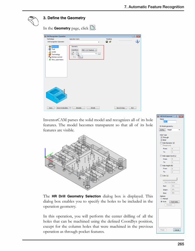
265
7. Automatic Feature Recognition
3. Define the Geometry
In the Geometry page, click .
InventorCAM parses the solid model and recognizes all of its hole features. The model becomes transparent so that all of its hole features are visible.
The HR Drill Geometry Selection dialog box is displayed. This dialog box enables you to specify the holes to be included in the operation geometry.
In this operation, you will perform the center drilling of all the holesthatcanbemachinedusingthedefinedCoordSysposition,except for the column holes that were machined in the previous operation as through pocket features.
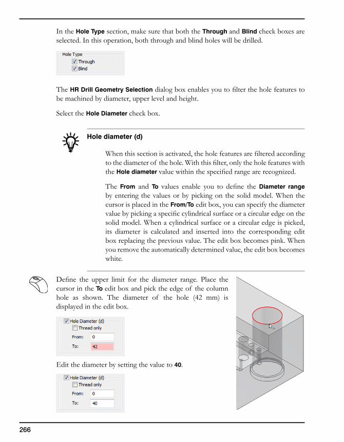
266
In the Hole Type section, make sure that both the Through and Blindcheck boxes are selected. In this operation, both through and blind holes will be drilled.
The HR Drill Geometry Selectiondialogboxenablesyoutofiltertheholefeaturestobe machined by diameter, upper level and height.
Select the Hole Diameter check box.
Hole diameter (d)
Whenthissectionisactivated,theholefeaturesarefilteredaccordingtothediameterof thehole.Withthisfilter,onlytheholefeatureswiththe Hole diameter valuewithinthespecifiedrangearerecognized.
The From and To values enable you to define theDiameter range by entering the values or by picking on the solid model. When the cursor is placed in the From/To edit box, you can specify the diameter valuebypickingaspecificcylindricalsurfaceoracircularedgeonthesolid model. When a cylindrical surface or a circular edge is picked, its diameter is calculated and inserted into the corresponding edit box replacing the previous value. The edit box becomes pink. When you remove the automatically determined value, the edit box becomes white.
Define the upper limit for the diameter range. Place thecursor in the To edit box and pick the edge of the column hole as shown. The diameter of the hole (42 mm) is displayed in the edit box.
Edit the diameter by setting the value to 40.
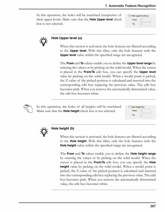
267
7. Automatic Feature Recognition
In this operation, the holes will be machined irrespective of their upper levels. Make sure that the Hole Upper level check box is not selected.
Hole Upper level (u)
Whenthissectionisactivated,theholefeaturesarefilteredaccordingto the Upper level.With thisfilter,only thehole featureswith theUpper level valuewithinthespecifiedrangearerecognized.
The From and To valuesenableyoutodefinetheUpper level range by entering the values or by picking on the solid model. When the cursor is placed in the From/To edit box, you can specify the Upper level value by picking on the solid model. When a model point is picked, theZ-valueof thepickedpositioniscalculatedandinsertedintothecorresponding edit box replacing the previous value. The edit box becomes pink. When you remove the automatically determined value, the edit box becomes white.
In this operation, the holes of all heights will be machined. Make sure that the Hole height check box is not selected.
Hole height (h)
Whenthissectionisactivated,theholefeaturesarefilteredaccordingto the Hole height.With thisfilter,only thehole featureswith theHole heightvaluewithinthespecifiedrangearerecognized.
The From and To valuesenableyoutodefinetheHole height range by entering the values or by picking on the solid model. When the cursor is placed in the From/To edit box, you can specify the Hole height value by picking on the solid model. When a model point is picked,theZ-valueof thepickedpositioniscalculatedandinsertedinto the corresponding edit box replacing the previous value. The edit box becomes pink. When you remove the automatically determined value, the edit box becomes white.
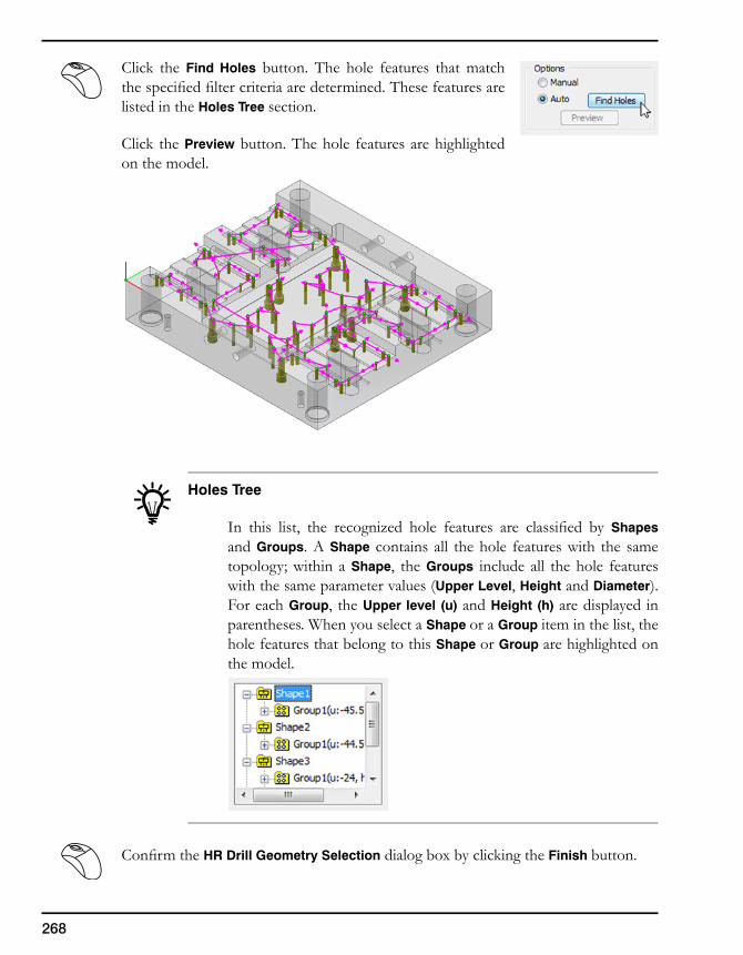
268
Click the Find Holes button. The hole features that match thespecifiedfiltercriteriaaredetermined.Thesefeaturesarelisted in the Holes Tree section.
Click the Preview button. The hole features are highlighted on the model.
Holes Tree
In this list, the recognized hole features are classified by Shapes and Groups. A Shape contains all the hole features with the same topology; within a Shape, the Groups include all the hole features with the same parameter values (Upper Level, Height and Diameter). For each Group, the Upper level (u) and Height (h) are displayed in parentheses. When you select a Shape or a Group item in the list, the hole features that belong to this Shape or Group are highlighted on the model.
ConfirmtheHR Drill Geometry Selection dialog box by clicking the Finish button.
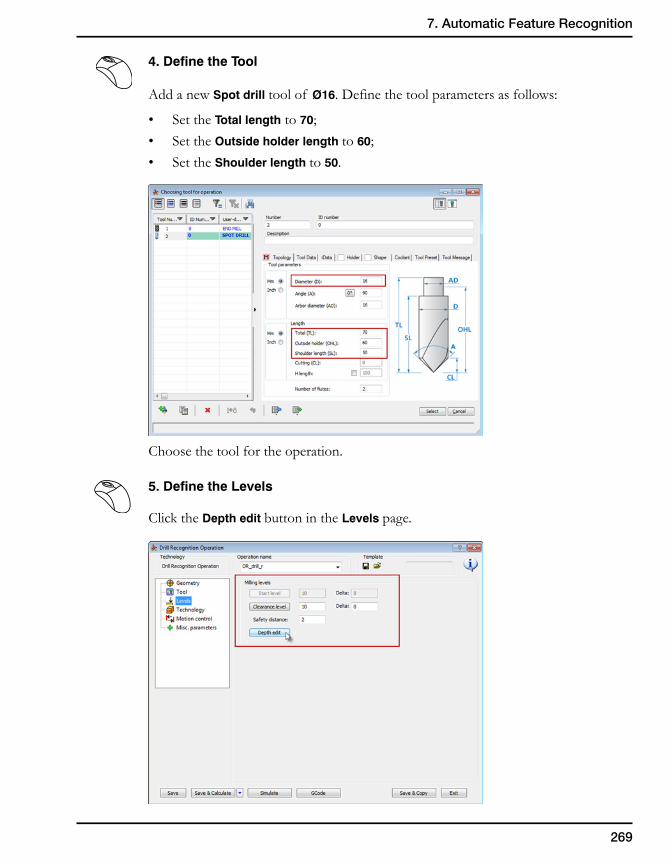
269
7. Automatic Feature Recognition
4. Define the Tool
Add a new Spot drill tool of Ø16. Define the tool parameters as follows:
• SettheTotal length to 70;• SettheOutside holder length to 60;• SettheShoulder length to 50.
Choose the tool for the operation.
5. Define the Levels
Click the Depth edit button in the Levels page.
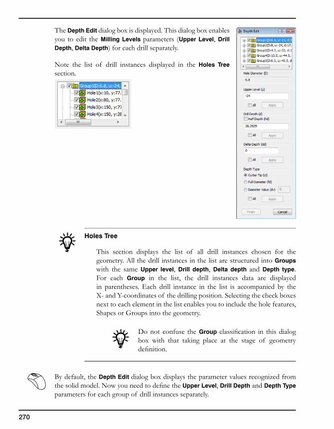
270
The Depth Edit dialog box is displayed. This dialog box enables you to edit the Milling Levels parameters (Upper Level, Drill Depth, Delta Depth) for each drill separately.
Note the list of drill instances displayed in the Holes Tree section.
Holes Tree
This section displays the list of all drill instances chosen for the geometry. All the drill instances in the list are structured into Groups with the same Upper level, Drill depth, Delta depth and Depth type. For each Group in the list, the drill instances data are displayed in parentheses. Each drill instance in the list is accompanied by the X-andY-coordinatesof thedrillingposition.Selectingthecheckboxesnext to each element in the list enables you to include the hole features, Shapes or Groups into the geometry.
Do not confuse the Group classification in this dialogbox with that taking place at the stage of geometry definition.
By default, the Depth Edit dialog box displays the parameter values recognized from thesolidmodel.NowyouneedtodefinetheUpper Level, Drill Depth and Depth Type parameters for each group of drill instances separately.
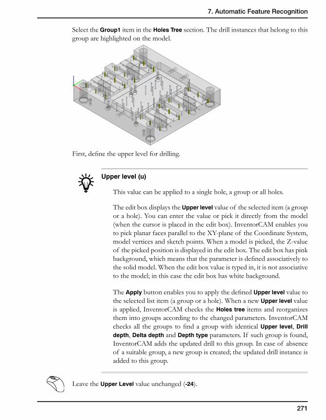
271
7. Automatic Feature Recognition
Select the Group1 item in the Holes Tree section. The drill instances that belong to this group are highlighted on the model.
First,definetheupperlevelfordrilling.
Upper level (u)
This value can be applied to a single hole, a group or all holes.
The edit box displays the Upper level value of the selected item (a group or a hole). You can enter the value or pick it directly from the model (when the cursor is placed in the edit box). InventorCAM enables you topickplanarfacesparalleltotheXY-planeof theCoordinateSystem,modelverticesandsketchpoints.Whenamodelispicked,theZ-valueof the picked position is displayed in the edit box. The edit box has pink background,whichmeansthattheparameterisdefinedassociativelytothe solid model. When the edit box value is typed in, it is not associative to the model; in this case the edit box has white background.
The ApplybuttonenablesyoutoapplythedefinedUpper level value to the selected list item (a group or a hole). When a new Upper level value is applied, InventorCAM checks the Holes tree items and reorganizes them into groups according to the changed parameters. InventorCAM checksall thegroupstofindagroupwith identicalUpper level, Drill depth, Delta depth and Depth type parameters. If such group is found, InventorCAM adds the updated drill to this group. In case of absence of a suitable group, a new group is created; the updated drill instance is added to this group.
Leave the Upper Level value unchanged (-24).
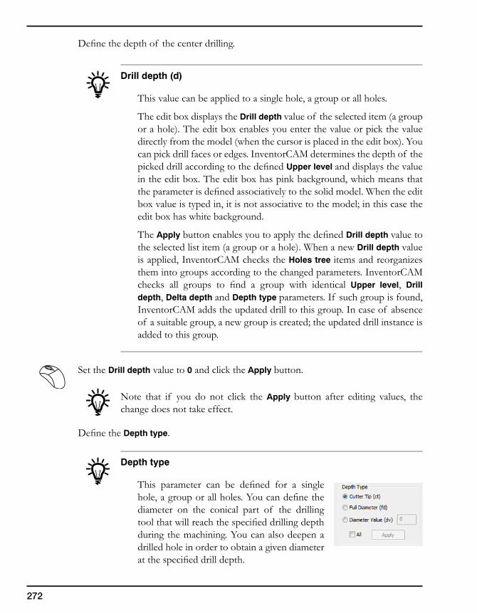
272
Definethedepthof thecenterdrilling.
Drill depth (d)
This value can be applied to a single hole, a group or all holes.
The edit box displays the Drill depth value of the selected item (a group or a hole). The edit box enables you enter the value or pick the value directly from the model (when the cursor is placed in the edit box). You can pick drill faces or edges. InventorCAM determines the depth of the pickeddrillaccordingtothedefinedUpper level and displays the value in the edit box. The edit box has pink background, which means that theparameterisdefinedassociativelytothesolidmodel.Whentheeditbox value is typed in, it is not associative to the model; in this case the edit box has white background.
The Apply buttonenablesyoutoapplythedefinedDrill depth value to the selected list item (a group or a hole). When a new Drill depth value is applied, InventorCAM checks the Holes tree items and reorganizes them into groups according to the changed parameters. InventorCAM checks all groups to find a group with identical Upper level, Drill depth, Delta depth and Depth type parameters. If such group is found, InventorCAM adds the updated drill to this group. In case of absence of a suitable group, a new group is created; the updated drill instance is added to this group.
Set the Drill depth value to 0 and click the Apply button.
Note that if you do not click the Apply button after editing values, the change does not take effect.
DefinetheDepth type.
Depth type
This parameter can be defined for a singlehole,agrouporallholes.Youcandefinethediameter on the conical part of the drilling toolthatwillreachthespecifieddrillingdepthduring the machining. You can also deepen a drilled hole in order to obtain a given diameter atthespecifieddrilldepth.
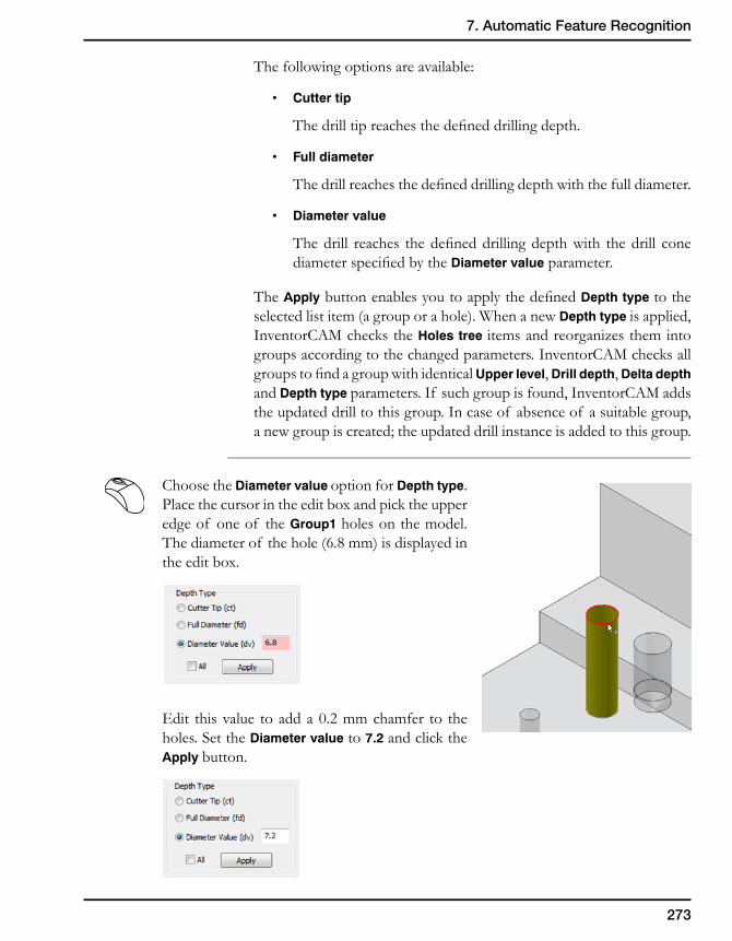
273
7. Automatic Feature Recognition
The following options are available:
• Cuttertip
Thedrilltipreachesthedefineddrillingdepth.
• Fulldiameter
Thedrillreachesthedefineddrillingdepthwiththefulldiameter.
• Diametervalue
Thedrill reaches thedefineddrillingdepthwith thedrill conediameterspecifiedbytheDiameter value parameter.
The ApplybuttonenablesyoutoapplythedefinedDepth type to the selected list item (a group or a hole). When a new Depth type is applied, InventorCAM checks the Holes tree items and reorganizes them into groups according to the changed parameters. InventorCAM checks all groupstofindagroupwithidenticalUpper level, Drill depth, Delta depth and Depth type parameters. If such group is found, InventorCAM adds the updated drill to this group. In case of absence of a suitable group, a new group is created; the updated drill instance is added to this group.
Choose the Diameter value option for Depth type. Place the cursor in the edit box and pick the upper edge of one of the Group1 holes on the model. The diameter of the hole (6.8 mm) is displayed in the edit box.
Edit this value to add a 0.2 mm chamfer to the holes. Set the Diameter value to 7.2 and click the Apply button.
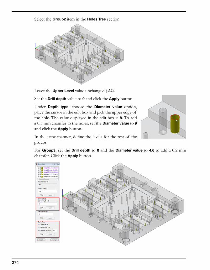
274
Select the Group2 item in the Holes Tree section.
Leave the Upper Level value unchanged (-24).
Set the Drill depth value to 0 and click the Apply button.
Under Depth type, choose the Diameter value option, place the cursor in the edit box and pick the upper edge of the hole. The value displayed in the edit box is 8. To add a 0.5 mm chamfer to the holes, set the Diameter value to 9 and click the Apply button.
Inthesamemanner,definethelevelsfortherestof thegroups.
For Group3, set the Drill depth to 0 and the Diameter value to 4.6 to add a 0.2 mm chamfer. Click the Apply button.
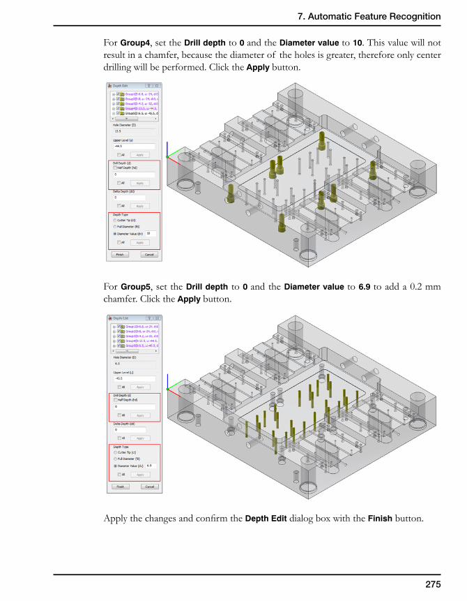
275
7. Automatic Feature Recognition
For Group4, set the Drill depth to 0 and the Diameter value to 10. This value will not result in a chamfer, because the diameter of the holes is greater, therefore only center drilling will be performed. Click the Apply button.
For Group5, set the Drill depth to 0 and the Diameter value to 6.9 to add a 0.2 mm chamfer. Click the Apply button.
ApplythechangesandconfirmtheDepth Edit dialog box with the Finish button.
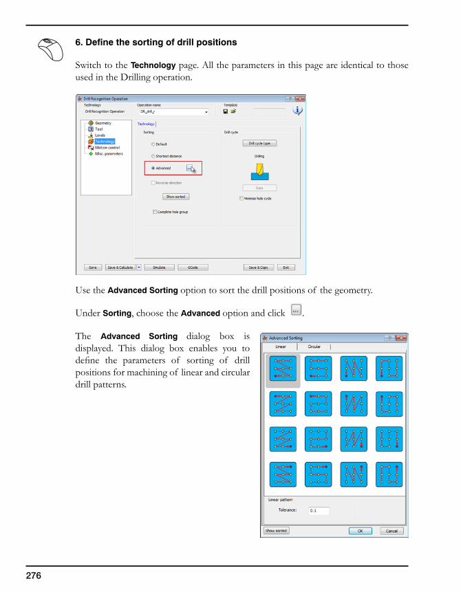
276
6. Define the sorting of drill positions
Switch to the Technology page. All the parameters in this page are identical to those used in the Drilling operation.
Use the Advanced Sorting option to sort the drill positions of the geometry.
Under Sorting, choose the Advanced option and click .
The Advanced Sorting dialog box is displayed. This dialog box enables you to define the parameters of sorting of drillpositions for machining of linear and circular drill patterns.
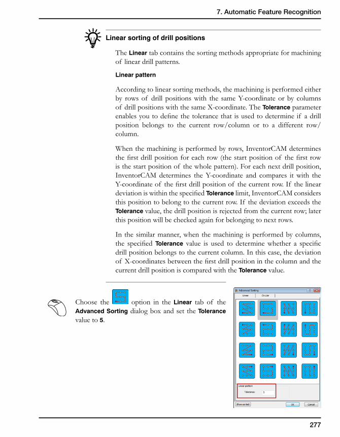
277
7. Automatic Feature Recognition
Linear sorting of drill positions
The Linear tab contains the sorting methods appropriate for machining of linear drill patterns.
Linear pattern
According to linear sorting methods, the machining is performed either by rowsof drillpositionswith the sameY-coordinateorbycolumnsof drillpositionswiththesameX-coordinate.TheTolerance parameter enablesyoutodefinethetolerancethat isusedtodetermineif adrillposition belongs to the current row/column or to a different row/column.
When the machining is performed by rows, InventorCAM determines thefirstdrillpositionforeachrow(thestartpositionof thefirstrowis the start position of the whole pattern). For each next drill position, InventorCAMdetermines theY-coordinate and compares itwith theY-coordinateof thefirstdrillpositionof thecurrentrow.If thelineardeviationiswithinthespecifiedTolerance limit, InventorCAM considers this position to belong to the current row. If the deviation exceeds the Tolerance value, the drill position is rejected from the current row; later this position will be checked again for belonging to next rows.
In the similar manner, when the machining is performed by columns, the specifiedTolerance value is used to determinewhether a specificdrill position belongs to the current column. In this case, the deviation of X-coordinatesbetweenthefirstdrillpositioninthecolumnandthecurrent drill position is compared with the Tolerance value.
Choose the option in the Linear tab of the Advanced Sorting dialog box and set the Tolerance value to 5.
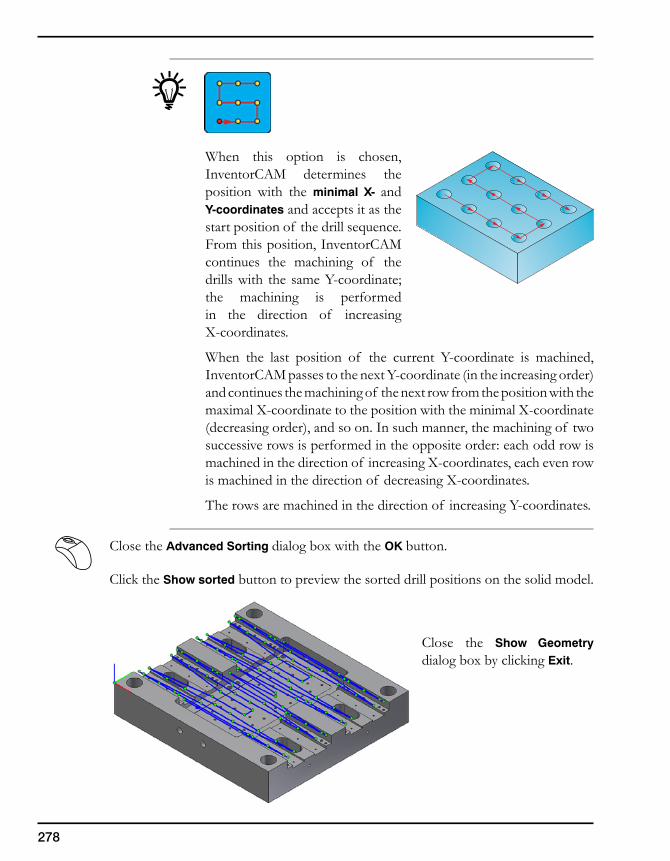
278
When this option is chosen, InventorCAM determines the position with the minimal X- and Y-coordinates and accepts it as the start position of the drill sequence. From this position, InventorCAM continues the machining of the drillswith the sameY-coordinate;the machining is performed in the direction of increasing X-coordinates.
When the last position of the current Y-coordinate is machined,InventorCAMpassestothenextY-coordinate(intheincreasingorder)and continues the machining of the next row from the position with the maximalX-coordinatetothepositionwiththeminimalX-coordinate(decreasing order), and so on. In such manner, the machining of two successive rows is performed in the opposite order: each odd row is machinedinthedirectionof increasingX-coordinates,eachevenrowismachinedinthedirectionof decreasingX-coordinates.
Therowsaremachinedinthedirectionof increasingY-coordinates.
Close the Advanced Sorting dialog box with the OK button.
Click the Show sorted button to preview the sorted drill positions on the solid model.
Close the Show Geometry dialog box by clicking Exit.
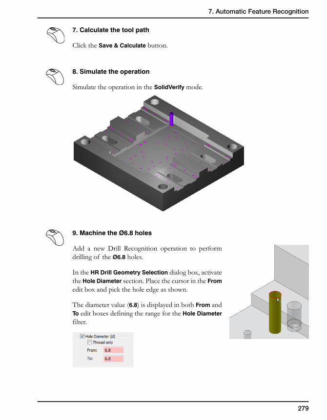
279
7. Automatic Feature Recognition
7. Calculate the tool path
Click the Save & Calculate button.
8. Simulate the operation
Simulate the operation in the SolidVerify mode.
9. Machine the Ø6.8 holes
Add a new Drill Recognition operation to perform drilling of the Ø6.8 holes.
In the HR Drill Geometry Selection dialog box, activate the Hole Diameter section. Place the cursor in the From edit box and pick the hole edge as shown.
The diameter value (6.8) is displayed in both From and To edit boxes defining the range for the Hole Diameter filter.
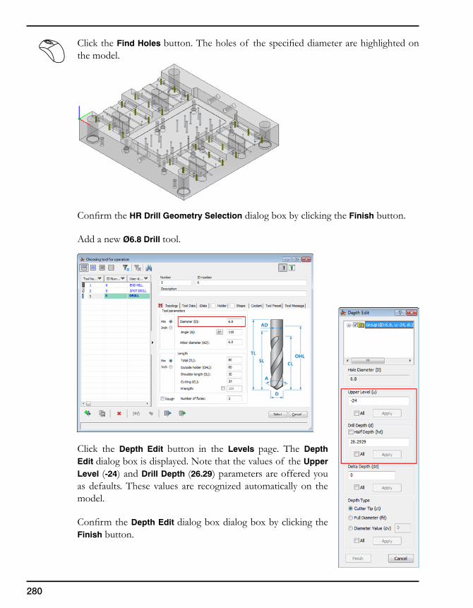
280
Click the Find Holes button.Theholesof thespecifieddiameterarehighlightedonthe model.
ConfirmtheHR Drill Geometry Selection dialog box by clicking the Finish button.
Add a new Ø6.8 Drill tool.
Click the Depth Edit button in the Levels page. The Depth Edit dialog box is displayed. Note that the values of the Upper Level (-24) and Drill Depth (26.29) parameters are offered you as defaults. These values are recognized automatically on the model.
ConfirmtheDepth Edit dialog box dialog box by clicking the Finish button.
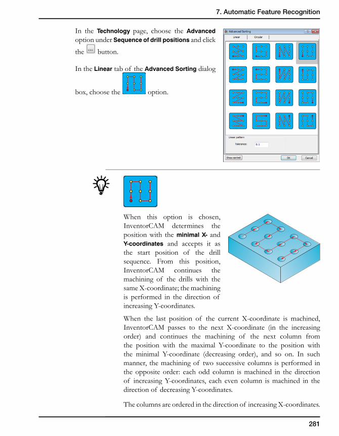
281
7. Automatic Feature Recognition
In the Technology page, choose the Advanced option under Sequence of drill positions and click
the button.
In the Linear tab of the Advanced Sorting dialog
box, choose the option.
When this option is chosen, InventorCAM determines the position with the minimal X- and Y-coordinates and accepts it as the start position of the drill sequence. From this position, InventorCAM continues the machining of the drills with the sameX-coordinate;themachiningis performed in the direction of increasingY-coordinates.
When the last position of the current X-coordinate is machined,InventorCAM passes to the next X-coordinate (in the increasingorder) and continues the machining of the next column from the position with the maximal Y-coordinate to the position withthe minimal Y-coordinate (decreasing order), and so on. In suchmanner, the machining of two successive columns is performed in the opposite order: each odd column is machined in the direction of increasingY-coordinates, each even column ismachined in thedirectionof decreasingY-coordinates.
Thecolumnsareorderedinthedirectionof increasingX-coordinates.
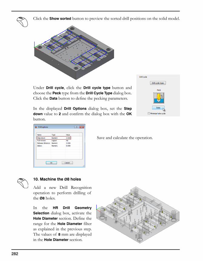
282
Click the Show sorted button to preview the sorted drill positions on the solid model.
Under Drill cycle, click the Drill cycle type button and choose the Peck type from the Drill Cycle Type dialog box. Click the Data buttontodefinethepeckingparameters.
In the displayed Drill Options dialog box, set the Step down value to 2 andconfirmthedialogboxwiththeOK button.
Save and calculate the operation.
10. Machine the Ø8 holes
Add a new Drill Recognition operation to perform drilling of the Ø8 holes.
In the HR Drill Geometry Selection dialog box, activate the Hole Diameter section. Define the range for the Hole Diameter filter as explained in the previous step. The values of 8 mm are displayed in the Hole Diameter section.
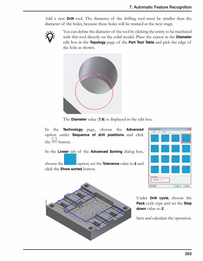
283
7. Automatic Feature Recognition
Add a new Drill tool. The diameter of the drilling tool must be smaller than the diameter of the holes, because these holes will be reamed at the next stage.
Youcandefinethediameterof thetoolbyclickingtheentitytobemachinedwith this tool directly on the solid model. Place the cursor in the Diameter edit box in the Topology page of the Part Tool Table and pick the edge of the hole as shown.
The Diameter value (7.8) is displayed in the edit box.
In the Technology page, choose the Advanced option under Sequence of drill positions and click
the button.
In the Linear tab of the Advanced Sorting dialog box,
choose the option, set the Tolerance value to 2 and click the Show sorted button.
Under Drill cycle, choose the Peck cycle type and set the Step down value to 2.
Save and calculate the operation.
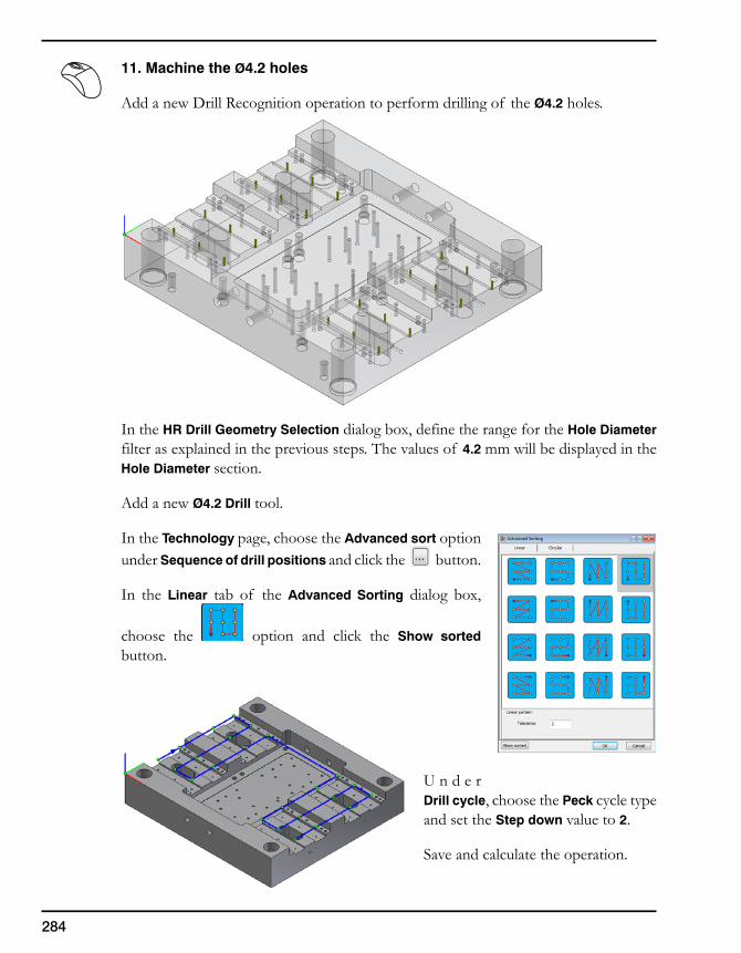
284
11. Machine the Ø4.2 holes
Add a new Drill Recognition operation to perform drilling of the Ø4.2 holes.
In the HR Drill Geometry Selection dialog box, define the range for the Hole Diameter filter as explained in the previous steps. The values of 4.2 mm will be displayed in the Hole Diameter section.
Add a new Ø4.2 Drill tool.
In the Technology page, choose the Advanced sort option under Sequence of drill positions and click the button.
In the Linear tab of the Advanced Sorting dialog box,
choose the option and click the Show sorted button.
U n d e r Drill cycle, choose the Peck cycle type and set the Step down value to 2.
Save and calculate the operation.
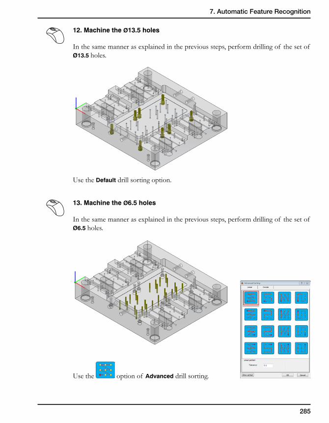
285
7. Automatic Feature Recognition
12. Machine the Ø13.5 holes
In the same manner as explained in the previous steps, perform drilling of the set of Ø13.5 holes.
Use the Default drill sorting option.
13. Machine the Ø6.5 holes
In the same manner as explained in the previous steps, perform drilling of the set of Ø6.5 holes.
Use the option of Advanced drill sorting.
286
When this option is chosen, Inventor determines the position with the minimal X- and Y-coordinates and accepts it as the start position of the drill sequence. From this position, InventorCAM continues the machining of the drills with the sameY-coordinate;themachiningis performed in the direction of increasingX-coordinates.
When the last position of the current Y-coordinate is machined,InventorCAM passes to the next Y-coordinate (in the increasingorder) and continues the machining of the next row from the position with the minimal X-coordinate to the position with themaximalX-coordinate(increasingorder)andsoon.Insuchmanner,the machining of the rows is performed in the same direction of increasingX-coordinates.
The ordering of rows is performed in the direction of increasing Y-coordinates.
Click the Show sorted button to preview the sorted drill positions on the solid model.
287
7. Automatic Feature Recognition
14. Perform reaming of the Ø8 holes
Add a new Drill Recognition operation to perform reaming of the Ø8 holes.
Use the drill_r2geometrydefinedinStep #10.
Add a new Ø8 Reamer tool.
Reamer
This tool is used to machine precise holes in Drilling operations. Atoolof thistypeisdefinedwiththeparametersshownintheimage.
OutsideHolderLength
CuttingLength
ChamferLengthDiameter
TotalLength
ArborDiameter
288
Todefinethedepth,pickthemodelfaceasshown.
The Drill depth value (12) is displayed. Click the Apply button.
Definethesortingof drillpositionsasexplainedinStep #10.
Click the Save & Calculate button.
15. Simulate the operations
SimulatetheoperationsdefinedinStep #9 – Step #14 in the SolidVerify mode.
Nowyouhavesuccessfullyfinishedtheexercise.
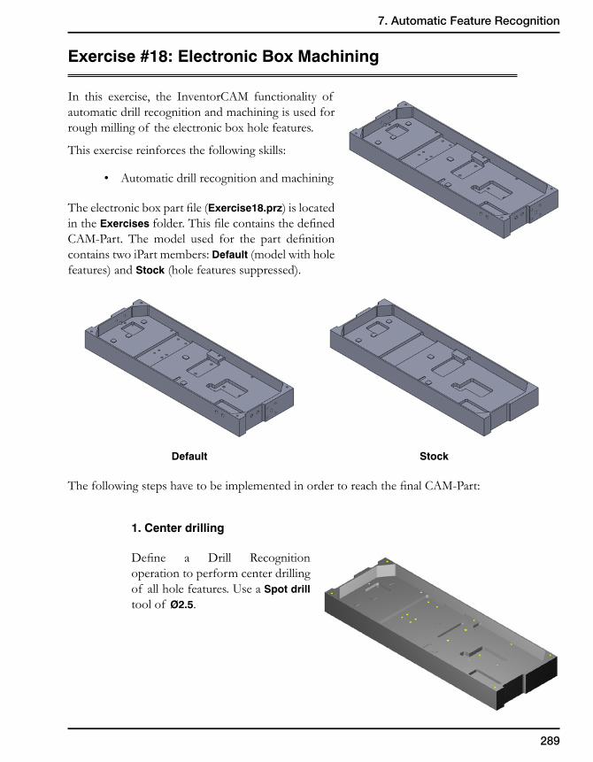
289
7. Automatic Feature Recognition
Exercise#18:ElectronicBoxMachining
In this exercise, the InventorCAM functionality of automatic drill recognition and machining is used for rough milling of the electronic box hole features.
This exercise reinforces the following skills:
• Automaticdrillrecognitionandmachining
Theelectronicboxpartfile(Exercise18.prz) is located in the Exercises folder.ThisfilecontainsthedefinedCAM-Part. Themodel used for the part definitioncontains two iPart members: Default (model with hole features) and Stock (hole features suppressed).
Default Stock
ThefollowingstepshavetobeimplementedinordertoreachthefinalCAM-Part:
1. Center drilling
Define a Drill Recognitionoperation to perform center drilling of all hole features. Use a Spot drill tool of Ø2.5.
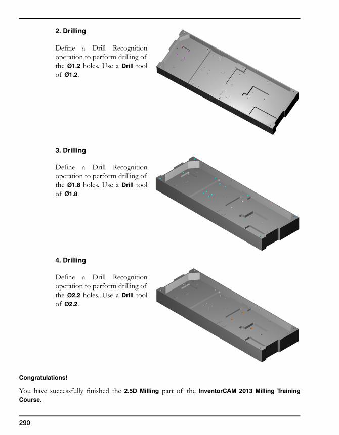
290
2. Drilling
Define a Drill Recognitionoperation to perform drilling of the Ø1.2 holes. Use a Drill tool of Ø1.2.
3. Drilling
Define a Drill Recognitionoperation to perform drilling of the Ø1.8 holes. Use a Drill tool of Ø1.8.
4. Drilling
Define a Drill Recognitionoperation to perform drilling of the Ø2.2 holes. Use a Drill tool of Ø2.2.
Congratulations!
You have successfully finished the 2.5D Milling part of the InventorCAM 2013 Milling Training Course.

291
7. Automatic Feature Recognition
2012 SolidCAM Ltd. All rights reserved. All brands and product names are registered trademarks of their respective owners.
www.inventorcam.com
www.youtube.com/SolidCAMProfessor www.youtube.com/iMachining
www.facebook.com/SolidCAMwww.facebook.com/iMachining
2.5D Milling HSS (High-Speed Surface Machining) HSM (High-Speed Machining)
Wire EDM iMachining Service and Support
Indexed Multi-Sided Machining Simultaneous 5-Axis Machining Turning and Mill-Turn up to 5-Axis
The complete integrated Manufacturing Solution
InventorCAM + InventorAutodesk® Inventor®
2013 Certi�ed


](https://static.fdocuments.in/doc/165x107/5562ac71d8b42a7c4a8b51ad/presentation15-b15d5b15d1carolina-panthersgalea.jpg)