
Invar Wire Calibration and Measurement at the … · V/253 INVAR WIRE CALIBRATION AND MEASUREMENT...
14
V/253 INVAR WIRE CALIBRATION AND MEASUREMENT AT THE SYNCHROTRON RADIATION RESEARCH CENTER Spencer Chen Synchrotron Radiation Research Center Hsinchu, Taiwan, R.O.C. 30007 ABSTRACT The length measurement technique for the storage ring at the Sychroton Radiation Research Center (SRRC) is based on invar wire. To keep the alignment tolerance in the ±0.10 mm range for the magnets along the 120m circumference, the calibration and length measurement accuracy for the invar wire should be in the range of ± 0.03 mm. Major contributed errors in both calibration and length measurement are identified. To minimize the errors we have implemented certain improvements in the area of instruments, fixtures and baseline. After we reduce systematic errors through the hardware approach, the computation chart is introduced to compensate to the systematic errors. From network analysis, the result is very consistent in both length and angular measurements. 1. INTRODUCTION The circumference of most of the dedicated storage rings for synchrotron radiation is in the 20 to 800 meters range. To position the magnetic components, which keep the electrons in their orbit, is the task of the survey and alignment group. This wire technique for the installation of the accelerator components represents the “gaps” between metrological measurements in the laboratory and normal geodetic practice. This intermediate range of measurement from 10 to 1,000 m, could be called macro-metrology or micro-geodesy[1]. New distance measurement systems have been developed, such as the Electronic Distance Measurement EDM[2] and the 3-D Laser Tracking System[3,4]. The invar wire measurement[5] still plays its role in the small accelerators because of economy and ease of operation. The length measurement at the SRRC is based on the invar wire technique, Fig.1. 2. OPERATION AND CALIBRATION During field measurements we use reference sockets, 30 mm diameter, to define the control points of magnets and survey locations. The invar wire is held by the tension puller distinvar[6] and fixed poster, both are inserted into the reference sockets. The distance between reference sockets is equivalent to the wire length and read-out of the distinvar. The nomial wire length can not be obtained from mechanical devices because the wire is too long to measure. It must be calibrated with a laser interferometer technique. The invar wire is rather soft and easy to bend during pulling operation and rolling/unrolling procedures. Therefore the nomial length after wire buckling changes from the 0.1 to 1.0 mm. After the wire is used four times or more it needs to be re-calibrated to ensure the actual length.
-
Upload
phungduong -
Category
Documents
-
view
237 -
download
7
Transcript of Invar Wire Calibration and Measurement at the … · V/253 INVAR WIRE CALIBRATION AND MEASUREMENT...

V/253
INVAR WIRE CALIBRATION AND MEASUREMENT ATTHE SYNCHROTRON RADIATION RESEARCH CENTER
Spencer ChenSynchrotron Radiation Research Center
Hsinchu, Taiwan, R.O.C. 30007
ABSTRACT
The length measurement technique for the storage ring at the Sychroton Radiation ResearchCenter (SRRC) is based on invar wire. To keep the alignment tolerance in the ±0.10 mm rangefor the magnets along the 120m circumference, the calibration and length measurement accuracyfor the invar wire should be in the range of ± 0.03 mm.
Major contributed errors in both calibration and length measurement are identified. Tominimize the errors we have implemented certain improvements in the area of instruments,fixtures and baseline.
After we reduce systematic errors through the hardware approach, the computation chart isintroduced to compensate to the systematic errors. From network analysis, the result is veryconsistent in both length and angular measurements.
1. INTRODUCTION
The circumference of most of the dedicated storage rings for synchrotron radiation is in the20 to 800 meters range. To position the magnetic components, which keep the electrons in theirorbit, is the task of the survey and alignment group. This wire technique for the installation ofthe accelerator components represents the “gaps” between metrological measurements in thelaboratory and normal geodetic practice. This intermediate range of measurement from 10 to1,000 m, could be called macro-metrology or micro-geodesy[1].
New distance measurement systems have been developed, such as the Electronic DistanceMeasurement EDM[2] and the 3-D Laser Tracking System[3,4]. The invar wire measurement[5]still plays its role in the small accelerators because of economy and ease of operation. The lengthmeasurement at the SRRC is based on the invar wire technique, Fig.1.
2. OPERATION AND CALIBRATION
During field measurements we use reference sockets, 30 mm diameter, to define the controlpoints of magnets and survey locations. The invar wire is held by the tension puller distinvar[6]and fixed poster, both are inserted into the reference sockets. The distance between referencesockets is equivalent to the wire length and read-out of the distinvar. The nomial wire length cannot be obtained from mechanical devices because the wire is too long to measure. It must becalibrated with a laser interferometer technique.
The invar wire is rather soft and easy to bend during pulling operation and rolling/unrollingprocedures. Therefore the nomial length after wire buckling changes from the 0.1 to 1.0 mm.After the wire is used four times or more it needs to be re-calibrated to ensure the actual length.
V/254
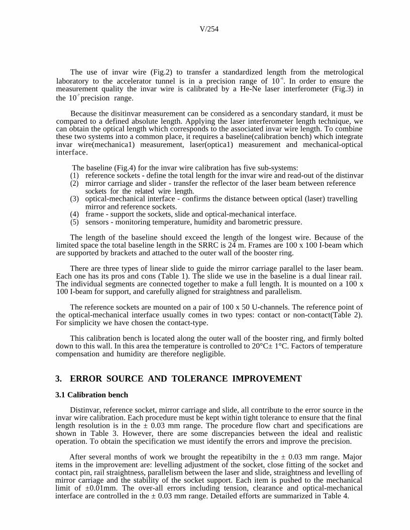
The use of invar wire (Fig.2) to transfer a standardized length from the metrologicallaboratory to the accelerator tunnel is in a precision range of 10 -6. In order to ensure themeasurement quality the invar wire is calibrated by a He-Ne laser interferometer (Fig.3) inthe 10-7 precision range.
Because the disitinvar measurement can be considered as a sencondary standard, it must becompared to a defined absolute length. Applying the laser interferometer length technique, wecan obtain the optical length which corresponds to the associated invar wire length. To combinethese two systems into a common place, it requires a baseline(calibration bench) which integrateinvar wire(mechanica1) measurement, laser(optica1) measurement and mechanical-opticalinterface.
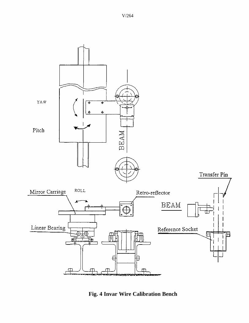
The baseline (Fig.4) for the invar wire calibration has five sub-systems:(1) reference sockets - define the total length for the invar wire and read-out of the distinvar(2) mirror carriage and slider - transfer the reflector of the laser beam between reference
sockets for the related wire length.(3) optical-mechanical interface - confirms the distance between optical (laser) travelling
mirror and reference sockets.(4)(5)
frame - support the sockets, slide and optical-mechanical interface.sensors - monitoring temperature, humidity and barometric pressure.
The length of the baseline should exceed the length of the longest wire. Because of thelimited space the total baseline length in the SRRC is 24 m. Frames are 100 x 100 I-beam whichare supported by brackets and attached to the outer wall of the booster ring.
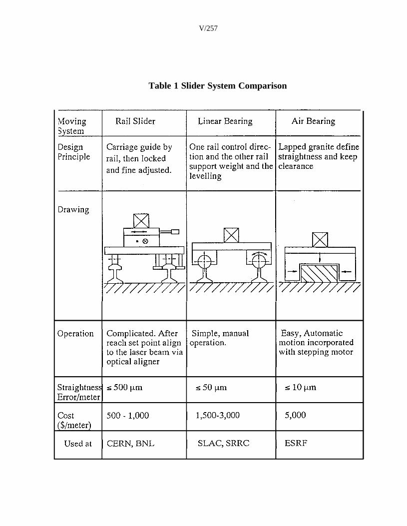
There are three types of linear slide to guide the mirror carriage parallel to the laser beam.Each one has its pros and cons (Table 1). The slide we use in the baseline is a dual linear rail.The individual segments are connected together to make a full length. It is mounted on a 100 x100 I-beam for support, and carefully aligned for straightness and parallelism.
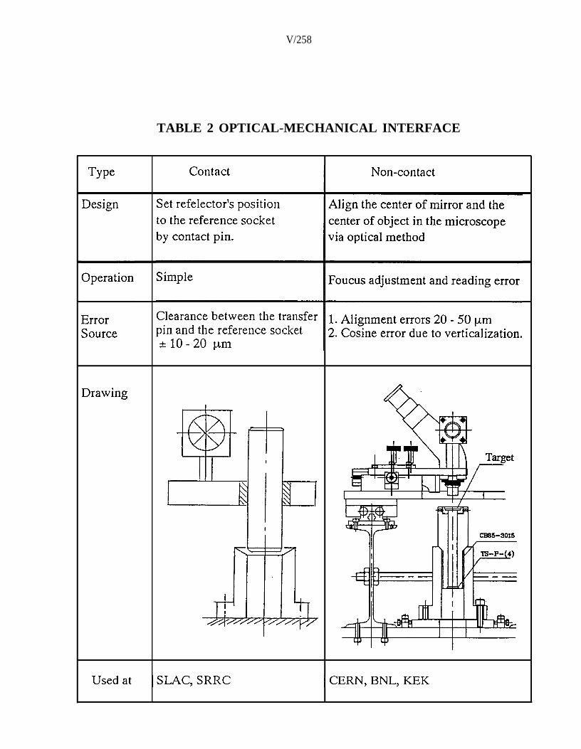
The reference sockets are mounted on a pair of 100 x 50 U-channels. The reference point ofthe optical-mechanical interface usually comes in two types: contact or non-contact(Table 2).For simplicity we have chosen the contact-type.
This calibration bench is located along the outer wall of the booster ring, and firmly bolteddown to this wall. In this area the temperature is controlled to 20°C± 1°C. Factors of temperaturecompensation and humidity are therefore negligible.
3. ERROR SOURCE AND TOLERANCE IMPROVEMENT
3.1 Calibration bench
Distinvar, reference socket, mirror carriage and slide, all contribute to the error source in theinvar wire calibration. Each procedure must be kept within tight tolerance to ensure that the finallength resolution is in the ± 0.03 mm range. The procedure flow chart and specifications areshown in Table 3. However, there are some discrepancies between the ideal and realisticoperation. To obtain the specification we must identify the errors and improve the precision.
After several months of work we brought the repeatibilty in the ± 0.03 mm range. Majoritems in the improvement are: levelling adjustment of the socket, close fitting of the socket andcontact pin, rail straightness, parallelism between the laser and slide, straightness and levelling ofmirror carriage and the stability of the socket support. Each item is pushed to the mechanicallimit of ±0.01mm. The over-all errors including tension, clearance and optical-mechanicalinterface are controlled in the ± 0.03 mm range. Detailed efforts are summarized in Table 4.

V/255
3.2 Field Operation
During field operation the major contributed error is the clearance between the referencesocket and the inserted components. We use the reference socket to represent both the fiducialpoint of the magnets and the survey position of the wall bracket and pillar. After leverage effectin the fixed poster the error is enlarged to 0.15 mm under the 15 kg tension force. The leastsqaure fitting adjustment value was 0.30 mm in the network analysis including length, angularand offset measurement. Our data shows some discrepancy between length and angularmeasurement.
To improve the measurement we made the following adjustments:(1) New and tight clearance sockets are installed to replace loose ones. However, wear-out
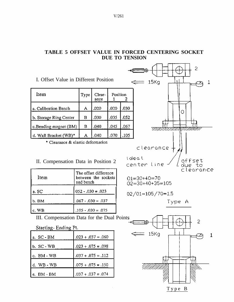
of the center hole and elastic deformation under tension has to be taken into account.(2) All local force centering offset values due to the tension force are recorded, then the
length data are compensated with offset values(Table 5). From the network analysis,overall adjustment error is within 0.10 mm range which shows good compabilitybetween length and angular measurement.
In order to ensure the quality of the length measurement, the offset values in forcedcentering sockets must be verified everytime a network survey is needed.
4. DISCUSSION
4.1 Notes on the Calibration Bench
The linear bearing slide is acceptable in the 10 -6 range in terms of economy. If higherprecision in the 10-7 range is needed for the primary baseline such as, for example, at theEuropean Synchrotron Radiation Facility (ESRF), the use of air bearings is mandatory andenvironmental control needs tight specifications. However, this makes the set-up cost extremelyhigh.
4.2 Forced Centering Socket
For the repeated measurements all the reference points must be forced centering sockets toreduce set-up errors and time. The simplified CERN type socket combines two functions: thecenter hole fit for the inserting post to guarantee the concentricity and the upper cone to confinethe center of the Talyor-Hobson sphere(Fig.5).
Two important factors must be taken into consideration:(1) Repeatability and stability - To ensure the position is not influenced by external forces
and environmental variations.(2) Clearance between matching components - The instrument or signal receiver adaptor is
attached to the socket via a centering hole or cone. If the clearance is too tight (g5/H6),it might be hard to disengage or may be frozen by external debris. On the other hand, ifthe clearance is too loose ( g6/H7 or g7/H8), the concentricity is not good enough ( r0.015 mm) and the offset is out of specification.
Using a hydraulic expansion mandrel(Fig.6) is a quick solution to overcome clearanceproblem. However, there is no thru hole in the center which limits the fixture adaptorconversion. The alternative solution is a socket with precision fitting and smooth surface toovercome this problem. When the socket is made out of aluminum the surface hardness can beimproved by hard anodizing ( 0.015 mm thickness) or electrolyzing nickel plating ( 0.02 mmthickness). The surface roughness should be specified as less than 1.5 pm. Except the offset dueto the pulling force the position error is less than the sum of the clearances between the matchingparts.

V/256
5. CONCULSION
This application is suitable for length measurement in the short range of 10 - 50 m and aresolution of ± 0.01 mm. With error compensation the accuracy of the invar wire measurementcan be kept in the ± 0.03 mm range. However, the measurement slope is limited to the 11% rangedue to distinvar constrains. The basic network of invar measurements is 2-D and can beextended to 3-D with associated leveling measurements. Small accelerators and largeconstruction works can apply invar wire techniques for space coordination and lineardeformation.
Although the 3-D laser tracking system has simple, rapid and automatic measuringcapabilities, the retro-reflector must be moved by manual or automatic operation. Therefore, theprimary application of the 3-D laser tracking system is in robot calibration. In the long run, invarwire measurement in the accelerator survey task will be replaced by the 3-D laser trackingsystem provided the retro-reflector movement can be simplified and the set-up cost madecompetitive.
ACKNOWLEDGEMENTS
I am indebted to Mr. Shi-Jou Ho for his numerous efforts to solve and improve thecalibration bench performance. Mr. Chien-Kuang Kuan and Tzu-Ying Cheng and all themembers involved in the invar wire measurement are herewith acknowledged.
REFERENCES
[1] J. Gervaise, Invar wire measurement - A Necessary Evil, CERN-SPS/SU/78-2.
[2] T. Copeland-Davis, Proc. 1st Int. workshop on Accelerator Alignment, SLAC, Stanford, CA.,USA, 1989.
[3] K. Lau et al, Automatic laser tracking interferometer system for robot metrology, PrecisionEngr, Jan. 1986.
[4] R. Gottwarld, SPACE- An Automated Non Contact 3-D Measurement System for IndustrialApplication, 7th Int. Conf. on Robot Vision and Sensory Control, Zurich, Switzerland, 1988.
[5] S. Turner, Applied Geodesy for Particle Accelerator, CERN Accelerator School, 1986.
[6] J. Baechler, Geodetic Industrielle, Vernier/Geneva, Switzerland, 1991.
V/257
Table 1 Slider System Comparison
V/258
TABLE 2 OPTICAL-MECHANICAL INTERFACE

V/259
TABLE 3 Invar Wire Calibration Procedure and Specfication

V/260
TABLE 4 Error Sources and Improvement in Bench
V/261
TABLE 5 OFFSET VALUE IN FORCED CENTERING SOCKETDUE TO TENSION
I. Offset Value in Different Position
II. Compensation Data in Position 2
III. Compensation Data for the Dual Points
T y p e B

V/262
Fig.1 The Survey Network in the Storage Ring

V/263
Fig.2 Dist invar and Invar Wire
Fig.3 Distince Measurement in Interferometer
V/264
Fig. 4 Invar Wire Calibration Bench

V/265

V/266