Invacare Mobile Recliners - MPS Home Page Recl/6074...Invacare Mobile Recliners 2 Part No. 1141494...
32
Owner’s Operation and Maintenance Manual DEALER: This manual MUST be given to the user of the product. USER: BEFORE using this product, read this manual and save for future reference. For more information regarding Invacare products, parts, and services, please visit www.invacare.com Invacare Mobile Recliners Three-Position Recliner Model IH6074A Deluxe Three-Position Recliner Model IH6065 series Clinical Recliner Model IH6077A
Transcript of Invacare Mobile Recliners - MPS Home Page Recl/6074...Invacare Mobile Recliners 2 Part No. 1141494...
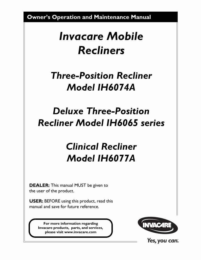
Owner’s Operation and Maintenance Manual
DEALER: This manual MUST be given to the user of the product.
USER: BEFORE using this product, read this manual and save for future reference.
For more information regarding Invacare products, parts, and services,
please visit www.invacare.com
Invacare Mobile Recliners
Three-Position Recliner Model IH6074A
Deluxe Three-Position Recliner Model IH6065 series
Clinical ReclinerModel IH6077A
Invacare Mobile Recliners 2 Part No. 1141494
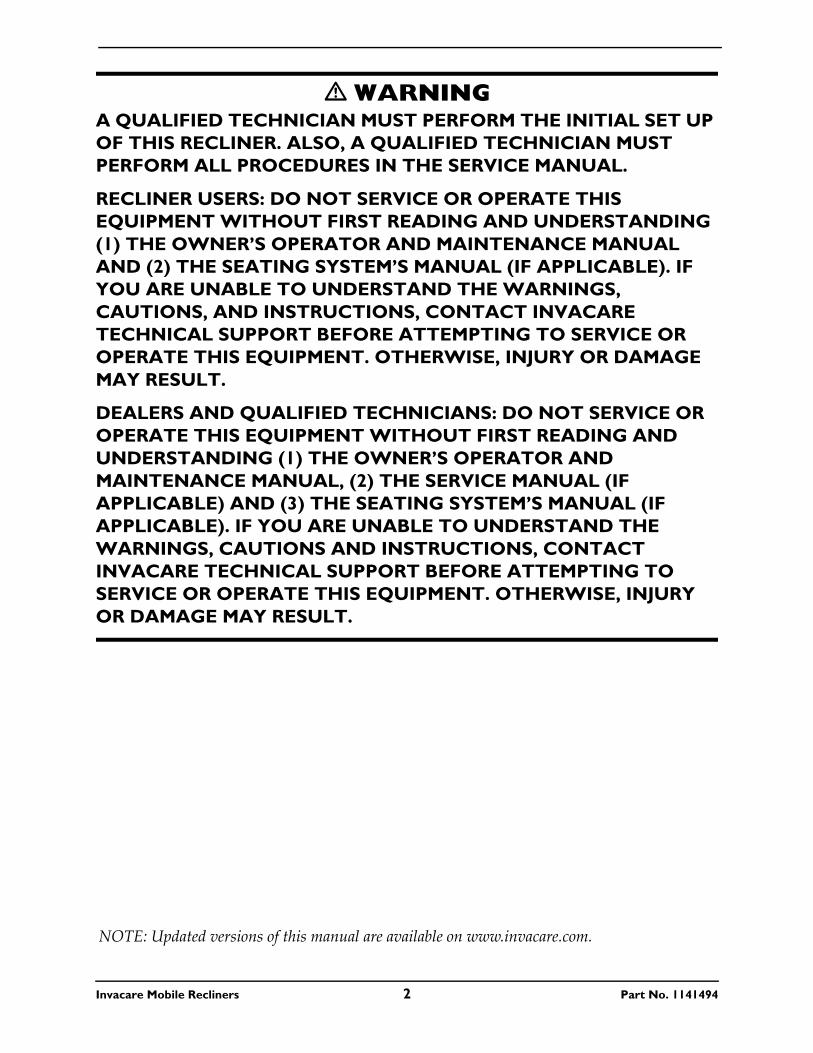
� WARNINGA QUALIFIED TECHNICIAN MUST PERFORM THE INITIAL SET UP OF THIS RECLINER. ALSO, A QUALIFIED TECHNICIAN MUST PERFORM ALL PROCEDURES IN THE SERVICE MANUAL.
RECLINER USERS: DO NOT SERVICE OR OPERATE THIS EQUIPMENT WITHOUT FIRST READING AND UNDERSTANDING (1) THE OWNER’S OPERATOR AND MAINTENANCE MANUAL AND (2) THE SEATING SYSTEM’S MANUAL (IF APPLICABLE). IF YOU ARE UNABLE TO UNDERSTAND THE WARNINGS, CAUTIONS, AND INSTRUCTIONS, CONTACT INVACARE TECHNICAL SUPPORT BEFORE ATTEMPTING TO SERVICE OR OPERATE THIS EQUIPMENT. OTHERWISE, INJURY OR DAMAGE MAY RESULT.
DEALERS AND QUALIFIED TECHNICIANS: DO NOT SERVICE OR OPERATE THIS EQUIPMENT WITHOUT FIRST READING AND UNDERSTANDING (1) THE OWNER’S OPERATOR AND MAINTENANCE MANUAL, (2) THE SERVICE MANUAL (IF APPLICABLE) AND (3) THE SEATING SYSTEM’S MANUAL (IF APPLICABLE). IF YOU ARE UNABLE TO UNDERSTAND THE WARNINGS, CAUTIONS AND INSTRUCTIONS, CONTACT INVACARE TECHNICAL SUPPORT BEFORE ATTEMPTING TO SERVICE OR OPERATE THIS EQUIPMENT. OTHERWISE, INJURY OR DAMAGE MAY RESULT.
NOTE: Updated versions of this manual are available on www.invacare.com.
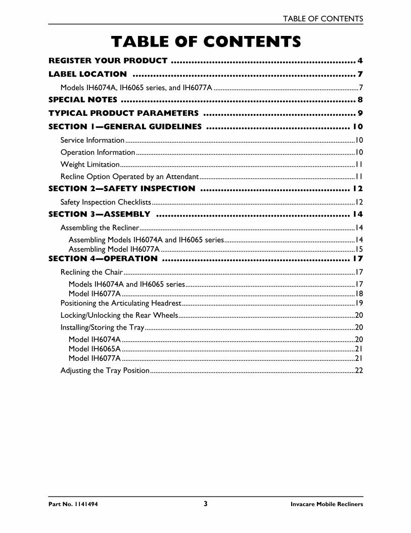
TABLE OF CONTENTS
TABLE OF CONTENTS
REGISTER YOUR PRODUCT ............................................................... 4LABEL LOCATION ............................................................................ 7
Models IH6074A, IH6065 series, and IH6077A ..................................................................................7
SPECIAL NOTES ................................................................................ 8
TYPICAL PRODUCT PARAMETERS .................................................... 9
SECTION 1—GENERAL GUIDELINES ................................................. 10
Service Information ..................................................................................................................................10
Operation Information ............................................................................................................................10
Weight Limitation.....................................................................................................................................11
Recline Option Operated by an Attendant ........................................................................................11
SECTION 2—SAFETY INSPECTION ................................................... 12
Safety Inspection Checklists ...................................................................................................................12
SECTION 3—ASSEMBLY .................................................................. 14
Assembling the Recliner..........................................................................................................................14
Assembling Models IH6074A and IH6065 series..........................................................................14Assembling Model IH6077A ..............................................................................................................15
SECTION 4—OPERATION ................................................................ 17
Reclining the Chair ...................................................................................................................................17
Models IH6074A and IH6065 series................................................................................................17Model IH6077A ....................................................................................................................................18
Positioning the Articulating Headrest..................................................................................................19
Locking/Unlocking the Rear Wheels....................................................................................................20
Installing/Storing the Tray.......................................................................................................................20
Model IH6074A ....................................................................................................................................20Model IH6065A ....................................................................................................................................21Model IH6077A ....................................................................................................................................21
Adjusting the Tray Position....................................................................................................................22
Part No. 1141494 3 Invacare Mobile Recliners
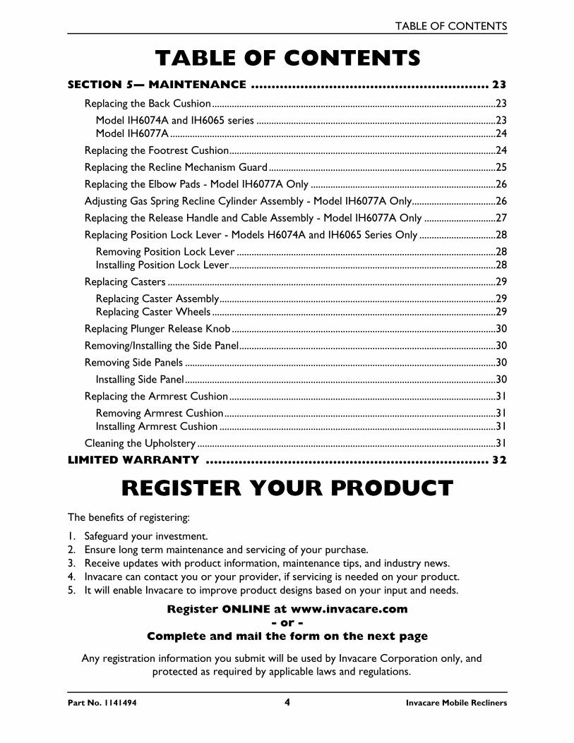
TABLE OF CONTENTS
TABLE OF CONTENTS
SECTION 5— MAINTENANCE .......................................................... 23Replacing the Back Cushion...................................................................................................................23
Model IH6074A and IH6065 series .................................................................................................23Model IH6077A ....................................................................................................................................24
Replacing the Footrest Cushion............................................................................................................24
Replacing the Recline Mechanism Guard ............................................................................................25
Replacing the Elbow Pads - Model IH6077A Only ...........................................................................26
Adjusting Gas Spring Recline Cylinder Assembly - Model IH6077A Only..................................26
Replacing the Release Handle and Cable Assembly - Model IH6077A Only .............................27
Replacing Position Lock Lever - Models H6074A and IH6065 Series Only ...............................28
Removing Position Lock Lever .........................................................................................................28Installing Position Lock Lever............................................................................................................28
Replacing Casters .....................................................................................................................................29
Replacing Caster Assembly................................................................................................................29Replacing Caster Wheels ...................................................................................................................29
Replacing Plunger Release Knob ...........................................................................................................30
Removing/Installing the Side Panel........................................................................................................30
Removing Side Panels ..............................................................................................................................30
Installing Side Panel ..............................................................................................................................30
Replacing the Armrest Cushion ............................................................................................................31
Removing Armrest Cushion..............................................................................................................31Installing Armrest Cushion ................................................................................................................31
Cleaning the Upholstery .........................................................................................................................31
LIMITED WARRANTY ..................................................................... 32
REGISTER YOUR PRODUCTThe benefits of registering:
1. Safeguard your investment.2. Ensure long term maintenance and servicing of your purchase.3. Receive updates with product information, maintenance tips, and industry news.4. Invacare can contact you or your provider, if servicing is needed on your product.5. It will enable Invacare to improve product designs based on your input and needs.
Register ONLINE at www.invacare.com- or -
Complete and mail the form on the next page
Any registration information you submit will be used by Invacare Corporation only, and protected as required by applicable laws and regulations.
Part No. 1141494 4 Invacare Mobile Recliners
Part No. 1141494 5 Invacare Mobile Recliners
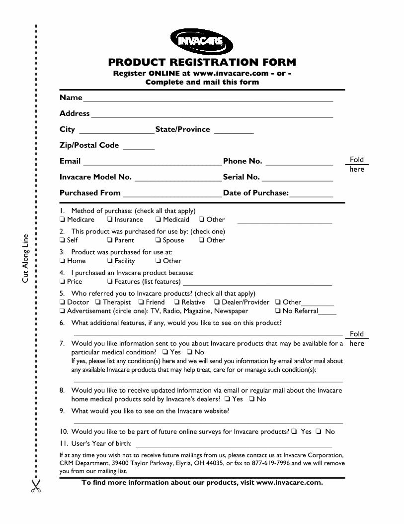
Name_______________________________________________________________
Address _____________________________________________________________
City ___________________State/Province __________
Zip/Postal Code ________
Email ___________________________________Phone No. _________________
Invacare Model No. ______________________Serial No. __________________
Purchased From _________________________Date of Purchase:___________
1. Method of purchase: (check all that apply)❏ Medicare ❏ Insurance ❏ Medicaid ❏ Other __________________________
2. This product was purchased for use by: (check one)❏ Self ❏ Parent ❏ Spouse ❏ Other
3. Product was purchased for use at:❏ Home ❏ Facility ❏ Other
4. I purchased an Invacare product because:❏ Price ❏ Features (list features) _________________________________________
5. Who referred you to Invacare products? (check all that apply)❏ Doctor ❏ Therapist ❏ Friend ❏ Relative ❏ Dealer/Provider ❏ Other_________❏ Advertisement (circle one): TV, Radio, Magazine, Newspaper ❏ No Referral_____
6. What additional features, if any, would you like to see on this product?__________________________________________________________________________
7. Would you like information sent to you about Invacare products that may be available for aparticular medical condition? ❏ Yes ❏ NoIf yes, please list any condition(s) here and we will send you information by email and/or mail aboutany available Invacare products that may help treat, care for or manage such condition(s):__________________________________________________________________________
8. Would you like to receive updated information via email or regular mail about the Invacarehome medical products sold by Invacare's dealers? ❏ Yes ❏ No
9. What would you like to see on the Invacare website?__________________________________________________________________________
10. Would you like to be part of future online surveys for Invacare products? ❏ Yes ❏ No
11. User's Year of birth: ______________________________________________________
If at any time you wish not to receive future mailings from us, please contact us at Invacare Corporation,CRM Department, 39400 Taylor Parkway, Elyria, OH 44035, or fax to 877-619-7996 and we will removeyou from our mailing list.
To find more information about our products, visit www.invacare.com.
PRODUCT REGISTRATION FORMRegister ONLINE at www.invacare.com - or -
Complete and mail this form
Cut
Alo
ng L
ine
Foldhere
Foldhere
Invacare Mobile Recliners 6 Part No. 1141494
��������
��������
�
����
���
� �
������������� ������ �� ������
������������� �������������������
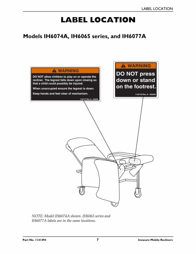
LABEL LOCATION
Part No. 1141494 7 Invacare Mobile Recliners
LABEL LOCATION
Models IH6074A, IH6065 series, and IH6077A
DO NOT allow children to play on or operate the recliner. The legrest falls down upon closing so that a child could possibly be injured.
When unoccupied ensure the legrest is down.
Keep hands and feet clear of mechanism.
1143177 Rev. A - 4/25/06
DO NOT press down or stand on the footrest.
1143178 Rev. A - 4/25/06
NOTE: Model IH6074A shown. IH6065 series and IH6077A labels are in the same locations.
SPECIAL NOTES
Invacare Mobile Recliners 8 Part No. 1141494
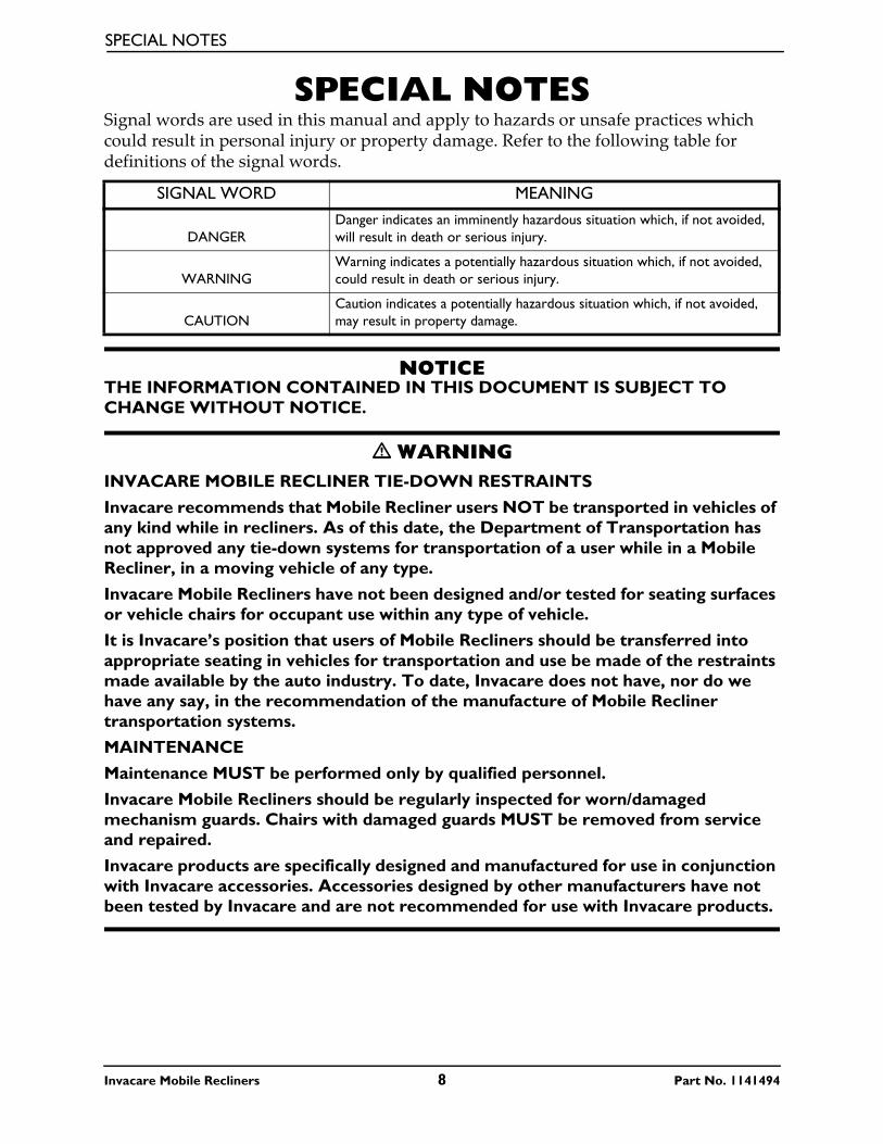
SPECIAL NOTESSignal words are used in this manual and apply to hazards or unsafe practices which could result in personal injury or property damage. Refer to the following table for definitions of the signal words.
NOTICETHE INFORMATION CONTAINED IN THIS DOCUMENT IS SUBJECT TO CHANGE WITHOUT NOTICE.
� WARNINGINVACARE MOBILE RECLINER TIE-DOWN RESTRAINTS
Invacare recommends that Mobile Recliner users NOT be transported in vehicles of any kind while in recliners. As of this date, the Department of Transportation has not approved any tie-down systems for transportation of a user while in a Mobile Recliner, in a moving vehicle of any type.
Invacare Mobile Recliners have not been designed and/or tested for seating surfaces or vehicle chairs for occupant use within any type of vehicle.
It is Invacare’s position that users of Mobile Recliners should be transferred into appropriate seating in vehicles for transportation and use be made of the restraints made available by the auto industry. To date, Invacare does not have, nor do we have any say, in the recommendation of the manufacture of Mobile Recliner transportation systems.
MAINTENANCE
Maintenance MUST be performed only by qualified personnel.
Invacare Mobile Recliners should be regularly inspected for worn/damaged mechanism guards. Chairs with damaged guards MUST be removed from service and repaired.
Invacare products are specifically designed and manufactured for use in conjunction with Invacare accessories. Accessories designed by other manufacturers have not been tested by Invacare and are not recommended for use with Invacare products.
SIGNAL WORD MEANING
DANGERDanger indicates an imminently hazardous situation which, if not avoided, will result in death or serious injury.
WARNINGWarning indicates a potentially hazardous situation which, if not avoided, could result in death or serious injury.
CAUTIONCaution indicates a potentially hazardous situation which, if not avoided, may result in property damage.
TYPICAL PRODUCT PARAMETERS
Part No. 1141494 9 Invacare Mobile Recliners
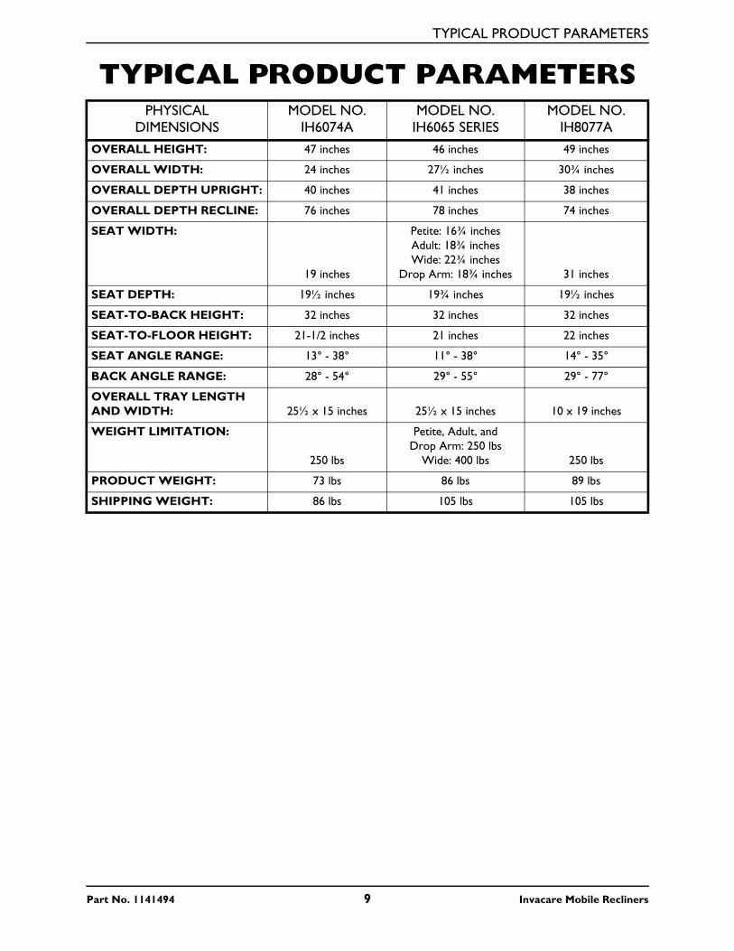
TYPICAL PRODUCT PARAMETERSPHYSICAL
DIMENSIONSMODEL NO.
IH6074AMODEL NO.
IH6065 SERIESMODEL NO.
IH8077AOVERALL HEIGHT: 47 inches 46 inches 49 inches
OVERALL WIDTH: 24 inches 27½ inches 30¾ inches
OVERALL DEPTH UPRIGHT: 40 inches 41 inches 38 inches
OVERALL DEPTH RECLINE: 76 inches 78 inches 74 inches
SEAT WIDTH:
19 inches
Petite: 16¾ inchesAdult: 18¾ inchesWide: 22¾ inches
Drop Arm: 18¾ inches 31 inches
SEAT DEPTH: 19½ inches 19¾ inches 19½ inches
SEAT-TO-BACK HEIGHT: 32 inches 32 inches 32 inches
SEAT-TO-FLOOR HEIGHT: 21-1/2 inches 21 inches 22 inches
SEAT ANGLE RANGE: 13° - 38° 11° - 38° 14° - 35°
BACK ANGLE RANGE: 28° - 54° 29° - 55° 29° - 77°
OVERALL TRAY LENGTH AND WIDTH: 25½ x 15 inches 25½ x 15 inches 10 x 19 inches
WEIGHT LIMITATION:
250 lbs
Petite, Adult, and Drop Arm: 250 lbs
Wide: 400 lbs 250 lbs
PRODUCT WEIGHT: 73 lbs 86 lbs 89 lbs
SHIPPING WEIGHT: 86 lbs 105 lbs 105 lbs
SECTION 1—GENERAL GUIDELINES
SECTION 1—GENERAL GUIDELINES
� WARNINGSECTION 1 - GENERAL GUIDELINES contains important information for the safe operation and use of this product. DO NOT use this product or any available optional equipment without first completely reading and understanding these instructions and any additional instructional material such as Owner’s Manuals, Service Manuals or Instruction Sheets supplied with this product or optional equipment. If you are unable to understand the Warnings, Cautions or Instructions, contact a healthcare professional, dealer or technical personnel before attempting to use this equipment - otherwise, injury or damage may occur.
Service InformationAfter the first six months of operation, inspect all pivot points and fasteners for wear. If the metal is worn, the parts MUST be replaced. Make this inspection every six months thereafter.
Regular maintenance of the mobile recliner and accessories is necessary to assure proper operation.
Operation InformationCheck all parts for shipping damage. In case of damage, DO NOT use. Contact Carrier/Dealer for further instructions.
ALWAYS keep hands and fingers clear of moving parts to avoid injury.
DO NOT use near an open flame or heat source, as all upholstery materials, even though treated with flame retardant, can ignite when exposed to open flame.
Rear caster wheels MUST be locked during user transfer to or from recliner and while tilting and/or reclining or inclining (sitting up).
Ensure that casters are free of debris.
Casters and axle bolts require inspection every six months to check for tightness and wear.
DO NOT enter or exit the recliner when footrest is elevated.
DO NOT sit on the footrest when recliner is extended. The recliner will tip and bodily injury may occur.
DO NOT push or pull footrest to position the recliner.
DO NOT place hands or feet into any openings when adjusting the recliner. Attendant or care provider should always verify placement of user’s hands and feet prior to adjusting the recliner. Failure to do so may result in serious bodily injury.
Invacare Mobile Recliners 10 Part No. 1141494
SECTION 1—GENERAL GUIDELINES
Operation of recliner with missing or broken footrest or recline mechanism guards may result in bodily injury. Periodic inspection of the footrest guard and recline mechanism guard MUST be made four times a year. Torn, cracked or otherwise damaged guards MUST be replaced prior to use. Recliner MUST be removed from service until replacement guards are installed.
DO NOT lift the recliner by the footrest. Lifting by means of the footrest may result in injury to the user and/or damage to the recliner.
DO NOT attempt to stop the recliner with the wheel locks, while in motion. Wheel locks are not brakes.
Before attempting to transfer in or out of the recliner, every precaution should be taken to reduce the gap distance. Turn the recliner toward the object you are transferring onto. When transferring to and from the recliner, ALWAYS engage both wheel locks. Special care MUST BE taken with people that have physical limitations which may require an assistant.
DO NOT traverse, climb or go down ramps or slopes greater than 9°.
Invacare products are specifically designed and manufactured for use in conjunction with Invacare accessories. Accessories designed by other manufacturers have not been tested by Invacare and are not recommended for use with Invacare products.
Weight LimitationThe weight limitation for Invacare Mobile Recliners is 250 lbs (113.6 kg). The weight limitation for model IH6065WD Wide Recliner is 400 lbs (181.44 kg).
The tray for models IH6074A, IH6065A, and IH6077A has a weight limitation of 40 lbs (18.2 kg).
Recline Option Operated by an AttendantTest the recline feature of the recliner first without an occupant to ensure the gas cylinder is operational. DO NOT operate the recline option if the gas cylinder is not operational.
ALWAYS make sure that the recliner is stable before using the recline option.
Make sure the patient is properly positioned in the recliner before reclining or inclining to maintain maximum stability and safety.
When returning the occupant of the recliner to the full upright position, more body strength will be required for approximately the last twenty degrees of incline (sitting up). Make sure to use proper body mechanics (use your legs) or seek assistance to avoid injury.
Physical limitations of a user and larger occupants of the recliner can present conditions that can injure the assistant. When in doubt, assure that additional assistants are present before operating the recline feature.
Part No. 1141494 11 Invacare Mobile Recliners
SECTION 2—SAFETY INSPECTION
SECTION 2—SAFETY INSPECTIONNOTE: Every six months or as necessary take your recliner to a qualified dealer for a thorough inspection and servicing. Regular cleaning will reveal loose or worn parts and enhance the smooth operation of your recliner. To operate properly and safely, your recliner must be cared for appropriately as any other vehicle. Routine maintenance will extend the life and efficiency of your recliner.
Safety Inspection Checklists
CAUTIONAs with any transport device, casters should be checked periodically for cracks and wear and should be replaced as necessary.
Initial adjustments should be made to suit your personal body structure needs and preference. Thereafter follow these maintenance procedures:
Inspect/Adjust Initially
❑ Ensure that the recliner rolls straight (no excessive drag or pull to one side).
❑ Ensure seat, back and/or armrest upholstery have no rips and do not sag. Replace if necessary.
❑ Ensure that the seat upholstery is fastened to the seat frame.
❑ Clean seat upholstery and armrests.
❑ Inspect caster assembly to ensure it has proper tension when caster is spun. Caster should come to a gradual stop.
❑ Loosen/tighten caster locknut if wheel wobbles noticeably or binds to a stop.
❑ Ensure that the caster assembly is free from debris.
❑ Inspect for any loose hardware on the recliner.
❑ Check that all labels are present and legible. Replace if necessary.
❑ FOR IH6077A ONLY - Ensure that the trigger release cables completely release and the handles return when released.
❑ FOR IH6077A ONLY - Inspect the gas cylinders for leaking oil.
Inspect/Adjust Weekly
❑ Ensure that the seat upholstery is fastened to the seat frame.
❑ Ensure seat, back and/or armrest upholstery have no rips and do not sag. Replace if necessary.
❑ Ensure that the caster assembly is free of debris.
Invacare Mobile Recliners 12 Part No. 1141494
SECTION 2—SAFETY INSPECTION
❑ FOR IH6077A ONLY - Ensure that the trigger release cables completely release and the handles return when released.
Inspect/Adjust Monthly
❑ Ensure that the recliner rolls straight (no excessive drag or pull to one side).
❑ Ensure that the seat upholstery is fastened to the seat frame.
❑ Inspect caster assembly to ensure it has proper tension when caster is spun. Caster should come to a gradual stop.
❑ Loosen/tighten caster locknut if wheel wobbles noticeably or binds to a stop.
❑ Inspect for any loose hardware on the recliner.
❑ FOR IH6077A ONLY - Ensure that the trigger releae cables completely release and the handles return when released.
Inspect/Adjust Periodically
❑ Ensure recliner rolls straight (no excessive drag or pull to one side).
❑ Ensure seat, back and/or armrest upholstery have no rips and do not sag. Replace if necessary.
❑ Clean upholstery and armrests.
❑ Check that all labels are present and legible. Replace if necessary.
❑ FOR IH6077A ONLY - Inspect the gas cylinders for leaking oil.
Part No. 1141494 13 Invacare Mobile Recliners

SECTION 3—ASSEMBLY
SECTION 3—ASSEMBLY
� WARNINGAfter ANY adjustments, repair or service and before use, make sure that all attach-ing hardware is tightened securely - otherwise injury or damage may result.
Assembling the Recliner
� WARNINGTighten mounting screws securely. Failure to do so may result in bodily injury or damage to the recliner.
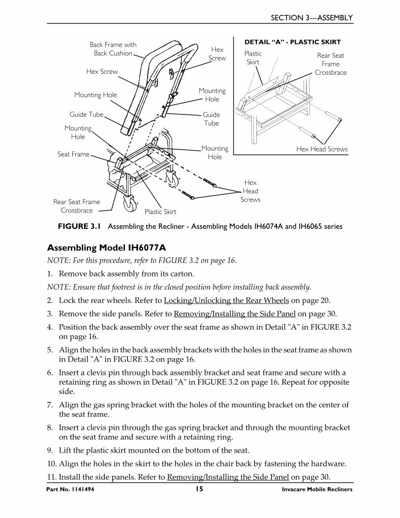
Assembling Models IH6074A and IH6065 series NOTE: For this procedure, refer to FIGURE 3.1 on page 15.
1. Remove back frame with back cushion from its carton.
2. Lock the rear casters. Work from the rear of the recliner base.
NOTE: Ensure that footrest is in closed position before installing the back frame with cushion.
3. Lift the chair back in an upright position behind the rear seat cross brace.
4. Slide the back tubes into the open tube ends of the rear seat cross brace.
5. Lift the plastic skirt mounted on the bottom of the seat and align behind the rear seat frame crossbrace (Detail “A”).
6. Align the holes in the skirt to the holes in the chair back by fastening the hardware.
7. Securely tighten the two hex screws to secure the back cushion to the back frame.
Invacare Mobile Recliners 14 Part No. 1141494
SECTION 3—ASSEMBLY
FIGURE 3.1 Assembling the Recliner - Assembling Models IH6074A and IH6065 series
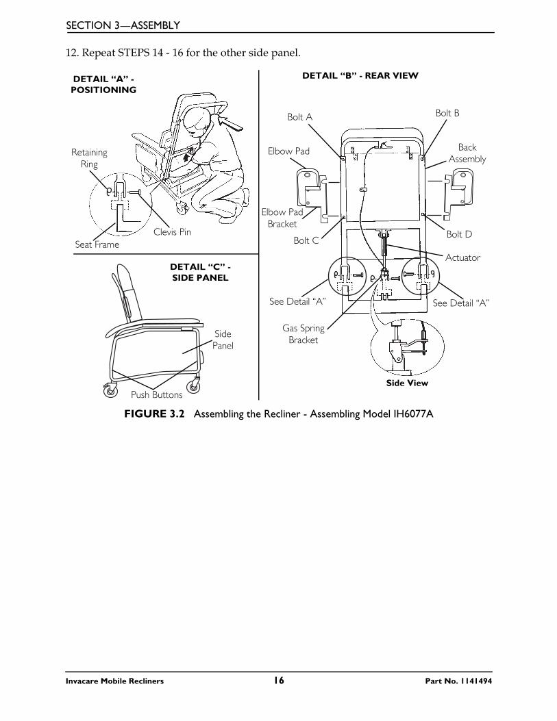
Assembling Model IH6077ANOTE: For this procedure, refer to FIGURE 3.2 on page 16.
1. Remove back assembly from its carton.
NOTE: Ensure that footrest is in the closed position before installing back assembly.
2. Lock the rear wheels. Refer to Locking/Unlocking the Rear Wheels on page 20.
3. Remove the side panels. Refer to Removing/Installing the Side Panel on page 30.
4. Position the back assembly over the seat frame as shown in Detail ʺAʺ in FIGURE 3.2 on page 16.
5. Align the holes in the back assembly brackets with the holes in the seat frame as shown in Detail ʺAʺ in FIGURE 3.2 on page 16.
6. Insert a clevis pin through back assembly bracket and seat frame and secure with a retaining ring as shown in Detail ʺAʺ in FIGURE 3.2 on page 16. Repeat for opposite side.
7. Align the gas spring bracket with the holes of the mounting bracket on the center of the seat frame.
8. Insert a clevis pin through the gas spring bracket and through the mounting bracket on the seat frame and secure with a retaining ring.
9. Lift the plastic skirt mounted on the bottom of the seat.
10. Align the holes in the skirt to the holes in the chair back by fastening the hardware.
11. Install the side panels. Refer to Removing/Installing the Side Panel on page 30.
Back Frame with Back Cushion
Hex Screw
Mounting Hole
Guide Tube
Mounting Hole
Seat Frame
Rear Seat Frame Crossbrace
Hex Head
Screws
Mounting Hole
Guide Tube
Mounting Hole
Hex Screw
Plastic Skirt
Hex Head Screws
Plastic Skirt
Rear Seat Frame
Crossbrace
DETAIL “A” - PLASTIC SKIRT
Part No. 1141494 15 Invacare Mobile Recliners
SECTION 3—ASSEMBLY
12. Repeat STEPS 14 - 16 for the other side panel.
FIGURE 3.2 Assembling the Recliner - Assembling Model IH6077A
DETAIL “A” - POSITIONING
DETAIL “B” - REAR VIEW
DETAIL “C” - SIDE PANEL
Retaining Ring
Clevis PinSeat Frame
Push Buttons
Side Panel
Back Assembly
Bolt DBolt C
Elbow Pad
Elbow Pad Bracket
Actuator
Gas Spring Bracket
Side View
See Detail “A” See Detail “A”
Bolt A Bolt B
Invacare Mobile Recliners 16 Part No. 1141494
SECTION 4—OPERATION
SECTION 4—OPERATION
� WARNINGAfter ANY adjustments, repair or service and BEFORE use, make sure that all attaching hardware is tightened securely - otherwise injury or damage may result.
CAUTIONEnsure that there is adequate room to operate the Invacare Mobile Recliner. There must be at least three feet clearance between the top of the recliner back and the surrounding objects, otherwise damage to the recliner and or surrounding property may occur.
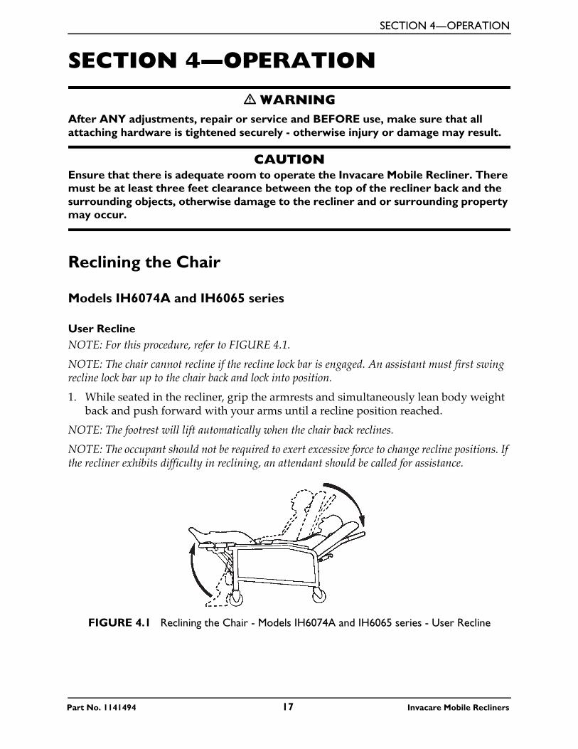
Reclining the Chair
Models IH6074A and IH6065 series
User ReclineNOTE: For this procedure, refer to FIGURE 4.1.
NOTE: The chair cannot recline if the recline lock bar is engaged. An assistant must first swing recline lock bar up to the chair back and lock into position.
1. While seated in the recliner, grip the armrests and simultaneously lean body weight back and push forward with your arms until a recline position reached.
NOTE: The footrest will lift automatically when the chair back reclines.
NOTE: The occupant should not be required to exert excessive force to change recline positions. If the recliner exhibits difficulty in reclining, an attendant should be called for assistance.
FIGURE 4.1 Reclining the Chair - Models IH6074A and IH6065 series - User Recline
Part No. 1141494 17 Invacare Mobile Recliners
SECTION 4—OPERATION
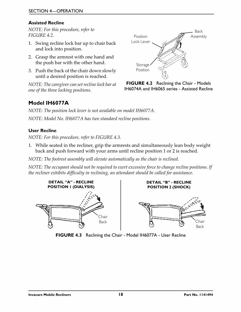
Assisted ReclineNOTE: For this procedure, refer to FIGURE 4.2.
1. Swing recline lock bar up to chair back and lock into position.
2. Grasp the armrest with one hand and the push bar with the other hand.
3. Push the back of the chair down slowly until a desired position is reached.
NOTE: The caregiver can set recline lock bar at one of the three locking positions.
FIGURE 4.2 Reclining the Chair - Models IH6074A and IH6065 series - Assisted Recline
Model IH6077ANOTE: The position lock lever is not available on model IH6077A.
NOTE: Model No. IH6077A has two standard recline positions.
User ReclineNOTE: For this procedure, refer to FIGURE 4.3.
1. While seated in the recliner, grip the armrests and simultaneously lean body weight back and push forward with your arms until recline position 1 or 2 is reached.
NOTE: The footrest assembly will elevate automatically as the chair is reclined.
NOTE: The occupant should not be required to exert excessive force to change recline positions. If the recliner exhibits difficulty in reclining, an attendant should be called for assistance.
FIGURE 4.3 Reclining the Chair - Model IH6077A - User Recline
Back Assembly
Storage Position
Position Lock Lever
DETAIL “A” - RECLINE POSITION 1 (DIALYSIS)
DETAIL “B” - RECLINE POSITION 2 (SHOCK)
Chair Back Chair
Back
Invacare Mobile Recliners 18 Part No. 1141494
SECTION 4—OPERATION
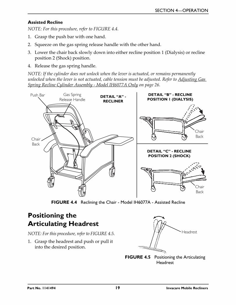
Assisted ReclineNOTE: For this procedure, refer to FIGURE 4.4.
1. Grasp the push bar with one hand.
2. Squeeze on the gas spring release handle with the other hand.
3. Lower the chair back slowly down into either recline position 1 (Dialysis) or recline position 2 (Shock) position.
4. Release the gas spring handle.
NOTE: If the cylinder does not unlock when the lever is actuated, or remains permanently unlocked when the lever is not actuated, cable tension must be adjusted. Refer to Adjusting Gas Spring Recline Cylinder Assembly - Model IH6077A Only on page 26.
FIGURE 4.4 Reclining the Chair - Model IH6077A - Assisted Recline
Positioning the Articulating HeadrestNOTE: For this procedure, refer to FIGURE 4.5.
1. Grasp the headrest and push or pull it into the desired position.
FIGURE 4.5 Positioning the Articulating Headrest
DETAIL “B” - RECLINE POSITION 1 (DIALYSIS)
DETAIL “C” - RECLINE POSITION 2 (SHOCK)
Gas Spring Release Handle
Push Bar
Chair Back
Chair Back
Chair Back
DETAIL “A” - RECLINER
Headrest
Part No. 1141494 19 Invacare Mobile Recliners
SECTION 4—OPERATION
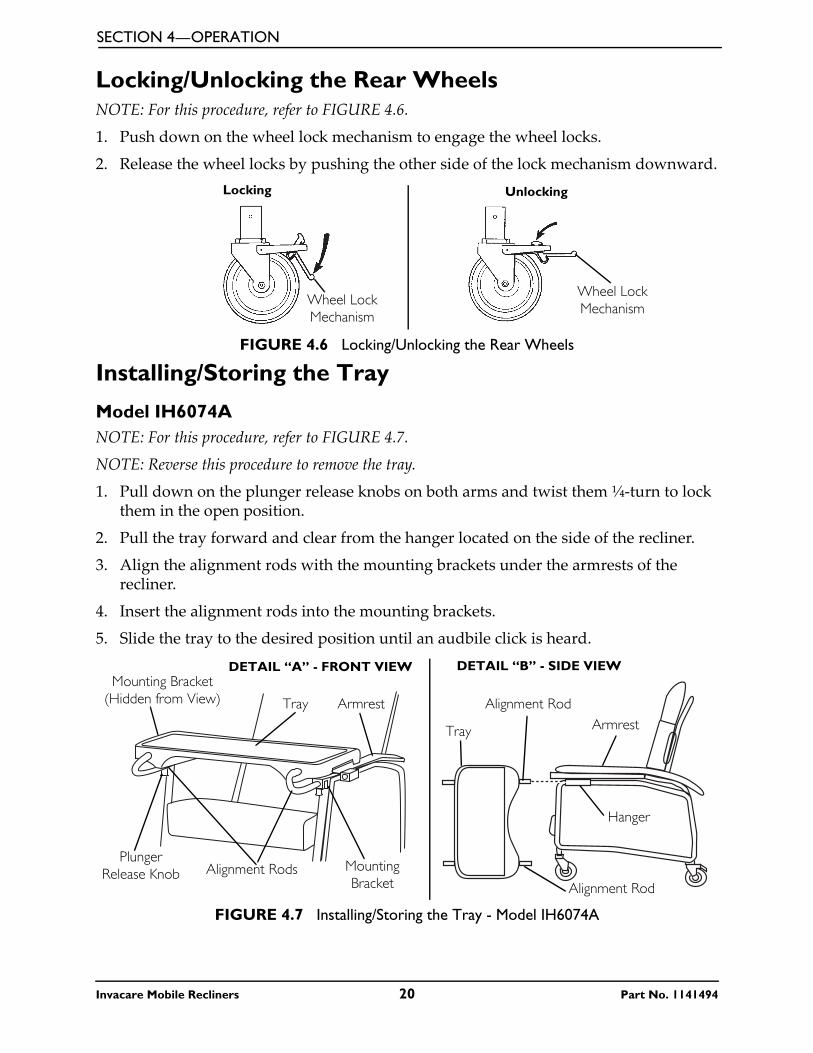
Locking/Unlocking the Rear WheelsNOTE: For this procedure, refer to FIGURE 4.6.
1. Push down on the wheel lock mechanism to engage the wheel locks.
2. Release the wheel locks by pushing the other side of the lock mechanism downward.
FIGURE 4.6 Locking/Unlocking the Rear Wheels
Installing/Storing the Tray
Model IH6074ANOTE: For this procedure, refer to FIGURE 4.7.
NOTE: Reverse this procedure to remove the tray.
1. Pull down on the plunger release knobs on both arms and twist them ¼-turn to lock them in the open position.
2. Pull the tray forward and clear from the hanger located on the side of the recliner.
3. Align the alignment rods with the mounting brackets under the armrests of the recliner.
4. Insert the alignment rods into the mounting brackets.
5. Slide the tray to the desired position until an audbile click is heard.
FIGURE 4.7 Installing/Storing the Tray - Model IH6074A
Locking Unlocking
Wheel Lock Mechanism
Wheel Lock Mechanism
Plunger Release Knob
Tray
Hanger
Tray
Mounting Bracket
Mounting Bracket (Hidden from View) Armrest
Armrest
Alignment RodsAlignment Rod
Alignment Rod
DETAIL “B” - SIDE VIEWDETAIL “A” - FRONT VIEW
Invacare Mobile Recliners 20 Part No. 1141494
SECTION 4—OPERATION
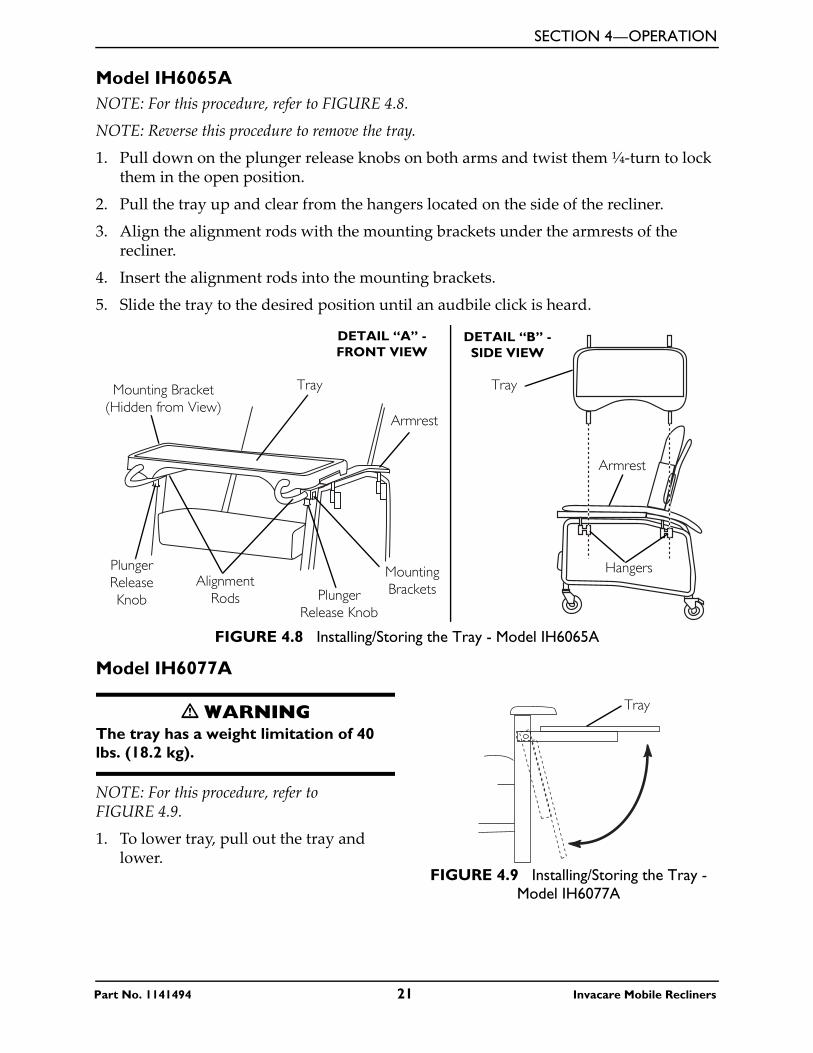
Model IH6065ANOTE: For this procedure, refer to FIGURE 4.8.
NOTE: Reverse this procedure to remove the tray.
1. Pull down on the plunger release knobs on both arms and twist them ¼-turn to lock them in the open position.
2. Pull the tray up and clear from the hangers located on the side of the recliner.
3. Align the alignment rods with the mounting brackets under the armrests of the recliner.
4. Insert the alignment rods into the mounting brackets.
5. Slide the tray to the desired position until an audbile click is heard.
FIGURE 4.8 Installing/Storing the Tray - Model IH6065A
Model IH6077A
� WARNINGThe tray has a weight limitation of 40 lbs. (18.2 kg).
NOTE: For this procedure, refer to FIGURE 4.9.
1. To lower tray, pull out the tray and lower.
FIGURE 4.9 Installing/Storing the Tray - Model IH6077A
DETAIL “B” - SIDE VIEW
DETAIL “A” - FRONT VIEW
Plunger Release Knob
Tray
Mounting Brackets
Mounting Bracket (Hidden from View)
Armrest
Alignment Rods Plunger
Release Knob
Tray
Armrest
Hangers
Tray
Part No. 1141494 21 Invacare Mobile Recliners
SECTION 4—OPERATION
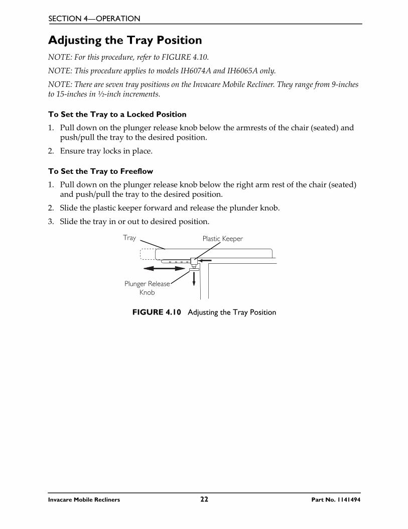
Adjusting the Tray PositionNOTE: For this procedure, refer to FIGURE 4.10.
NOTE: This procedure applies to models IH6074A and IH6065A only.
NOTE: There are seven tray positions on the Invacare Mobile Recliner. They range from 9-inches to 15-inches in ½-inch increments.
To Set the Tray to a Locked Position
1. Pull down on the plunger release knob below the armrests of the chair (seated) and push/pull the tray to the desired position.
2. Ensure tray locks in place.
To Set the Tray to Freeflow
1. Pull down on the plunger release knob below the right arm rest of the chair (seated) and push/pull the tray to the desired position.
2. Slide the plastic keeper forward and release the plunder knob.
3. Slide the tray in or out to desired position.
FIGURE 4.10 Adjusting the Tray Position
Plunger Release Knob
Plastic KeeperTray
Invacare Mobile Recliners 22 Part No. 1141494
SECTION 5—MAINTENANCE
SECTION 5— MAINTENANCE
� WARNINGAfter ANY adjustments, repair or service and BEFORE use, make sure that all attaching hardware is tightened securely - otherwise injury or damage may result.
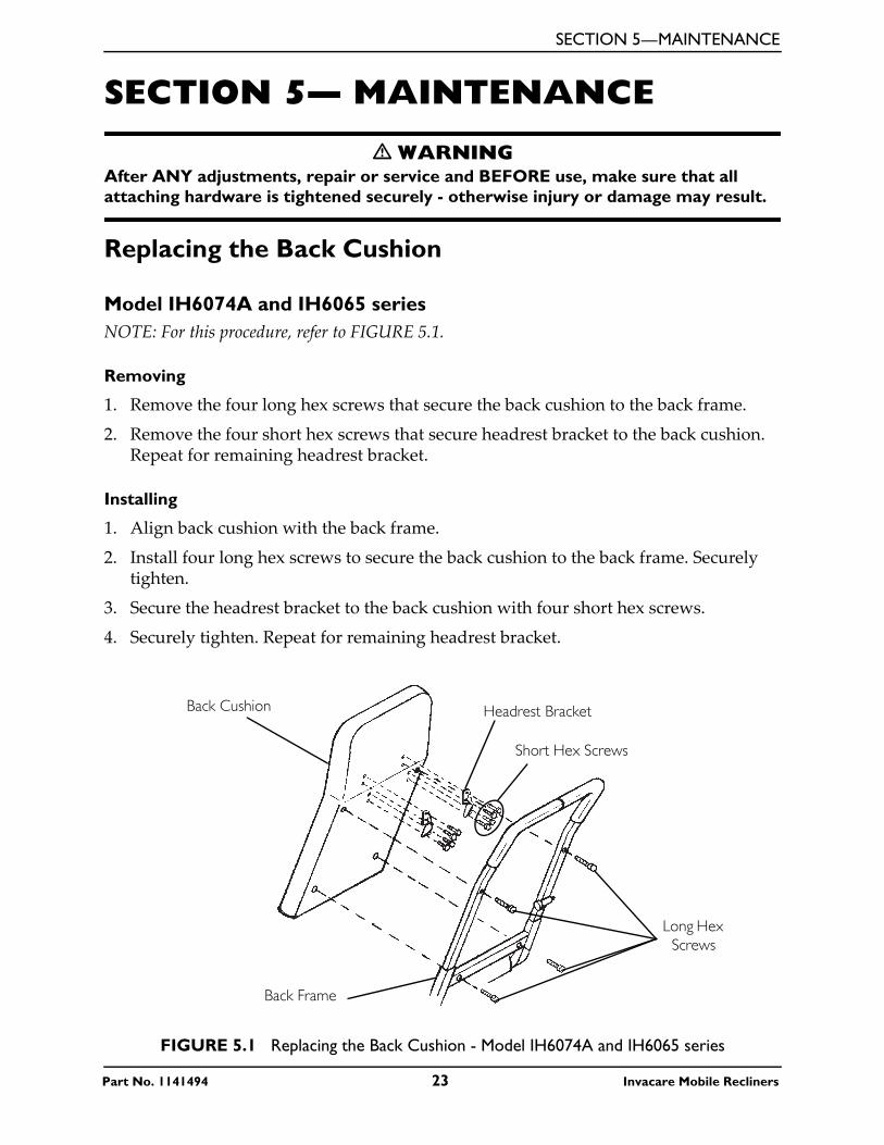
Replacing the Back Cushion
Model IH6074A and IH6065 seriesNOTE: For this procedure, refer to FIGURE 5.1.
Removing
1. Remove the four long hex screws that secure the back cushion to the back frame.
2. Remove the four short hex screws that secure headrest bracket to the back cushion. Repeat for remaining headrest bracket.
Installing
1. Align back cushion with the back frame.
2. Install four long hex screws to secure the back cushion to the back frame. Securely tighten.
3. Secure the headrest bracket to the back cushion with four short hex screws.
4. Securely tighten. Repeat for remaining headrest bracket.
FIGURE 5.1 Replacing the Back Cushion - Model IH6074A and IH6065 series
Back Cushion Headrest Bracket
Short Hex Screws
Long Hex Screws
Back Frame
Part No. 1141494 23 Invacare Mobile Recliners

SECTION 5—MAINTENANCE
Model IH6077ANOTE: For this procedure, refer to FIGURE 5.2.
Removing
1. Remove the pan head mounting screw that secures the recline cable to the existing back cushion.
2. Remove the four long hex head screws that secure the back cushion to the back frame.
3. Remove the four short hex head screws from each of the two headrest brackets.
NOTE: Reinstall the pan head mounting screw on the new back cushion assembly in approximately the same location as on the old back assembly.
Installing
1. Align new back cushion with seat and frame.
2. Install four long hex screws to secure the back cushion to the back frame as shown in FIGURE 2. Securely tighten.
3. Secure the headrest bracket to the back cushion with four short hex screws. Securely tighten.
FIGURE 5.2 Replacing the Back Cushion - Model IH6077A
Replacing the Footrest Cushion
� WARNINGDO NOT stand on the footrest or seat when entering or exiting the recliner. The recliner will tip and bodily injury may occur.
NOTE: For this procedure, refer to FIGURE 5.3 on page 25.
Headrest Bracket
Push Handle
Back Frame
Long Hex Screws
Pan Head Mounting Screw
Long Hex Screws
Short Hex Screws
Back Cushion
Invacare Mobile Recliners 24 Part No. 1141494
SECTION 5—MAINTENANCE
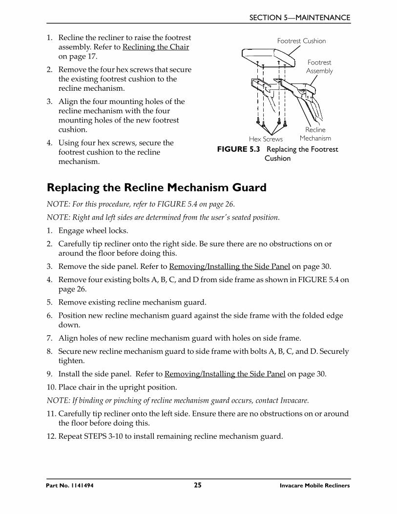
1. Recline the recliner to raise the footrest assembly. Refer to Reclining the Chair on page 17.
2. Remove the four hex screws that secure the existing footrest cushion to the recline mechanism.
3. Align the four mounting holes of the recline mechanism with the four mounting holes of the new footrest cushion.
4. Using four hex screws, secure the footrest cushion to the recline mechanism.
FIGURE 5.3 Replacing the Footrest Cushion
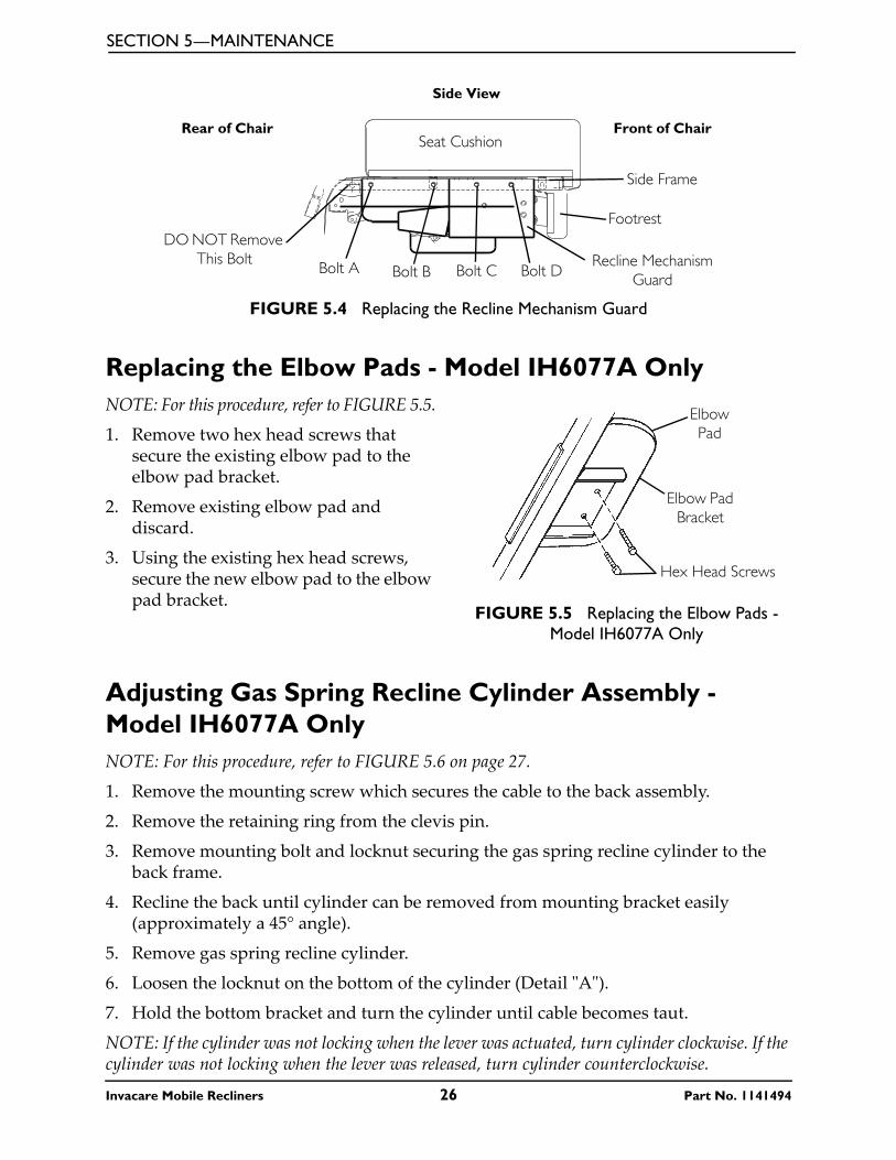
Replacing the Recline Mechanism GuardNOTE: For this procedure, refer to FIGURE 5.4 on page 26.
NOTE: Right and left sides are determined from the userʹs seated position.
1. Engage wheel locks.
2. Carefully tip recliner onto the right side. Be sure there are no obstructions on or around the floor before doing this.
3. Remove the side panel. Refer to Removing/Installing the Side Panel on page 30.
4. Remove four existing bolts A, B, C, and D from side frame as shown in FIGURE 5.4 on page 26.
5. Remove existing recline mechanism guard.
6. Position new recline mechanism guard against the side frame with the folded edge down.
7. Align holes of new recline mechanism guard with holes on side frame.
8. Secure new recline mechanism guard to side frame with bolts A, B, C, and D. Securely tighten.
9. Install the side panel. Refer to Removing/Installing the Side Panel on page 30.
10. Place chair in the upright position.
NOTE: If binding or pinching of recline mechanism guard occurs, contact Invacare.
11. Carefully tip recliner onto the left side. Ensure there are no obstructions on or around the floor before doing this.
12. Repeat STEPS 3-10 to install remaining recline mechanism guard.
Hex Screws
Footrest Cushion
Footrest Assembly
Recline Mechanism
Part No. 1141494 25 Invacare Mobile Recliners
SECTION 5—MAINTENANCE
FIGURE 5.4 Replacing the Recline Mechanism Guard
Replacing the Elbow Pads - Model IH6077A OnlyNOTE: For this procedure, refer to FIGURE 5.5.
1. Remove two hex head screws that secure the existing elbow pad to the elbow pad bracket.
2. Remove existing elbow pad and discard.
3. Using the existing hex head screws, secure the new elbow pad to the elbow pad bracket.
FIGURE 5.5 Replacing the Elbow Pads - Model IH6077A Only
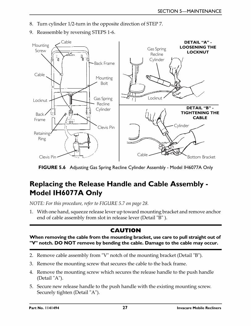
Adjusting Gas Spring Recline Cylinder Assembly - Model IH6077A OnlyNOTE: For this procedure, refer to FIGURE 5.6 on page 27.
1. Remove the mounting screw which secures the cable to the back assembly.
2. Remove the retaining ring from the clevis pin.
3. Remove mounting bolt and locknut securing the gas spring recline cylinder to the back frame.
4. Recline the back until cylinder can be removed from mounting bracket easily (approximately a 45° angle).
5. Remove gas spring recline cylinder.
6. Loosen the locknut on the bottom of the cylinder (Detail ʺAʺ).
7. Hold the bottom bracket and turn the cylinder until cable becomes taut.
NOTE: If the cylinder was not locking when the lever was actuated, turn cylinder clockwise. If the cylinder was not locking when the lever was released, turn cylinder counterclockwise.
DO NOT Remove This Bolt
Bolt A Bolt B Bolt C Bolt DRecline Mechanism
Guard
Footrest
Side Frame
Seat CushionRear of Chair
Side View
Front of Chair
Hex Head Screws
Elbow Pad Bracket
Elbow Pad
Invacare Mobile Recliners 26 Part No. 1141494
SECTION 5—MAINTENANCE
8. Turn cylinder 1/2-turn in the opposite direction of STEP 7.
9. Reassemble by reversing STEPS 1-6.
FIGURE 5.6 Adjusting Gas Spring Recline Cylinder Assembly - Model IH6077A Only
Replacing the Release Handle and Cable Assembly - Model IH6077A OnlyNOTE: For this procedure, refer to FIGURE 5.7 on page 28.
1. With one hand, squeeze release lever up toward mounting bracket and remove anchor end of cable assembly from slot in release lever (Detail ʺBʺ ).
CAUTIONWhen removing the cable from the mounting bracket, use care to pull straight out of "V" notch. DO NOT remove by bending the cable. Damage to the cable may occur.
2. Remove cable assembly from ʺVʺ notch of the mounting bracket (Detail ʺBʺ).
3. Remove the mounting screw that secures the cable to the back frame.
4. Remove the mounting screw which secures the release handle to the push handle (Detail ʺAʺ).
5. Secure new release handle to the push handle with the existing mounting screw. Securely tighten (Detail ʺAʺ).
DETAIL “B” - TIGHTENING THE
CABLE
DETAIL “A” - LOOSENING THE
LOCKNUTGas Spring
Recline Cylinder
Locknut
Bottom Bracket
Cylinder
CableClevis Pin
Clevis Pin
Gas Spring Recline Cylinder
Mounting Bolt
Back Frame
CableMounting
Screw
Cable
Locknut
Back Frame
Retaining Ring
Part No. 1141494 27 Invacare Mobile Recliners
SECTION 5—MAINTENANCE
6. Insert new cable assembly into ʺVʺ notch of the mounting bracket (Detail ʺBʺ).
7. Squeeze release lever up toward the mounting bracket and insert anchor end of new cable assembly into slot of release lever (Detail ʺBʺ).
8. Secure the cable assembly to the back frame with mounting screw. Securely tighten.
FIGURE 5.7 Replacing the Release Handle and Cable Assembly - Model IH6077A Only
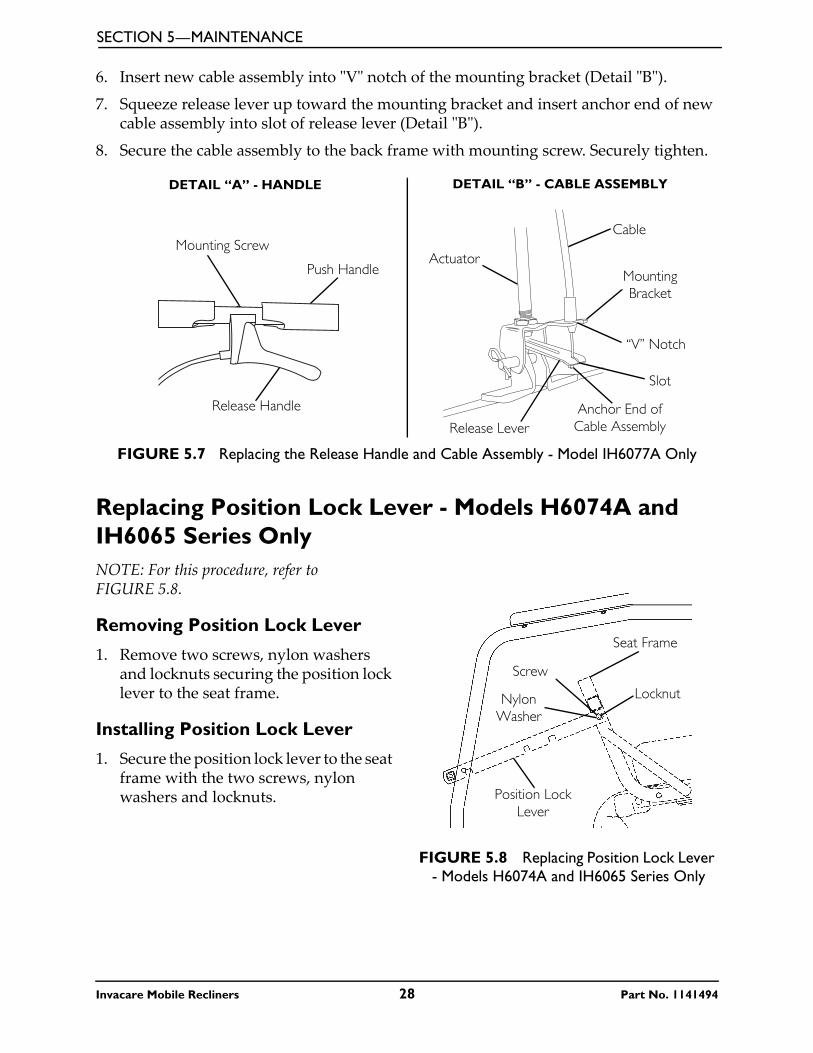
Replacing Position Lock Lever - Models H6074A and IH6065 Series OnlyNOTE: For this procedure, refer to FIGURE 5.8.
Removing Position Lock Lever
1. Remove two screws, nylon washers and locknuts securing the position lock lever to the seat frame.
Installing Position Lock Lever
1. Secure the position lock lever to the seat frame with the two screws, nylon washers and locknuts.
FIGURE 5.8 Replacing Position Lock Lever - Models H6074A and IH6065 Series Only
DETAIL “A” - HANDLE DETAIL “B” - CABLE ASSEMBLY
Mounting Screw
Push Handle
Release Handle
Cable
ActuatorMounting Bracket
“V” Notch
Slot
Anchor End of Cable AssemblyRelease Lever
Screw
Seat Frame
LocknutNylon Washer
Position Lock Lever
Invacare Mobile Recliners 28 Part No. 1141494
SECTION 5—MAINTENANCE
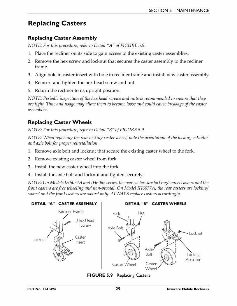
Replacing Casters
Replacing Caster AssemblyNOTE: For this procedure, refer to Detail “A” of FIGURE 5.9.
1. Place the recliner on its side to gain access to the existing caster assemblies.
2. Remove the hex screw and locknut that secures the caster assembly to the recliner frame.
3. Align hole in caster insert with hole in recliner frame and install new caster assembly.
4. Reinsert and tighten the hex head screw and nut.
5. Return the recliner to its upright position.
NOTE: Periodic inspection of the hex head screws and nuts is recommended to ensure that they are tight. Time and usage may allow them to become loose and could cause breakage of the caster assemblies.
Replacing Caster WheelsNOTE: For this procedure, refer to Detail “B” of FIGURE 5.9
NOTE: When replacing the rear locking caster wheel, note the orientation of the locking actuator and axle bolt for proper reinstallation.
1. Remove axle bolt and locknut that secure the existing caster wheel to the fork.
2. Remove existing caster wheel from fork.
3. Install the new caster wheel into the fork.
4. Install the axle bolt and locknut and tighten securely.
NOTE: On Models IH6074A and IH6065 series, the rear casters are locking/swivel casters and the front casters are free wheeling and non-pivotal. On Model IH6077A, the rear casters are locking/swivel and the front casters are swivel only. ALWAYS replace casters accordingly.
FIGURE 5.9 Replacing Casters
Locknut
Recliner Frame
Hex Head Screw
Caster Insert
Axle Bolt
Fork Nut
Caster Wheel
Axle Bolt Locking
Acruator
Locknut
Caster Wheel
DETAIL “A” - CASTER ASSEMBLY DETAIL “B” - CASTER WHEELS
Part No. 1141494 29 Invacare Mobile Recliners
SECTION 5—MAINTENANCE
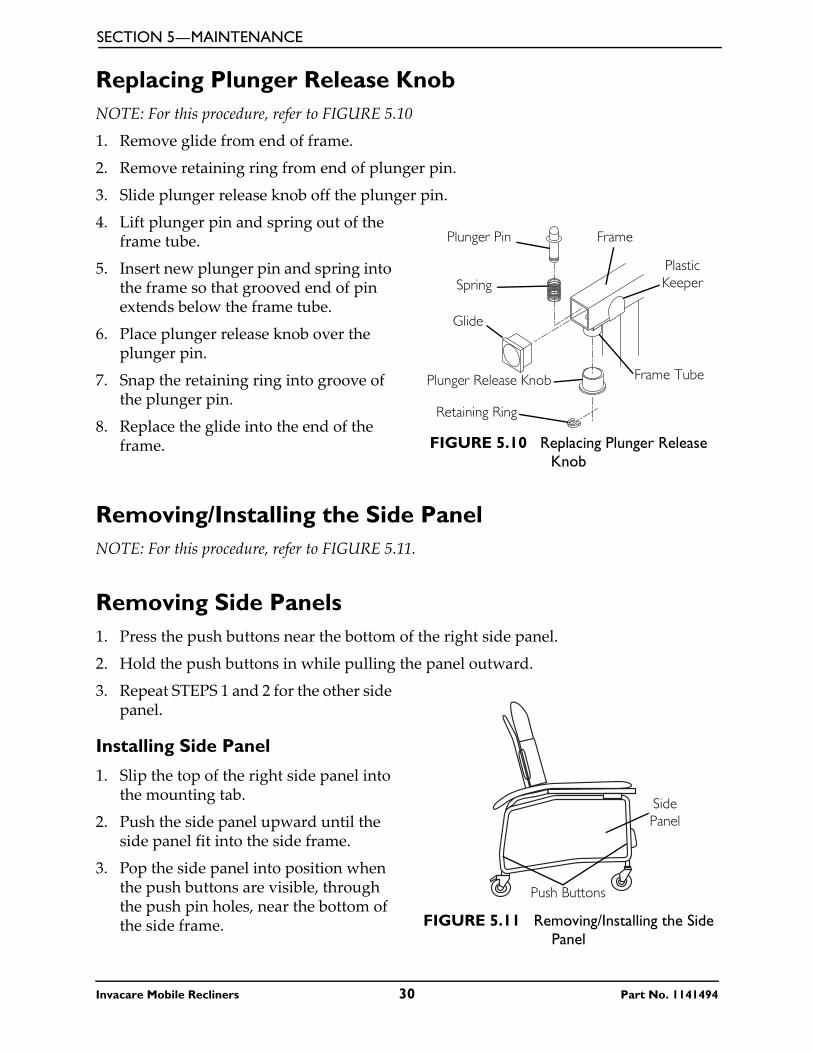
Replacing Plunger Release KnobNOTE: For this procedure, refer to FIGURE 5.10
1. Remove glide from end of frame.
2. Remove retaining ring from end of plunger pin.
3. Slide plunger release knob off the plunger pin.
4. Lift plunger pin and spring out of the frame tube.
5. Insert new plunger pin and spring into the frame so that grooved end of pin extends below the frame tube.
6. Place plunger release knob over the plunger pin.
7. Snap the retaining ring into groove of the plunger pin.
8. Replace the glide into the end of the frame. FIGURE 5.10 Replacing Plunger Release
Knob
Removing/Installing the Side PanelNOTE: For this procedure, refer to FIGURE 5.11.
Removing Side Panels1. Press the push buttons near the bottom of the right side panel.
2. Hold the push buttons in while pulling the panel outward.
3. Repeat STEPS 1 and 2 for the other side panel.
Installing Side Panel
1. Slip the top of the right side panel into the mounting tab.
2. Push the side panel upward until the side panel fit into the side frame.
3. Pop the side panel into position when the push buttons are visible, through the push pin holes, near the bottom of the side frame. FIGURE 5.11 Removing/Installing the Side
Panel
Plunger Pin
Spring
Glide
Plunger Release Knob
Retaining Ring
Frame
Frame Tube
Plastic Keeper
Push Buttons
Side Panel
Invacare Mobile Recliners 30 Part No. 1141494
SECTION 5—MAINTENANCE
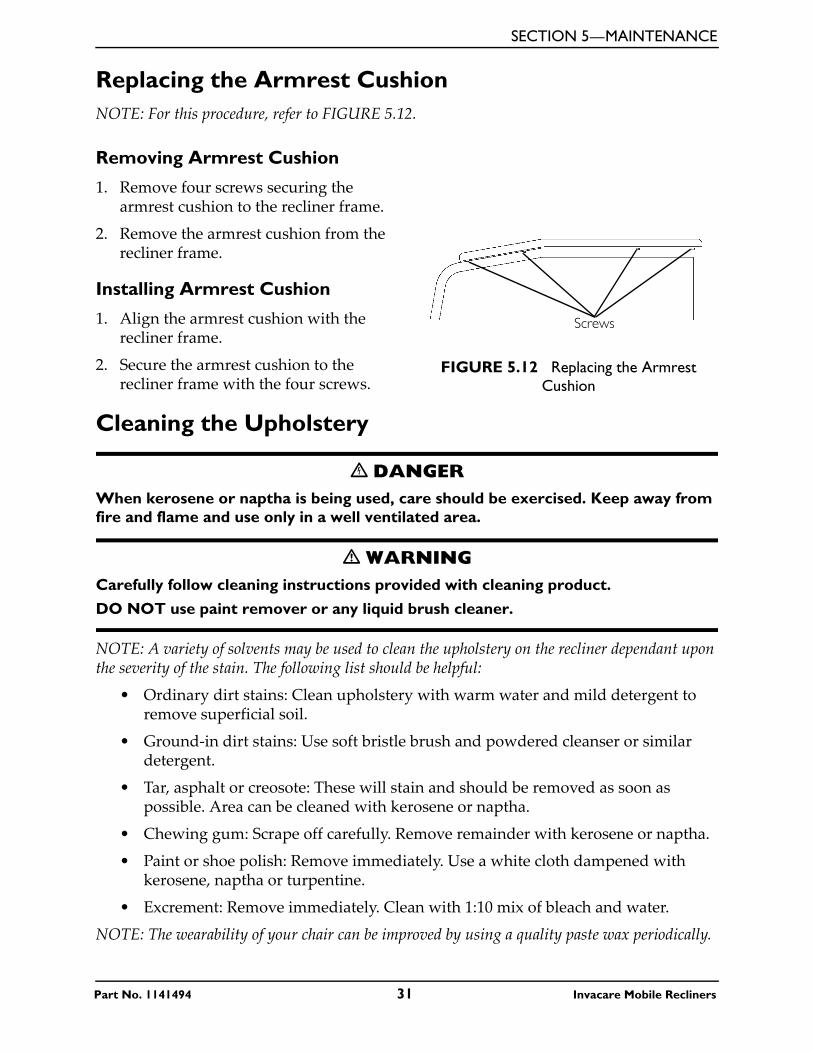
Replacing the Armrest CushionNOTE: For this procedure, refer to FIGURE 5.12.
Removing Armrest Cushion
1. Remove four screws securing the armrest cushion to the recliner frame.
2. Remove the armrest cushion from the recliner frame.
Installing Armrest Cushion
1. Align the armrest cushion with the recliner frame.
2. Secure the armrest cushion to the recliner frame with the four screws.
FIGURE 5.12 Replacing the Armrest Cushion
Cleaning the Upholstery
� DANGERWhen kerosene or naptha is being used, care should be exercised. Keep away from fire and flame and use only in a well ventilated area.
� WARNINGCarefully follow cleaning instructions provided with cleaning product.
DO NOT use paint remover or any liquid brush cleaner.
NOTE: A variety of solvents may be used to clean the upholstery on the recliner dependant upon the severity of the stain. The following list should be helpful:
• Ordinary dirt stains: Clean upholstery with warm water and mild detergent to remove superficial soil.
• Ground-in dirt stains: Use soft bristle brush and powdered cleanser or similar detergent.
• Tar, asphalt or creosote: These will stain and should be removed as soon as possible. Area can be cleaned with kerosene or naptha.
• Chewing gum: Scrape off carefully. Remove remainder with kerosene or naptha.
• Paint or shoe polish: Remove immediately. Use a white cloth dampened with kerosene, naptha or turpentine.
• Excrement: Remove immediately. Clean with 1:10 mix of bleach and water.
NOTE: The wearability of your chair can be improved by using a quality paste wax periodically.
Screws
Part No. 1141494 31 Invacare Mobile Recliners
LIMITED WARRANTYPLEASE NOTE: THE WARRANTY BELOW HAS BEEN DRAFTED TO COMPLY WITH FEDERAL LAW APPLICABLE TO PRODUCTS MANUFACTURED AFTER JULY 4, 1975.
This warranty is extended only to the original purchaser/user of our products.
This warranty gives you specific legal rights and you may also have other legal rights which vary from state to state.
Invacare warrants the products manufactured to be free from defects in materials and workmanship for a period of three years; and one year on the upholstery and Gas Spring Recline Cylinder from the date of purchase. If within such warranty period any such product shall be proven to be defective, such product shall be repaired or replaced, at Invacare’s option. This warranty does not include any labor or shipping charges incurred in replacement part installation or repair of any such product. Invacare’s sole obligation and your exclusive remedy under this warranty shall be limited to such repair and/or replacement.
For warranty service, please contact the dealer from whom you purchased your Invacare product. In the event you do not receive satisfactory warranty service, please write directly to Invacare at the address on the back cover, provide dealer’s name, address, date of purchase, indicate nature of the defect.
Invacare Corporation will issue a serialized return authorization. The defective unit or parts MUST be returned for warranty inspection using the serial number, when applicable as identification within 30 days of return authorization date. Do not return products to our factory without our prior consent. C.O.D. shipments will be refused; please prepay shipping charges.
LIMITATIONS AND EXCLUSIONS: THE FOREGOING WARRANTY SHALL NOT APPLY TO SERIAL NUMBERED PRODUCTS IF THE SERIAL NUMBER HAS BEEN REMOVED OR DEFACED, PRODUCTS SUBJECTED TO NEGLIGENCE, ACCIDENT, IMPROPER OPERATION, MAINTENANCE OR STORAGE, PRODUCTS MODIFIED WITHOUT INVACARE’S EXPRESS WRITTEN CONSENT (INCLUDING, BUT NOT LIMITED TO, MODIFICATION THROUGH THE USE OF UNAUTHORIZED PARTS OR ATTACHMENTS; PRODUCTS DAMAGED BY REASON OF REPAIRS MADE TO ANY COMPONENT WITHOUT THE SPECIFIC CONSENT OF INVACARE, OR TO A PRODUCT DAMAGED BY CIRCUMSTANCES BEYOND INVACARE’S CONTROL, AND SUCH EVALUATION WILL BE SOLELY DETERMINED BY INVACARE. THE WARRANTY SHALL NOT APPLY TO PROBLEMS ARISING FROM NORMAL WEAR OR FAILURE TO ADHERE TO THE INSTRUCTIONS IN THIS MANUAL.
THE FOREGOING WARRANTY IS EXCLUSIVE AND IN LIEU OF ALL OTHER EXPRESS WARRANTIES. IMPLIED WARRANTIES, IF ANY, INCLUDING THE IMPLIED WARRANTIES OF MERCHANTABILITY AND FITNESS FOR A PARTICULAR PURPOSE, SHALL NOT EXTEND BEYOND THE DURATION OF THE EXPRESSED WARRANTY PROVIDED HEREIN AND THE REMEDY FOR VIOLATIONS OF ANY IMPLIED WARRANTY SHALL BE LIMITED TO REPAIR OR REPLACEMENT OF THE DEFECTIVE PRODUCT PURSUANT TO THE TERMS CONTAINED HEREIN. INVACARE SHALL NOT BE LIABLE FOR ANY CONSEQUENTIAL OR INCIDENTAL DAMAGES WHATSOEVER.
SOME STATES DO NOT ALLOW EXCLUSION OR LIMITATION OF INCIDENTAL OR CONSEQUENTIAL DAMAGE, OR LIMITATION ON HOW LONG AN IMPLIED WARRANTY LASTS, SO THE ABOVE EXCLUSIONS AND LIMITATIONS MAY NOT APPLY TO YOU.
THIS WARRANTY SHALL BE EXTENDED TO COMPLY WITH STATE OR PROVINCIAL LAWS AND REQUIREMENTS.
Invacare Corporation www.invacare.com
USAOne Invacare WayElyria, Ohio USA44036-2125800-333-6900
Canada570 Matheson Blvd E Unit 8Mississauga OntarioL4Z 4G4 Canada800-668-5324
Invacare, Yes, You Can. and the Medallion Design are registered trademarks of Invacare Corporation.© 2006 Invacare Corporation
Part No. 1141494Rev A - 4/25/06
PRODUCT MADE IN CHINA