Introduction to VHDL - · PDF filedesign creation through synthesis. ... functions,...
49
Introduction to VHDL Introduction to VHDL The Five Design Units Modeling Styles Concurrent/Sequential Statements
-
Upload
nguyenkhuong -
Category
Documents
-
view
233 -
download
3
Transcript of Introduction to VHDL - · PDF filedesign creation through synthesis. ... functions,...

Introduction to VHDL
Introduction to VHDLThe Five Design UnitsModeling StylesConcurrent/Sequential Statements
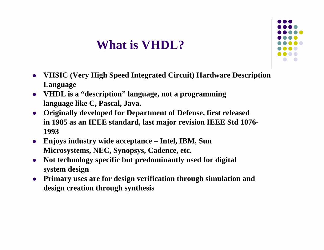
What is VHDL?
VHSIC (Very High Speed Integrated Circuit) Hardware DescriptionLanguageVHDL is a “description” language, not a programminglanguage like C, Pascal, Java.Originally developed for Department of Defense, first releasedin 1985 as an IEEE standard, last major revision IEEE Std 1076-1993Enjoys industry wide acceptance – Intel, IBM, SunMicrosystems, NEC, Synopsys, Cadence, etc.Not technology specific but predominantly used for digitalsystem designPrimary uses are for design verification through simulation anddesign creation through synthesis

VHDL Capabilities
Exchange medium between chip vendors and CAD tool usersSupports a wide range of abstraction levels, design, modeling stylesa. Behavioralb. Dataflowc. Structurald. Mixed
Clear separation of component’s architecture and interfaceSupports both synchronous and asynchronous timing modelsVarious delay constraints can be describedAllows defining new data typesSupports parameterized design using generics and attributesIs case insensitive and a strongly typed languageIEEE and ANSI Standard, therefore very portable

VHDL Primary Constructs
VHDL has five primary design constructs, also known as “Design Units”, used to describe logic1. Entity
The interface of a logic circuit is represented by entity2. Architecture
Architecture describes a particular implementation of anentity
3. ConfigurationConfiguration binds entities, architectures, andcomponent declarations
4. Package declarationPackage allows a convenient way to define and groupfunctions, procedures, types, components, etc.
5. Package bodyPackage body contains the implementation of thefunctionality exposed by package declaration
Design Unit : Entity
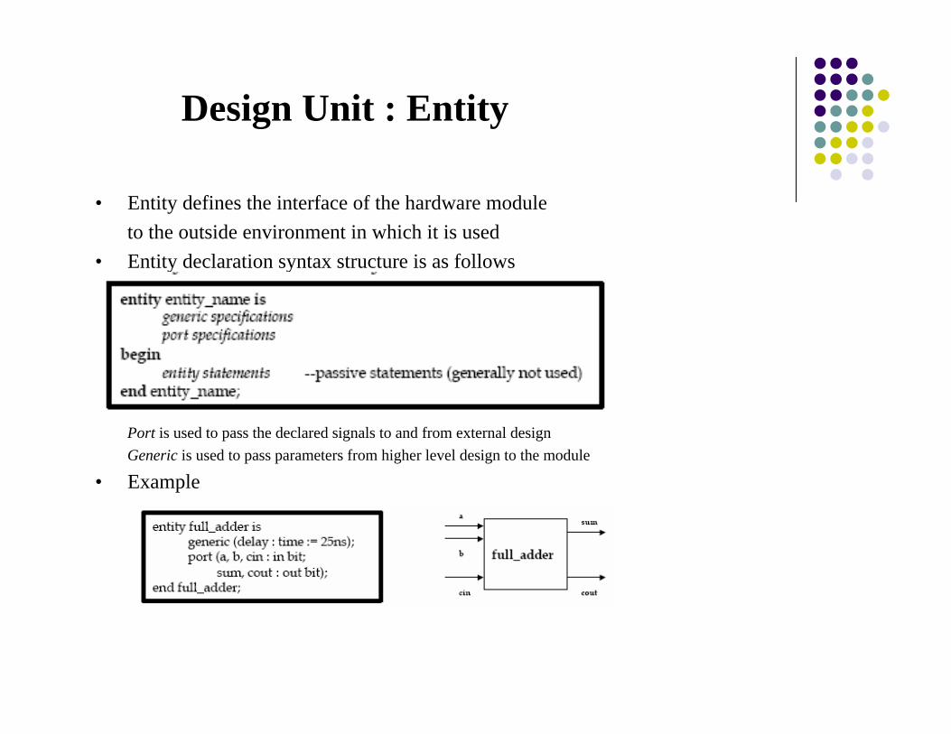
• Entity defines the interface of the hardware moduleto the outside environment in which it is used
• Entity declaration syntax structure is as follows
Port is used to pass the declared signals to and from external designGeneric is used to pass parameters from higher level design to the module
• Example

Lecture 2 6
Design Unit : Architecture
Architecture is the functionality description of thesystem declared by the entityIt can be a behavioral description or it can be astructural decomposition of the body in terms ofsimpler componentsAn architecture/entity pair defines a circuit. Multiplearchitectures can be defined for an entity
signal are any internal signals to be generated inside the modulecomponent is used for declaring any external entities to be used in this moduledescription can be either behavioral or structural

Lecture 2 7
Design Unit : Architecture
Examplearchitecture dataflow of full_adder issignal temp : bit;beginP1 : temp <= a xor b;P2 : sum <= cin xor temp;P3 : cout <= (a and b) or (a and cin) or (b and cin);end dataflow;
temp is a declared signal , a, b, cin, sum, cout are port signalsP1, P2, P3 are optional implicit process labels
Lecture 2 8
Design Unit : Configuration
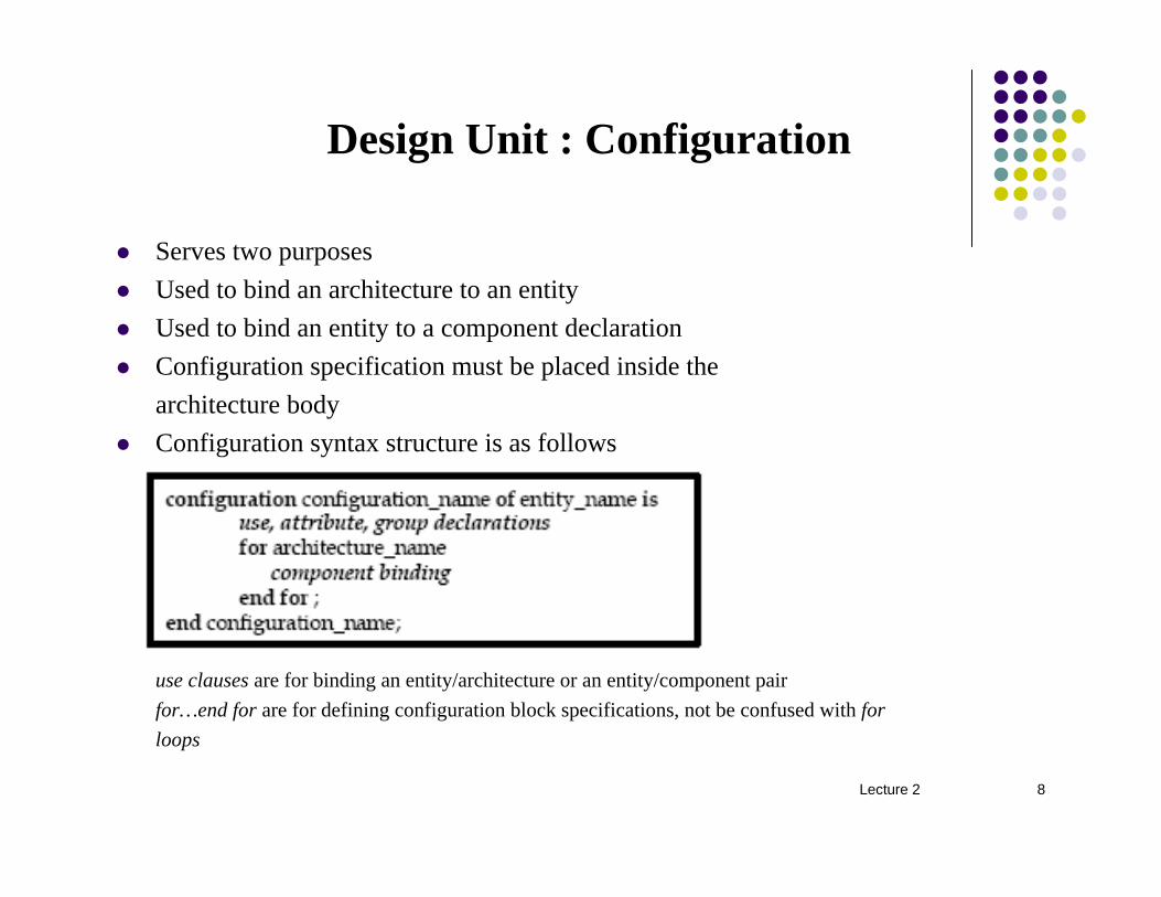
Serves two purposesUsed to bind an architecture to an entityUsed to bind an entity to a component declarationConfiguration specification must be placed inside thearchitecture bodyConfiguration syntax structure is as follows
use clauses are for binding an entity/architecture or an entity/component pairfor…end for are for defining configuration block specifications, not be confused with forloops

Lecture 2 9
Design Unit : Configuration
ExampleLibrary ieee;Use ieee.std_logic_1164.all;Entity counter isPort ( load, clear, clk : in std_logic;
data_in : in std_logic;data_out : out integer);
End counter;Architecture count_255 of counter isBegin
process(clk)Variable count : integer := 0;
Beginif clear = ‘1’ then
count := 0;else if load = ‘1’ thencount := data_in;
elseif (clk’event) and (clk = ‘1’) and
(clk’ last_value = ‘0’) thenif (count = 255) then
count := 0;else
Count := count + 1;End if;
end if;end if;Data_out <= count;End process;End count_255;

Lecture 2 10
Configuration small_count of counter isFor count_255End for;End small_count;
Configuration big_count of counter isFor count_64kEnd for;End big_count;
Architecture count_64k of counter isBeginProcess (clk)Variable count : integer := 0;BeginIf clear = ‘1’ then
Count := 0;Elsif load = ‘1’ then
Count := data_in;Else
If (clk’event) and (clk = ‘1’) and (clk’last_value = ‘0’) then
if (count = 65535)Count := 0;ElseCount := count +1;End if;
End if;End if;Data_out <= count;End process;End count_64k;

Lecture 2 11
Design Unit : Package Declaration
Packages are used to store commonly referenced types,functions, procedures, resolution functions, or componentsPackage declaration may only define the visible contents of thepackageExample
package my_pkg is -- Package Declaration
type bit3 is (`0',`1',`Z');
type bit_array is array (integer range <>) of bit3;
component or_gate
generic (or_blk_dly : time := 4 ns);
port (a0, b0 : in bit; c0 : out bit);
end component;
component and_gate
generic (and_blk_dly : time := 4 ns);
port (a1, b1 : in bit; c1: out bit);
end component;

Lecture 2 12
component xor_gategeneric (xor_blk_dly : time := 4 ns);port (a2, b2 : in bit; c2 : out bit);
end component;function citbv (p: integer) return bit_vector;end my_pkg;

Lecture 2 13
Design Unit : Package Body
The package body is essentially a listing of the implementationsfor functionality exposed by the package declarationExample
package body my_pkg is -- Package bodyfunction citbv (p: integer) return bit_vector is
Begincase p iswhen 0 => return "000";when 1 => return "001";when others => return "000";
end case;
Lecture 2 14
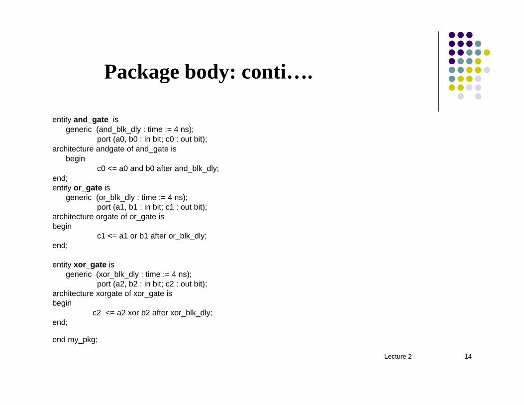
Package body: conti….
entity and_gate isgeneric (and_blk_dly : time := 4 ns);
port (a0, b0 : in bit; c0 : out bit);architecture andgate of and_gate is
beginc0 <= a0 and b0 after and_blk_dly;
end;entity or_gate is
generic (or_blk_dly : time := 4 ns);port (a1, b1 : in bit; c1 : out bit);
architecture orgate of or_gate isbegin
c1 <= a1 or b1 after or_blk_dly;end;
entity xor_gate isgeneric (xor_blk_dly : time := 4 ns);
port (a2, b2 : in bit; c2 : out bit);architecture xorgate of xor_gate isbegin
c2 <= a2 xor b2 after xor_blk_dly;end;
end my_pkg;

Lecture 2 15
VHDL Modeling Styles
Commonly used modeling styles in hardwaredescription are
Structural – Circuit is described as a network of interconnectedcomponentsBehavioral – Circuit is described as an i/o relationshipusing sequential statements inside a processDataflow – Circuit is described using concurrent statementsMixed - This style of modeling uses any combination ofother styles

Lecture 2 16
VHDL Modeling Styles : Structural
Focus is on how components are interconnected rather than theoperation of each fundamental component.Three features of a structural description1. Ability to define a list of components2. Definition of signals to interconnect these components3. Ability to distinguish between multiple copies of same
component using labelsExample

Lecture 2 17
VHDL Modeling Styles : Behavioral
This style describes a behavior in a “program-like” (procedural)manner, using the process constructs provided in VHDLMultiple process statements can be used to describe concurrencyNotice the following example uses sequential statements inside aprocess

Lecture 2 18
VHDL Modeling Styles : Dataflow
This style is convenient for illustrating asynchronousand concurrent events, where the delays representactual hardware component delaysIt is a realistic way of modeling hardwaredependencies and concurrenciesNotice the following example uses concurrentstatements
Lecture 2 19
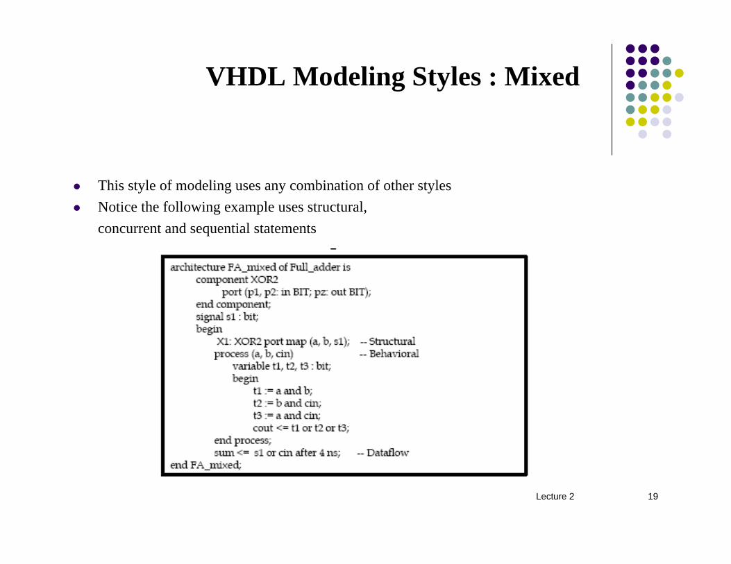
VHDL Modeling Styles : Mixed
This style of modeling uses any combination of other stylesNotice the following example uses structural,concurrent and sequential statements

Lecture 2 20
VHDL Statements : Sequential
Sequential Statements - These statements execute in a procedural fashion i.e. serially, inside a process
Process statementWait statementSequential signal assignmentVariable assignmentAssertion statementReport statementIf statementCase statementLoop statementNull statementNext statementExit statementFunction callProcedure call

Lecture 2 21
VHDL Statements : Concurrent
Concurrent Statements: These statements execute in a simultaneous fashion i.e. in parallel
BlockConcurrent signal assignmentComponent instantiationConcurrent procedure callConcurrent assertionGenerate
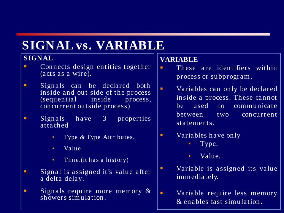
SIGNAL§ Connects design entities together
(acts as a wire).
§ Signals can be declared bothinside and out side of the process(sequential inside process,concurrentoutside process)
§ Signals have 3 propertiesattached
• Type & Type Attributes.
• Value.
• Time.(it has a history)
§ Signal is assigned it’s value aftera delta delay.
§ Signals require more memory &showers simulation.
VARIABLE§ These are identifiers within
process or subprogram.
§ Variables can only be declaredinside a process. These cannotbe used to communicatebetween two concurrentstatements.
§ Variables have only• Type.
• Value.
§ Variable is assigned its valueimmediately.
§ Variable require less memory& enables fast simulation.
SIGNAL vs. VARIABLEvs. VARIABLE

SIGNALprocessbeginwait for 10 ns;Sum1<=sum1+1;Sum2<=sum1+1;end process;
Time sum1 sum20 0 010 0 010+1delta 1 120 1 120+1 delta 2 230 2 230+1delta 3 3
VARIABLEprocessbeginwait for 10 ns;Sum1:=sum1+1;Sum2:=sum1+1;end process;
Time sum1 sum20 0 010 1 210+1delta 1 220 2 320+1 delta 2 330 3 430+1delta 3 4
SIGNAL vs. SIGNAL vs. VARIABLE EXAMPLEEXAMPLE

Filename=”ch5.doc”
5. 0 VHDL OPERATORS There are seven groups of predefined VHDL operators: 1. Binary logical operators: and or nand nor xor xnor 2. Relational operators: = /= < <= > >= 3. Shifts operators: sll srl sla sra rol ror 4. Adding operators: + - &(concatenation) 5. Unary sign operators: + - 6. Multiplying operators: * / mod rem 7. Miscellaneous operators: not abs ** The above classes are arranged in increasing priority when parentheses are not used. Example1: Priority of operators. Let A=”110”, B=”111”, C=”011000”, and D=”111011” (A & not B or C ror 2 and D) = “110010” ? the operators are applied in the following order: not, &, ror, or, and, = not B = ‘000” --bit-by-bit complement A & not B = “110000” --concatenation C ror 2 = “000110” --rotate right 2 places (A & not B) or (C ror 2) = “110110 --bit-by-bit or (A & not B or C ror 2) and D = “110010” --bit-by-bit and [(A & not B or C ror 2 and D) = “110010”]=TRUE --with parentheses the equality test is done last Example 2: Shift operators. Let A = “10010101” --are in IEEE.NUMERIC_BIT or in IEEE.NUMERIC_STD A sll 2 = “01010100” --shift left logical, filled with ‘0’ A srl 3 = “00010010” --shift right logical, filled with ‘0’ A sla 3 = “10101111” --shift left arithmetic, filled with right bit A sra 2 = “11100101” --shift right arithmetic, filled with left bit A rol 3 = “10101100” --rotate left by 3 A ror 5 = “10101100” --rotate right by 5 Example 3: arithmetic operators. If the left and right signed operands are of different lengths, the shortest operand will be sign-extended before performing an arithmetic operation. For unsigned operands, the shortest operand will be extended by filling in 0s on the left. signed: “01101” + “1011” = “01101” + “11011” = “01000” unsigned: “01101” + “1011” = “01101” + “01011” = “11000” TYPE SIGNED IS ARRAY(NATURAL RANGE <>) OF STD_LOGIC; TYPE UNSIGNED IS ARRAY(NATURAL RANGE <>) OF STD_LOGIC; When unsigned or signed addition is performed, the final carry is discarded, and overflow is ignored. If a carry is needed, an extra bit is appended to the leftmost bit.
1

Any overloaded binary operators perform binary operation with all argument of the same type. Vector arguments may be unequal in size, the smaller one is sign-extended to the same size as the larger argument before the operation is performed. For “+” operators, FUNCTION “+” (arg1, arg2 : STD_LOGIC) RETURN STD_LOGIC; FUNCTION “+” (arg1, arg2 : STD_ULOGIC_VECTOR) RETURN STD_ULOGIC_VECTOR; FUNCTION “+” (arg1, arg2 : STD_LOGIC_VECTOR) RETURN STD_LOGIC_VECTOR; FUNCTION “+” (arg1, arg2 : UNSIGNED) RETURN UNSIGNED; FUNCTION “+” (arg1, arg2 : SIGNED) RETURN SIGNED; CONSTANT A: unsigned(3 DOWNTO 0):= “1101”; CONSTANT B: signed(3 DOWNTO 0):=”1011”; VARIABLE SUMU: unsigned(4 DOWNTO 0); VARIABLE SUMS: signed(4 DOWNTO 0); VARIABLE OVERFLOW: boolean; SUMU:= ‘0’ & A + unsigned’(“0101”); --result is “10010” sum=2, carry=1 SUMS:=B(3) & B + signed(“1101”); --result is “”11000” sum =8, carry=1 The algorithm for adding two numbers in sign-2’s-complement representation gives an incorrect result when an overflow occurs. This arises because an overflow of the number bits always changes the sign of the result and gives an erroneous n-bit answer. Consider the following example. Two signed binary numbers, 35 and 40, are stored in two 7-bit registers. The maximum capacity of the register is (26–1)=63 and the minimum capacity is –26=-64. Since the sum of the numbers is 75, it exceeds the capacity of the register. This is true if the numbers are both positive or both negative. carries: 0 1 carries: 1 0 +35 0 100011 -35 1 011101 +40 0 101000 -40 1 011000 _____ ____________ _____ ____________ +75 1 001011 -75 0 110101 In either case, we see that the 7-bit result that should have been positive is negative, and vice versa. Obviously, the binary answer is incorrect and the algorithm for adding binary numbers represented in 2’s complement as stated previously fails to give correct results when an overflow occurs. Note that if the carry out of the sign-bit position is taken as the sign for the result, then the 8-bit answer so obtained will be correct. An overflow condition can be detected by observing the carry into the sign-bit position and the carry out of the sign-bit position. If these two carries are not equal, an overflow condition is produced. This is also detected if the sum in the sign-bit is different from the previous sum. 5.1 Two’s Complement Integer Addition It is assumed that the input vectors are in 2’s complement format. 1 LIBRARY IEEE; 2 USE IEEE.STD_LOGIC_1164ALL; 3 USE IEEE.STD_LOGIC_SIGNED.ALL; 4 5 ENTITY ovrflo_undrflo IS
2

Half Adder
vhdl code for halfadder using data flow style model.
⊕
library IEEE;
use IEEE.STD_LOGIC_1164.all;
entity ha is
port( a, b: in bit; sum,carry: out bit);
end entity;
architecture ha1 of ha is
begin
sum<= a xor b;
carry<= a and b;
end architecture;
vhdl code for halfadder using Behavioral style model.
library IEEE;
use IEEE.STD_LOGIC_1164.all;
entity ha is
port( a, b: in bit; sum,carry: out bit);
end entity;
architecture ha1 of ha is
begin
process (a,b)
begin
if (a ='0' and b='0') then
sum <= '0';
carry<='0';
elsif( a='0' and b='1')then
sum<= '1';
carry<='0';
elsif( a='1' and b='0')then
sum<= '1';
carry<='0';
elsif( a='1' and b='1')then
sum<= '0';

carry<='1';
end if;
end process;
end architecture;
vhdl code for halfadder using structural style model.
library IEEE;
use IEEE.STD_LOGIC_1164.all;
entity ha is
port(
a : in STD_LOGIC;
b : in STD_LOGIC;
sum : out STD_LOGIC;
carry : out STD_LOGIC
);
end ha;
architecture ha_stru of ha is
component xor2
port(l,m: in STD_LOGIC; n: out STD_LOGIC);
end component;
component and2
port(x,y: in STD_LOGIC; z: out STD_LOGIC);
end component;
for x1: xor2 use entity work.xor2(xor2);
for a1: and2 use entity work.and2(and2);
begin
x1: xor2 port map( a, b, sum);
a1: and2 port map(a,b,carry);
end ha_stru;
vhdl code for full-adder using data-flow model.
⊕ ⊕ Cin

library IEEE;
use IEEE.STD_LOGIC_1164.all;
entity fa1 is
port(
a : in STD_LOGIC;
b : in STD_LOGIC;
c : in STD_LOGIC;
sum : out STD_LOGIC;
carry : out STD_LOGIC
);
end fa1;
architecture fa_data1 of fa1 is
begin
sum <= a xor b xor c;
carry <= (a and b) or (c and (a xor b));
end fa_data1;
vhdl code for full-adder using Behavioral style model.
entity fa is
port( a, b: in bit;carry: inout bit; sum: out bit);
end entity;
architecture fa1 of fa is
begin
process (a,b,carry)
begin
if (a ='0' and b='0'and carry='0') then
sum <= '0';
carry<='0';
elsif(a ='0' and b='1'and carry='0') then
sum <= '1';
carry<='0';
elsif( a='1' and b='0'and carry = '0')then
sum <= '1';
carry <='0';
elsif( a='1' and b='1'and carry= '0')then
sum <= '0';
carry <='1';
elsif( a='0' and b='0'and carry= '1')then
sum <= '1';
carry <='0';
elsif( a='0' and b='1'and carry= '1')then
sum <= '0';
carry <='1';
elsif( a='1' and b='0'and carry= '1')then
sum <= '0';
carry <='1';
elsif( a='1' and b='1'and carry= '1')then
sum <= '1';
carry <='1';
end if;
end process;
end architecture;
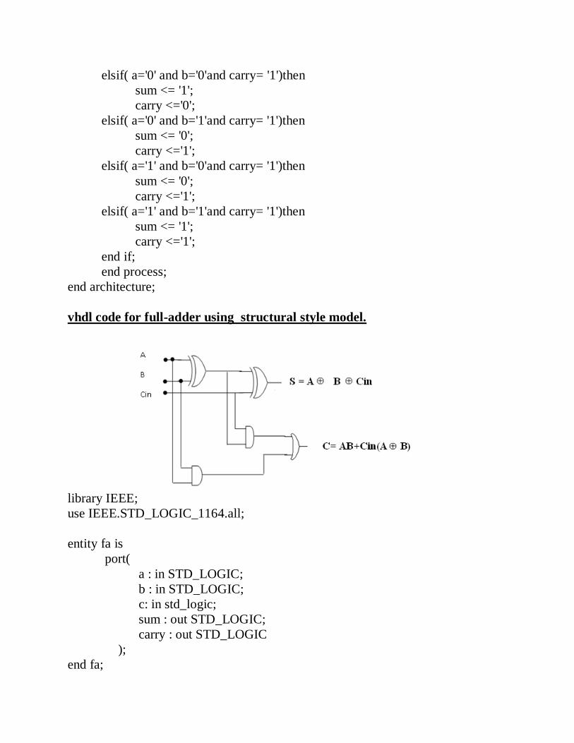
vhdl code for full-adder using structural style model.
library IEEE;
use IEEE.STD_LOGIC_1164.all;
entity fa is
port(
a : in STD_LOGIC;
b : in STD_LOGIC;
c: in std_logic;
sum : out STD_LOGIC;
carry : out STD_LOGIC
);
end fa;
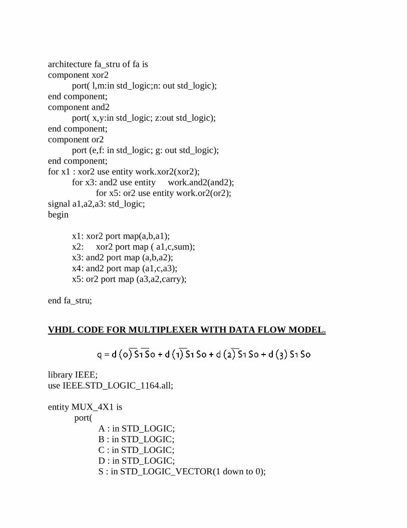
architecture fa_stru of fa is
component xor2
port( l,m:in std_logic;n: out std_logic);
end component;
component and2
port( x,y:in std_logic; z:out std_logic);
end component;
component or2
port (e,f: in std_logic; g: out std_logic);
end component;
for x1 : xor2 use entity work.xor2(xor2);
for x3: and2 use entity work.and2(and2);
for x5: or2 use entity work.or2(or2);
signal a1,a2,a3: std_logic;
begin
x1: xor2 port map(a,b,a1);
x2: xor2 port map ( a1,c,sum);
x3: and2 port map (a,b,a2);
x4: and2 port map (a1,c,a3);
x5: or2 port map (a3,a2,carry);
end fa_stru;
VHDL CODE FOR MULTIPLEXER WITH DATA FLOW MODEL.
library IEEE;
use IEEE.STD_LOGIC_1164.all;
entity MUX_4X1 is
port(
A : in STD_LOGIC;
B : in STD_LOGIC;
C : in STD_LOGIC;
D : in STD_LOGIC;
S : in STD_LOGIC_VECTOR(1 down to 0);

Y : out STD_LOGIC
);
end MUX_4X1;
architecture MUX_DATA of MUX_4X1 is
begin
Y<= A WHEN S(1)='0' AND S(0)='0' ELSE
B WHEN S(1)='0' AND S(0)='1' ELSE
C WHEN S(1)='1' AND S(0)='0' ELSE
D WHEN S(1)='1' AND S(0)='1' ;
end MUX_DATA;
VHDL CODE FOR MULTIPLEXER WITH BEHAVIORAL-MODEL
DESIGN
library IEEE;
use IEEE.STD_LOGIC_1164.all;
entity MUX_4X1 is
port(
A : in STD_LOGIC;
B : in STD_LOGIC;
C : in STD_LOGIC;
D : in STD_LOGIC;
S : in STD_LOGIC_VECTOR(1 down to 0);
Y : out STD_LOGIC
);
end MUX_4X1;
architecture MUX_BEH of MUX_4X1 is
begin
PROCESS(A,B,C,D,S)
BEGIN
CASE S IS
WHEN "00" => Y<= A;
WHEN "01" => Y<= B;
WHEN "10" => Y<= C;
WHEN "11" => Y<= D;
WHEN OTHERS => NULL;
END CASE;
END PROCESS;
end MUX_BEH;

VHDL CODE FOR MULTIPLEXER WITH structural style model
library IEEE;
use IEEE.STD_LOGIC_1164.all;
entity MUX4X1 is
port(
A : in STD_LOGIC;
B : in STD_LOGIC;
C : in STD_LOGIC;
D : in STD_LOGIC;
S0 : in STD_logic;
S1 : IN STd_logic;
Y : out STD_LOGIC
);
end MUX4X1;
architecture MUX_STRU of MUX4X1 is
COMPONENT AND3
PORT( L,M,O: IN STD_LOGIC; N: OUT STD_LOGIC);
END COmponent;
COMPONENT OR4
PORT( H,I,J,K: IN STD_LOGIC; H1: OUT STD_LOGIC);
END COmponent;
COMPONENT INV_1

PORT( E: IN STD_LOGIC; F: OUT STD_LOGIC);
END COmponent;
for v0:and3 use entity work.and3(and3);
for v4:or4 use entity work.or4(or4);
for u0:inv_1 use entity work.inv_1(inv_1);
SIGNAL S0BAR,S1BAR,W,X,G,Z: STD_LOGIC;
BEGIN
U0: INV_1 PORT MAP (S0,S0BAR);
U1: INV_1 PORT MAP (S1,S1BAR);
V0: AND3 PORT MAP (A,S1BAR,S0BAR,W);
V1: AND3 PORT MAP (B,S1BAR,S0 ,X);
V2: AND3 PORT MAP (C,S1 ,S0BAR,G);
V3: AND3 PORT MAP (D,S1 ,S0 ,Z);
V4: OR4 PORT MAP ( W,X,G,Z,Y);
end MUX_STRU;
SR FLIPFLOP
library ieee;
use ieee.std_logic_1164.all;
use ieee.std_logic_arith.all;
use ieee.std_logic_unsigned.all;
entity sr_ff is port
(S,R,clk:in std_logic;
x,y:out std_logic);
end sr_ff;
architecture behav of sr_ff is
begin
process(S,R,clk)
begin
if(clk='1' and S='0' and R='0')then x<='0';y<='0';
elsif(clk='1' and S='0' and R='1')then x<='0';y<='1';
elsif(clk='1' and S='1' and R='0')then x<='1';y<='0';
else x<='0';y<='0';
end if;
end process;
end behav;
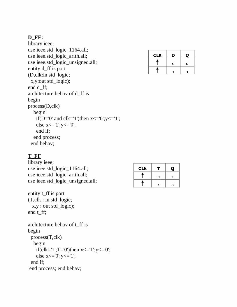
D_FF:
library ieee;
use ieee.std_logic_1164.all;
use ieee.std_logic_arith.all;
use ieee.std_logic_unsigned.all;
entity d_ff is port
(D,clk:in std_logic;
x,y:out std_logic);
end d_ff;
architecture behav of d_ff is
begin
process(D,clk)
begin
if(D='0' and clk='1')then x<='0';y<='1';
else x<='1';y<='0';
end if;
end process;
end behav;
T_FF
library ieee;
use ieee.std_logic_1164.all;
use ieee.std_logic_arith.all;
use ieee.std_logic_unsigned.all;
entity t_ff is port
(T,clk : in std_logic;
x,y : out std_logic);
end t_ff;
architecture behav of t_ff is
begin
process(T,clk)
begin
if(clk='1';T='0')then x<='1';y<='0';
else x<='0';y<='1';
end if;
end process; end behav;

JK_FF
library ieee;
use ieee.std_logic_1164.all;
use ieee.std_logic_arith.all;
use ieee.std_logic_unsigned.all;
entity jkflip is port
(clk,j,k:in std_logic;
q,qbar:inout std_logic);
end jkflip;
architecture behav of jkflip is
begin
process(clk,j,k)
begin
if clk='1' and clk'event then
if j='0' and k='0' then
q<=q;qbar<=qbar;
elsif j='0' and k='1' then
q<='0';qbar<='1';
elsif j='1' and k='0' then
q<='1';qbar<='0';
elsif j='1' and k='1' then
q<=qbar;qbar<=q;
end if;
end if;
end process;
13
TNE027 Digital Communication Electronics, Lecture 6
25
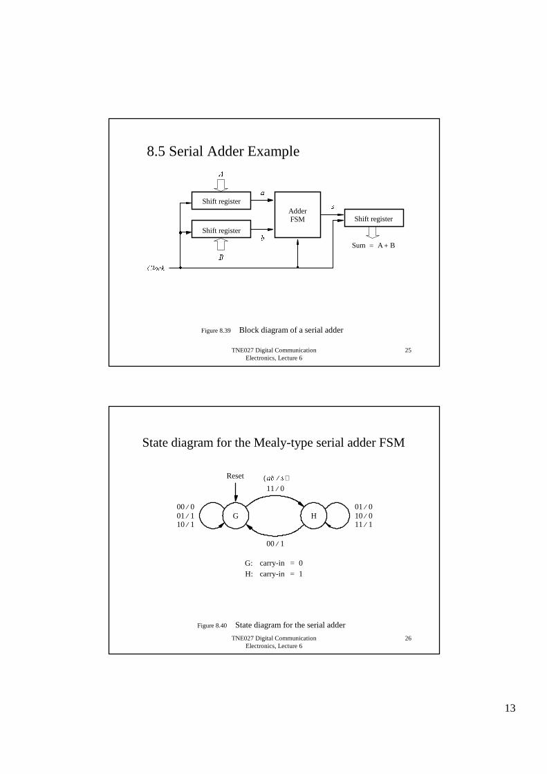
Figure 8.39 Block diagram of a serial adder
Sum A B + =
Shift register
Shift register
Adder FSM Shift register
%�
$�
D�
E�
V�
&ORFN�
8.5 Serial Adder Example
TNE027 Digital Communication Electronics, Lecture 6
26
Figure 8.40 State diagram for the serial adder
G
00 1 ⁄
11 1 ⁄ 10 0 ⁄ 01 0 ⁄
H 10 1 ⁄ 01 1 ⁄ 00 0 ⁄
carry-in 0 = carry-in 1 =
G:H:
Reset
11 0 ⁄ DE V�⁄ ( )
State diagram for the Mealy-type serial adder FSM

14
TNE027 Digital Communication Electronics, Lecture 6
27
Figure 8.43 Circuit for the adder FSM
Fulladder
D
E
V
D Q
Q
FDUU\�RXW
&ORFN
5HVHW
< \
TNE027 Digital Communication Electronics, Lecture 6
28
Figure 8.44 State diagram for the Moore-type serial adder FSM
H 1 V� 1 = ⁄
Reset
H 0 V� 0 = ⁄
011011
11
0110
G 1 V� 1 = ⁄
G 0 V� 0 = ⁄
0110 00
01
00
10
11
00
00
11
State diagram for the Moore-type serial adder FSM

15
TNE027 Digital Communication Electronics, Lecture 6
29
Figure 8.47 Circuit for the Moore-type serial adder FSM
Fulladder
D�
E�
D Q
Q &DUU\�RXW�
&ORFN�
5HVHW�
D Q
Q
V�
<�2
<�1 6XP�ELW�
\�2
\�1
TNE027 Digital Communication Electronics, Lecture 6
30
Figure 8.50a Synthesized serial adder
Adder FSM
&ORFN�
E
w L
E
w L
E�7 E�0
D�7 D�0
E
w L
E L
Q 3 Q 2 Q 1 Q 0
D 3 D 2 D 1 D 0
1 0 0 0
Counter
0 0
5HVHW�
6XP��� 6XP���
0 1
0 1
5XQ�
8-bit serial adder

16
TNE027 Digital Communication Electronics, Lecture 6
31
Figure 8.48a Code for a left-to-right shift register with an enable input
LIBRARY ieee ;USE ieee.std_logic_1164.all ;-- left-to-right shift register with parallel load and enableENTITY shiftrne IS
GENERIC ( N : INTEGER := 4 ) ;PORT ( R : IN STD_LOGIC_VECTOR(N-1 DOWNTO 0) ;
L, E, w : IN STD_LOGIC ;Clock : IN STD_LOGIC ;Q : BUFFER STD_LOGIC_VECTOR(N-1 DOWNTO 0) ) ;
END shiftrne ;ARCHITECTURE Behavior OF shiftrne ISBEGIN
PROCESSBEGIN
… con’t
TNE027 Digital Communication Electronics, Lecture 6
32
WAIT UNTIL Clock'EVENT AND Clock = '1' ;IF E = '1' THEN
IF L = '1' THENQ <= R ;
ELSEGenbits: FOR i IN 0 TO N-2 LOOP
Q(i) <= Q(i+1) ;END LOOP ;Q(N-1) <= w ;
END IF ;END IF ;
END PROCESS ;END Behavior ;
Figure 8.48b Code for a left-to-right shift register with an enable input (con’t)

17
TNE027 Digital Communication Electronics, Lecture 6
33
Figure 8.49a VHDL code for the serial adder
LIBRARY ieee ;USE ieee.std_logic_1164.all ;ENTITY serial IS
GENERIC ( length : INTEGER := 8 ) ;PORT ( Clock : IN STD_LOGIC ;
Reset : IN STD_LOGIC ;A, B : IN STD_LOGIC_VECTOR(length-1 DOWNTO 0) ;Sum : BUFFER STD_LOGIC_VECTOR(length-1 DOWNTO 0) );
END serial ;
ARCHITECTURE Behavior OF serial ISCOMPONENT shiftrne
GENERIC ( N : INTEGER := 4 ) ;PORT ( R : IN STD_LOGIC_VECTOR(N-1 DOWNTO 0) ;
L, E, w : IN STD_LOGIC ;Clock : IN STD_LOGIC ;Q : BUFFER STD_LOGIC_VECTOR(N-1 DOWNTO 0) ) ;
END COMPONENT ;SIGNAL QA, QB, Null_in : STD_LOGIC_VECTOR(length-1 DOWNTO 0) ;SIGNAL s, Low, High, Run : STD_LOGIC ;SIGNAL Count : INTEGER RANGE 0 TO length ;TYPE State_type IS (G, H) ;SIGNAL y : State_type ;
… con’t
TNE027 Digital Communication Electronics, Lecture 6
34
Figure 8.49b VHDL code for the serial adder (con’t)
BEGINLow <= ’0’ ; High <= ’1’ ;ShiftA: shiftrne GENERIC MAP (N => length)
PORT MAP ( A, Reset, High, Low, Clock, QA ) ;ShiftB: shiftrne GENERIC MAP (N => length)
PORT MAP ( B, Reset, High, Low, Clock, QB ) ;AdderFSM: PROCESS ( Reset, Clock )BEGIN
IF Reset = ’1’ THENy <= G ;
ELSIF Clock’EVENT AND Clock = ’1’ THENCASE y IS
WHEN G =>IF QA(0) = ’1’ AND QB(0) = ’1’ THEN y <= H ;ELSE y <= G ;END IF ;
WHEN H =>IF QA(0) = ’0’ AND QB(0) = ’0’ THEN y <= G ;ELSE y <= H ;END IF ;
END CASE ;END IF ;
END PROCESS AdderFSM ;
… con’t
Serial adder

18
TNE027 Digital Communication Electronics, Lecture 6
35
Figure 8.49c VHDL code for the serial adder (con’t)
WITH y SELECTs <= QA(0) XOR QB(0) WHEN G,
NOT ( QA(0) XOR QB(0) ) WHEN H ;Null_in <= (OTHERS => ’0’) ;ShiftSum: shiftrne GENERIC MAP ( N => length )
PORT MAP ( Null_in, Reset, Run, s, Clock, Sum ) ;Stop: PROCESSBEGIN
WAIT UNTIL (Clock’EVENT AND Clock = ’1’) ;IF Reset = ’1’ THEN
Count <= length ;ELSIF Run = ’1’ THEN
Count <= Count -1 ;END IF ;
END PROCESS ;Run <= ’0’ WHEN Count = 0 ELSE ’1’ ; -- stops counter and ShiftSum
END Behavior ;
Down counter
TNE027 Digital Communication Electronics, Lecture 6
36
Serial/parallel multiplier using carry-save adders
FA D
D
&
FA D
D
&
D ...
An-2 A0
FA
D
&
An-1Bn-1 Bn-2 ...B0
shift
...
Multiplicant An-1 An-2 ...A0 Multiplier Bn-1 Bn-2 ...B0

∆Vt
20. Write the equation for hold time. The hold time is expressed as th = Cs [Vs(0)-V1] Ileak Where V1 is the minimum voltage that can be recognized as a logic 1. Vs(0) is the initial voltage on the capacitor.
UNIT-V
VHDL
1)Write the acronym for VHDL? VHDL is an acronym for VHSIC Hardware Description Language (VHSIC is an
acronym for Very High Speed Integrated Circuits). 2) What are the different types of modeling VHDL?
1) Structural modeling 2) Data flow modeling 3) behavioral modeling 4) Mixed type of modeling
3) What is packages and what is the use of these packages A package declaration is used to store a set of common declaration such as
components types procedures and functions these declaration can then be imported into others design units using a use caluse. 4) What is variable class ,give example for variable
An object of variable class can also hold a single value of a given type , However in this case different values can be assigned to a variable at different time. Ex:variable ss: integer; 5) Name two subprograms and give the difference between these two.
1) Function 2) procedure Only one output is possible in function.. Many outputs possible using procedure

6) What is subprogram Overloading If two or more subprogram to be executed in a same name. overloading of
subprogram should be performed. 7) write the VHDL coding for a sequential statement (d-flipflop )
entity dff is port(clk,d:in std_logic; q:out std_logic); end; architecture dff of dff is begin process(clk,d) begin if clk’ event and clk=’ 1’ then q<=d; end process; end;
8) What are the different kinds of The test bench? Stimulus only Full testbench Simulator specific Hybrid testbench Fast testbench
9) What is Moore FSM The output of a Moore finite state machine(FSM) depends only on the state and
not on its inputs. This type of behaviour can be modeled using a single process with the case statement that switches on the state value. 10) Write the testbench for and gate
entity testand2 is end entity architecture io of testand2 is signal a,b,c:std_logic; begin g1:entity work.and2(ex2) port map(a,b,c) a<=’ 0’ ,’ 1’ after 100 ns; b<=’ 0’ , ‘1’ after 150 ns; end;
11) Give the different arithmetic operators?
Operator symbol Operation performed Number of operands * Multiply Two

/ Divide Two + Add Two - Subtract Two % Modulus Two ** Power (exponent) Two
12). Give the different bitwise operators. Operator symbol Operation performed Number of operands
~ Bitwise negation One & Bitwise and Two | Bitwise or Two ^ Bitwise xor Two ^~ or ~^ Bitwise xnor Two ~& Bitwise nand Two ~| Bitwise nor Two
13. Differentiate a signal and variable?
SIGNAL VARIABLE
Represents circuit in interconnects(wires) Represents local information
Can be global(seen by entire code) Local(visible only inside the corresponding PROCESS,FUNCTION,or PROCEDURE)
Update is not immediate in sequential code(new value generally only available at the conclusion of the PROCESS,FUNCTION, or PROCEDURE
Updated immediately (new value can be used in the next line of code)
14. Explain ‘case’ statement in VHDL with an Example. The case statement selects one of the branches for execution based on the value of expression. The expression value must be of discrete type or of a one-dimensional array type. Case is the statement intended exclusively for sequential code(along with IF, LOOP and WAIT). The syntax is CASE identifier IS WHEN value =>assignments; WHEN value =>assignments; … END CASE; EXAMPLE entity dff is
port(clk, rst,d:in std_logic; q:out std_logic);
end dff; architecture behaviour of dff is begin process(clk,d) begin case rst is WHEN ‘1’=> q<=’0’; WHEN ‘0’=> if (clk’ event and clk=’ 1’) then q<=d; end if; WHEN OTHERS=>NULL; End case; end process; end behaviour;
15.. Explain ‘BLOCK’ statement in VHDL with an Example. A block statement is a concurrent statement. It can be used for three major purposes: i. To disable signal drivers by using guards. ii. To limit scope of declarations , including signal declarations. iii. To represent a portion of a design. The two kinds of block is
1. simple. 2. guarded.
The syntax of block statement is Block-label:block[(guard-expression)] is [block-header] [block-declarations] Begin Concurrent-statements End block[block-label]; Example: BG:block(guard-expression) Signal SIG:BIT; Begin SIG<=guarded waveform-elements; End block BG;
16. Explain ‘Process’ statement in VHDL with an Example. A process statement contains sequential statements that describe the functionality of a portion of an entity in sequential terms. It is characterized by the presence of IF , WAIT,CASE or LOOP and by a sensitivity list. The syntax is
[label:] PROCESS(sensitivity list) [VARIABLE name type[range] [:=intial_value;] ] Begin (sequential code) End PROCESS [label]; Example: Architecture behaviour of example is SIGNAl temp:bit; Begin Temp <=a NAND b; PROCESS(clk) Begin If(clk ‘event and clk-‘1’) then Q<=temp; End PROCESS; End example;
17. Explain ‘Generate’ statement in VHDL with an Example. GENERATE is a concurrent statement(along with operators and WHEN). It is equivalent to the sequential statement LOOP in the sense that it allows a section of code to be repeated a number of times, thus creating several instances of the same assignments. The syntax is Label:FOR identifier IN range GENERATE (concurrent assignments) End GENERATE; Example: SIGNAL x: bit_vector(7 downto 0); SIGNAL y: bit_vector(15 downto 0); SIGNAL z: bit_vector(7 downto 0); … G1:FOR I IN x’ RANGE GENERATE Z(i)<=x(i) and y(i+8); End GENERATE;
18. What is Test Bench? The test bench name comes from the analogy with a real hardware test bench, on which a device under test is stimulated with waveform generates and observed with probes. A VHDL test bench consists of an architecture body containing an instance of component to be tested and processes that generate stimuli on signals , terminals or quantities connected to component instance. 19. Give the behavioral model for JK flipflop.
entity JKFF is port(SR, RN, J, K,clk:in std_logic;

q:out std_logic); end JKFF; architecture behaviour of JKFF is begin process(clk, SN, Rn) begin
if RN=’0’ then q<=’0’; elsif SN=’0’ then q<=’1’; elsif clk=’0’ and clk ‘event then q<=(J and NOT q) or (NOT k and q); end if; end process; end JKFF;
20. Give the behavioral model for T flipflop. entity tff is port(clk,t:in std_logic; q:out std_logic); end tff; architecture behaviour of tff is begin process(clk,t) begin if clk’ event and clk=’ 1’ then q<=d; end process; end behaviour;
21. Give the data flow model for half adder and half subtractor. // half adder
Entity halfadder is port(a, b:in std_logic; sum, carry:out std_logic); end halfadder; architecture behaviour of halfadder is sum<= a XOR b; carry<=a AND b; end behaviour // half subtractor Entity halfsubtractor is port(a, b:in std_logic; diff, borrow:out std_logic);

end halfadder; architecture behaviour of halfadder is diff<= a XOR b; borrow<= (NOT) a AND b; end behaviour;
22. Give the dataflow model for full adder. // full adder
Entity fulladder is port(a, b, c:in std_logic; sum, carry:out std_logic); end fulladder; architecture behaviour of fulladder is sum<= (a XOR b) XOR c; carry<=(a AND b) OR (b AND c) OR (c AND a); end behaviour;
23. Give the dataflow model for full subtractor. // full subtractor
Entity fulladder is port(a, b, c:in std_logic; diff, borrow:out std_logic); end fullsubtractor; architecture behaviour of fullsubtractor is diff<= (a XOR b) XOR c; borrow<=(NOT a AND b) OR (b AND c) OR (c AND NOT a);
end behaviour
24. What is component instantiation? A component instantiation statement defines a subcomponent of the entity in which it appears. It associates the signal in the entity with the ports of that subcomponent. A format of a component instantiation statement is Component-label:component-name[port map(associaton-list)]; Example: -- component declaration: component NAND2 port(A,B: in std-logic; Z:out std_logic); End component; -- component instantiation: N1:NAND2 port map(s1,s2,s3);
25.. Differentiate sequential from concurrent signal assignment statements. Sequential signal assignment statements
concurrent signal assignment statements

signal assignment statements can also appear within the body of process statement called sequential signal assignment statements
signal assignment statements that appear outside of process are called concurrent signal assignment statements.
Not event triggered and are executed in sequence in relation to other sequential statement that appear within the process.
Event triggered i.e., they are executed whenever there is an event on a signal that appears in its expression.
*****ALL THE BEST*****
.