Introduction to Verilog (Combinational Logic)
27
6.111 Fall 2004 Lecture 4, Slide 1 Introduction to Introduction to Verilog Verilog (Combinational Logic) (Combinational Logic) Acknowledgements : Anantha Chandrakasan, Rex Min Verilog References: • Samir Palnitkar, Verilog HDL, Pearson Education (2nd edition). • Donald Thomas, Philip Moorby, The Verilog Hardware Description Language, Fifth Edition, Kluwer Academic Publishers. • J. Bhasker, Verilog HDL Synthesis (A Practical Primer), Star Galaxy Publishing
Transcript of Introduction to Verilog (Combinational Logic)
6.111 Fall 2004 Lecture 4, Slide 1
Introduction to Introduction to VerilogVerilog(Combinational Logic)(Combinational Logic)
Acknowledgements : Anantha Chandrakasan, Rex Min
Verilog References:• Samir Palnitkar, Verilog HDL, Pearson Education (2nd edition).• Donald Thomas, Philip Moorby, The Verilog Hardware Description Language, Fifth Edition, Kluwer Academic Publishers. • J. Bhasker, Verilog HDL Synthesis (A Practical Primer), Star Galaxy Publishing
6.111 Fall 2004 Lecture 4, Slide 2
Verilog
Synthesis and Synthesis and HDLsHDLs
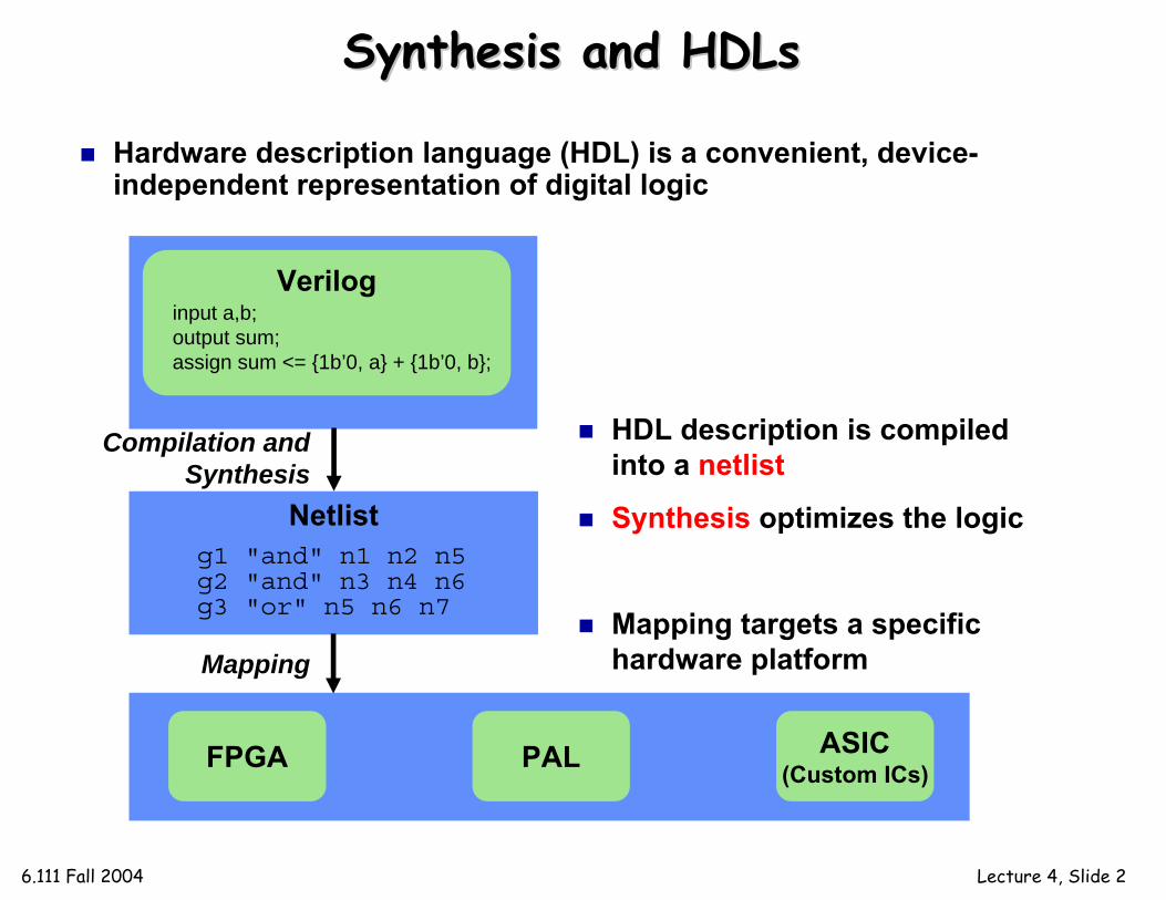
input a,b;output sum;assign sum <= {1b’0, a} + {1b’0, b};
FPGA PAL ASIC(Custom ICs)
Hardware description language (HDL) is a convenient, device-independent representation of digital logic
Netlistg1 "and" n1 n2 n5g2 "and" n3 n4 n6g3 "or" n5 n6 n7
HDL description is compiled into a netlist
Synthesis optimizes the logic
Mapping targets a specific hardware platform
Compilation and Synthesis
Mapping

6.111 Fall 2004 Lecture 4, Slide 3
The FPGA: A Conceptual ViewThe FPGA: A Conceptual View
An FPGA is like an electronic breadboard that is wired together by an automated synthesis toolBuilt-in components are called macros
sel
interconnect
D Q
LUTF(a,b,c,d)G(a,b,c,d)
abcd
RAMADR
R/WDATA
counter
+32
32
32SUM
(for everything else)

6.111 Fall 2004 Lecture 4, Slide 4
Synthesis and Mapping for Synthesis and Mapping for FPGAsFPGAs
Infer macros: choose the FPGA macros that efficiently implement various parts of the HDL code
Place-and-route: with area and/or speed in mind, choose the needed macros by location and route the interconnect
counter
...always @ (posedge clk)begin
count <= count + 1;end...
“This section of code looks like a counter. My FPGA has some of those...”
HDL Code Inferred Macro
M
M
M
M
M
M
M
M
M
M
M
M
M
M
M
M
M
M
M
M
M
M
M
M
M
M
M
M
M
M
M
M
M
M
M
“This design only uses 10% of the FPGA. Let’s use the macros in one corner to minimize the distance between blocks.”
6.111 Fall 2004 Lecture 4, Slide 5
VerilogVerilog: The Module: The Module
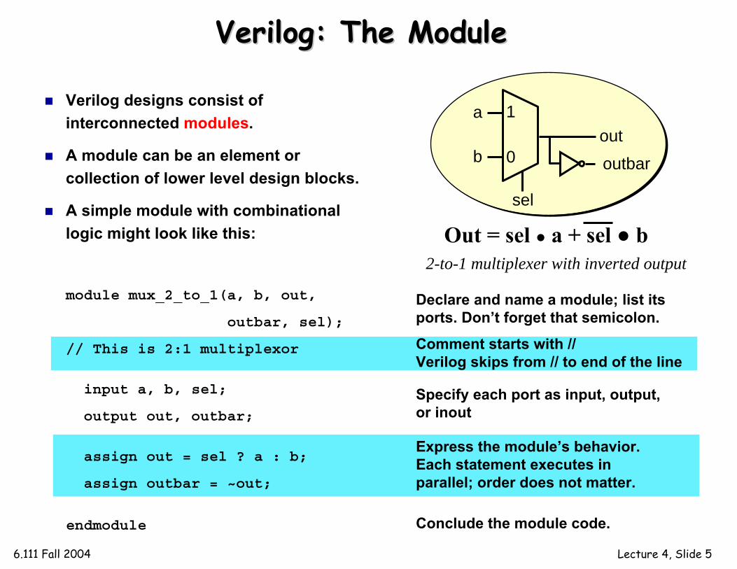
Verilog designs consist of interconnected modules.
A module can be an element or collection of lower level design blocks.
A simple module with combinational logic might look like this:
Declare and name a module; list its ports. Don’t forget that semicolon.
Specify each port as input, output, or inout
Express the module’s behavior. Each statement executes in parallel; order does not matter.
module mux_2_to_1(a, b, out,
outbar, sel);
// This is 2:1 multiplexor
input a, b, sel;
output out, outbar;
assign out = sel ? a : b;
assign outbar = ~out;
endmodule Conclude the module code.
2-to-1 multiplexer with inverted output
1
0
sel
outoutbar
a
b
Comment starts with // Verilog skips from // to end of the line
Out = sel ● a + sel ● b

6.111 Fall 2004 Lecture 4, Slide 6
Continuous (Dataflow) AssignmentContinuous (Dataflow) Assignment
Continuous assignments use the assign keywordA simple and natural way to represent combinational logicConceptually, the right-hand expression is continuously evaluated as a function of arbitrarily-changing inputs…just like dataflow The target of a continuous assignment is a net driven by combinational logicLeft side of the assignment must be a scalar or vector net or a concatenation of scalar and vector nets. It can’t be a scalar or vector register (discussed later). Right side can be register or netsDataflow operators are fairly low-level:
Conditional operator: (conditional_expression) ? (value-if-true) : (value-if-false);Boolean logic: ~, &, |, ^Arithmetic: +, -, *
Nested conditional operator (4:1 mux) assign out = s1 ? (s0 ? i3 : i2) : (s0? i1 : i0);
module mux_2_to_1(a, b, out, outbar, sel);
input a, b, sel;output out, outbar;
assign out = sel ? a : b;assign outbar = ~out;
endmodule
1
0
sel
outoutbar
a
b
6.111 Fall 2004 Lecture 4, Slide 7
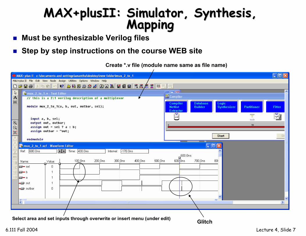
MAX+plusIIMAX+plusII: Simulator, Synthesis, : Simulator, Synthesis, MappingMapping
Must be synthesizable Verilog filesStep by step instructions on the course WEB site
Glitch
Create *.v file (module name same as file name)
Select area and set inputs through overwrite or insert menu (under edit)

6.111 Fall 2004 Lecture 4, Slide 8
Gate Level DescriptionGate Level Description
module muxgate (a, b, out, outbar, sel);input a, b, sel;output out, outbar;wire out1, out2, selb;
and a1 (out1, a, sel);not i1 (selb, sel);and a2 (out2, b , selb);or o1 (out, out1, out2);assign outbar = ~out;
endmodule
out
outbar
sel
a
b
Verilog supports basic logic gates as primitivesand, nand, or, nor, xor, xnor, not, buf
can be extended to multiple inputs: e.g., nand nand3in (out, in1, in2,in3);bufif1 and bufif0 are tri-state buffers
Net represents connections between hardware elements. Nets are declared with the keyword wire.
out1
out2selb

6.111 Fall 2004 Lecture 4, Slide 9
Procedural Assignment with Procedural Assignment with alwaysalways
module mux_2_to_1(a, b, out, outbar, sel);
input a, b, sel;output out, outbar;
reg out, outbar;
always @ (a or b or sel)
begin
if (sel) out = a;else out = b;
outbar = ~out;
end
endmodule
Procedural assignment allows an alternative, often higher-level, behavioral description of combinational logicTwo structured procedure statements: initial and always
Supports richer, C-like control structures such as if, for, while,case
Exactly the same as before.
Anything assigned in an alwaysblock must also be declared as type reg (next slide)
Conceptually, the always block runs once whenever a signal in the sensitivity list changes value
Statements within the alwaysblock are executed sequentially. Order matters!
Surround multiple statements in a single always block with begin/end.

6.111 Fall 2004 Lecture 4, Slide 10
VerilogVerilog RegistersRegisters
In digital design, registers represent memory elements (we will study these in the next few lectures)Digital registers need a clock to operate and update their state on certain phase or edgeRegisters in Verilog should not be confused with hardware registersIn Verilog, the term register (reg) simply means a variable that can hold a value Verilog registers don’t need a clock and don’t need to be driven like a net. Values of registers can be changed anytime in a simulation by assigning a new value to the register

6.111 Fall 2004 Lecture 4, Slide 11
MixMix--andand--Match AssignmentsMatch Assignments
Procedural and continuous assignments can (and often do) co-exist within a moduleProcedural assignments update the value of reg. The value will remain unchanged till another procedural assignment updates the variable. This is the main difference with continuous assignments in which the right hand expression is constantly placed on the left-side
module mux_2_to_1(a, b, out, outbar, sel);
input a, b, sel;output out, outbar;reg out;
always @ (a or b or sel) begin
if (sel) out = a;else out = b;
end
assign outbar = ~out;
endmodule
procedural description
continuous description
1
0
sel
outa
b outbar

6.111 Fall 2004 Lecture 4, Slide 12
The The casecase StatementStatement
case and if may be used interchangeably to implement conditional execution within always blocks
case is easier to read than a long string of if...else statements
module mux_2_to_1(a, b, out, outbar, sel);
input a, b, sel;output out, outbar;reg out;
always @ (a or b or sel) begin
if (sel) out = a;else out = b;
end
assign outbar = ~out;
endmodule
module mux_2_to_1(a, b, out, outbar, sel);
input a, b, sel;output out, outbar;reg out;
always @ (a or b or sel) begin
case (sel)1’b1: out = a;1’b0: out = b;
endcaseend
assign outbar = ~out;
endmodule
Note: Number specification notation: <size>’<base><number> (4’b1010 if a 4-bit binary value, 16’h6cda is a 16 bit hex number, and 8’d40 is an 8-bit decimal value)

6.111 Fall 2004 Lecture 4, Slide 13
The Power of The Power of VerilogVerilog: : nn--bit Signalsbit Signals
Multi-bit signals and buses are easy in Verilog.2-to-1 multiplexer with 8-bit operands:
1
0
sel
out
outbar
a
b
8
8
8
8
module mux_2_to_1(a, b, out, outbar, sel);
input[7:0] a, b;input sel;output[7:0] out, outbar;reg[7:0] out;
always @ (a or b or sel) begin
if (sel) out = a;else out = b;
end
assign outbar = ~out;
endmodule
assign {b[7:0],b[15:8]} = {a[15:8],a[7:0]};effects a byte swap
Concatenate signals using the { } operator
6.111 Fall 2004 Lecture 4, Slide 14
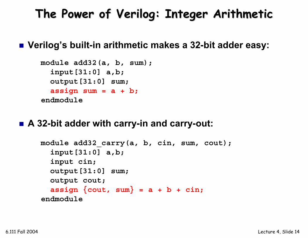
The Power of The Power of VerilogVerilog: Integer Arithmetic: Integer Arithmetic
Verilog’s built-in arithmetic makes a 32-bit adder easy:
A 32-bit adder with carry-in and carry-out:
module add32(a, b, sum);input[31:0] a,b;output[31:0] sum;assign sum = a + b;
endmodule
module add32_carry(a, b, cin, sum, cout);input[31:0] a,b; input cin;output[31:0] sum; output cout;assign {cout, sum} = a + b + cin;
endmodule

6.111 Fall 2004 Lecture 4, Slide 15
Dangers of Dangers of VerilogVerilog: Incomplete Specification: Incomplete Specification
module maybe_mux_3to1(a, b, c, sel, out);
input [1:0] sel;input a,b,c;output out;reg out;
always @(a or b or c or sel)begincase (sel)2'b00: out = a;2'b01: out = b;2'b10: out = c;
endcaseend
endmodule
Is this a 3-to-1 multiplexer?
Proposed Verilog Code:Goal:
00
sel
out01
10
a
b
c
2
3-to-1 MUX(‘11’ input is a don’t-care)

6.111 Fall 2004 Lecture 4, Slide 16
Latch memory “latches”old data when G=0 (we will discuss latches later)In practice, we almost never intend this
Incomplete Specification Infers LatchesIncomplete Specification Infers Latches
module maybe_mux_3to1(a, b, c, sel, out);
input [1:0] sel;input a,b,c;output out;reg out;
always @(a or b or c or sel)begin
case (sel)2'b00: out = a;2'b01: out = b;2'b10: out = c;
endcaseend
endmodule
if out is not assigned during any pass through
the always block, then the previous value must be
retained!
00
sel
out01
10
a
b
c
2
D Q
G
sel[1]sel[0]
Synthesized Result:
6.111 Fall 2004 Lecture 4, Slide 17
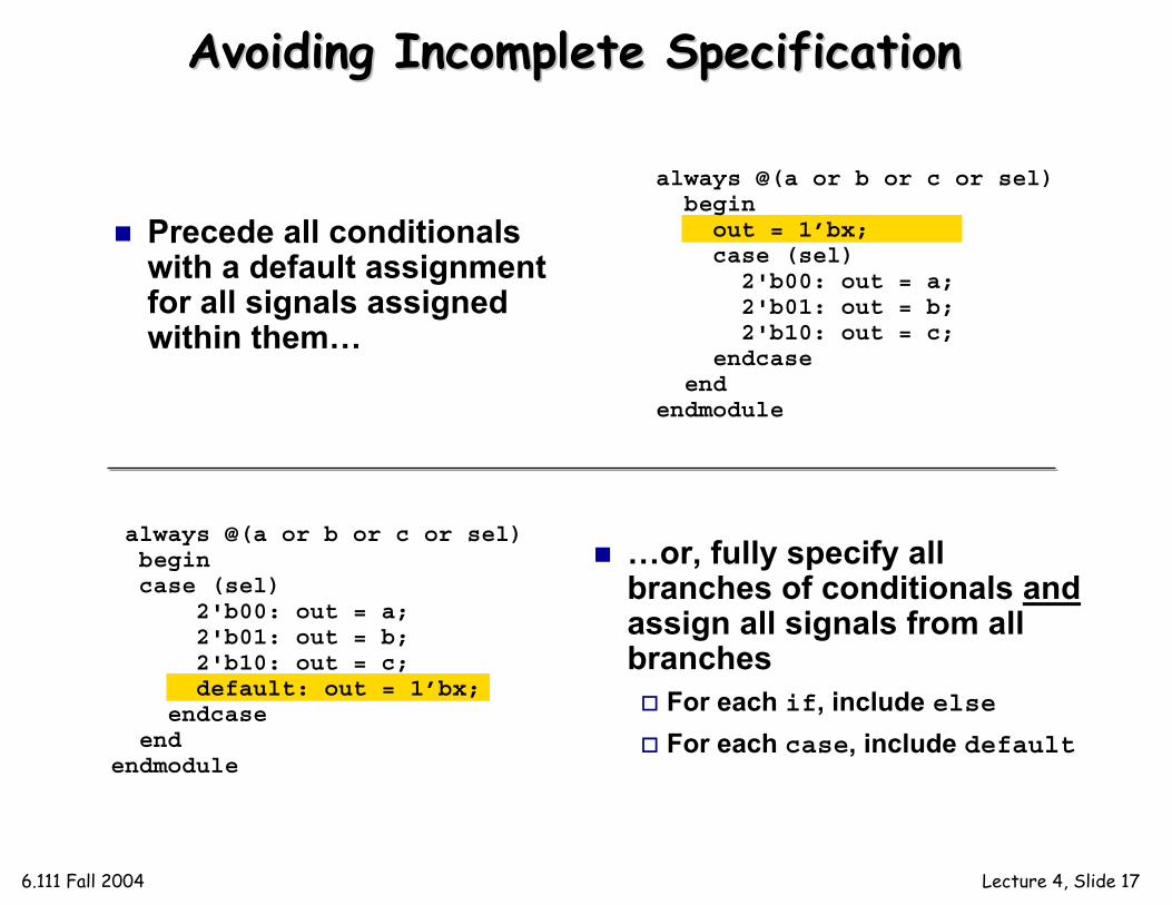
Avoiding Incomplete SpecificationAvoiding Incomplete Specification
Precede all conditionals with a default assignment for all signals assigned within them…
always @(a or b or c or sel)begin
out = 1’bx;case (sel)
2'b00: out = a;2'b01: out = b;2'b10: out = c;
endcaseend
endmodule
always @(a or b or c or sel)begincase (sel)
2'b00: out = a;2'b01: out = b;2'b10: out = c;default: out = 1’bx;
endcaseend
endmodule
…or, fully specify all branches of conditionals andassign all signals from all branches
For each if, include elseFor each case, include default
6.111 Fall 2004 Lecture 4, Slide 18
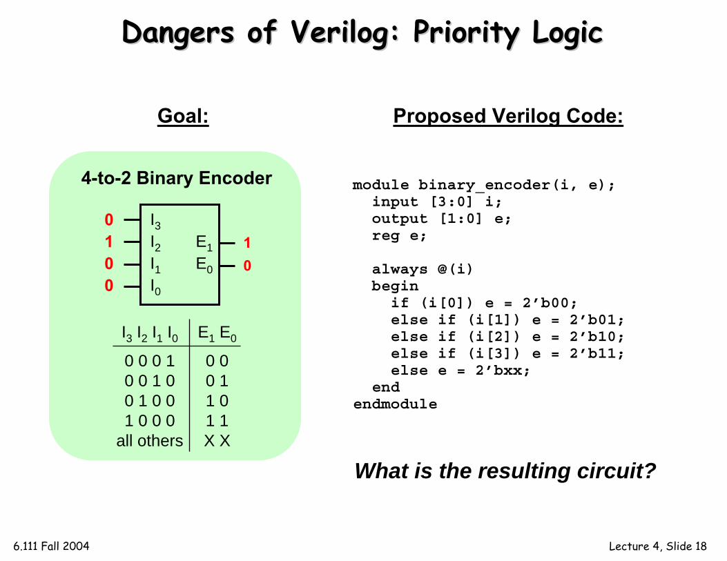
Dangers of Dangers of VerilogVerilog: Priority Logic: Priority Logic
module binary_encoder(i, e);input [3:0] i;output [1:0] e;reg e;
always @(i)begin
if (i[0]) e = 2’b00;else if (i[1]) e = 2’b01;else if (i[2]) e = 2’b10;else if (i[3]) e = 2’b11;else e = 2’bxx;
endendmodule
What is the resulting circuit?
Proposed Verilog Code:Goal:
I3I2I1I0
4-to-2 Binary Encoder
E1E0
10
0100
I3 I2 I1 I00 0 0 10 0 1 00 1 0 01 0 0 0
all others
E1 E0
0 00 11 01 1X X
6.111 Fall 2004 Lecture 4, Slide 19
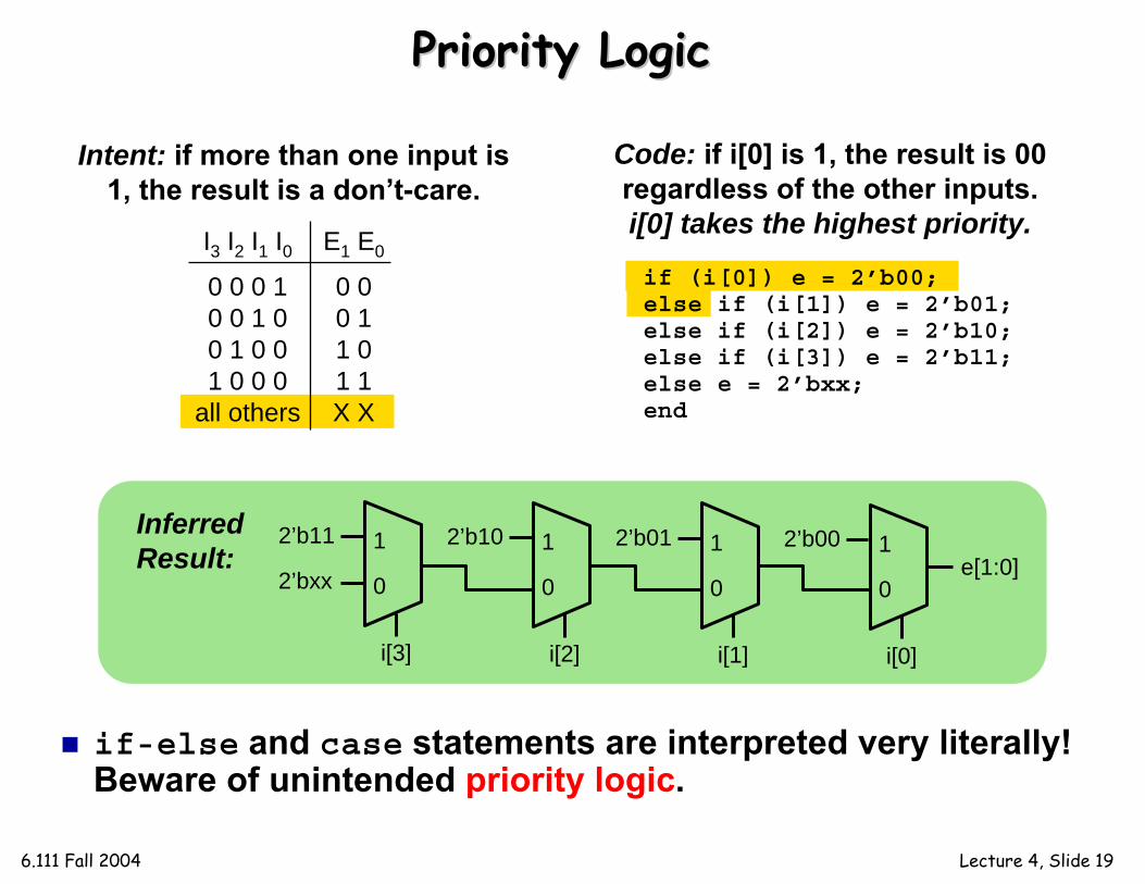
if (i[0]) e = 2’b00;else if (i[1]) e = 2’b01;else if (i[2]) e = 2’b10;else if (i[3]) e = 2’b11;else e = 2’bxx;end
Priority LogicPriority Logic
if-else and case statements are interpreted very literally! Beware of unintended priority logic.
Intent: if more than one input is 1, the result is a don’t-care.
I3 I2 I1 I00 0 0 10 0 1 00 1 0 01 0 0 0
all others
E1 E0
0 00 11 01 1X X
Code: if i[0] is 1, the result is 00 regardless of the other inputs. i[0] takes the highest priority.
1
i[0]
0
2’b001
i[1]
0
2’b011
i[2]
0
2’b101
i[3]
0
2’b11
2’bxx e[1:0]
Inferred Result:
6.111 Fall 2004 Lecture 4, Slide 20
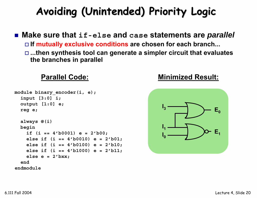
Avoiding (Unintended) Priority LogicAvoiding (Unintended) Priority Logic
Make sure that if-else and case statements are parallelIf mutually exclusive conditions are chosen for each branch......then synthesis tool can generate a simpler circuit that evaluates the branches in parallel
module binary_encoder(i, e);input [3:0] i;output [1:0] e;reg e;
always @(i)beginif (i == 4’b0001) e = 2’b00;else if (i == 4’b0010) e = 2’b01;else if (i == 4’b0100) e = 2’b10;else if (i == 4’b1000) e = 2’b11;else e = 2’bxx;
endendmodule
Minimized Result:Parallel Code:
I3
I1I0
E0
E1
6.111 Fall 2004 Lecture 4, Slide 21
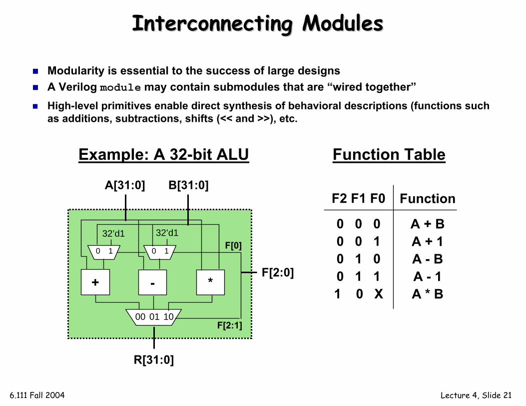
Interconnecting ModulesInterconnecting Modules
Modularity is essential to the success of large designsA Verilog module may contain submodules that are “wired together”High-level primitives enable direct synthesis of behavioral descriptions (functions such as additions, subtractions, shifts (<< and >>), etc.
A[31:0] B[31:0]
+ - *
0 1 0 1
32’d1 32’d1
00 01 10
R[31:0]
F[0]
F[2:1]
F[2:0]
Example: A 32-bit ALU
F2 F1 F0
0 0 00 0 10 1 00 1 11 0 X
Function
A + BA + 1A - BA - 1A * B
Function Table

6.111 Fall 2004 Lecture 4, Slide 22
Module DefinitionsModule Definitions
2-to-1 MUX 3-to-1 MUX
32-bit Adder 32-bit Subtracter 16-bit Multiplier
module mux32two(i0,i1,sel,out);input [31:0] i0,i1;input sel;output [31:0] out;
assign out = sel ? i1 : i0;
endmodule
module mux32three(i0,i1,i2,sel,out);input [31:0] i0,i1,i2;input [1:0] sel;output [31:0] out;reg [31:0] out;
always @ (i0 or i1 or i2 or sel)begin
case (sel)2’b00: out = i0;2’b01: out = i1;2’b10: out = i2;default: out = 32’bx;
endcaseendendmodule
module add32(i0,i1,sum);input [31:0] i0,i1;output [31:0] sum;
assign sum = i0 + i1;
endmodule
module sub32(i0,i1,diff);input [31:0] i0,i1;output [31:0] diff;
assign diff = i0 - i1;
endmodule
module mul16(i0,i1,prod);input [15:0] i0,i1;output [31:0] prod;
// this is a magnitude multiplier// signed arithmetic laterassign prod = i0 * i1;
endmodule
6.111 Fall 2004 Lecture 4, Slide 23
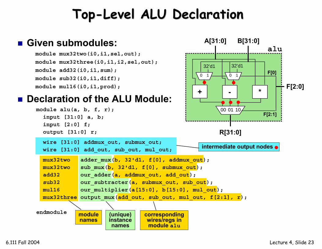
TopTop--Level ALU DeclarationLevel ALU Declaration
Given submodules:
Declaration of the ALU Module:
module mux32two(i0,i1,sel,out);
module mux32three(i0,i1,i2,sel,out);
module add32(i0,i1,sum);
module sub32(i0,i1,diff);
module mul16(i0,i1,prod);
module alu(a, b, f, r);
input [31:0] a, b;input [2:0] f;output [31:0] r;
wire [31:0] addmux_out, submux_out;wire [31:0] add_out, sub_out, mul_out;
mux32two adder_mux(b, 32'd1, f[0], addmux_out);mux32two sub_mux(b, 32'd1, f[0], submux_out);add32 our_adder(a, addmux_out, add_out);sub32 our_subtracter(a, submux_out, sub_out);
mul16 our_multiplier(a[15:0], b[15:0], mul_out);mux32three output_mux(add_out, sub_out, mul_out, f[2:1], r);
endmodule
A[31:0] B[31:0]
+ - *
0 1 0 1
32’d1 32’d1
00 01 10
R[31:0]
F[0]
F[2:1]
F[2:0]
modulenames
(unique)instancenames
corresponding wires/regs in module alu
intermediate output nodes
alu

6.111 Fall 2004 Lecture 4, Slide 24
SimulationSimulation
addition subtraction multiplier

6.111 Fall 2004 Lecture 4, Slide 25
More on Module InterconnectionMore on Module Interconnection
Explicit port naming allows port mappings in arbitrary order: better scaling for large, evolving designs
Built-in Verilog gate primitives may be instantiated as wellInstantiations may omit instance name and must be ordered:
buf(out1,out2,...,outN, in); and(in1,in2,...inN,out);
module mux32three(i0,i1,i2,sel,out);
mux32three output_mux(add_out, sub_out, mul_out, f[2:1], r);
mux32three output_mux(.sel(f[2:1]), .out(r), .i0(add_out),
.i1(sub_out), .i2(mul_out));
Given Submodule Declaration:
Module Instantiation with Ordered Ports:
Module Instantiation with Named Ports:
submodule’sport name
correspondingwire/reg in
outer module
6.111 Fall 2004 Lecture 4, Slide 26
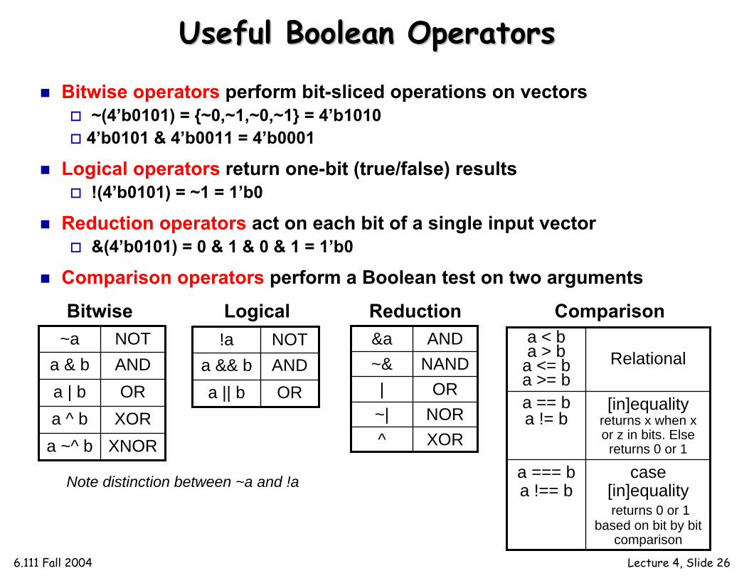
Useful Boolean OperatorsUseful Boolean Operators
Bitwise operators perform bit-sliced operations on vectors~(4’b0101) = {~0,~1,~0,~1} = 4’b10104’b0101 & 4’b0011 = 4’b0001
Logical operators return one-bit (true/false) results!(4’b0101) = ~1 = 1’b0
Reduction operators act on each bit of a single input vector&(4’b0101) = 0 & 1 & 0 & 1 = 1’b0
Comparison operators perform a Boolean test on two arguments
XNORa ~^ bXORa ^ bORa | b
ANDa & bNOT~a
Bitwise Logical
ORa || bANDa && bNOT!a
XOR^NOR~|OR|
NAND~&AND&a
Reduction
case [in]equalityreturns 0 or 1
based on bit by bit comparison
a === ba !== b
[in]equalityreturns x when x or z in bits. Else
returns 0 or 1
a == ba != b
Relationala < ba > b
a <= ba >= b
Comparison
Note distinction between ~a and !a
6.111 Fall 2004 Lecture 4, Slide 27
SummarySummary
Multiple levels of description: behavior, dataflow, logic and switch (not used in 6.111)Gate level is typically not used as it requires working out the interconnectsContinuous assignment using assign allows specifying dataflow structuresProcedural Assignment using always allows efficient behavioral description. Must carefully specify the sensitivity listIncomplete specification of case or if statements can result in non-combinational logicVerilog registers (reg) is not to be confused with a hardware memory elementModular design approach to manage complexity