Introduction to-telecommunication-rf
59
1 GSM900 DCS1800 troduction to Telecommunication Systems
-
Upload
terra-sacrifice -
Category
Technology
-
view
23 -
download
0
Transcript of Introduction to-telecommunication-rf

1
GSM900DCS1800
Introduction to Telecommunication Systems

2
•Describe the major components of the network and their interrelationships.•Describe how your voice is converted to electrical signals and transmitted over the network.
Objectives
Network Overview

3
• A system of interconnected elements• A system of various departments to
support these elements• Traffic is the flow of information or
messages throughout the network
Definition of a network:
4
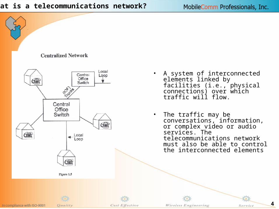
• A system of interconnected elements linked by facilities (i.e., physical connections) over which traffic will flow.
• The traffic may be conversations, information, or complex video or audio services. The telecommunications network must also be able to control the interconnected elements
What is a telecommunications network?
5
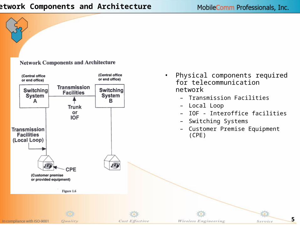
• Physical components required for telecommunication network
– Transmission Facilities– Local Loop– IOF - Interoffice facilities– Switching Systems– Customer Premise Equipment
(CPE)
Network Components and Architecture

6
•In its simplest form, a transmission facility is a communication between two end points. This communication path can also be referred to as:
•Channel•Circuit•Trunk
•For telephony purposes, the communication path (also known as network facilities) can be classified into two broad categories:
•Local Loop•Interoffice Facilities (IOF)/Trunk
Transmission Facilities

7
• The local loop:– is a circuit that connects a
customer to the telephone network.
– provides the customer with access to the switching system.
• The term "loop" is derived from the pair of wires that forms the electrical path between the customer and the central office.
• The local loop is also referred to as the subscriber loop.
• A simple local loop architecture is depicted in Figure
Transmission Facilities………..

8
•The primary functions of switching systems are to provide:
•Call setup and routing•Call supervision•Customer I.D. and phone numbers
•These are accomplished by interconnecting facilitiesSwitching systems located at the central office (CO) that are used to provide dial tone and ringing are referred to as end offices or local switches. These switches can also be interconnected with other switches. •Another type of switch, tandem, is used as a hub to connect switches and provide routing. (No dial tone is provided to the customer.)
Switching Systems

9
•Three components of any transmission system are the
•The transmitter•The receiver•The communication path
•In its simplest form, the CPE or customer premises equipment, is the transmitter and receiver. The media (twisted pair copper, coaxial cable, optical fiber, radio waves) that connects the CPE is the path.
Components for Transmission

10
•Many customers' telephones are connected to the central office by a pair of wires within a cable•Why two wires?
•Because your telephone is an electro-mechanical instrument, it requires a battery source and a ground source.
•The battery source is supplied from the central office equipment to your telephone set by a wire called the ring lead. The ground source is transmitted from the central office by a wire called the tip lead. Together, the tip and ring of the telephone set are commonly referred to as a cable pair.
Telephone Connection to the Central Office

11
Analog and Digital Transmission

12
•Describe a carrier system.•Describe the major differences between analog and digital signals.•Describe the analog to digital and digital to analog conversion process.•Compare and contrast Frequency Division Multiplexing and Time Division Multiplexing.
Objectives
Analog and Digital Transmission

13
•The telecommunications network can transmit a variety of information, in two basic forms, analog and digital. In this lesson we will examine both. This information may be transmitted over a circuit/channel or over a carrier system.•Where: A circuit/channel is a transmission path for a single type of transmission service (voice or data) and is generally referred to as the smallest subdivision of the network. A carrier, on the other hand, is a transmission path in which one or more channels of information are processed, converted to a suitable format and transported to the proper destination.
The two types of carrier systems we will be discussing in this lesson are:1. FDM (Frequency Division Multiplexing) -- analog2. TDM (Time Division Multiplexing) - digital
Introduction

14
• Multiplexing is the process of transmitting two or more individual signals over a common path. In effect, it increases the amount of information transmitted, while decreasing the requirement for the physical media (no longer a 1:1 ratio).
• Frequency Division Multiplexing• The first type of multiplexing was an analog multiplexing
technique. Frequency Division Multiplexing (FDM). In FDM, the bandwidth of the transmission path serves as the frame of reference for all of the information being transmitted. The total bandwidth is divided into subchannels consisting of smaller segments of the available bandwidth Each subchannel is capable of carrying a separate signal. Signals are transmitted simultaneously. Thus, with FDM each channel is:
• Assigned a different frequency • Separated into channels 4000 Hz. wide. • The different channels are then stacked and transported
over a common path. In other words, each channel occupies a portion of the total frequency bandwidth.
Multiplexing

15
• Digital Transmission, demanded by our customers, has continually increased since its introduction in 1962. This is due, in large part, to the fact that more of our customers require a high degree of accuracy in the information they are transmitting over our network. And with a digital transmission (as opposed to analog) system we are able to manage the quality of the signal by managing the previously discussed transmission impairments. Thus, digital systems: 1). are a better switching interface 2.) are easier to multiplex 3.)produce clearer signals
• Digital Signals A digital signal is a discrete signal. It is depicted as discontinuous -- Discretely variable (on/off) as opposed to an analog signal which is continuously variable (sine wave) A digital signal has the following characteristics:
1.) Holds a fixed value for a specific length of time2.) Has sharp, abrupt changes3.) A preset number of values allowed
Why Digital Transmission?

16
• Pulse Code Modulation (PCM) converts analog signals to a digital format (signal).
This process has four steps
The Pulse Code Modulation (PCM) Process

17
•Frequencies below 300 Hz and above 3400 Hz (Voice Frequency range) are filtered from the analog signal •The lower frequencies are filtered out to remove electrical noise induced from the power lines. •The upper frequencies are filtered out because they require additional bits and add to the cost of a digital transmission system. •The actual bandwidth of the filtered signal is 3100 Hz (3400 - 300). It is often referred to as 4 kHz.
Step One: Filtering

18
•The analog signal is sampled 8000 times per second. The rate at which the analog signal is sampled is related to the highest frequency present in the signal. This is based on the Nyquist sampling theorem. In his calculations, Nyquist used a voice frequency range of 4000 Hz (which represents the voice frequency range that contains "intelligent" speech). Thus, the standard became a sampling rate of 8000 Hz, or twice the bandwidth. The signal that is the result of the sampling process contains sufficient information to accurately represent the information contained in the original signal. The output of this sampling procedure is a Pulse Amplitude Modulated, or PAM, signal.
Step Two: Sampling

19
•In the third step of the A/D conversion process, we quantize the amplitude of the incoming samples to one of 255 amplitudes on a quantizing scale •Thus, in this step the sampled signal is matched to a segmented scale. The purpose of step three is to measure the amplitude (or height) of the PAM signal and assign a decimal value that defines the amplitude. Based on the quantizing scale, each sampled signal is assigned a number between 0 and +127 to define its amplitude.
Step Three and Four: Quantizing and Encoding
•In the fourth step of the A/D conversion process, the quantized samples are encoded into a digital bit stream (series of electrical pulses).

20
• Time division multiplexing (TDM) is a digital multiplexing technique. In TDM, a number of low rate channels are fed into a multiplexer (e.g., D Bank), which combines them into one high rate digital signal. Each of the 24 VF(voice frequency)/DS0 channels is assigned a specific time slot by the TDM(Time Division Multiplexer). Thus, TDM is a process by which several digital signals are combined onto a single path and sent sequentially. Relating this back to the PAM process: The analog signal is sampled 8000 times a second. There will be 8,000 eight-bit words transmitted per second. These words will be 1/8000 second (or 125 microseconds) apart.
Time division multiplexing (TDM)

21
•The digital hierarchy represents the standard rates by which digital communications are sent in North America. •The basic building block of the digital hierarchy is the DS0 rate at 64 Kbps. Remember that multiplying 8-bit words by the sampling rate of 8000 times/second produces the 64,000 bps rate. With Time Division Multiplexing, multiplexing by an additional 24 time slots and including 8000 framing bits for timing information produces the 1,544,000 bps or 1.544 Mbs. DS1 is considered the beginning of high capacity digital transmission rates.
Digital Hierarchy

22
Introduction to Switching
23
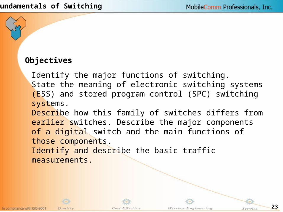
Identify the major functions of switching. State the meaning of electronic switching systems (ESS) and stored program control (SPC) switching systems. Describe how this family of switches differs from earlier switches. Describe the major components of a digital switch and the main functions of those components. Identify and describe the basic traffic measurements.
Objectives
Fundamentals of Switching

24
The purpose of a switch is to provide a path for the call. To process a call the switch performs three main functions:
1) Identifies the customer2) Sets up the communication path3) Supervises the call
Functions of a Switch

25
Initially customers were identified by the jack position they occupied on the switchboard. With the introduction of electromechanical switches, customers were as signed telephone numbers. (Also called line or station numbers.) The customer's cable pair is terminated and cross-connected to the office equipment at the main distributing frame. Office equipment terminated on the MDF represents a physical location in the switch and a specific telephone number. With the introduction of electronic switches, a telephone number is no longer wired to a specific component of the switch. The telephone number is now associated with a customer record which exists in the translations (or memory) of the switch.
Identify the Customers

26
Early in the processing of a call, the switch needs to determine what type of a call is being made. By analyzing either the first digit (is it a 0 or a 1?) or the first three digits (prefix), the switch will determine whether the call is intraswitch or inter-switch. If the call being processed is an intra-switch call, the path that the switch will allocate is called a line (i.e., "on the line side of the network"). If the call is an inter-switch call, the path that the switch will allocate is a trunk.
Set Up the Path
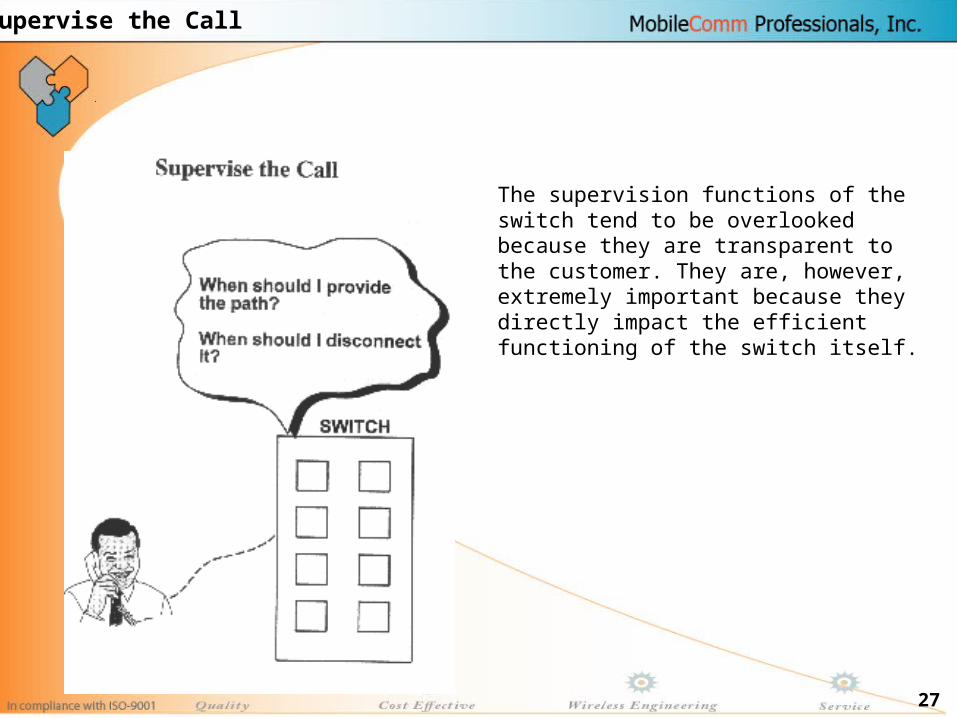
27
The supervision functions of the switch tend to be overlooked because they are transparent to the customer. They are, however, extremely important because they directly impact the efficient functioning of the switch itself.
Supervise the Call

28
Wireless Fundamentals

29
•Off Hook
•Dial Tone
•Dialing Digits
•RBT
•Conversation
•Ring
•Off Hook & Conversation
•Signaling•Traffic
SWITCH / EXCHANGE
BASIC Telephony

30
BSC
BTS BTS
Mobile Subscriber...
MSC
Wireless Telephony

31
• Till 1982 Cellular Systems were exclusively Analog Radio Technology.
• Advanced Mobile Phone Service (AMPS)
– U.S. standard on the 800 MHz Band
• Total Access Communication System (TACS)
– U.K. standard on 900 MHz band
• Nordic Mobile Telephone System (NMT)
– Scandinavian standard on the 450 & 900 MHz band
Different Standards Worldwide

32
Different Standards Worldwide

33
• End of 1980’s Analog Systems unable to meet continuing demands
– Severely confined spectrum allocations
– Interference in multipath fading environment
– Incompatibility among various analog systems
– Inability to substantially reduce the cost of mobile terminals and
infrastructure required
Analog Mobile Telephony

34
• Spectrum space - most limited and precious resource
• Solution - further multiplex traffic (time domain)
• Can be realized with Digital Techniques only
Digital Mobile Telephony

35
• A cellular system links Mobile subscribers to Public
Telephone System or to another Mobile subscribers.
• It removes the fixed wiring used in a traditional telephone installation.
• Mobile subscriber is able to move around, perhaps can travel
in a vehicle or on foot & still make & receive call.
Cellular Communication

36
• Mobility
• Flexibility
• Convergence
• Greater QOS
• Network Expansion
• Revenue/Profit
Advantage of Cellular Communication

37
Courtesy of Rich Howard
First Mobile Radio Telephone (1924)

38
• Advanced Mobile Phone Service (AMPS)– US trials 1978; deployed in Japan (’79) & US (’83)– 800 MHz band — two 20 MHz bands– TIA-553– Still widely used in US and many parts of the world
• Nordic Mobile Telephony (NMT)– Sweden, Norway, Demark & Finland– Launched 1981; now largely retired– 450 MHz; later at 900 MHz (NMT900)
• Total Access Communications System (TACS)– British design; similar to AMPS; deployed 1985– Some TACS-900 systems still in use in Europe
First Generation

39
• Digital systems• Leverage technology to increase capacity
– Speech compression; digital signal processing• Utilize/extend “Intelligent Network” concepts• Improve fraud prevention• Add new services• There are a wide diversity of 2G systems
– IS-54/ IS-136 North American TDMA; PDC (Japan)– iDEN – DECT and PHS– IS-95 CDMA (cdmaOne)– GSM
Second Generation — 2G

40
• Speech coded as digital bit stream– Compression plus error protection bits– Aggressive compression limits voice quality
• Time division multiple access (TDMA)– 3 calls per radio channel using repeating time slices
• Deployed 1993 (PDC 1994)– Development through 1980s; bakeoff 1987
• IS-54 / IS-136 standards in US TIA• ATT Wireless & Cingular use IS-136 today
– Plan to migrate to GSM and then to W-CDMA• PDC dominant cellular system in Japan today
– NTT DoCoMo has largest PDC network
D-AMPS/ TDMA & PDC

41
• Used by Nextel• Motorola proprietary system
– Time division multiple access technology– Based on GSM architecture
• 800 MHz private mobile radio (PMR) spectrum– Just below 800 MHz cellular band
• Special protocol supports fast “Push-to-Talk”– Digital replacement for old PMR services
• Nextel has highest APRU in US market due to “Direct Connect” push-to-talk service
iDEN

42
• Also based on time division multiple access • Digital European Cordless Telephony
– Focus on business use, i.e. wireless PBX– Very small cells; In building propagation issues– Wide bandwidth (32 kbps channels)– High-quality voice and/or ISDN data
• Personal Handiphone Service– Similar performance (32 kbps channels)– Deployed across Japanese cities (high pop. density)– 4 channel base station uses one ISDN BRI line– Base stations on top of phone booths– Legacy in Japan; new deployments in China today
DECT and PHS

43
• Code Division Multiple Access– All users share same frequency band– Discussed in detail later as CDMA is basis for 3G
• Qualcomm demo in 1989– Claimed improved capacity & simplified planning
• First deployment in Hong Kong late 1994• Major success in Korea (1M subs by 1996)• Used by Verizon and Sprint in US• Simplest 3G migration story today
North American CDMA (cdmaOne)

44
• TIA standard IS-95 (ANSI-95) in 1993• IS-95 deployed in the 800 MHz cellular band
– J-STD-08 variant deployed in 1900 MHz US “PCS” band
• Evolution fixes bugs and adds data– IS-95A provides data rates up to 14.4 kbps– IS-95B provides rates up to 64 kbps (2.5G)– Both A and B are compatible with J-STD-08
• All variants designed for TIA IS-41 core networks (ANSI 41)
cdmaOne — IS-95
45
• « Groupe Special Mobile », later changed to « Global System for Mobile »– Joint European effort beginning in 1982– Focus on seamless roaming across Europe
• Services launched 1991– Time division multiple access (8 users per 200KHz)– 900 MHz band; later extended to 1800MHz– Added 1900 MHz (US PCS bands)
• GSM is dominant world standard today– Well defined interfaces; many competitors– Network effect (Metcalfe’s law) took hold in late 1990s– Tri-band GSM phone can roam the world today
GSM

46
Multiple Access Technologies

47
30 KHz
30 KHz
30 KHz
30 KHz
30 KHz
30 KHz
30 KHz
30 KHzFre
qu
en
cyFDMA — Frequency Division Multiple Access
1G — Separate Frequencies

48
Fre
qu
en
cy
Time
200 KHz
200 KHz
200 KHz
200 KHz
One timeslot = 0.577 ms One TDMA frame = 8 timeslots
2G — TDMA Time Division Multiple Access

49
• Spread spectrum modulation– Originally developed for the military– Resists jamming and many kinds of interference– Coded modulation hidden from those w/o the code
• All users share same (large) block of spectrum– One for one frequency reuse– Soft handoffs possible
• Almost all accepted 3G radio standards are based on CDMA– CDMA2000, W-CDMA and TD-SCDMA
2G & 3G — CDMA Code Division Multiple Access

50
Courtesy of Petri Possi, UMTS World
Multi-Access Radio Techniques

51
• Universal global roaming• Multimedia (voice, data & video)• Increased data rates
– 384 kbps while moving– 2 Mbps when stationary at specific locations
• Increased capacity (more spectrally efficient)• IP architecture• Problems
– No killer application for wireless data as yet– Vendor-driven
3G Vision
52
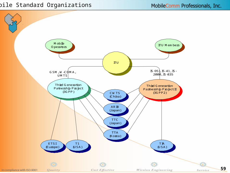
• ITU (International Telecommunication Union)– Radio standards and spectrum
• IMT-2000– ITU’s umbrella name for 3G which stands for International
Mobile Telecommunications 2000
• National and regional standards bodies are collaborating in 3G partnership projects– ARIB, TIA, TTA, TTC, CWTS. T1, ETSI - refer to reference
slides at the end for names and links
• 3G Partnership Projects (3GPP & 3GPP2)– Focused on evolution of access and core networks
International Standardization

53
Satellite
MacrocellMicrocell
UrbanIn-Building
Picocell
Global
Suburban
Basic TerminalPDA Terminal
Audio/Visual Terminal
IMT-2000 Vision

54
• IMT-SC* Single Carrier (UWC-136): EDGE– GSM evolution (TDMA); 200 KHz channels; sometimes called “2.75G”
• IMT-MC* Multi Carrier CDMA: CDMA2000– Evolution of IS-95 CDMA, i.e. cdmaOne
• IMT-DS* Direct Spread CDMA: W-CDMA– New from 3GPP; UTRAN FDD
• IMT-TC** Time Code CDMA– New from 3GPP; UTRAN TDD– New from China; TD-SCDMA
• IMT-FT** FDMA/TDMA (DECT legacy)
* Paired spectrum; ** Unpaired spectrum
IMT-2000 Radio Standards

55
• Evolution from original Qualcomm CDMA– Now known as cdmaOne or IS-95
• Better migration story from 2G to 3G– cdmaOne operators don’t need additional spectrum– 1xEVD0 promises higher data rates than UMTS, i.e. W-CDMA
• Better spectral efficiency than W-CDMA(?)– Arguable (and argued!)
• CDMA2000 core network less mature – cmdaOne interfaces were vendor-specific– Hopefully CDMA2000 vendors will comply w/ 3GPP2
CDMA2000 Pros and Cons
56
• Wideband CDMA– Standard for Universal Mobile Telephone Service (UMTS)
• Committed standard for Europe and likely migration path for other GSM operators– Leverages GSM’s dominant position
• Requires substantial new spectrum– 5 MHz each way (symmetric)
• Legally mandated in Europe and elsewhere• Sales of new spectrum completed in Europe
– At prices that now seem exorbitant
W-CDMA (UMTS) Pros and Cons
57
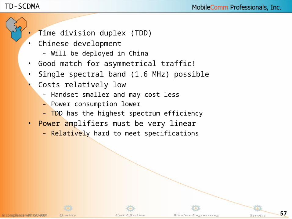
• Time division duplex (TDD)• Chinese development
– Will be deployed in China
• Good match for asymmetrical traffic!• Single spectral band (1.6 MHz) possible• Costs relatively low
– Handset smaller and may cost less– Power consumption lower– TDD has the highest spectrum efficiency
• Power amplifiers must be very linear– Relatively hard to meet specifications
TD-SCDMA

58
CDMA
GSM
TDMA
PHS (IP-Based)
64 Kbps
GPRS
115 Kbps
CDMA 1xRTT
144 Kbps
EDGE
384 Kbps
cdma20001X-EV-DV
Over 2.4 Mbps
W-CDMA (UMTS)
Up to 2 Mbps
2G2.5G
2.75G 3G
1992 - 2000+2001+
2003+
1G
1984 - 1996+
2003 - 2004+
TACS
NMT
AMPS
GSM/GPRS
(Overlay) 115 Kbps
9.6 Kbps
9.6 Kbps
14.4 Kbps/ 64 Kbps
9.6 Kbps
PDC
Analog Voice
Digital Voice
Packet Data
IntermediateMultimedia
Multimedia
PHS
TD-SCDMA
2 Mbps?
9.6 Kbps
iDEN
(Overlay)
iDEN
Source: U.S. Bancorp Piper Jaffray
Migration To 3G
59
ARIB(Japan)
T1(USA)
ETSI(Europe)
TTA(Korea)
CWTS(China)
TTC(Japan)
TIA(USA)
Third GenerationPatnership Project
(3GPP)
Third GenerationPartnership Project II
(3GPP2)
ITU
MobileOperators
ITU Members
IS-95), IS-41, IS-2000, IS-835
GSM, W-CDMA,UMTS
Mobile Standard Organizations


![Introduction to telecommunication systems - Pure · -switching systems ... networks or into the upper levels (trunk network). ... Introduction to Telecommunication Systems ]99]](https://static.fdocuments.in/doc/165x107/5ad67e927f8b9a177c8e5e92/introduction-to-telecommunication-systems-pure-systems-networks-or-into-the.jpg)