Introduction to Synergy
41
1 Chapter 1 Introduction to SynergyChapter1: Aim To learn the many features of the Autodesk Moldflow Synergy user interface. Why do it Autodesk Moldflow Synergy is the graphical user interface of Autodesk Moldflow Insight which provides you with a quick, easy-to-use method of preparing, running and post-processing an analysis of a particular part design. This chapter will introduce you to the various aspects of the user interface and show you how they can be used, as well as getting you up and running with a project and interacting with a model. Overview In this chapter, you will review and use the many interface features provided in Autodesk Moldflow Synergy, including: Menus Options Tabs Display window Panel, Project pane Working with projects Panel, Study tasks Entity selection Panel, Tools Entity properties Panel, Layers Model manipulation Context menus Wizards
Transcript of Introduction to Synergy

1
Chapter
1
Introduction to SynergyChapter 1:
Aim
To learn the many features of the Autodesk Moldflow Synergy user interface.
Why do it
Autodesk Moldflow Synergy is the graphical user interface of Autodesk Moldflow Insight which provides you with a quick, easy-to-use method of preparing, running and post-processing an analysis of a particular part design. This chapter will introduce you to the various aspects of the user interface and show you how they can be used, as well as getting you up and running with a project and interacting with a model.
Overview
In this chapter, you will review and use the many interface features provided in Autodesk Moldflow Synergy, including:
Menus Options
Tabs Display window
Panel, Project pane Working with projects
Panel, Study tasks Entity selection
Panel, Tools Entity properties
Panel, Layers Model manipulation
Context menus Wizards
Theory and Concepts - Introduction to Synergy
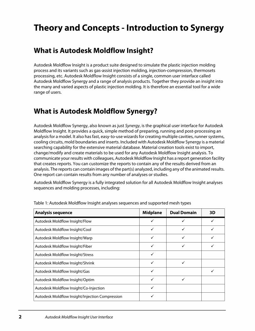
What is Autodesk Moldflow Insight?
Autodesk Moldflow Insight is a product suite designed to simulate the plastic injection molding process and its variants such as gas-assist injection molding, injection-compression, thermosets processing, etc. Autodesk Moldflow Insight consists of a single, common user interface called Autodesk Moldflow Synergy and a range of analysis products. Together they provide an insight into the many and varied aspects of plastic injection molding. It is therefore an essential tool for a wide range of users.
What is Autodesk Moldflow Synergy?
Autodesk Moldflow Synergy, also known as just Synergy, is the graphical user interface for Autodesk Moldflow Insight. It provides a quick, simple method of preparing, running and post-processing an analysis for a model. It also has fast, easy-to-use wizards for creating multiple cavities, runner systems, cooling circuits, mold boundaries and inserts. Included with Autodesk Moldflow Synergy is a material searching capability for the extensive material database. Material creation tools exist to import, change/modify and create materials to be used for any Autodesk Moldflow Insight analysis. To communicate your results with colleagues, Autodesk Moldflow Insight has a report generation facility that creates reports. You can customize the reports to contain any of the results derived from an analysis. The reports can contain images of the part(s) analyzed, including any of the animated results. One report can contain results from any number of analyses or studies.
Autodesk Moldflow Synergy is a fully integrated solution for all Autodesk Moldflow Insight analyses sequences and molding processes, including:
Table 1: Autodesk Moldflow Insight analyses sequences and supported mesh types
Analysis sequence Midplane Dual Domain 3D
Autodesk Moldflow Insight/Flow
Autodesk Moldflow Insight/Cool
Autodesk Moldflow Insight/Warp
Autodesk Moldflow Insight/Fiber
Autodesk Moldflow Insight/Stress
Autodesk Moldflow Insight/Shrink
Autodesk Moldflow Insight/Gas
Autodesk Moldflow Insight/Optim
Autodesk Moldflow Insight/Co-Injection
Autodesk Moldflow Insight/Injection Compression
2 Autodesk Moldflow Insight User Interface

Starting Autodesk Moldflow Synergy
Autodesk Moldflow Synergy can be started on a PC in two ways. During installation, there is a shortcut
created that looks like with the description Autodesk Moldflow Synergy with a version number. Synergy can also be started from the start menu. The path will be something like, Start > All Programs > Autodesk > Autodesk Moldflow Insight <version> > Autodesk Moldflow Synergy <version>.
The Autodesk Moldflow Synergy graphical user interface
Autodesk Moldflow Synergy, shown in Figure 1 is the environment used for pre-process, run and post-process an analysis for all Autodesk Moldflow Insight analyses sequences and molding processes.
Figure 1: Autodesk Moldflow Synergy window
Within Synergy, you can set up a sequence analysis (such as Cool + Fill + Pack + Warp), run the analysis, view the results and prepare a report. Each section is described in the following table.
Autodesk Moldflow Insight/Reactive Molding
Autodesk Moldflow Insight/Microchip Encapsulation
Autodesk Moldflow Insight/Underfill Encapsulation
Autodesk Moldflow Insight/Mucelltm
Table 1: Autodesk Moldflow Insight analyses sequences and supported mesh types (continued)
Analysis sequence Midplane Dual Domain 3D
Autodesk Moldflow Insight User Interface 3
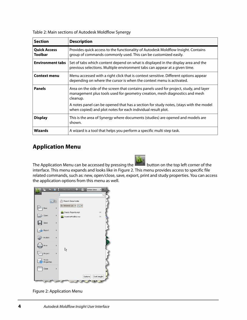
Application Menu
The Application Menu can be accessed by pressing the button on the top left corner of the interface. This menu expands and looks like in Figure 2. This menu provides access to specific file related commands, such as: new, open/close, save, export, print and study properties. You can access the application options from this menu as well.
Figure 2: Application Menu
Table 2: Main sections of Autodesk Moldflow Synergy
Section Description
Quick Access Toolbar
Provides quick access to the functionality of Autodesk Moldflow Insight. Contains group of commands commonly used. This can be customized easily.
Environment tabs Set of tabs which content depend on what is displayed in the display area and the previous selections. Multiple environment tabs can appear at a given time.
Context menu Menu accessed with a right click that is context sensitive. Different options appear depending on where the cursor is when the context menu is activated.
Panels Area on the side of the screen that contains panels used for project, study, and layer management plus tools used for geometry creation, mesh diagnostics and mesh cleanup.
A notes panel can be opened that has a section for study notes, (stays with the model when copied) and plot notes for each individual result plot.
Display This is the area of Synergy where documents (studies) are opened and models are shown.
Wizards A wizard is a tool that helps you perform a specific multi step task.
4 Autodesk Moldflow Insight User Interface

You can search a command from the Application menu. Just enter a word and the program will display the icon and path to the command or commands that contains the word you typed in the search box. You can select the command you need from the list to execute the action requested.
Figure 3: Search command
Quick Access ToolbarThe Quick Access Toolbar shown in Figure 4, located at the top of the Autodesk Moldflow Synergy window contains the most commonly used commands available in Synergy.
Figure 4: Quick Access Toolbar
The commands available in the menus depend on the stage of the simulation process you are currently in. Table 3 describes the function of each toolbar section.
Table 3: Autodesk Moldflow Synergy default Quick Access Toolbar and their functions
Toolbar Icon Function
New project Creates a new project, new study, new report or a new folder.
Open project Opens an existing project.
Import Imports a model.
Save Study Save, Save as and Save all studies here from this section. The last save command version you used is the icon shown.
Autodesk Moldflow Insight User Interface 5
Some options may be grayed out and unavailable for use. Which options are available depends on the object that is selected in Autodesk Moldflow Synergy.
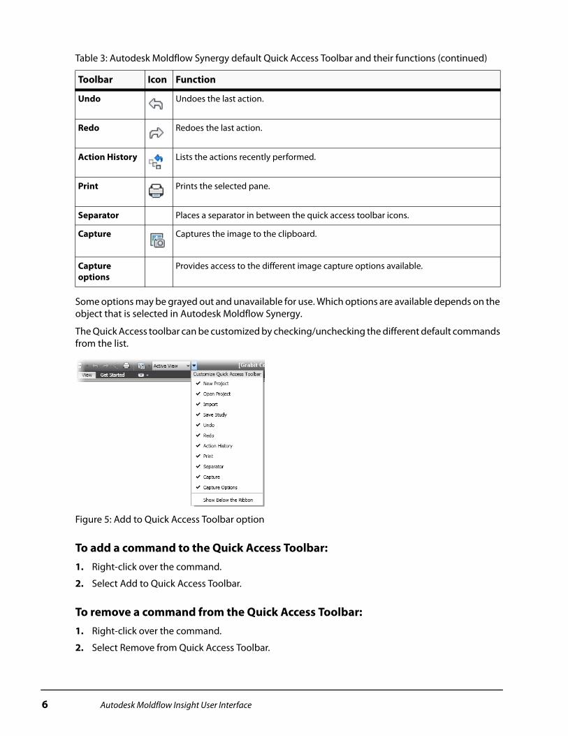
The Quick Access toolbar can be customized by checking/unchecking the different default commands from the list.
Figure 5: Add to Quick Access Toolbar option
To add a command to the Quick Access Toolbar:1. Right-click over the command.
2. Select Add to Quick Access Toolbar.
To remove a command from the Quick Access Toolbar:1. Right-click over the command.
2. Select Remove from Quick Access Toolbar.
Undo Undoes the last action.
Redo Redoes the last action.
Action History Lists the actions recently performed.
Print Prints the selected pane.
Separator Places a separator in between the quick access toolbar icons.
Capture Captures the image to the clipboard.
Capture options
Provides access to the different image capture options available.
Table 3: Autodesk Moldflow Synergy default Quick Access Toolbar and their functions (continued)
Toolbar Icon Function
6 Autodesk Moldflow Insight User Interface

Environment TabsThe Environment tabs change depending on what is currently shown in the display area and the previous selections. Figure 6 shows the Get Started environment tab that you see when opening Autodesk Moldflow Synergy for the first time.
Figure 6: Environment tab - Get Started tab
Multiple environment tabs can appear as a result of a selection. Once you are done with the tasks accessible through such environment tab just select finish/exit to return to the previous parent tab. Examples of child environment tabs are shown in the next images.
You can change the display of the environment tab at any time. Select any option from the pull-down menu located at the top of the tab as shown in Figure 7.
Figure 7: Environment tab display options selection
The next three images show the different options the home tab can be displayed as depending on the selection. All capabilities can be accessed through either display option.
Table 4 lists the different environment tabs available in the program along with its functions.
Autodesk Moldflow Insight User Interface 7

Context MenuThe context menu is a short menu that pops up after a right-mouse click. The context menu appears with different options, depending on what is highlighted or where the cursor is. Different context menus appear at the following locations, which they will be described in the next pages:
Table 4: Environment tabs available
Environment tabs
Function
Get Started Creating, opening, importing projects and models. Access to monitoring analysis running, access to tutorials, new features documentation and the community.
Home Importing, adding geometries and meshes. Setting the molding process and analysis sequence, selecting the material, configuring the process settings and all analysis prerequisites necessary for the selected process. Monitoring analysis running, reviewing results and creating reports.
Tools Creating, importing and editing databases for materials and other properties used in an analysis. The basic commands for the Application Programming Interface (API) are listed here as well.
View Displaying/hiding the various windows, tabs, etc. within Autodesk Moldflow Synergy. Functions for displaying layers and locking windows and results. Functions for manipulating the model and model display.
Sub tabs
The following environment tabs are opened from the Home tab.
Geometry Creating, duplicating or querying nodes, curves and regions, creating runners, cooling lines, inserts or mold boundary with the aid of Wizards, defining and activating a local coordinate system or modeling plane, and diagnosing surface problems. Tools for selecting entities and properties manipulation.
Mesh Creating, refining, diagnosing, and fixing meshes. Tools for selecting entities and properties manipulation.
Boundary Conditions
Adding or modifying boundary conditions to the model such as injection locations, prohibited gate notes, Dynamic Feed, coolant inlets, constraints and loads. Available boundary conditions depends on the molding process selected.
Results Setting display options for results, querying results and outputting results to a file. The preferences for the plots properties can be modified from this menu.
Reports Creating, editing and viewing reports based on one or more analyses. Notes, images and animations can be created from this tab as well.
Once sub environment tabs are opened they remain open until you click finish to close such tab. Sub tabs names are highlighted in colors so it is easy to identify them.
8 Autodesk Moldflow Insight User Interface
The project name, folder name, or study names in the Project pane.
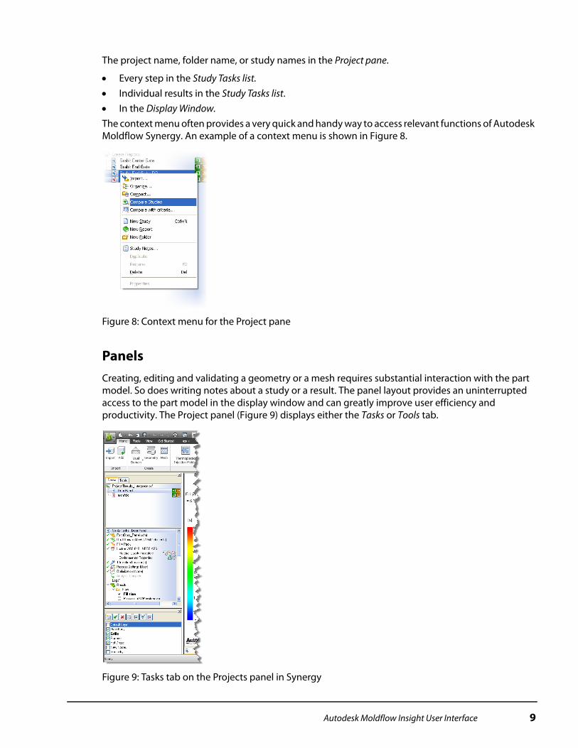
Every step in the Study Tasks list. Individual results in the Study Tasks list. In the Display Window.The context menu often provides a very quick and handy way to access relevant functions of Autodesk Moldflow Synergy. An example of a context menu is shown in Figure 8.
Figure 8: Context menu for the Project pane
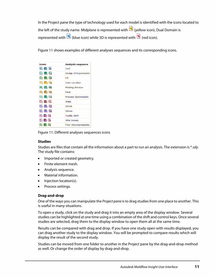
PanelsCreating, editing and validating a geometry or a mesh requires substantial interaction with the part model. So does writing notes about a study or a result. The panel layout provides an uninterrupted access to the part model in the display window and can greatly improve user efficiency and productivity. The Project panel (Figure 9) displays either the Tasks or Tools tab.
Figure 9: Tasks tab on the Projects panel in Synergy
Autodesk Moldflow Insight User Interface 9

Tasks tabsThe tasks tab is divided into two sections:
Project pane. Study tasks pane.A divider bar between the Project pane and the Study tasks pane is movable, so the relative sizes of the two panes can be changed at any time. The Tasks tab is shown in Figure 9.
Project paneThe Project pane is the top level of organization in Autodesk Moldflow Synergy. It contains a list of all the studies within a project. A project is equivalent to one “directory” on the hard disk, with a collection of Autodesk Moldflow Insight analysis files. Within the Project pane, studies can be organized into virtual “Folders” and any number of folders can be created to organize studies within one project.
For each study in the Project pane, you will see one or more icons to the right of the study name. These icons represent the types of analyses that can be run in Autodesk Moldflow Insight, and the status of a given analysis.
For example, the icon indicates the selected analysis is a filling analysis and has not yet been
completed because it is not filled. If an analysis is aborted, the icon similar to is shown. The red box with the “x” indicates an analysis was started but not finished and the solver has stopped. When
results are available for the study, the icon is filled in like this . Several icons can be grouped
together to form an analysis sequence such as , which indicates a Cool + Fill + Pack + Warp analysis (see Figure 10).
.
Figure 10: Project pane
The folders created in the Project pane are not “directories” on the hard disk. The only exception to this is report folders which are in fact created as subdirectories in the project directory.
10 Autodesk Moldflow Insight User Interface
In the Project pane the type of technology used for each model is identified with the icons located to
the left of the study name. Midplane is represented with (yellow icon), Dual Domain is
represented with (blue icon) while 3D is represented with (red icon).
Figure 11 shows examples of different analyses sequences and its corresponding icons.
Figure 11: Different analyses sequences icons
StudiesStudies are files that contain all the information about a part to run an analysis. The extension is *.sdy. The study file contains:
Imported or created geometry. Finite element mesh. Analysis sequence. Material information. Injection location(s). Process settings.
Drag-and-dropOne of the ways you can manipulate the Project pane is to drag studies from one place to another. This is useful in many situations.
To open a study, click on the study and drag it into an empty area of the display window. Several studies can be highlighted at one time using a combination of the shift and control keys. Once several studies are selected, drag them to the display window to open them all at the same time.
Results can be compared with drag and drop. If you have one study open with results displayed, you can drag another study to the display window. You will be prompted to compare results which will display the result of the second study.
Studies can be moved from one folder to another in the Project pane by the drag-and-drop method as well. Or change the order of display by drag-and-drop.
Autodesk Moldflow Insight User Interface 11

Compare studiesWhen two or more studies are highlighted in the Project pane and you click the right mouse button to activate the context menu, one of the options is Compare Studies. This tool will bring up a dialog and will show all the highlighted studies and a listing of parameters to compare. The first study in the list is the benchmark that the other studies are compared to. For values that are different, the field will be highlighted in yellow. This table of information can be exported into a comma delimited file, which can be opened in spreadsheets or other similar applications. Figure 12 shows an example of the compare studies feature.
Figure 12: Compare Studies
Study tasks listThe Study Tasks pane displays a list of the basic steps necessary to set up and run an analysis. The information shown in the Study Tasks list always relates to the currently active study. The study tasks pane includes the following icons:
Table 5: Study Tasks Icons
Icon Name Description
Translation model Indicates the original file format of the geometry.
Midplane model Indicates the model uses midplane mesh technology.
Dual Domain model Indicates the model uses Dual Domain mesh technology.
3D model Indicates the model uses 3D (tetrahedral) mesh technology.
12 Autodesk Moldflow Insight User Interface
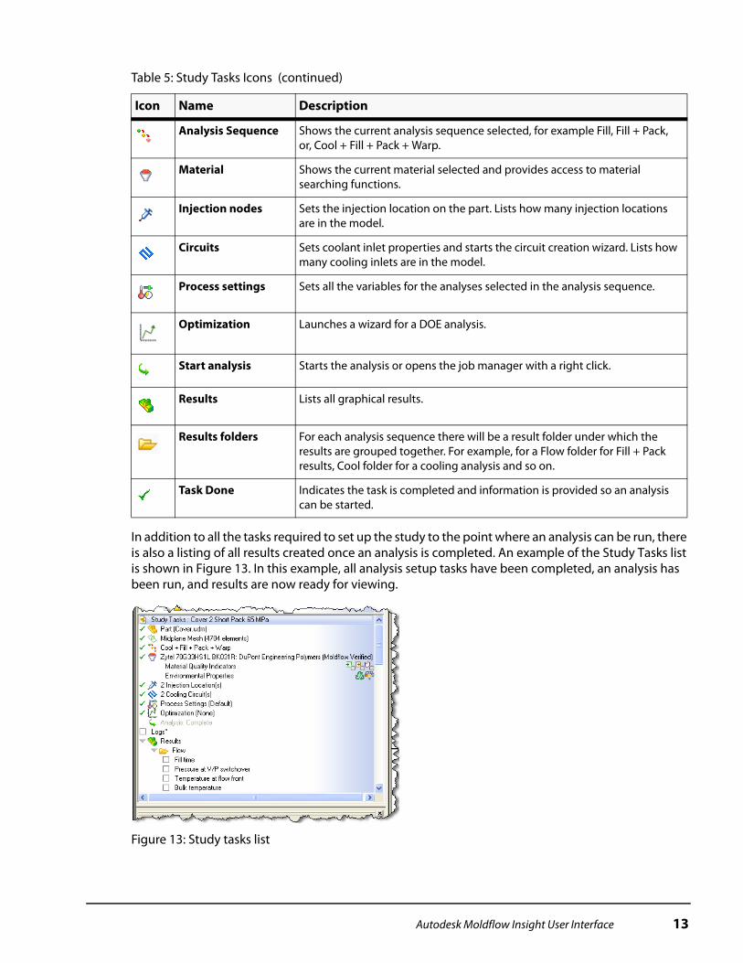
In addition to all the tasks required to set up the study to the point where an analysis can be run, there is also a listing of all results created once an analysis is completed. An example of the Study Tasks list is shown in Figure 13. In this example, all analysis setup tasks have been completed, an analysis has been run, and results are now ready for viewing.
Figure 13: Study tasks list
Analysis Sequence Shows the current analysis sequence selected, for example Fill, Fill + Pack, or, Cool + Fill + Pack + Warp.
Material Shows the current material selected and provides access to material searching functions.
Injection nodes Sets the injection location on the part. Lists how many injection locations are in the model.
Circuits Sets coolant inlet properties and starts the circuit creation wizard. Lists how many cooling inlets are in the model.
Process settings Sets all the variables for the analyses selected in the analysis sequence.
Optimization Launches a wizard for a DOE analysis.
Start analysis Starts the analysis or opens the job manager with a right click.
Results Lists all graphical results.
Results folders For each analysis sequence there will be a result folder under which the results are grouped together. For example, for a Flow folder for Fill + Pack results, Cool folder for a cooling analysis and so on.
Task Done Indicates the task is completed and information is provided so an analysis can be started.
Table 5: Study Tasks Icons (continued)
Icon Name Description
Autodesk Moldflow Insight User Interface 13
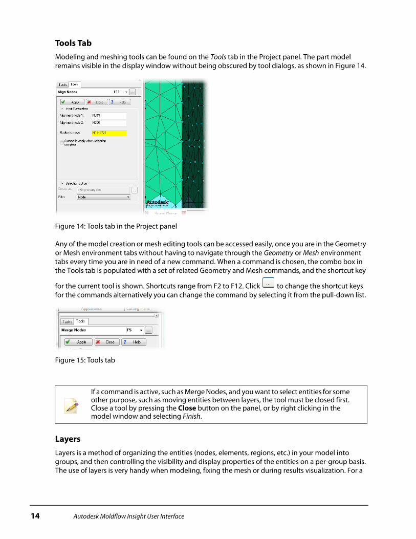
Tools TabModeling and meshing tools can be found on the Tools tab in the Project panel. The part model remains visible in the display window without being obscured by tool dialogs, as shown in Figure 14.
Figure 14: Tools tab in the Project panel
Any of the model creation or mesh editing tools can be accessed easily, once you are in the Geometry or Mesh environment tabs without having to navigate through the Geometry or Mesh environment tabs every time you are in need of a new command. When a command is chosen, the combo box in the Tools tab is populated with a set of related Geometry and Mesh commands, and the shortcut key
for the current tool is shown. Shortcuts range from F2 to F12. Click to change the shortcut keys for the commands alternatively you can change the command by selecting it from the pull-down list.
Figure 15: Tools tab
LayersLayers is a method of organizing the entities (nodes, elements, regions, etc.) in your model into groups, and then controlling the visibility and display properties of the entities on a per-group basis. The use of layers is very handy when modeling, fixing the mesh or during results visualization. For a
If a command is active, such as Merge Nodes, and you want to select entities for some other purpose, such as moving entities between layers, the tool must be closed first. Close a tool by pressing the Close button on the panel, or by right clicking in the model window and selecting Finish.
14 Autodesk Moldflow Insight User Interface

model that has been meshed, there will be several default layers, including: Default Layer, New Nodes, and New Triangles. There will also be one or two layers for the imported geometry. Layers can also be organized to represent geometries, such as runners, gates, edge, top, side, etc.
The Layers pane is by default, located under the Tasks/tools pane. The Layers pane can be a floating dialog. To make the pane float, simple click in the icon area of the pane and drag it of the panel.
In the layers pane shown in Figure 16, several details can be seen including:
The bold layer is the active layer. Any new geometry that you create, for example a runner system, will be added to this layer.
The layers with a tick in the check box are visible layers. All entities assigned to those layers will be visible on the screen.
The highlighted layer with the blue background is the currently selected layer. Most of the layer commands work on the highlighted layer as described in Figure 16.
Figure 16: Layers pane
A complete list of commands and actions available for layers are shown in Table 6.
Results can be automatically scaled by visible layers. Layers can be created at any time to aid in viewing results.
An entity can be only on one layer at a time.
Table 6: Layer icons
Icon Command Action
Create Layer Creates a new layer. Once created, you may click on the name to change it.
Delete Layer Deletes the highlighted layer. If there are any entities on that layer, you will be prompted to delete the entities or to move the entities to the active layer.
Autodesk Moldflow Insight User Interface 15
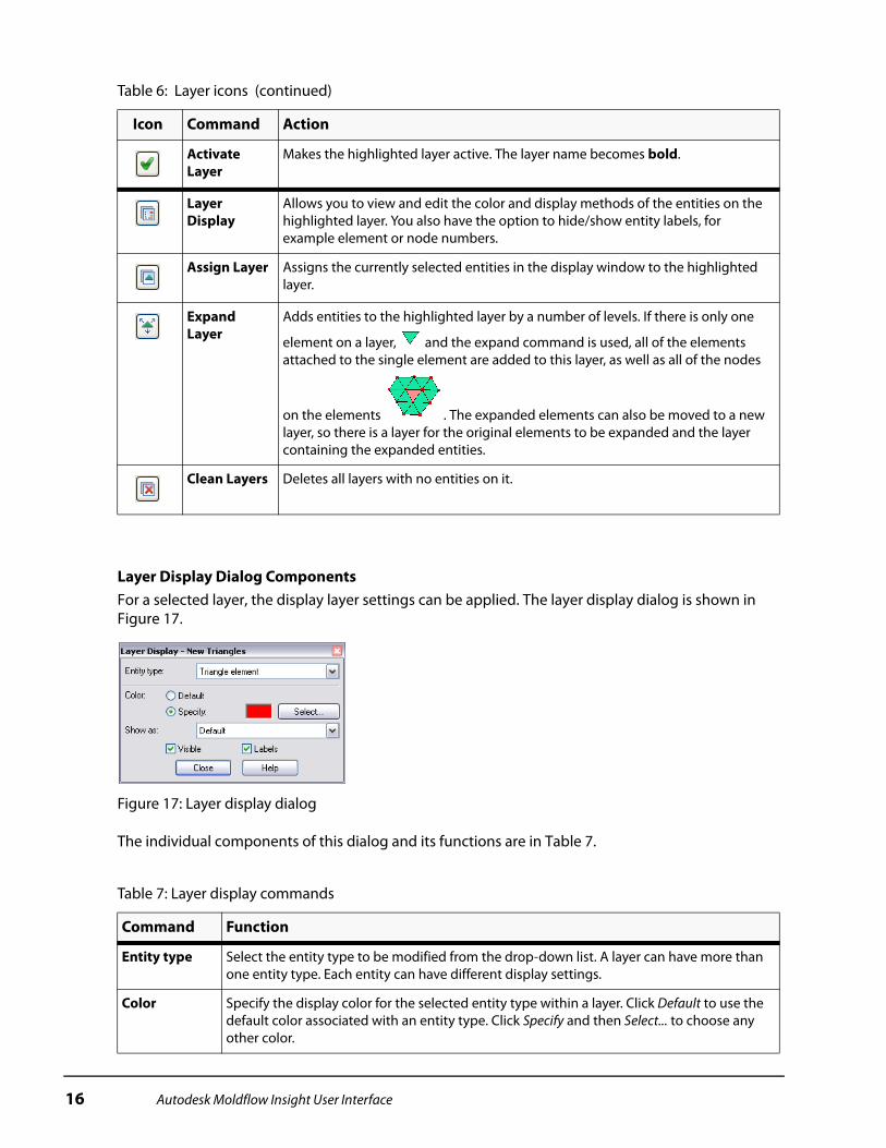
Layer Display Dialog ComponentsFor a selected layer, the display layer settings can be applied. The layer display dialog is shown in Figure 17.
Figure 17: Layer display dialog
The individual components of this dialog and its functions are in Table 7.
Activate Layer
Makes the highlighted layer active. The layer name becomes bold.
Layer Display
Allows you to view and edit the color and display methods of the entities on the highlighted layer. You also have the option to hide/show entity labels, for example element or node numbers.
Assign Layer Assigns the currently selected entities in the display window to the highlighted layer.
Expand Layer
Adds entities to the highlighted layer by a number of levels. If there is only one
element on a layer, and the expand command is used, all of the elements attached to the single element are added to this layer, as well as all of the nodes
on the elements . The expanded elements can also be moved to a new layer, so there is a layer for the original elements to be expanded and the layer containing the expanded entities.
Clean Layers Deletes all layers with no entities on it.
Table 7: Layer display commands
Command Function
Entity type Select the entity type to be modified from the drop-down list. A layer can have more than one entity type. Each entity can have different display settings.
Color Specify the display color for the selected entity type within a layer. Click Default to use the default color associated with an entity type. Click Specify and then Select... to choose any other color.
Table 6: Layer icons (continued)
Icon Command Action
16 Autodesk Moldflow Insight User Interface
Layer context menuThe context menu (right click) for the layers area is particularly beneficial. In addition to the same commands as the icons on the layer toolbar, there are other commands that are useful. Table 8 lists the commands on the layers context menu.
Show as Specify the display method for each entity type within a layer. From the drop-down list, select a display method. The display method changes depending on the type of entity. For elements the list is:
Default. Solid. Solid + Element Edges. Transparent. Transparent + Element Edges. Shrunken.
Visible Specify whether each entity type within a layer is visible, or hidden. Click in the box to turn visibility on or off.
Labels Display on or off the labels of each entity type.
Table 8: Layer commands found on the context menu
Command Description
Make Active Makes the highlighted layer active. Described in detail in Table 6.
Assign Moves selected entities to highlighted layer. Described in detail in Table 6.
Display Changes the display properties for entities on the highlighted layer. Described in detail in Table 6.
Expand Adds nodes and elements to entities on the highlighted layer. Described in detail in Table 6.
Delete Deletes the highlighted layer. Described in detail in Table 6.
Rename Change the name of the highlighted layer.
Labels Turns on entity labels (Node numbers for example) for the highlighted layer.
Show all Layers Turns on all layers.
Hide all Other Layers Turns off all layers except the highlighted layer.
Move Up Moves the highlighted layer up one spot in the layer list.
Move Down Moves the highlighted layer down one spot in the layer list.
Table 7: Layer display commands (continued)
Command Function
Autodesk Moldflow Insight User Interface 17
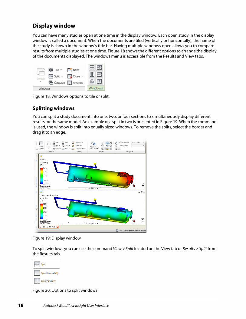
Display windowYou can have many studies open at one time in the display window. Each open study in the display window is called a document. When the documents are tiled (vertically or horizontally), the name of the study is shown in the window’s title bar. Having multiple windows open allows you to compare results from multiple studies at one time. Figure 18 shows the different options to arrange the display of the documents displayed. The windows menu is accessible from the Results and View tabs.
Figure 18: Windows options to tile or split.
Splitting windowsYou can split a study document into one, two, or four sections to simultaneously display different results for the same model. An example of a split in two is presented in Figure 19. When the command is used, the window is split into equally sized windows. To remove the splits, select the border and drag it to an edge.
Figure 19: Display window
To split windows you can use the command View > Split located on the View tab or Results > Split from the Results tab.
Figure 20: Options to split windows
18 Autodesk Moldflow Insight User Interface
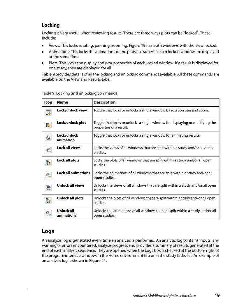
LockingLocking is very useful when reviewing results. There are three ways plots can be “locked”. These include:
Views: This locks rotating, panning, zooming. Figure 19 has both windows with the view locked. Animations: This locks the animations of the plots so frames in each locked window are displayed
at the same time. Plots: This locks the display and plot properties of each locked window. If a result is displayed for
one study, they are displayed for all.Table 9 provides details of all the locking and unlocking commands available. All these commands are available on the View and Results tabs.
LogsAn analysis log is generated every time an analysis is performed. An analysis log contains inputs, any warning or errors encountered, analysis progress and provides a summary of results generated at the end of each analysis sequence. They are opened when the Logs box is checked at the bottom right of the program interface window, in the Home environment tab or in the study tasks list. An example of an analysis log is shown in Figure 21.
Table 9: Locking and unlocking commands
Icon Name Description
Lock/unlock view Toggle that locks or unlocks a single window by rotation pan and zoom.
Lock/unlock plot Toggle that locks or unlocks a single window for displaying or modifying the properties of a result.
Lock/unlock animation
Toggle that locks or unlocks a single window for animating results.
Lock all views Locks the views of all windows that are split within a study and/or all open studies.
Lock all plots Locks the plots of all windows that are split within a study and/or all open studies.
Lock all animations Locks the animations of all windows that are split within a study and/or all open studies.
Unlock all views Unlocks the views of all windows that are split within a study and/or all open studies.
Unlock all plots Unlocks the plots of all windows that are split within a study and/or all open studies.
Unlock all animations
Unlocks the animations of all windows that are split within a study and/or all open studies.
Autodesk Moldflow Insight User Interface 19

Figure 21: Analysis log for a study in Synergy
The tabs on the analysis log window depends on the analysis sequence selected when running the analysis.
The Analysis Log and Fill + Pack tabs are very similar files. The Analysis Log has more details showing the actual running of the analysis. Both contain useful information about the overall analysis to get a sense for how the analysis ran and if there are any major problems.
Notes panelThe Notes panel is off by default. It can be turned on from the View tab, select the command User Interface > Notes. Its default location is on the right side of the screen, as shown in Figure 22. It has two tabs, one for Study notes, and one for plot notes. Study notes get copied with the study and plot notes do not. There is a different plot note for every result.
Figure 22: Notes panel on the right side of the screen
20 Autodesk Moldflow Insight User Interface
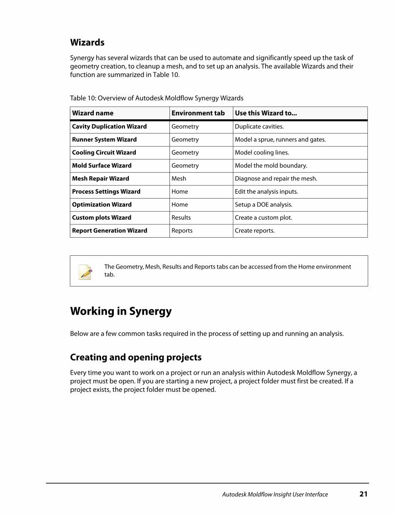
WizardsSynergy has several wizards that can be used to automate and significantly speed up the task of geometry creation, to cleanup a mesh, and to set up an analysis. The available Wizards and their function are summarized in Table 10.
Working in Synergy
Below are a few common tasks required in the process of setting up and running an analysis.
Creating and opening projectsEvery time you want to work on a project or run an analysis within Autodesk Moldflow Synergy, a project must be open. If you are starting a new project, a project folder must first be created. If a project exists, the project folder must be opened.
Table 10: Overview of Autodesk Moldflow Synergy Wizards
Wizard name Environment tab Use this Wizard to...
Cavity Duplication Wizard Geometry Duplicate cavities.
Runner System Wizard Geometry Model a sprue, runners and gates.
Cooling Circuit Wizard Geometry Model cooling lines.
Mold Surface Wizard Geometry Model the mold boundary.
Mesh Repair Wizard Mesh Diagnose and repair the mesh.
Process Settings Wizard Home Edit the analysis inputs.
Optimization Wizard Home Setup a DOE analysis.
Custom plots Wizard Results Create a custom plot.
Report Generation Wizard Reports Create reports.
The Geometry, Mesh, Results and Reports tabs can be accessed from the Home environment tab.
Autodesk Moldflow Insight User Interface 21
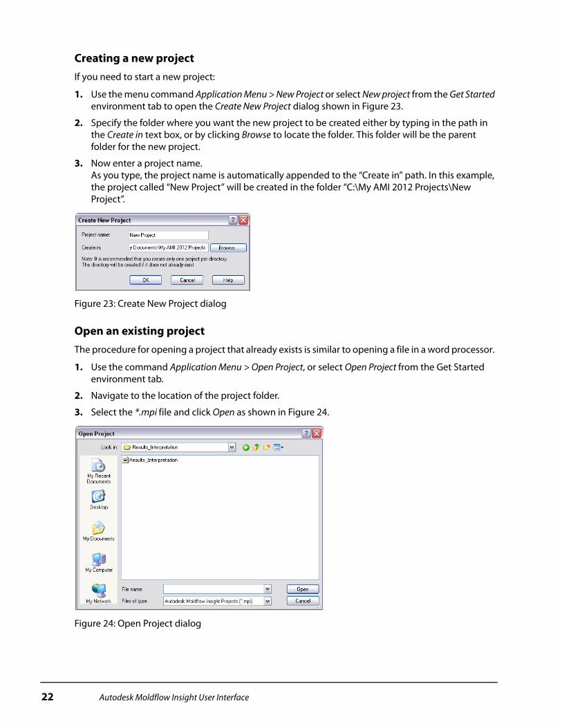
Creating a new projectIf you need to start a new project:
1. Use the menu command Application Menu > New Project or select New project from the Get Started environment tab to open the Create New Project dialog shown in Figure 23.
2. Specify the folder where you want the new project to be created either by typing in the path in the Create in text box, or by clicking Browse to locate the folder. This folder will be the parent folder for the new project.
3. Now enter a project name. As you type, the project name is automatically appended to the “Create in” path. In this example, the project called “New Project” will be created in the folder “C:\My AMI 2012 Projects\New Project”.
Figure 23: Create New Project dialog
Open an existing projectThe procedure for opening a project that already exists is similar to opening a file in a word processor.
1. Use the command Application Menu > Open Project, or select Open Project from the Get Started environment tab.
2. Navigate to the location of the project folder.
3. Select the *.mpi file and click Open as shown in Figure 24.
Figure 24: Open Project dialog
22 Autodesk Moldflow Insight User Interface

OptionsIn the Application menu, there is a command called Options that displays a dialog shown in Figure 25, with many settings for Synergy. There are several categories of options settings, including:
Figure 25: Options dialog
There are a few options that are commonly changed by users - these are summarized in Table 11.
General Results Viewer Internet
Directories External applications Background and Colors Reports
Mouse Default Display Language and Help System
Table 11: Common changes made to options
Tab Options Use this options to...
General Active units Switch between English and Metric units. This can be done at any time.
General Auto-save every
Turn the auto-save function on or off, and to specify at what frequency the auto-save is to be performed.
General Modeling plane
Specify the size of the grid on the modeling plane, and to turn the snap-to-grid feature on or off.
Directories Default import directory
Specify your preferred import directory. If selected, the file import dialog will always open the project directory. If not selected, the dialog will open the last directory where you imported a model. It is sometimes handy to toggle this check box depending on where the files to be imported are located.
Directories Project directory
This defines the location of the project directory. By default new projects will default to this location.
Autodesk Moldflow Insight User Interface 23
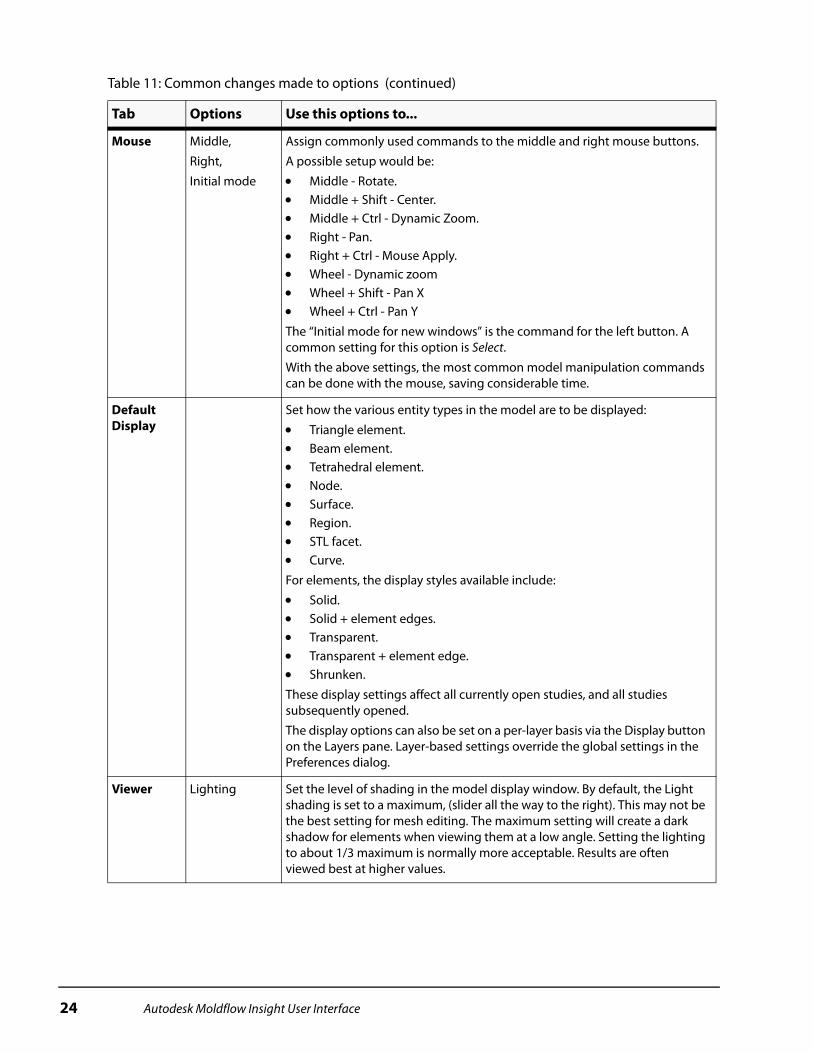
Mouse Middle,
Right,
Initial mode
Assign commonly used commands to the middle and right mouse buttons.
A possible setup would be:
Middle - Rotate. Middle + Shift - Center. Middle + Ctrl - Dynamic Zoom. Right - Pan. Right + Ctrl - Mouse Apply. Wheel - Dynamic zoom Wheel + Shift - Pan X Wheel + Ctrl - Pan Y
The “Initial mode for new windows” is the command for the left button. A common setting for this option is Select.
With the above settings, the most common model manipulation commands can be done with the mouse, saving considerable time.
Default Display
Set how the various entity types in the model are to be displayed:
Triangle element. Beam element. Tetrahedral element. Node. Surface. Region. STL facet. Curve.
For elements, the display styles available include:
Solid. Solid + element edges. Transparent. Transparent + element edge. Shrunken.
These display settings affect all currently open studies, and all studies subsequently opened.
The display options can also be set on a per-layer basis via the Display button on the Layers pane. Layer-based settings override the global settings in the Preferences dialog.
Viewer Lighting Set the level of shading in the model display window. By default, the Light shading is set to a maximum, (slider all the way to the right). This may not be the best setting for mesh editing. The maximum setting will create a dark shadow for elements when viewing them at a low angle. Setting the lighting to about 1/3 maximum is normally more acceptable. Results are often viewed best at higher values.
Table 11: Common changes made to options (continued)
Tab Options Use this options to...
24 Autodesk Moldflow Insight User Interface

Model manipulationThe tools that are commonly used to manipulate the model are summarized in Table 12. These tools are located on the View environment tab and Navigation bar in the display window, as shown in Figure 26. They are also available in the context menu that appears when you right-click in the display window.
Figure 26: Model manipulation tools (display window (left) View environment tab (right))
Results Default results Set the default results to show in the Study Tasks pane when an analysis is complete. To add more results to the default results list, click Add/Remove, then select them in the All Results list and click >> to move them to the Default results list. There are also options for overcoming memory limitations when viewing results for large models.
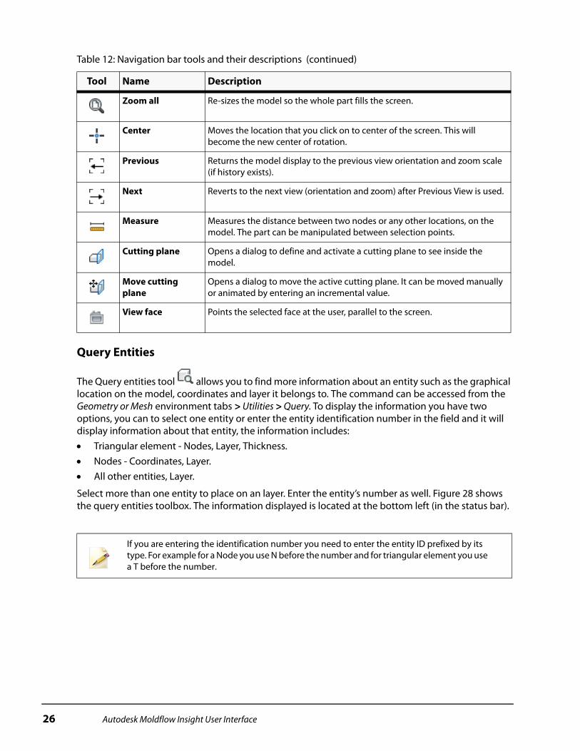
Table 12: Navigation bar tools and their descriptions
Tool Name Description
Select Selects the part or entities.
Rotate Rotates the part within the display.
Pan Moves the part within the display.
Zoom Increases/decreases the model magnification as you hold the left mouse button and drag the cursor up or down the screen.
Zoom window Zooms in an area that you select by banding.
Table 11: Common changes made to options (continued)
Tab Options Use this options to...
Autodesk Moldflow Insight User Interface 25
Query Entities
The Query entities tool allows you to find more information about an entity such as the graphical location on the model, coordinates and layer it belongs to. The command can be accessed from the Geometry or Mesh environment tabs > Utilities > Query. To display the information you have two options, you can to select one entity or enter the entity identification number in the field and it will display information about that entity, the information includes: Triangular element - Nodes, Layer, Thickness. Nodes - Coordinates, Layer. All other entities, Layer.
Select more than one entity to place on an layer. Enter the entity’s number as well. Figure 28 shows the query entities toolbox. The information displayed is located at the bottom left (in the status bar).
Zoom all Re-sizes the model so the whole part fills the screen.
Center Moves the location that you click on to center of the screen. This will become the new center of rotation.
Previous Returns the model display to the previous view orientation and zoom scale (if history exists).
Next Reverts to the next view (orientation and zoom) after Previous View is used.
Measure Measures the distance between two nodes or any other locations, on the model. The part can be manipulated between selection points.
Cutting plane Opens a dialog to define and activate a cutting plane to see inside the model.
Move cutting plane
Opens a dialog to move the active cutting plane. It can be moved manually or animated by entering an incremental value.
View face Points the selected face at the user, parallel to the screen.
If you are entering the identification number you need to enter the entity ID prefixed by its type. For example for a Node you use N before the number and for triangular element you use a T before the number.
Table 12: Navigation bar tools and their descriptions (continued)
Tool Name Description
26 Autodesk Moldflow Insight User Interface
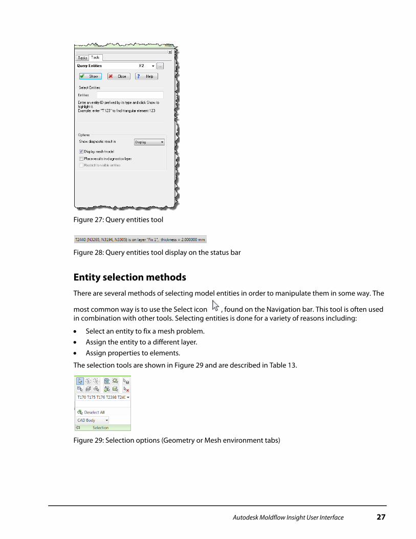
Figure 27: Query entities tool
Figure 28: Query entities tool display on the status bar
Entity selection methodsThere are several methods of selecting model entities in order to manipulate them in some way. The
most common way is to use the Select icon , found on the Navigation bar. This tool is often used in combination with other tools. Selecting entities is done for a variety of reasons including:
Select an entity to fix a mesh problem. Assign the entity to a different layer. Assign properties to elements.
The selection tools are shown in Figure 29 and are described in Table 13.
Figure 29: Selection options (Geometry or Mesh environment tabs)
Autodesk Moldflow Insight User Interface 27
Selected elements are shown in a color defined by the Active selection color option in the General page of the Options. The default color is pink, see Figure 30.
Several selection methods can be used at the same time. A banded selection can be used for making a selection. Then by holding down the CTRL key, the banded selection can be used again. When the control key is depressed, individual elements can be selected by clicking on them.
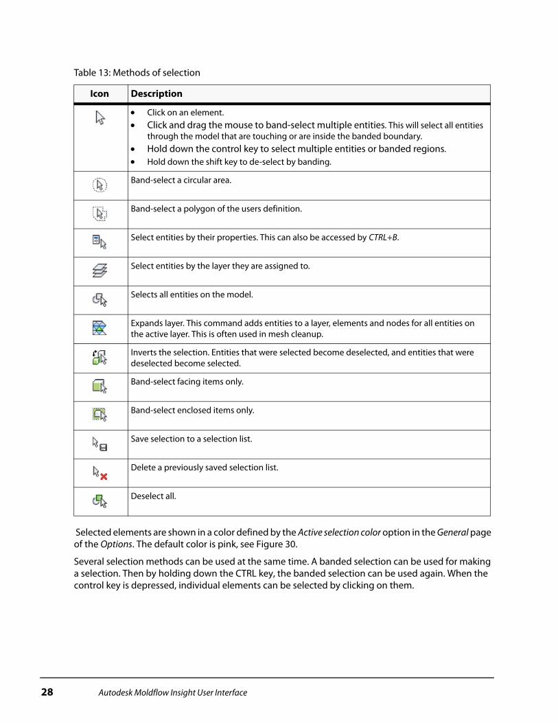
Table 13: Methods of selection
Icon Description
Click on an element. Click and drag the mouse to band-select multiple entities. This will select all entities
through the model that are touching or are inside the banded boundary. Hold down the control key to select multiple entities or banded regions. Hold down the shift key to de-select by banding.
Band-select a circular area.
Band-select a polygon of the users definition.
Select entities by their properties. This can also be accessed by CTRL+B.
Select entities by the layer they are assigned to.
Selects all entities on the model.
Expands layer. This command adds entities to a layer, elements and nodes for all entities on the active layer. This is often used in mesh cleanup.
Inverts the selection. Entities that were selected become deselected, and entities that were deselected become selected.
Band-select facing items only.
Band-select enclosed items only.
Save selection to a selection list.
Delete a previously saved selection list.
Deselect all.
28 Autodesk Moldflow Insight User Interface

Figure 30: Selected elements
Entity selections can also be saved as a list in the Select Saved Selection List on the Selection toolbar, shown in Figure 31. When entities are selected on a model, the entire list of entities is updated into the Select Saved Selection List field.
Figure 31: Selected entities listed in the Select Saved Selection List (located in the Geometry or Mesh environment tabs)
To save the list, select the Save Selection List icon and enter a name. To retrieve the saved list for use at a later time, click on the drop-down arrow and select the name that you entered. This is a useful feature if you are performing repetitive tasks with the same group of model entities.
The selection list is integrated with the Geometry and Mesh tools. Notice that the saved selected entities are available for selection in other dialogs as shown in Figure 32.
Figure 32: Selection list usage
Working with propertiesProperties are characteristics of entities in a model, typically elements. They are grouped together depending on the type of entity. For instance, there are different properties for beam elements that are used to define runners, gates, sprues, water channels, etc. There are also properties for triangular elements that are used to define midplane or Dual Domain models.
When working with properties, there are two basic approaches: edit an existing property or create a new one. The preferred method to use depends on the situation.
Autodesk Moldflow Insight User Interface 29
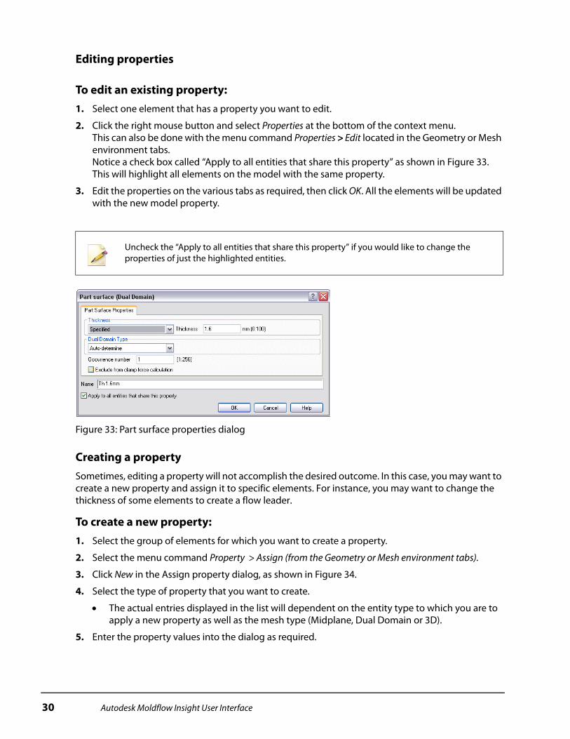
Editing properties
To edit an existing property:1. Select one element that has a property you want to edit.
2. Click the right mouse button and select Properties at the bottom of the context menu. This can also be done with the menu command Properties > Edit located in the Geometry or Mesh environment tabs. Notice a check box called “Apply to all entities that share this property” as shown in Figure 33. This will highlight all elements on the model with the same property.
3. Edit the properties on the various tabs as required, then click OK. All the elements will be updated with the new model property.
Figure 33: Part surface properties dialog
Creating a propertySometimes, editing a property will not accomplish the desired outcome. In this case, you may want to create a new property and assign it to specific elements. For instance, you may want to change the thickness of some elements to create a flow leader.
To create a new property:1. Select the group of elements for which you want to create a property.
2. Select the menu command Property > Assign (from the Geometry or Mesh environment tabs).
3. Click New in the Assign property dialog, as shown in Figure 34.
4. Select the type of property that you want to create.
The actual entries displayed in the list will dependent on the entity type to which you are to apply a new property as well as the mesh type (Midplane, Dual Domain or 3D).
5. Enter the property values into the dialog as required.
Uncheck the “Apply to all entities that share this property” if you would like to change the properties of just the highlighted entities.
30 Autodesk Moldflow Insight User Interface
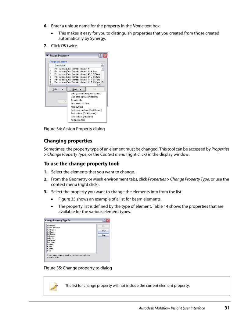
6. Enter a unique name for the property in the Name text box.
This makes it easy for you to distinguish properties that you created from those created automatically by Synergy.
7. Click OK twice.
Figure 34: Assign Property dialog
Changing propertiesSometimes, the property type of an element must be changed. This tool can be accessed by Properties > Change Property Type, or the Context menu (right click) in the display window.
To use the change property tool:1. Select the elements that you want to change.
2. From the Geometry or Mesh environment tabs, click Properties > Change Property Type, or use the context menu (right click).
3. Select the property you want to change the elements into from the list.
Figure 35 shows an example of a list for beam elements.
The property list is defined by the type of element. Table 14 shows the properties that are available for the various element types.
Figure 35: Change property to dialog
The list for change property will not include the current element property.
Autodesk Moldflow Insight User Interface 31

When beam elements are selected and changed, a message will appear after the change indicating the parent curves for the beam elements are also changed, similar to the message shown in Figure 36.
Figure 36: Message indicating curves were changed with the beams
How element properties are affected by property changes Dual Domain elements.
When geometry is meshed, say an IGES file, as a Dual Domain mesh, there are many properties created. Each property has the thickness set to Auto-determine, but it also has a specified thickness that is calculated and available. The name of the property contains the thickness. If the property type was changed to Mold insert surface, for example, there would be a new Mold insert surface property for every Part Surface (Dual Domain) property that was converted. Normally, only one property is needed to represent all Mold insert surfaces. To reduce the number of properties, all
Table 14: Properties available by element type
Beam elements
Dual Domain elements Midplane elements Tetrahedral elements
Connector Part surface (Midplane) Part surface (Midplane) Part (3D)
Critical dimension
Part surface (Dual Domain) Cold gate surface (Midplane) Hot runner (3D)
Cold gate Cold gate surface (Midplane) Mold surface Cold runner (3D)
Cold runner Cold gate surface (Dual Domain) In-mold label Part insert (3D)
Cold sprue Mold surface Part insert surface (Midplane) Core (3D)
Hot runner In-mold label Mold insert surface Mold block (3D)
Hot gate Mold insert surface Parting surface Mold insert (3D)
Hot sprue Part insert surface (Dual Domain)
Part beam Parting surface
Channel
Baffle
Bubbler
Hose
Cartridge heater
32 Autodesk Moldflow Insight User Interface

the converted Mold insert surface elements can be reassigned to one property. If the elements with the Mold insert surface was then converted back to Part surface (Dual Domain), the thickness would be set back to Auto-determine, with no specified thickness. The solvers would properly calculate the thickness for the elements.
Midplane elements.If the mesh was midplane and the elements were converted from Part surface (midplane) to Mold insert surface, then back to Part surface (midplane) the thickness would get set back to a default value, effectively loosing the correct thickness value.
Beam elements.For beam elements, the conversion is more straight forward. A runner can be converted to a gate. The gate would originally have the same cross-section and size as the runner, but could then be changed by editing the properties like would be done normally.
Tetrahedral elements.Like beam elements, the conversion is straight forward due to not having a thickness as part of the property.
Autodesk Moldflow Insight User Interface 33
Chapter Summary
Synergy is the User interface for Autodesk Moldflow Insight. It has all the tools necessary to:
Import a model. Mesh the model. Clean up the mesh. Set up an analysis. Review results.
There are many ways that commands can be accessed including:
Application menu. Quick access toolbar. Environment tab. Panel.
• Project View.• Study Tasks list.• Layers Pane.
Context menus. Navigation bar.
Most commands have several methods to activate them.
Synergy provides a comprehensive set of user options so that users can tailor the program to meet their specific requirements.
34 Autodesk Moldflow Insight User Interface

Practice - Introduction to Synergy
In this practice you will get to learn the user interface through using some of the common features of Synergy.
Table 1: Model used in the introduction to Synergy practice
Description Model
You will create a project, import the cover model and customize the user interface as you learn about all its features.
Autodesk Moldflow Insight User Interface 35
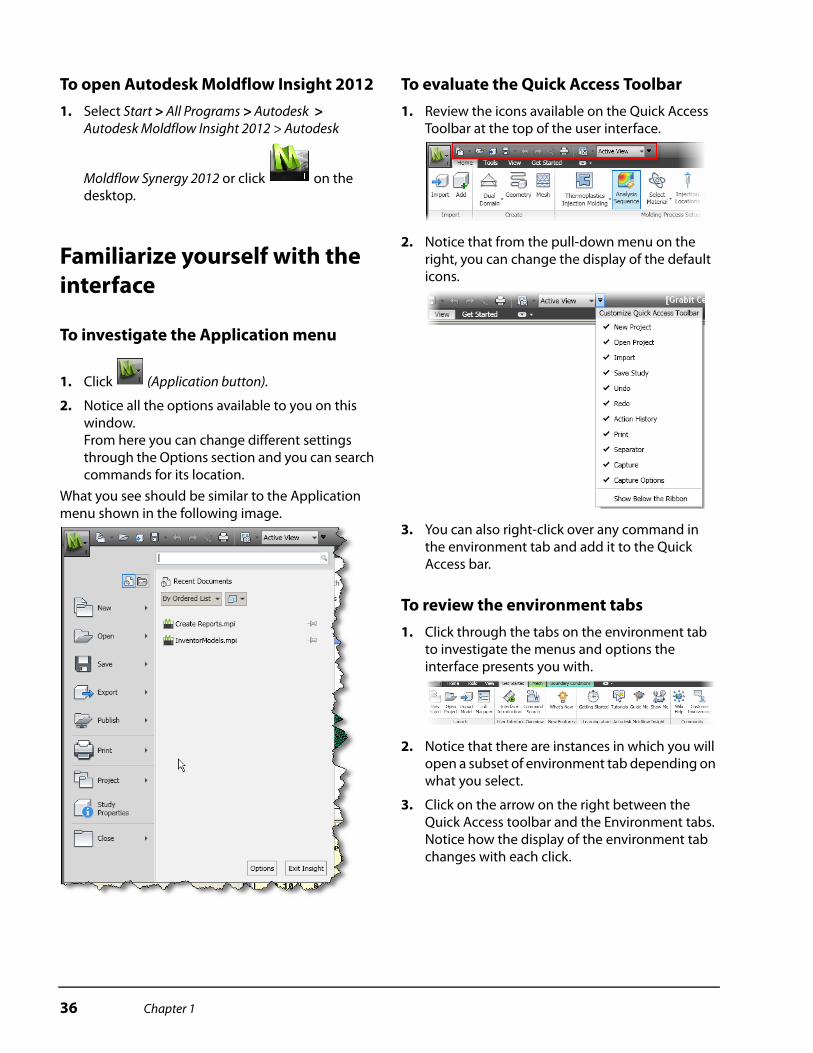
To open Autodesk Moldflow Insight 20121. Select Start > All Programs > Autodesk >
Autodesk Moldflow Insight 2012 > Autodesk
Moldflow Synergy 2012 or click on the desktop.
Familiarize yourself with the interface
To investigate the Application menu
1. Click (Application button).
2. Notice all the options available to you on this window.From here you can change different settings through the Options section and you can search commands for its location.
What you see should be similar to the Application menu shown in the following image.
To evaluate the Quick Access Toolbar1. Review the icons available on the Quick Access
Toolbar at the top of the user interface.
2. Notice that from the pull-down menu on the right, you can change the display of the default icons.
3. You can also right-click over any command in the environment tab and add it to the Quick Access bar.
To review the environment tabs1. Click through the tabs on the environment tab
to investigate the menus and options the interface presents you with.
2. Notice that there are instances in which you will open a subset of environment tab depending on what you select.
3. Click on the arrow on the right between the Quick Access toolbar and the Environment tabs. Notice how the display of the environment tab changes with each click.
36 Chapter 1

To learn the user interface panels1. Select the View tab.
2. In the Windows menu change the options in the User Interface pull-down list.
3. Notice how different sections appear and disappear on the user interface. These menu options are important to remember when working with models.
Working in Synergy
To create a new project1. Select New Project from the Get Started
environment tab.
2. Click Browse… and navigate to the C:\Autodesk Learning\Autodesk Moldflow\UI Practice Files\ folder.
3. Enter Synergy_practice in the Project name text box, and click OK.
To import a model stored in a study file
1. Click (Import, which can be also activated from the Quick Access Toolbar at the top).
Or, right-click the mouse in the Project View and select Import.
2. Navigate to the C:\Autodesk Learning\Autodesk Moldflow\UI Practice Files\extra folder.
3. Click the file cover.sdy to select it, and click Open.
The cover model will be imported into Autodesk Moldflow Insight.
4. Rotate the model and investigate its features.
To define the mouse modesThe first thing that you will do in Synergy is to define the mouse modes, and how the mouse works in conjunction with additional keystrokes, as follows:
1. Select (Application button) located at the top left corner of the user interface.
2. Select Options.
3. Select the Mouse tab to display the options for configuring the mouse modes.
4. Set the following options:
Middle: To Rotate.
Middle+Shift: To Center.
Middle+Ctrl: To Dynamic Zoom.
Right: To Pan.
Right + Ctrl: To Mouse Apply.
Wheel - Dynamic Zoom.
Wheel + Shift - Pan X.
Wheel + Ctrl - Pan Y.
Initial mode for new windows: To Select.
5. Leave the remaining options at their default values and click OK.
To create a new layer
1. Click in the Layers pane, to add a new layer.
2. Enter Rim as the layer name.
When created, the layer name should be highlighted and ready to edit. If not, click the layer to rename it.
In this step, you will assign the rim section of the cover model to the Rim layer that you just created.
The files may not be located in the folder mentioned above. If you are unable to locate the files, consult with your instructor.
If the layer pane is not displayed you can open it by clicking the Layers check box in the User interface menu from the View environment tab.
Chapter 1 37

To assign the rim to the new layer1. Enter –90 –90 0 (-90 space -90 space 0) into the
Rotation Angle text box and click enter.
The rotation angle text box is on the Viewpoint menu in the View environment tab.
Figure 1: Viewpoint menu
2. Select the rim section of the model by creating a banded selection (click, hold and drag the left
mouse button with (Select), as indicated in Figure 2. Start from the lower left corner and drag to the upper right).
If the banded selection is not high enough on the rim, not all of the rim elements will be selected. If the banding goes higher than the rim, part of the top of the part will also be selected and should not be.
If you have selected too much, click in the display area off the model and re-select.
When properly selected, most of the interior elements shown in Figure 3 will be selected and moved to the new Rim layer. These extra elements in the center of the part will be moved back to the New Triangles layer.
Figure 2: Rim section selected
3. Ensure that the Rim layer is highlighted in the
Layers pane, then click (Assign Layer).
This assigns all selected elements to the Rim layer.
4. Enter 0 0 0 into the Rotation Angle text box and click enter, or click Front on the View Cube.
5. De-select the New Triangles layer in the Layers pane.
Notice that there are more elements on the Rim layer than required.
6. Click Select and create a bounding box to select all elements inside the rim, as indicated in Figure 3.
7. Highlight the New Triangles layer, and then click Assign to assign the selected elements back to the New Triangles layer.
Figure 3: Elements inside rim band selected
To set the thickness of the rim layer1. Ensure that only the Rim layer is visible.
2. Click Ctrl + A to select the entire rim.
3. Select Property > Assign (from the Home/Mesh Environment tab).
4. Click New > Part surface (Dual Domain).
5. Select Specified in the Thickness drop-down list, and enter 3 in the text box that appears.
6. Enter 3.0 mm Rim, in the Name text box.
This allows you to uniquely identify the part property at a later time. The large thickness difference value is used to aid the visualization of the changes. Avoid abrupt thickness changes when designing with plastics.
7. Click OK twice.
8. Click Properties > Remove.
This will remove any properties that have no entities assigned to them. Depending on the editing being done, this could be a significant number.
Band to select the inside rim elements
38 Chapter 1
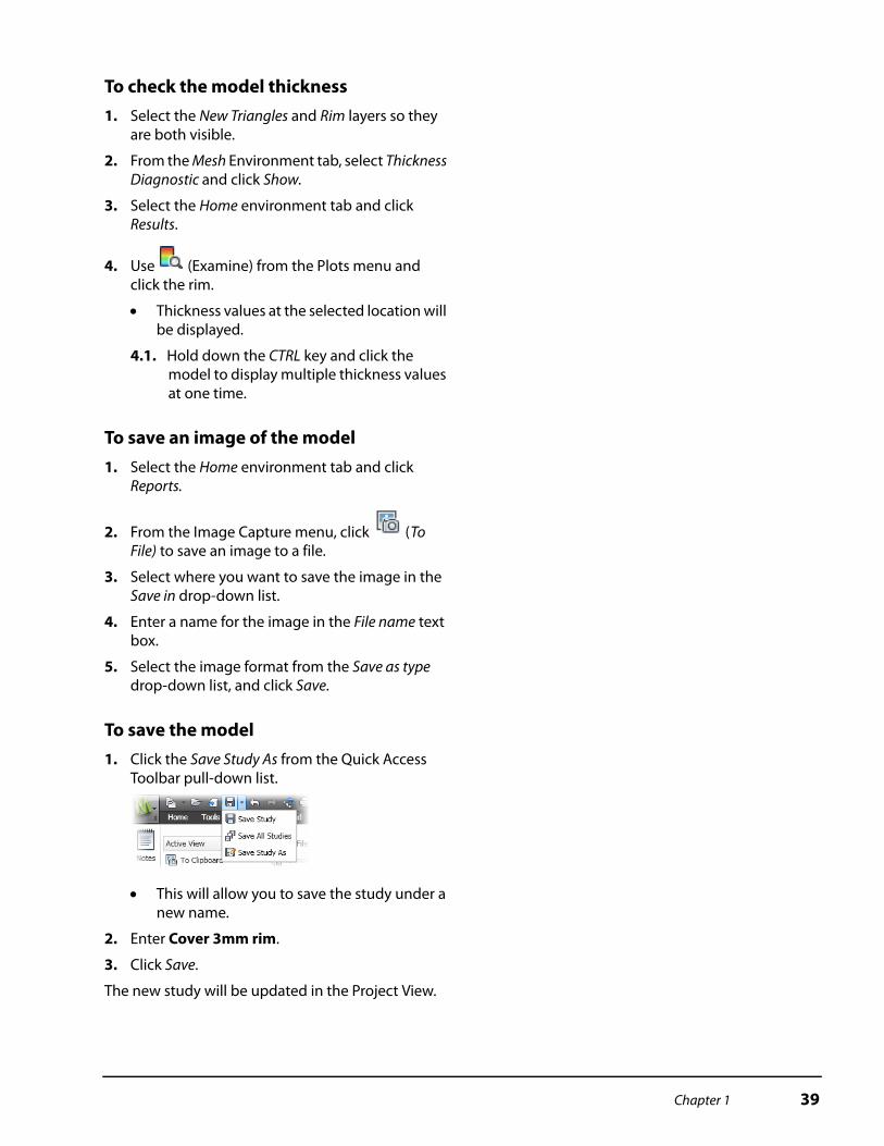
To check the model thickness1. Select the New Triangles and Rim layers so they
are both visible.
2. From the Mesh Environment tab, select Thickness Diagnostic and click Show.
3. Select the Home environment tab and click Results.
4. Use (Examine) from the Plots menu and click the rim.
Thickness values at the selected location will be displayed.
4.1. Hold down the CTRL key and click the model to display multiple thickness values at one time.
To save an image of the model1. Select the Home environment tab and click
Reports.
2. From the Image Capture menu, click (To File) to save an image to a file.
3. Select where you want to save the image in the Save in drop-down list.
4. Enter a name for the image in the File name text box.
5. Select the image format from the Save as type drop-down list, and click Save.
To save the model1. Click the Save Study As from the Quick Access
Toolbar pull-down list.
This will allow you to save the study under a new name.
2. Enter Cover 3mm rim.
3. Click Save.
The new study will be updated in the Project View.
Chapter 1 39
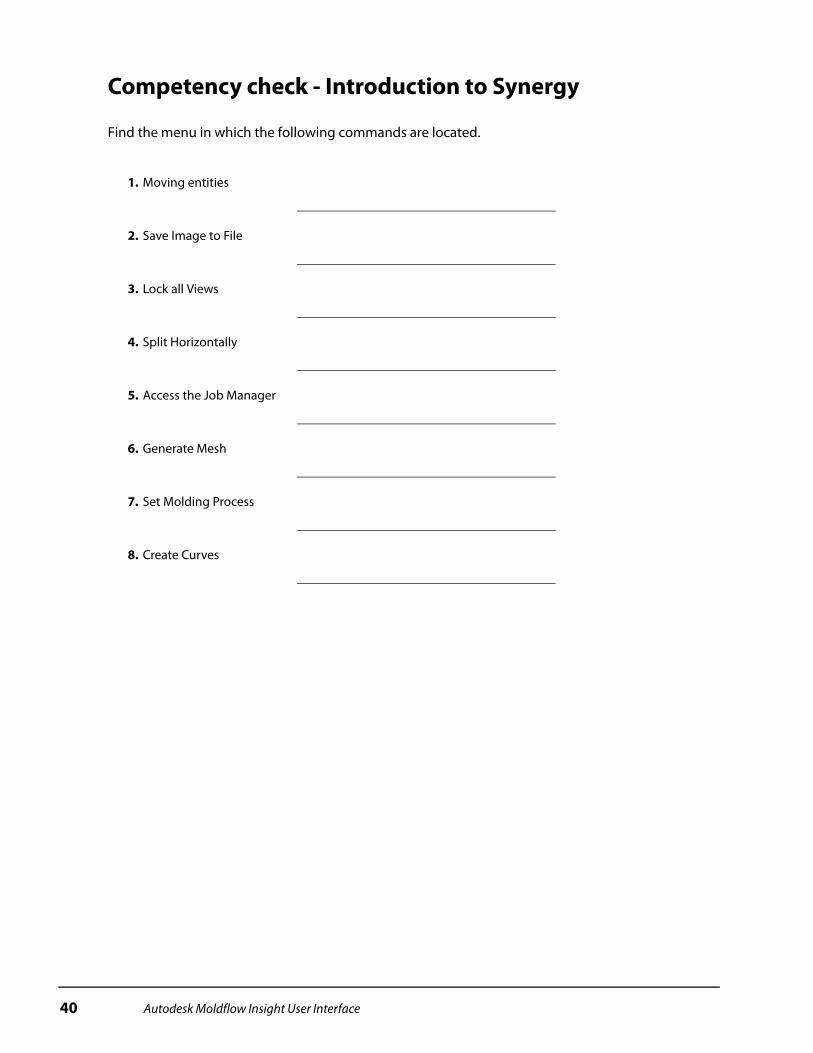
Competency check - Introduction to Synergy
Find the menu in which the following commands are located.
1. Moving entities
2. Save Image to File
3. Lock all Views
4. Split Horizontally
5. Access the Job Manager
6. Generate Mesh
7. Set Molding Process
8. Create Curves
40 Autodesk Moldflow Insight User Interface
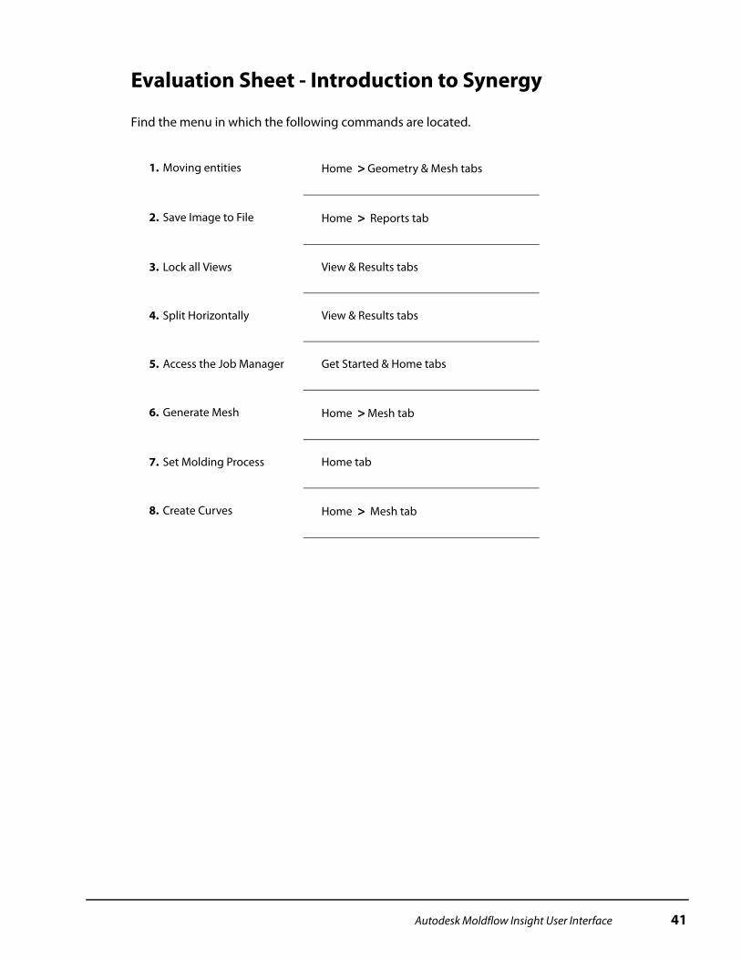
Evaluation Sheet - Introduction to Synergy
Find the menu in which the following commands are located.
1. Moving entities Home > Geometry & Mesh tabs
2. Save Image to File Home > Reports tab
3. Lock all Views View & Results tabs
4. Split Horizontally View & Results tabs
5. Access the Job Manager Get Started & Home tabs
6. Generate Mesh Home > Mesh tab
7. Set Molding Process Home tab
8. Create Curves Home > Mesh tab
Autodesk Moldflow Insight User Interface 41