Introduction To Steel Design · Points on the Stress-Strain Curve • A, is zero stress – zero...
24
Introduction To Steel Design Moayyad Al Nasra, PhD, PE
Transcript of Introduction To Steel Design · Points on the Stress-Strain Curve • A, is zero stress – zero...

Introduction To Steel Design
Moayyad Al Nasra, PhD, PE

Advantages of Steel as Structural Material
• High Strength
• Homogeneous and uniform material
• Elasticity
• Ductility
• Toughness
• Constructability, speed or erection, connectability,
• …Etc.
2 (C) Al Nasra

Disadvantages of Steel As a Structural Material
• Corrosion
• Fireproofing cost
• Susceptibility to buckling
• Fatigue
• Brittle fracture
3 (C) Al Nasra

Iron
• The basic constituent of steel is iron.
• Iron is made from iron ores (limonite (brown ore), hematite (red ore), magnetite)
– Hematite is the most common ore which contains about 70 % iron.
• This mined ore is crushed and placed in a blast furnace (developed by Bessemer in 1860) along with:
• Iron ore
• Coke (heated coal in absence of air)
• Limestone (flux that holds impurities)
• Heat (3000 deg F) and “blast” of air
4 (C) Al Nasra

Iron Products
• Most iron has a high carbon content.
• Wrought iron (very low C content)
– Similar to pure iron, less ductile than steel
• Cast iron (high C content)
– Strong, hard, brittle
• Steel (low C content)
5 (C) Al Nasra

Steel
• Steel is iron with controlled amounts of C and other alloying agents (manganese, silicon, nickel, aluminum, chromium, molybdenum)
• Example: stainless steel is iron, carbon, chromium, nickel (highly resistant to corrosion)
• One cubic foot of steel/iron weighs 490 lbs (490 lb/cu ft)
• Steel properties are affected by: – Chemical composition
– Heat treatment
– Mechanical work
6 (C) Al Nasra
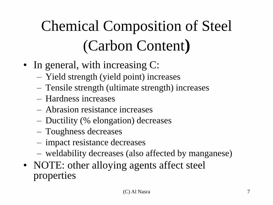
Chemical Composition of Steel
(Carbon Content) • In general, with increasing C:
– Yield strength (yield point) increases
– Tensile strength (ultimate strength) increases
– Hardness increases
– Abrasion resistance increases
– Ductility (% elongation) decreases
– Toughness decreases
– impact resistance decreases
– weldability decreases (also affected by manganese)
• NOTE: other alloying agents affect steel properties
7 (C) Al Nasra

Effect of carbon content on the mechanical properties of steel 8 (C) Al Nasra

Properties of steel • Heat Treatment
– quenching – sudden cooling (produces hard, brittle steel)
– annealing – controlled cooling (produces softer, more ductile steel)
• Mechanical Work
– cold working – working with steel when it’s cold (produces hard, brittle steel)
– hot working – working with steel when it’s hot (produces softer, more ductile steel)
• Mechanical Properties of Steel
– Steel grades indicate its yield strength
– E=29,000 ksi for all steel grades
– Poisson’s ratio = 0.27-0.30
9 (C) Al Nasra

Typical Stress-strain of steel
10 (C) Al Nasra

Iron and Steel
• Steel is defines as a combination of iron and
a small amount of carbon (0.15% to 1.7% ),
usually less than 1%.
• Wrought Iron refers to iron with a very low
carbon content (<0.15%).
• Cast Iron refers to a very high carbon
content (>2%)
11 (C) Al Nasra

Steel Sections
Structural Shapes 12 (C) Al Nasra
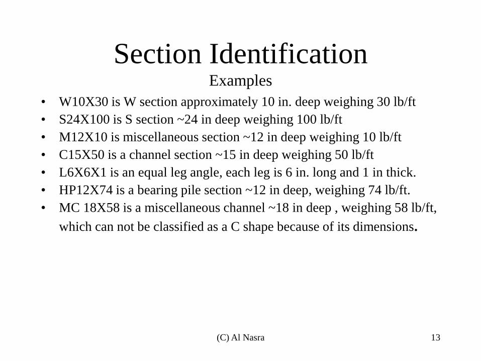
Section Identification Examples
• W10X30 is W section approximately 10 in. deep weighing 30 lb/ft
• S24X100 is S section ~24 in deep weighing 100 lb/ft
• M12X10 is miscellaneous section ~12 in deep weighing 10 lb/ft
• C15X50 is a channel section ~15 in deep weighing 50 lb/ft
• L6X6X1 is an equal leg angle, each leg is 6 in. long and 1 in thick.
• HP12X74 is a bearing pile section ~12 in deep, weighing 74 lb/ft.
• MC 18X58 is a miscellaneous channel ~18 in deep , weighing 58 lb/ft,
which can not be classified as a C shape because of its dimensions.
13 (C) Al Nasra
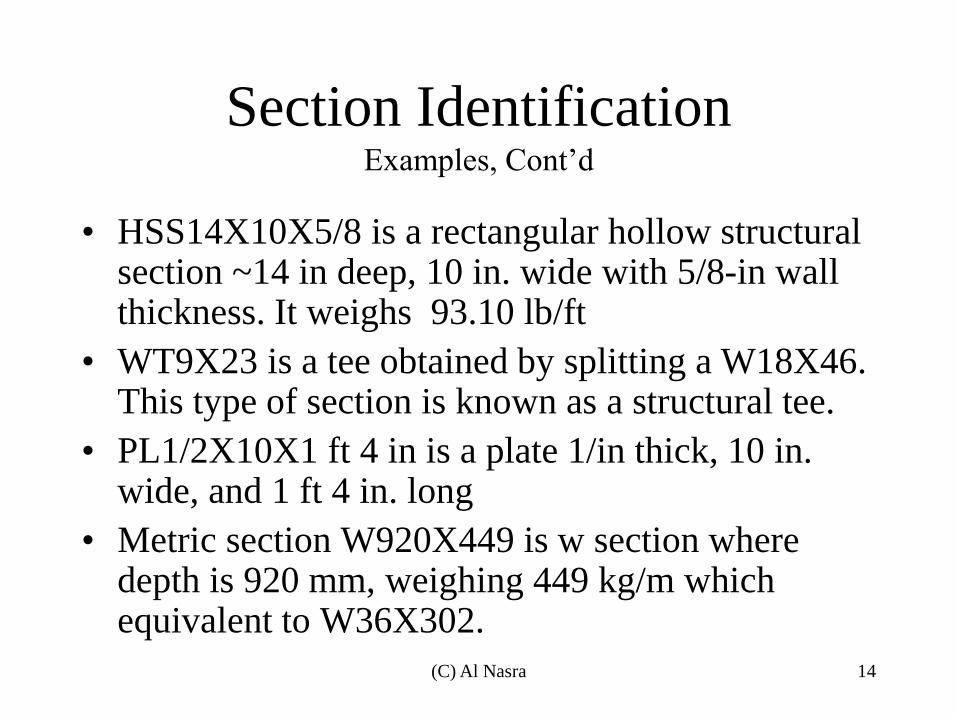
Section Identification Examples, Cont’d
• HSS14X10X5/8 is a rectangular hollow structural section ~14 in deep, 10 in. wide with 5/8-in wall thickness. It weighs 93.10 lb/ft
• WT9X23 is a tee obtained by splitting a W18X46. This type of section is known as a structural tee.
• PL1/2X10X1 ft 4 in is a plate 1/in thick, 10 in. wide, and 1 ft 4 in. long
• Metric section W920X449 is w section where depth is 920 mm, weighing 449 kg/m which equivalent to W36X302.
14 (C) Al Nasra

Stress-Strain Relationship
15 (C) Al Nasra
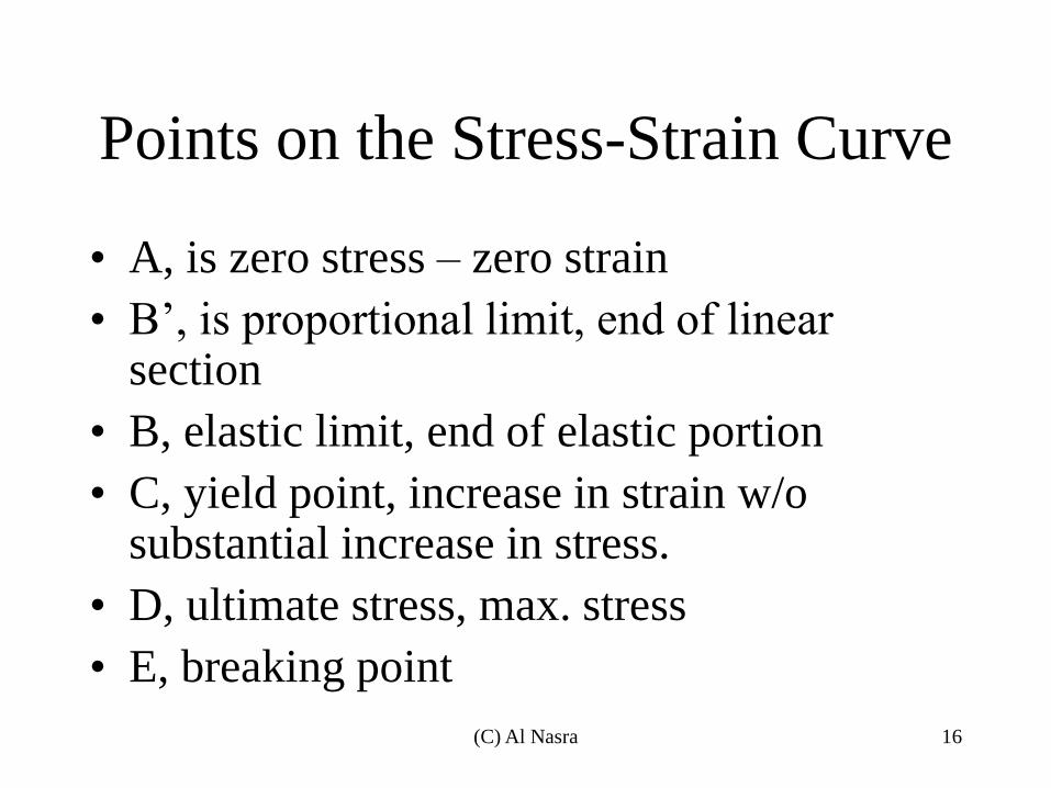
Points on the Stress-Strain Curve
• A, is zero stress – zero strain
• B’, is proportional limit, end of linear section
• B, elastic limit, end of elastic portion
• C, yield point, increase in strain w/o substantial increase in stress.
• D, ultimate stress, max. stress
• E, breaking point
16 (C) Al Nasra
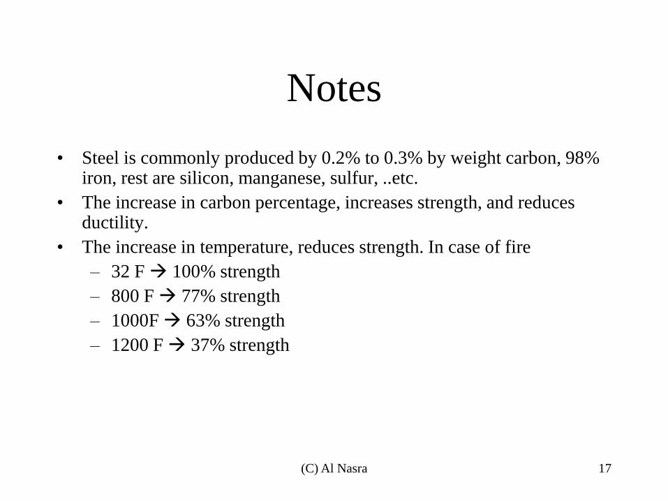
Notes
• Steel is commonly produced by 0.2% to 0.3% by weight carbon, 98% iron, rest are silicon, manganese, sulfur, ..etc.
• The increase in carbon percentage, increases strength, and reduces ductility.
• The increase in temperature, reduces strength. In case of fire
– 32 F 100% strength
– 800 F 77% strength
– 1000F 63% strength
– 1200 F 37% strength
17 (C) Al Nasra
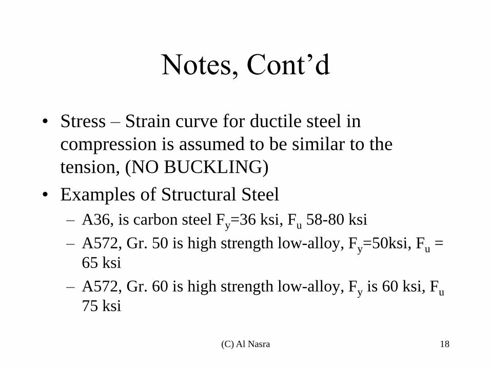
Notes, Cont’d
• Stress – Strain curve for ductile steel in
compression is assumed to be similar to the
tension, (NO BUCKLING)
• Examples of Structural Steel
– A36, is carbon steel Fy=36 ksi, Fu 58-80 ksi
– A572, Gr. 50 is high strength low-alloy, Fy=50ksi, Fu =
65 ksi
– A572, Gr. 60 is high strength low-alloy, Fy is 60 ksi, Fu
75 ksi
18 (C) Al Nasra
Responsibilities of the Structural
Engineer
• Safety
• Cost
• Constructability
19 (C) Al Nasra

Load and Resistance Factor Design (LRFD)
VS
Allowable Strength Design (ASD)
• Similarities
– Both design procedures are based on the limit
states design principles, which provide
boundaries of structural usefulness. The limit
state concept is used to describe a condition at
which a structure or part of a structure ceases to
perform its intended function
20 (C) Al Nasra

Load and Resistance Factor Design (LRFD)
VS
Allowable Strength Design (ASD
• Differences
– LRFD, multiply the service loads by a load
factor (usually >1.0) resulting in factored load
– ASD, the service loads are generally not
multiplied by a load factor
21 (C) Al Nasra
Load and Resistance Factor Design (LRFD)
VS
Allowable Strength Design (ASD)
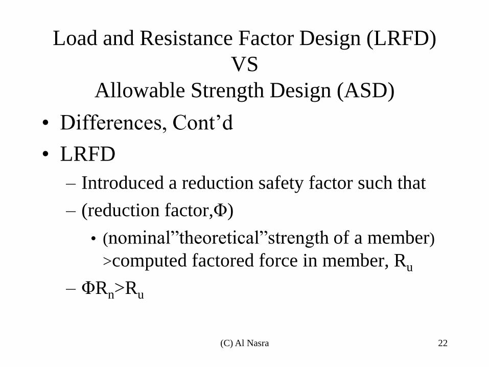
• Differences, Cont’d
• LRFD
– Introduced a reduction safety factor such that
– (reduction factor,Φ)
• (nominal”theoretical”strength of a member)
>computed factored force in member, Ru
– ΦRn>Ru
22 (C) Al Nasra

Load and Resistance Factor Design (LRFD)
VS
Allowable Strength Design (ASD)
• Differences, Cont’d
• ASD
– Introduced a larger safety factor “Ω omega” such that
– (nominal strength of member)/(safety factor=Ω)
>largest computed force in member, Ra
– Rn/Ω>Ra
23 (C) Al Nasra

LRFD VS ASD
– The relationship between the factor of safety and the
resistance factor is, in general
• Ω=1.5/Φ
– (for example if Φ=0.9, Ω=1.5/0.9=1.67)
• The load factors in the linear combination, ζ “xi”, thus if
we set Qi=one of N service loads in a group
ζi= load factor associated with loads in LRFD
Rn= nominal structural strength
Then for LRFD
ΦRn> Σζi.Qi ( i from 1 to N)
And for ASD
(Rn/Ω) > Σ Qi ( i from 1 to N)
24 (C) Al Nasra


![MEAN CURVATURE INTERFACE LIMIT FROM GLAUBER+ZERO … · 2020-04-14 · arXiv:2004.05276v1 [math.PR] 11 Apr 2020 MEAN CURVATURE INTERFACE LIMIT FROM GLAUBER+ZERO-RANGE INTERACTING](https://static.fdocuments.in/doc/165x107/5f0f3d797e708231d4432e06/mean-curvature-interface-limit-from-glauberzero-2020-04-14-arxiv200405276v1.jpg)