Introduction to Solidworks Sheet-Metal Spring/Seminars/Technology... · Introduction to Solidworks...
30
Introduction to Solidworks Sheet-Metal No1: Toothbrush Holder No2: Phone Holder
Transcript of Introduction to Solidworks Sheet-Metal Spring/Seminars/Technology... · Introduction to Solidworks...

Introduction to Solidworks
Sheet-Metal
No1: Toothbrush Holder
No2: Phone Holder

Introduction to Solidworks Sheet Metal for Technology Page 1
Table of Contents
Table of Contents ....................................................................................................................... 1
Exercise 1: Toothbrush Holder ................................................................................................... 2
Exercise 2: Phone Holder ......................................................................................................... 19

Introduction to Solidworks Sheet Metal for Technology Page 2
Exercise 1: Toothbrush Holder
Introduction
This lesson focuses on designing a sheet metal part from the flattened state. In this case,
you create a sheet metal part and then insert bend lines on which to fold the part.
Learning Intentions
At the end of these exercises, you should be able to:
Create a sheet metal part, using Base Flange, Extruded Cut, Sketched Bend and Edit
Material commands
Create a drawing of the sheet metal part
Prerequisite Knowledge
Previous knowledge of the following commands is required to complete this lesson; Sketch
(Line, Centerline, Circle, Add Relations, Smart Dimension,), Extrude Boss/Base, and Edit
Materials. A basic knowledge of the drawing environment is also required
Saving Your Work
Save the file as Toothbrush Holder to a folder called Toothbrush Holder Exercise.
(Continue to save periodically throughout the exercise)

Introduction to Solidworks Sheet Metal for Technology Page 3
Creating the Sheet Metal Part
Getting Started
In order to begin working with Sheet Metal
you must first activate the sheet metal tab on
the command manager.
To activate this tab, right click on the command
manager. Choose Sheet Metal from the drop-
down list.
The Sheet Metal tab is now
active on the command
manager.
Note: The Sheet Metal commands are also available from the drop down menu by selecting
“Insert” and “Sheet Metal”…
Creating a sketch
Begin by creating a sketch to generate the rectangular piece of acrylic
required to manufacture the artefact.
Because the material sits on the horizontal plane while we carry out
the work, we will create a sketch on the Top Plane.
Left click on the ‘Top’ plane and click on the sketch icon
From the Sketch toolbar, select the Corner Rectangle.
Left click on the Origin, move the cursor diagonally and left
click on the opposite vertex to create the rectangle.

Introduction to Solidworks Sheet Metal for Technology Page 4
(Press ‘Esc’ to exit the Corner Rectangle command)
Note: the automatic relations that are added to the
sketch. If these are not shown, go View/Sketch Relations
on the dropdown menu
Select Smart Dimension from
the Sketch toolbar and
dimension the rectangle as
shown.
Remember always to dimension from the shortest to the
longest distances.
The sketch lines turn black when fully defined
Exit the sketch
Sheet Metal
To create a sheet metal feature, click the Sheet Metal tab on the
Feature Command Manager and choose Base Flange
Enter a value of 3mm for thickness in the Base Flange options dialog box

Introduction to Solidworks Sheet Metal for Technology Page 5
About Base Flange
A base flange is the first feature in a new sheet metal part. When you add a base
flange feature to a SolidWorks part, the part is marked as a sheet metal part. Bends
are added wherever appropriate, and sheet metal specific features are
added to the Feature Manager design tree.
The Base-Flange feature is created from a sketch. The sketch can be a
single open, single closed or multiple-enclosed profiles. There can be
only one base flange feature in a SolidWorks part. The thickness and
bend radius of the Base-Flange feature become the default values for
the other sheet metal features.
When a base flange feature is created a number of items are
added to the feature manager design tree.
Sheet-Metal1 Feature:
is automatically added above the Base flange
feature. It holds the default sheet metal settings
such as sheet metal thickness, radius etc.
will remain at the top of the feature manager
design tree (under‘Origin’)
Right click on Sheet-Metal 1 and choose Edit
Feature. The sheet metal settings may be
changed here.
Set the bend radius to 1mm in the Bend Parameters
Choose OK

Introduction to Solidworks Sheet Metal for Technology Page 6
Flat-Pattern Feature
This is added below the base flange feature. It has a couple of special
properties that are not found with other features.
Unlike other features, flat-pattern will remain at the bottom of the tree.
Other sheet metal features, when added, will appear overhead even though
they are added after its creation. Secondly, the feature is suppressed when
added to the design tree.
We will look further at this feature as we work through this exercise.
Creating the Rectangular Holes
A sketch needs to be created on the top
face of the Base Flange so that the
rectangular holes can be formed. Right
click on the top face and select the
sketch icon
Select Normal To from the view
selector (press spacebar)
Select the ‘Centerline’ command from the Sketch Toolbar (use the
down arrow beside Line command)
Hover over the edge of the base flange and the midpoint will appear.
Sketch the vertical centerline

Introduction to Solidworks Sheet Metal for Technology Page 7
Using the Center rectangle
command draw two rectangles as
shown
Add an equal relations to two vertical lines (hold the Ctrl button and select the lines) Then
add an equal relation to two horizontal lines.
Dimension the sketch as shown below. Note that
the sketch is fully defined.
Exit the sketch

Introduction to Solidworks Sheet Metal for Technology Page 8
Extruded Cut
Select Extruded Sheet Metal Toolbar
Select the sketch containing the rectangles
and select Through All as the end condition.
Select
Double click on the ‘Extrude 1’ feature and
rename as Rectangular holes
Circular Holes
Create a sketch on the top face of the base flange. Draw a vertical
centerline as described earlier. Select the ‘Circle’ command from the
sketch toolbar
Create two circles, one of which is coincident with the centreline and one larger near the
rectangular holes
Use ‘Mirror Entities’ to
create a circle on the
right of the centerline

Introduction to Solidworks Sheet Metal for Technology Page 9
Smart dimension as shown
opposite
Exit the sketch
Select Extruded Cut from the Sheet Metal toolbar.
Select the previous sketch in the graphics area and
choose ‘Through All’ as the end condition.
Rename this feature as
Circular holes

Introduction to Solidworks Sheet Metal for Technology Page 10
Shaping of Holder
Create a sketch on the top face of the base flange
as shown
The circle should have its centre coincident with
the existing hole and tangential to the edge.
The lines should start coincident with the edge
and be have an auto tangent relation to the circle.
Power trim the inside portion of the circle
Apply a Horizontal relation between the
endpoints of the line segments and the
points of tangency in turn.
Dimension the sketch as shown
opposite.
Extruded Cut
Select Extruded Cut from the
Sheet Metal toolbar. Select
Through - All-Both as the
direction.
Rename feature as Shaping

Introduction to Solidworks Sheet Metal for Technology Page 11
Fillets
Select the ‘Break-Corner/Corner-Trim’ from the ‘Sheet
Metal’ toolbar
Choose the settings
in the property
manager as shown
Sketched Bend
Create a sketch on the top face of the base
flange.
Using the line command, sketch a line
coincident with the endpoints of the shaping
ending line.
This line will be used as the bend line

Introduction to Solidworks Sheet Metal for Technology Page 12
Select ‘Sketched Bend’ from the Sheet
MetalToolbar.
Select the bending line
Select the face that you wish to
remain horizontal after the bending
process
Select ‘Material Inside’ as the
Bend Position
Select 90° as the bending angle
Choose the default radius as
the bending radius
Edit Material
Right click on Materials <not specified> in the Design Tree
and select Edit Material
Scroll down to the Plastics folder and select
Acrylic (Medium-high impact) and choose
Apply and Close

Introduction to Solidworks Sheet Metal for Technology Page 13
Right click on any face of the toothbrush
holder go to the appearances icon and
select the Part to apply an appearance
Select a colour from the swatch In the
Appearances Property Manager
Flat-pattern
It is added to the bottom of the feature manager design tree when we create a sheet metal
part. As sheet metal features are added to the part it remains at the bottom. You will also
notice that it is greyed out or suppressed.
Unsuppress: Right click on the feature and choose Flat-
pattern. Unsuppress from the pop-up toolbar
Or
Select Flatten from the sheet metal toolbar
The sheet metal model flattens out into the surface development used to create it.

Introduction to Solidworks Sheet Metal for Technology Page 14
The bend line is also displayed.
Click on Flatten in the sheet
metal toolbar to suppress the
sheet metal feature
Save you work
Creating a drawing of the Toothbrush Holder
Drawing Templates
These templates are used when creating presentation drawings. Parameters include sheet
size, orientation etc.The template may include a border, title block projection symbol, and
text. When a presentation drawing is to be created using a part model, the template is the
starting point.
The DCG Templates will only be available if they have been saved following the instructions
outlined in the on-line resource
http://www.t4.ie/sw/Drawings.html
Getting Started
With the ‘Toothbrush Holder’ part file open, select Make
Drawing from Part/Assembly.
Select Drawing and then click Advanced
Choose the drawing template you wish to use from
the list displayed, for example DCGA4L
Choose OK
Save the drawing. It will automatically save as same
name as part.

Introduction to Solidworks Sheet Metal for Technology Page 15
Drag and drop in the three orthographic views from the view palette
Drag and drop in an Isometric view and Flat pattern view
The view can be re-positioned by hovering over box until the pan symbol appears beside the
cursor. Hold down the left mouse button to move the view

Introduction to Solidworks Sheet Metal for Technology Page 16
The view can be displayed in a number of ways
Wireframe – Displays all edges.
Hidden lines visible – Displays all edges, hidden lines are visible
Hidden lines removed – Displays edges that are visible at the chosen angle;
obscured lines are removed.
Shaded with edges – Displays items in shaded mode with hidden lines removed.
Shaded – Displays items in shaded mode.
Click on the isometric view to change display to Shaded with edges
Select Model Items in the Annotation tab
Select flat pattern view to import all
dimensions.
Move dimensions to improve their
appearance
Introduction to Solidworks Sheet Metal for Technology Page 17
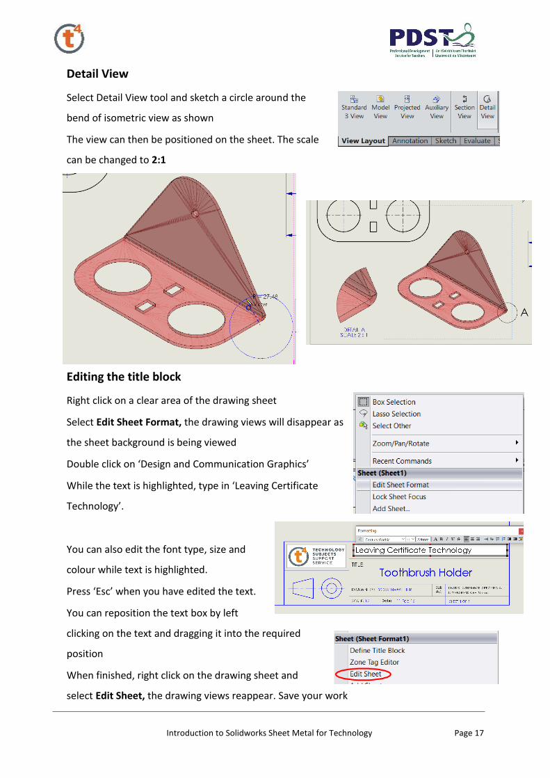
Detail View
Select Detail View tool and sketch a circle around the
bend of isometric view as shown
The view can then be positioned on the sheet. The scale
can be changed to 2:1
Editing the title block
Right click on a clear area of the drawing sheet
Select Edit Sheet Format, the drawing views will disappear as
the sheet background is being viewed
Double click on ‘Design and Communication Graphics’
While the text is highlighted, type in ‘Leaving Certificate
Technology’.
You can also edit the font type, size and
colour while text is highlighted.
Press ‘Esc’ when you have edited the text.
You can reposition the text box by left
clicking on the text and dragging it into the required
position
When finished, right click on the drawing sheet and
select Edit Sheet, the drawing views reappear. Save your work

Introduction to Solidworks Sheet Metal for Technology Page 18
The exercise is now complete

Introduction to Solidworks Sheet Metal for Technology Page 19
Exercise 2: Phone Holder
Introduction
This lesson focuses on designing a sheet metal part from the flattened state.to include a
series of bends. The model and drawings will also serve as a classroom for examination
questions based on developments and orthographic projection.
Learning Intentions
At the end of these exercises, you should be able to:
Create a sheet metal part, using Base Flange, Extruded Cut, Sketched Bend and Edit
Material commands
Create a drawing worksheet of the exercise
Prerequisite Knowledge
Introduction to sheet metal commands including a basic knowledge of SolidWorks from the
previous exercises (toothbrush holder and childs toy)
Saving Your Work
Save the file as Phone Holder to a folder called Phone Holder Exercise.
(Continue to save periodically throughout the exercise)

Introduction to Solidworks Sheet Metal for Technology Page 20
Creating the Sheet Metal Part
Creating the Sketch
Create a new Part.
Draw the following sketch on the Top Plane
Mirror the sketch. .
Dimension the sketch as shown

Introduction to Solidworks Sheet Metal for Technology Page 21
Add a R.25mm circle at end and trim excess
lines. Add a vertical relation to the circle centre
and an endpoint of the trimmed line.
Save your work.
The sketch should be fully defined.
Create the sheet metal feature
Select the Sheet Metal tab and select Base Flange .
The material thickness is 3mm.
Create the Sketched bends
NOTE:
The bends will be created in a logical sequence that would occur in
“real-life”, if you had to make the holder. This will allow the file to be
used as a teaching tool to explain the bending sequence
Draw a new sketch on the surface as shown

Introduction to Solidworks Sheet Metal for Technology Page 22
Select the Sketched Bend
command .
Bend Parameters:
end to be the fixed face
85 degree bend
Material Outside bend
position
Click OK
Change name of bend feature to back bend
(press Fn + F2)
Create another sketch on the other end as
shown
Select the Sketched Bend command
. Bend Parameters:
Centre to be the fixed face
90 degree bend
Material Outside bend position

Introduction to Solidworks Sheet Metal for Technology Page 23
Click OK
Change name of bend feature to Front bend 1
Draw another sketch
close to previous.
Dimension from the
bend surface not the
curvature edge
Repeat the
sketched bend
exercise to form
the J shape on
front of phone
holder using the
same parameters
Click OK .
Change name of bend feature to Front bend 2

Introduction to Solidworks Sheet Metal for Technology Page 24
Draw a final sketch for the two top bends
Select the Sketched Bend command .
Bend Parameters:
Rear surface to be the fixed face
85 degree bend
Bend centreline bend position
You may need to change direction of bend by selecting the
arrow on the screen
Click OK .
Rename bend feature to Top Bends
Save your work

Introduction to Solidworks Sheet Metal for Technology Page 25
Edit the material to Acrylic (Medium-high impact). Edit the appearance to a blue colour.
(see previous exercise for further information)
Your Phone Holder is now complete
You can use the Flatten feature to show in the flattened state

Introduction to Solidworks Sheet Metal for Technology Page 26
The Roll back command allow
you to show the sequence of
bends. Bring the cursor to the
design tree blue line, hold down
the left mouse button and move
over features to roll back the
development of the part.
Creating the Drawings & Worksheets
As in the previous exercise a drawing can be created of the
orthographic, isometric and developed views. Save your drawing in
the folder created earlier. The sheet template is DCG A4L
The sheet format
can be edited as in
the earlier exercise

Introduction to Solidworks Sheet Metal for Technology Page 27
Creating Worksheets
The question (JC Technology 2012 HL Part B) can be inserted as an
image into a sheet, once it has been saved as a picture (use print
screen or snip it tool)
To create a worksheet for Part (i),
drag and drop the flattened view of the part into the space. The
text can be hidden by right clicking and select Hide.

Introduction to Solidworks Sheet Metal for Technology Page 28
Use the Break
tool to
remove the
middle of the
view, increase
the gap to
110mm
Add text to
sheet

Introduction to Solidworks Sheet Metal for Technology Page 29
Add another sheet for Part (ii)
Save a number of roll back views
using the windows Snipping Tool
Insert them into the drawing
sheet.
Add some text to complete the
worksheet. Add a sketch line to
divide the sheet
Further sheets can be added to complete the other parts of the question
The exercise is now complete.
Save your work